EP1096104A1 - Apparatus and methods of testing and drilling a well - Google Patents
Apparatus and methods of testing and drilling a well Download PDFInfo
- Publication number
- EP1096104A1 EP1096104A1 EP00309388A EP00309388A EP1096104A1 EP 1096104 A1 EP1096104 A1 EP 1096104A1 EP 00309388 A EP00309388 A EP 00309388A EP 00309388 A EP00309388 A EP 00309388A EP 1096104 A1 EP1096104 A1 EP 1096104A1
- Authority
- EP
- European Patent Office
- Prior art keywords
- packer
- well
- drill
- wellbore
- string
- Prior art date
- Legal status (The legal status is an assumption and is not a legal conclusion. Google has not performed a legal analysis and makes no representation as to the accuracy of the status listed.)
- Granted
Links
- 238000012360 testing method Methods 0.000 title claims abstract description 65
- 238000005553 drilling Methods 0.000 title claims abstract description 51
- 238000000034 method Methods 0.000 title claims description 26
- 239000012530 fluid Substances 0.000 claims abstract description 57
- 238000004891 communication Methods 0.000 claims abstract description 18
- 238000007789 sealing Methods 0.000 claims abstract description 17
- 230000006835 compression Effects 0.000 claims description 13
- 238000007906 compression Methods 0.000 claims description 13
- 238000010998 test method Methods 0.000 claims description 8
- 239000000523 sample Substances 0.000 description 37
- 238000002955 isolation Methods 0.000 description 17
- 230000015572 biosynthetic process Effects 0.000 description 16
- 239000003381 stabilizer Substances 0.000 description 7
- 238000005086 pumping Methods 0.000 description 6
- 238000004519 manufacturing process Methods 0.000 description 3
- 238000013459 approach Methods 0.000 description 1
- 239000004568 cement Substances 0.000 description 1
- 238000010276 construction Methods 0.000 description 1
- 238000005520 cutting process Methods 0.000 description 1
- 238000011156 evaluation Methods 0.000 description 1
- 230000003993 interaction Effects 0.000 description 1
- 239000007788 liquid Substances 0.000 description 1
- 230000007774 longterm Effects 0.000 description 1
- 230000002265 prevention Effects 0.000 description 1
- 238000011084 recovery Methods 0.000 description 1
- 239000007787 solid Substances 0.000 description 1
- 238000012956 testing procedure Methods 0.000 description 1
Images


Classifications
-
- E—FIXED CONSTRUCTIONS
- E21—EARTH DRILLING; MINING
- E21B—EARTH DRILLING, e.g. DEEP DRILLING; OBTAINING OIL, GAS, WATER, SOLUBLE OR MELTABLE MATERIALS OR A SLURRY OF MINERALS FROM WELLS
- E21B49/00—Testing the nature of borehole walls; Formation testing; Methods or apparatus for obtaining samples of soil or well fluids, specially adapted to earth drilling or wells
- E21B49/08—Obtaining fluid samples or testing fluids, in boreholes or wells
- E21B49/087—Well testing, e.g. testing for reservoir productivity or formation parameters
-
- E—FIXED CONSTRUCTIONS
- E21—EARTH DRILLING; MINING
- E21B—EARTH DRILLING, e.g. DEEP DRILLING; OBTAINING OIL, GAS, WATER, SOLUBLE OR MELTABLE MATERIALS OR A SLURRY OF MINERALS FROM WELLS
- E21B33/00—Sealing or packing boreholes or wells
- E21B33/10—Sealing or packing boreholes or wells in the borehole
- E21B33/12—Packers; Plugs
- E21B33/128—Packers; Plugs with a member expanded radially by axial pressure
-
- E—FIXED CONSTRUCTIONS
- E21—EARTH DRILLING; MINING
- E21B—EARTH DRILLING, e.g. DEEP DRILLING; OBTAINING OIL, GAS, WATER, SOLUBLE OR MELTABLE MATERIALS OR A SLURRY OF MINERALS FROM WELLS
- E21B49/00—Testing the nature of borehole walls; Formation testing; Methods or apparatus for obtaining samples of soil or well fluids, specially adapted to earth drilling or wells
- E21B49/08—Obtaining fluid samples or testing fluids, in boreholes or wells
- E21B49/084—Obtaining fluid samples or testing fluids, in boreholes or wells with means for conveying samples through pipe to surface
Abstract
Description
- The present invention relates generally to apparatus and methods for servicing a well, and more particularly, to apparatus and methods for the early evaluation of a well after the borehole has been partially drilled and before casing has been cemented in the borehole such that testing of the well and further drilling may be carried out on a single trip of the tool into the well. The invention relates to apparatus and method for testing and drilling a well, and relates in particular to a test, drill and pull system and method of testing and drilling a well.
- During the drilling and completion of oil and gas wells, it is often necessary to test or evaluate the production capabilities of the well. This is typically done by isolating a subsurface formation or a portion of a zone of interest which is to be tested and subsequently flowing a sample of well fluid either into a sample chamber or up through a tubing string to the surface. Various data, such as pressure and temperature of the produced well fluids, may be monitored downhole to evaluate the long-term production characteristics of the formation.
- One commonly used well testing procedure is to first cement a casing in the wellbore and then to perforate the casing adjacent the formation or zone of interest. Subsequently, the well is flow-tested through the perforations. Such flow tests are commonly carried out with a drill stem test string located within the casing. The drill stem test string carries packers, tester valves, circulating valves and the like to control the flow of fluids through the drill stem test string.
- Although drill stem testing of cased wells provides very good test data, it has the disadvantage that the well must first be cased before the test can be conducted. Also, better reservoir data can often be obtained immediately after the well is drilled and before the formation has been severely damaged by drilling fluids and the like.
- For these reasons, it is often desired to evaluate the potential production capability of a well without incurring the cost and delay of casing the well. This has led to a number of attempts at developing a successful open-hole test which can be conducted in an uncased borehole.
- One approach which as been used for open-hole testing is the use of a weight-set, open-hole compression packer on a drill stem test string. To operate a weight-set, open-hole compression packer, a solid surface must be provided against which the weight can be set. Historically, this is accomplished by a perforated anchor which sets down on the bottom. Prior to such drill stem testing, it is necessary to remove the drill string from the well and then run the test string into the well. Afterwards, if it is desired to further drill the well, the test string must be removed so that the drill string may be run back into the well for the additional drilling procedure.
- Thus, there is a need for reducing the number of trips in and out of the well which reduces both the cost of testing and drilling and also allows the testing to be conducted at an early stage before significant damage is done to the formation or zone of interest. The present invention meets these needs by providing a testing system which allows an open-hole test to be carried out and then additional drilling to be done on the same trip into the well.
- The present invention includes a well testing system and method of testing and drilling a well. Specifically, the apparatus is referred to as a test, drill and pull tool. This apparatus is adapted for use on a tool or drill string for testing in an uncased wellbore.
- The apparatus comprises a packer having a set position for sealing engagement with the wellbore and packer and an unset position for disengagement from the wellbore, a tester valve in communication with the drill string and having an open position such that fluid from the well will flow into the drill string during a well test when the packer is set and further having a closed position, and a drill bit adapted for further drilling of the well after the packer lockout has been engaged. The packer is preferably a compression or squeeze packer which is set by setting down weight on the drill string and unset by picking up the drill string, the packer being resettable in this way without removal from the wellbore.
- The apparatus may also comprise a packer lockout having an engaged position which prevents resetting of the packer when weight is set down on the drill string and packer after the packer has been set and subsequently unset. The packer lockout is preferably engaged by rotation of the drill string. When this packer lockout is engaged, the drill bit may be rotated. In one embodiment, the drill bit may be rotated by rotating the drill string, and in another embodiment, the drill bit may be rotated by a mud motor actuated by pumping mud down the drill pipe.
- The tester valve may be a surface readout tester valve, and the apparatus may further comprise a valve probe latchably engagable with the tester valve. In the illustrated embodiment, the valve probe is connectable to a wireline on which the valve probe may be run into the wellbore and engaged with the tester valve. Pulling on the wireline will open the tester valve for the test, and slacking off on the wireline will close the tester valve. The valve probe may further comprise a sampler adapted for trapping a fluid sample during the well test and/or a flow meter or "spinner" for determining fluid flow rates therethrough during the well test.
- The setting and unsetting of the packer and the testing of the well with a tester valve may be carried out any number of times as desired prior to actuation of the packer lockout.
- The apparatus may also comprise an isolation valve in communication with the drill string and having a closed position for testing the well and an open position wherein the drill string is placed in communication with the well during a drilling operation. The isolation valve may be actuated by rotation of the drill string, or alternatively, the isolation valve may be configured such that it is pressure actuated.
- The apparatus additionally comprises a perforated anchor between the packer and drill bit. The perforated anchor is in communication with the tester valve, and fluid may flow through the perforated anchor into the drill string during a well test. A check valve is provided in the anchor and adapted for allowing fluid to enter the drill string during the well test and preventing discharge of fluid from the anchor during a drilling operation with the drill bit.
- Stated in another way, the apparatus of the present invention is adapted for use on a drill string in an uncased wellbore and comprises a packer having a set position for sealing engagement with the wellbore and an unset position disengaged from the wellbore, a tester valve in communication with the drill string and having an open position and a closed position, a valve probe connectable to the tester valve for actuating the tester valve between the open and closed positions thereof, and a drill bit adapted for further drilling of the wellbore. The packer is adapted such that, after a selected cycle of setting and unsetting of the packer, it cannot be reset, and the drill bit is adapted for further drilling after the selected cycle of setting and unsetting the packer. The prevention of resetting of the packer is preferably accomplished by a packer lockout which prevents resetting of the packer after the selected cycle of setting and unsetting the packer.
- The invention also includes a method of testing and drilling a well which comprises the step of running a tool string into the well and positioning the tool string adjacent to a bottom portion of the well. This tool string comprises a length of drill pipe, a packer connected to the drill pipe, a tester valve, and a drill bit. The method further comprises the steps of setting the packer into sealing engagement with an uncased borehole of the well, opening the tester valve so that the fluid will flow from a formation or zone of interest into the tool string, closing the tester valve, locking the packer such that it cannot be reset, unsetting the packer, drilling the well deeper with the drill bit.
- The step of opening the tester valve may comprise flowing fluid into the drill pipe and flowing at least a sample portion of the fluid through the drill pipe to the surface of the well.
- After the step of closing the tester valve, and before the step of locking the packer, the method may further comprise repeating the steps of opening the tester valve and closing the tester valve as many times as desired. After the step of closing the tester valve, and before the step of locking the packer, the method may also comprise unsetting the packer and repeating the steps of setting the packer, opening the tester valve and closing the tester valve as many times as desired. The method may further comprise running the tool string out of the well, unlocking the packer, and repeating the previously mentioned steps.
- The step of locking the packer may comprise actuating a packer lockout in the tool string, and in the preferred embodiment, this step is carried out by rotating the tool string.
- The method of testing and drilling a well may further comprise the steps of running a valve probe into the drill string on a wireline, and latching the valve probe to the tester valve. The step of opening the tester valve comprises applying tension to the wireline, and the step of closing the tester valve comprises slacking off on the wireline.
- During the step of drilling, fluid is pumped down the tool string while preventing flow of fluid from the well into the tool string. Drilling may be accomplished by rotating the tool string or pumping the fluid through a mud motor connected to the drill bit.
- Additionally, the method may comprise trapping a fluid sample while fluid is flowing from the formation or zone of interest and/or measuring a flow rate of the fluid flowing from the formation or zone of interest.
- In another aspect, the invention provides an apparatus for use on a drill string for testing an uncased wellbore comprising: a packer having a set position for sealing engagement with the wellbore and an unset position for disengagement from the wellbore; a tester valve in communication with the drill string and having an open position such that fluid from the well will flow into the drill string during a well test when the packer is set and further having a closed position; and a drill bit adapted for further drilling of the well after the packer has been set and unset.
- In an embodiment, the apparatus further comprises a packer lockout having an engaged position which prevents resetting of the packer after the packer has been set and unset; the drill bit may be rotated after the packer lockout has been engaged.
- In an embodiment, the apparatus further comprises a packer lockout having an engaged position which prevents resetting of the packer when weight is set down on the drill string and packer after the packer has been set and subsequently unset.
- In an embodiment, the packer may be set and unset as desired prior to engagement of the packer lockout.
- In an embodiment, the packer lockout is engaged by rotation of the drill string.
- In an embodiment, the packer is placed in the set position thereof when weight is set down on the drill string; and the packer is placed in the unset position thereof when weight is picked up on the drill string.
- In an embodiment, the tester valve is a surface readout tester valve.
- In an embodiment, the apparatus further comprises a valve probe latchably engageable with the tester valve. The valve probe may be connectable to a wireline on which the valve probe may be run into the wellbore and engaged with the tester valve, whereby pulling on the wireline will open the tester valve for the valve test and slacking off on the wireline will close the tester valve. The valve probe may comprise a sampler adapted for trapping a fluid sample during the well test. The valve probe may comprise a flow meter for determining fluid flow rates therethrough during the well test.
- In an embodiment, the packer is resettable without removal from the wellbore.
- In an embodiment, the apparatus further comprises an isolation valve in communication with the drill string and having a closed position for testing the well and an open position wherein the drill string is placed in communication with the well during drilling. The isolation valve may be actuated by rotation of the drill string. The isolation valve may be pressure actuated.
- In an embodiment, the further comprises a perforated anchor in communication with the tester valve through which the fluid may flow into the drill string during a well test. The may further comprise a check valve in the anchor adapted for allowing fluid to enter the drill string during the well test and preventing discharge of fluid from the anchor during drilling with the drill bit.
- In another aspect, the invention provides an apparatus for use in a drill string in an uncased wellbore comprising: a packer having a set position for sealing engagement with the wellbore and an unset position disengaged from the wellbore; a tester valve in communication with the drill string and having an open position and a closed position; and a drill bit adapted for drilling of the wellbore.
- In an embodiment, the packer is a compression packer which is placed in the set position when weight is set down on the drill string and is placed in the unset position when weight is picked up on the drill string.
- In an embodiment, the apparatus further comprises a packer lockout which may be actuated to prevent resetting of the packer after a selected cycle of setting and unsetting the packer.
- In an embodiment, the packer lockout is engaged by rotation of the drill string.
- In an embodiment, the tester valve is a surface readout tester valve.
- In an embodiment, the apparatus further comprises a valve probe connectable to the tester valve for actuating the tester valve between the open and closed positions thereof. The probe may be connectable to a wireline and adapted for latching onto the tester valve such that pulling on the wireline will open the tester valve and allow fluid to flow from the well into the drill string when the packer is in the set position and slacking off on the wireline will close the tester valve. The valve probe may comprise a sampler adapted for trapping a fluid sample during the well test. The valve probe may comprise a flow meter for determining fluid flow rates therethrough during the well test.
- In an embodiment, the apparatus further comprises an isolation valve having an open position wherein the drill bit is in communication with the well and a closed position for testing the well. The isolation valve may be actuated by rotation of the drill string. The isolation valve may be pressure actuated.
- In an embodiment, the apparatus further comprises a perforated anchor in communication with the tester valve through which the fluid may flow into the drill string during a well test.
- In an embodiment, the apparatus further comprises a check valve in the anchor adapted for allowing fluid to enter the drill string during the test and preventing discharge of fluid from the anchor during drilling with the drill bit.
- In an embodiment, rotation of the drill bit is carried out by rotation of the drill string.
- The packer is preferably resettable.
- In another aspect, the invention provides, apparatus for use in a drill string in an uncased wellbore comprising: a packer having a set position for sealing engagement with the wellbore and an unset position disengaged from the wellbore; a packer lockout which may be actuated to prevent resetting of the packer after a selected cycle of said setting and unsetting the packer; a tester valve in communication with the drill string and having an open position and a closed position; and a drill bit adapted for drilling of the wellbore after setting and unsetting the packer.
- In an embodiment, the packer lockout is engaged by rotation of the drill string.
- In an embodiment, the packer is a compression packer which is placed in the set position when weight is set down on the drill string and is placed in the unset position when weight is picked up on the drill string.
- In an embodiment, the drill bit may be rotated for further drilling of the wellbore after the packer lockout has been engaged.
- In another aspect, the invention provides a method of testing and drilling a well comprising the steps of:
- (a) running a tool string into the well and positioning the tool string adjacent to a bottom portion of the well, the tool string comprising a length of drill pipe, a packer connected to the drill pipe, a tester valve, and a drill bit;
- (b) setting the packer into sealing engagement with an uncased borehole of the well;
- (c) opening the tester valve so that fluid will flow from a zone of interest in the well into the tool string;
- (d) closing the tester valve;
- (e) unsetting the packer; and
- (f) drilling the well deeper with the drill bit.
-
- In an embodiment, step (c) comprises flowing fluid into the drill pipe and flowing at least a sample portion of the fluid through the drill pipe to the surface of the well.
- In an embodiment, the method further comprises:
- (g) running the tool string out of the well;
- (h) unlocking the packer; and
- (i) repeating steps (a) through (f).
-
- In an embodiment, the method further comprises: running a valve probe into the drill string on a wireline; and latching the valve probe into the tester valve; wherein: step (c) comprises applying tension to the wireline; and step (d) comprises slacking off on the wireline.
- In an embodiment, the method further comprises:
(g) during step (f)-pumping fluid down the tool string while preventing flow of fluid from the well into the tool string. - In an embodiment, the method further comprises trapping a fluid sample while fluid is flowing from the zone of interest.
- In an embodiment, the method further comprises measuring a flow rate of fluid flowing from the zone of interest.
- In an embodiment, the packer is a compression packer; the step of setting the packer comprises setting down weight on the tool string; and the step of unsetting the packer comprises picking up weight on the tool string.
- In an embodiment, step (f) comprises rotating the tool string.
- In an embodiment, the method further comprises, between steps (d) and (e), the step of locking the packer such that it cannot be reset.
- In an embodiment, the method further comprises, after step (d) and the stop of locking, repeating steps (c) and (d) as desired.
- In an embodiment, the method further comprising, after step (d) and before the step of locking, unsetting the packer and repeating steps (b), (c) and (d).
- In an embodiment, the step of locking comprises actuating a packer lockout in the tool string.
- In an embodiment, the step of actuating the packer comprises rotating the tool string.
- In another aspect, the invention provides a method of testing and drilling a well comprising the steps of:
- (a) running a tool string into the well and positioning the tool string adjacent to a bottom portion of the well, the tool string comprising a length of drill pipe, a packer connected to the drill pipe, a tester valve and a drill bit;
- (b) setting the packer into sealing engagement with an uncased borehole of the well;
- (c) locking the packer such that it cannot be reset;
- (d) unsetting the packer; and
- (e) drilling the well deeper with the drill bit.
-
- In an embodiment, step (c) comprises actuating a packer lockout in the tool string.
- In an embodiment, the step of actuating the packer lockout comprises rotating the tool string.
- In an embodiment, the method further comprises, after step (b) and before step (c), the steps of: opening the tester valve so that fluid will flow from a zone of interest in the well into the tool string; and closing the tester valve.
- In an embodiment, the steps of opening and closing the tester valve are repeatable prior to step (c).
- In an embodiment, the method further comprises, after step (b) and before step (c), unsetting the packer and repeating the step (b) and the steps of opening and closing the tester valve.
- Reference is now made to the accompanying drawings, in which:
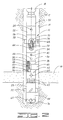
- FIG.1 illustrates an embodiment of a system according to the present invention as it is run into a well and positioned adjacent to the bottom thereof.
- FIG. 2 illustrates the drill stem testing system in a testing position within the well adjacent to a formation or zone of interest.
- FIG. 3 illustrates the drill stem testing system as used to further drill the well after testing has been conducted.
- Referring now the drawings, and more particularly to FIGS. 1 and 2, the test, drill and pull system or apparatus of the present invention is shown and generally designated by the numeral 10.
-
Apparatus 10 is used in servicing a well 12 having an uncasedborehole 14 intersecting a subsurface formation or zone ofinterest 16. As used herein, a reference to a method of servicing a well is used in a broad sense to include both the testing of a well wherein fluids are allowed to flow from the well and the treatment of a well wherein fluids are pumped into the well. "Servicing" also includes additional drilling. Also as used herein, a reference to a "zone of interest" includes a subsurface formation. -
Apparatus 10 is at the lower end of a length ofdrill pipe 18 which extends to the surface. A predetermined number ofdrill collars 20 are utilized to make up the drill string includingdrill pipe 18 andapparatus 10 to the desired length. - Below
drill collars 20 is abackup reversing valve 22 defining a reversingport 24 therein which may be placed in communication withdrill pipe 18 as will be further described herein. -
Apparatus 10 also includes a pair of spaceddrill collars stabilizer 30 and 32 thereon, respectively.Stabilizers 30 and 32guide apparatus 10 as it is lowered intoborehole 14 and keep the apparatus substantially centered within the borehole.Stabilizers 30 and 32 may be referred to as upper stabilizer 30 andlower stabilizer 32. - Disposed between upper and
lower stabilizers 30 and 32apparatus 10 comprises a surface readout (SRO) tester valve, and a reversingvalve 36, anopen hole packer 38. In the illustrated embodiment,packer 38 is shown as a compression packer having anelastomeric packer element 40 thereon. Other types of packers could also be used, and the invention is not intended to be limited to a compression packer.Apparatus 10 also comprises aperforated anchor 42 defining a plurality ofperforations 43 therein. - Below
lower stabilizer 32 is adrill bit 44.Drill bit 44 may be actuated by rotation ofdrill pipe 18 and thusapparatus 10. Alternatively,drill bit 44 may be actuated by pumping fluid through a mud motor (not shown) of a kind known in the art. - Reversing
valve 36 has anisolation valve 45 therein and also has at least one reversingport 46.Isolation 45 is a valve that isolates thedry drill pipe 18 from formation or zone ofinterest 16. Reversingports 46 are normally closed asapparatus 10 is run into well 12, as isisolation valve 45. In a preferred embodiment, reversingvalve 36 is rotation operated, andisolation valve 45 and reversingport 46 may be operated by a predetermined number of turns ofdrill pipe 18. In a specific embodiment, twenty turns are used to openisolation valve 45 and reversingport 46, but the invention is not intended to be so limited. More details of the operation of reversingvalve 36 will be discussed further. - Also, as will be further discussed herein, the compression packer embodiment of
packer 38 is placed in its sealing or set position by setting down weight ondrill pipe 18 such thatpacker element 40 is compressed or squeezed until it expands outwardly to engageborehole 14, as best seen in FIG. 2. For other types of packers, the packer is set in the normal manner, such as by inflating a packer element on an inflatable packer. -
Apparatus 10 also comprises apacker lockout 48 which has a disengaged position, as seen in FIGS. 1 and 2, in whichpacker 38 may be set into its sealing position.Packer lockout 40 also has an engaged position, as seen in FIG. 3, in whichpacker 38 is locked such that it cannot be reset when weight is again set down ondrill pipe 18. - In the illustrated embodiment,
packer lockout 48 includes acollar portion 50 ofpacker 38 which is threadingly connected to alockout sleeve 52 in threadedconnection 54. The lockout sleeve is attached to reversingvalve 36 such that rotation ofdrill pipe 18 will cause rotation oflockout sleeve 52 with respect tocollar portion 50. Ashoulder 56 is formed in the lower portion ofpacker 38, and alower end 58 oflockout sleeve 52 will engageshoulder 56 whenpacker lockout 48 is in its engaged position, as further described herein. -
Perforated anchor 42 has acheck valve 60 therein which allows fluid to flow intoperforations 44, when flowing fluid out of formation or zone ofinterest 16, but which prevents flow through the perforations when drilling. Drilling mud pumped down throughapparatus 10 is thus forced outjets 62 indrill bit 44 during drilling operations, as further described herein. -
SRO tester valve 34 has a latchingsurface 64 formed therein which is adapted for latching connection with a surface readouttester valve probe 68 which is run intoapparatus 10 on awireline 70. See FIG. 2.Tester valve probe 68 may have asampler 72 and/or a flow meter or "spinner" 74 therein. -
Apparatus 10 is attached to drillpipe 18 and configured as previously described.Drill pipe 18 andapparatus 10 are run to the bottom 76 ofborehole 14 of well 12 without fillingdrill pipe 18. That is,isolation valve 45 is closed, and the tool string is run withdrill pipe 18 dry or at least partially dry to achieve an underbalance for testing.Borehole 14 has previously been drilled to the depth of bottom 76 in a conventional manner. -
Packer 38 is set. For the illustrated compression packer, this is accomplished by setting down weight ondrill pipe 18 anddrill collars 20, thus expandingpacker element 40 into sealing engagement withborehole 14. Other types of packers other than compression packers may be set in their conventional manner, such as by pumping fluid into an inflatable packer element. The packer may be set and unset any number of times as desired prior to actuation of the packer lockout. - Surface readout
tester valve probe 68 is run intoapparatus 10 on awireline 70 and latched into latchingsurface 64 inSRO tester valve 34. Tension is applied towireline 70 which openstester valve 34 through the latched interaction oftester valve probe 68 which allows formation or zone ofinterest 16 to flow liquid into the previously "dry"drill pipe 18. That is, becausedrill pipe 18 is empty, or at least is at a lower pressure than the formation, whentester valve 34 is open, fluid is free to flow from formation or zone ofinterest 16 throughperforations 44 inperforated anchor 42 and upwardly throughapparatus 10. Testing may thus be carried out in a manner known in the art. By slacking off onwireline 70,tester valve 34 is closed for what is known as a "closed-in period." The steps of applying tension towireline 70 to opentester valve 34 and slacking off on the wireline to close the tester valve may be repeated as many times as desired. During the test, flowmeter 74 may be used to determine flow rates, andsampler 72 may be actuated to trap a fluid sample therein. - After testing has been completed,
tester valve probe 68 is unlatched from latchingsurface 64 intester valve 34 and removed from the tool by pulling onwireline 70.Tester valve probe 68 also may be configured such that fluid depths can be determined while pulling the probe out. -
Packer 38 may be unset, such as by picking up weight ondrill pipe 18. Other types of packers may be unset in a conventional manner, such as by deflating an inflatable packer element.Packer 38 may be set again andtester valve probe 68 latched again intotester valve 34 for another test. This cycle of settingpacker 38, testing, andunsetting packer 38 may be carried out as many times as desired. - When no more testing is desired,
drill pipe 18 is then rotated in a right-hand direction approximately twenty turns which opens reversingports 46 and also opensisolation valve 45 in rotation-operated reversingvalve 36. The fluid sample or "recovery" may then be reversed out of well 12 so that it can be analyzed. - After reversing out,
drill pipe 18 is rotated in a right-hand direction approximately an additional twenty turns. This causes reversingports 46 in rotation-operated reversingvalve 36 to be closed while keepingisolation valve 45 open. - These additional twenty turns of rotation also engage
packer lockout 48. That is, because of threadedconnection 54,packer lockout sleeve 52 is moved downwardly during the rotation such that it engagesshoulder 56 inpacker 38, as shown in FIG. 3.Packer lockout 48 is adapted such that once tension is placed again onpacker 38 to unseal it fromborehole 14, weight can then be set down again on the illustrated compression packer without recompressingpacker element 40 and resetting the packer. The engagement oflower end 58 oflockout sleeve 52 withshoulder 56 absorbs the weight so thatpacker element 40 is not recompressed. - Since
packer 38 is locked out and cannot be reset, weight may thus be placed ondrill bit 44 so that further drilling may be carried out. During the drilling operation, drilling mud is pumped down throughdrill pipe 18 andapparatus 10 to circulate out the cuttings. Drilling may be accomplished by rotatingdrill pipe 18 andapparatus 10, or alternatively, by pumping fluid through a mud motor (not shown) as previously mentioned. - Check
valve 60 inperforated anchor 42 closes off the perforations and directs the mud to be discharged outdrill bit 44 throughjets 62 as previously mentioned. FIG. 3 illustrates the locked-out position ofpacker 38 by means ofpacker lockout 48 and also illustrates additional drilling withdrill bit 44 to anew bottom 78 ofwell 12. - When the additional drilling is completed,
drill pipe 18 andapparatus 10 may be pulled out of well 12 to the surface. Rotation-operated reversingvalve 36 andpacker lockout 48 may then be reset to their original positions. After this,apparatus 10 may be run back into well 12 to test the newly drilled portion ofborehole 14 and for further drilling as desired. -
Backup reversing valve 22 has been described as being activated by rotation, but it could also be an internal pressure operated reversing valve.Backup reversing valve 22 in such a pressure-operated configuration could be set higher than the expected circulating pressures while drilling. If opened,drill pipe 18 would have to be pulled because the fluid could not be circulated down todrill bit 44. - It will be seen, therefore, that the test, drill and pull system and method of the present invention are well adapted to carry out the ends and advantages mentioned, as well as those inherent therein. While a presently preferred embodiment of the apparatus and method have been described for the purposes of this disclosure, numerous changes in the arrangement and construction of parts in the apparatus and steps in the method may be made by those skilled in the art. All such changes are encompassed within the scope and spirit of the appended claims.
Claims (10)
- An apparatus (10) for use on a drill string for testing an uncased wellbore (14) comprising: a packer (38) having a set position for sealing engagement with the wellbore and an unset position for disengagement from the wellbore; a tester valve (34) in communication with the drill string and having an open position such that fluid from the well will flow into the drill string during a well test when the packer is set and further having a closed position; and a drill bit (44) adapted for further drilling of the well after the packer has been set and unset.
- An apparatus according to claim 1, further comprising a packer lockout (48) having an engaged position which prevents resetting of the packer after the packer has been set and unset; and wherein the drill bit may be rotated after the packer lockout has been engaged.
- An apparatus (10) for use in a drill string in an uncased wellbore (14) comprising: a packer (38) having a set position for sealing engagement with the wellbore and an unset position disengaged from the wellbore; a tester valve (34) in communication with the drill string and having an open position and a closed position; and a drill bit (44) adapted for drilling of the wellbore.
- An apparatus according to claim 3, wherein the packer is a compression packer which is placed in the set position when weight is set down on the drill string and is placed in the unset position when weight is picked up on the drill string.
- An apparatus (10) for use in a drill string in an uncased wellbore comprising: a packer (38) having a set position for sealing engagement with the wellbore and an unset position disengaged from the wellbore; a packer lockout (48) which may be actuated to prevent resetting of the packer after a selected cycle of said setting and unsetting the packer; a tester valve (34) in communication with the drill string and having an open position and a closed position; and a drill bit (44) adapted for drilling of the wellbore after setting and unsetting the packer.
- An apparatus according to claim 5, wherein the packer lockout is engaged by rotation of the drill string.
- A method of testing and drilling a well comprising the steps of:(a) running a tool string into the well and positioning the tool string adjacent to a bottom portion of the well, the tool string comprising: a length of drill pipe (18); a packer (38) connected to the drill pipe; a tester valve (34); and a drill bit (44);(b) setting the packer into sealing engagement with an uncased borehole (14) of the well;(c) opening the tester valve so that fluid will flow from a zone of interest in the well into the tool string;(d) closing the tester valve;(e) unsetting the packer; and(f) drilling the well deeper with the drill bit.
- A method according to claim 7, wherein step (c) comprises flowing fluid into the drill pipe and flowing at least a sample portion of the fluid through the drill pipe to the surface of the well.
- A method of testing and drilling a well comprising the steps of:(a) running a tool string into the well and positioning the tool string adjacent to a bottom portion of the well, the tool string comprising: a length of drill pipe (18); a packer (38) connected to the drill pipe; a tester valve (34); and a drill bit (44);(b) setting the packer into sealing engagement with an uncased borehole (14) of the well;(c) locking the packer such that it cannot be reset;(d) unsetting the packer; and(e) drilling the well deeper with the drill bit.
- A method according to claim 9, wherein step (c) comprises actuating a packer lockout in the tool string.
Applications Claiming Priority (2)
| Application Number | Priority Date | Filing Date | Title |
|---|---|---|---|
| US427324 | 1982-09-29 | ||
| US09/427,324 US6343650B1 (en) | 1999-10-26 | 1999-10-26 | Test, drill and pull system and method of testing and drilling a well |
Publications (2)
| Publication Number | Publication Date |
|---|---|
| EP1096104A1 true EP1096104A1 (en) | 2001-05-02 |
| EP1096104B1 EP1096104B1 (en) | 2006-03-01 |
Family
ID=23694372
Family Applications (1)
| Application Number | Title | Priority Date | Filing Date |
|---|---|---|---|
| EP00309388A Expired - Lifetime EP1096104B1 (en) | 1999-10-26 | 2000-10-25 | Apparatus and methods of testing and drilling a well |
Country Status (5)
| Country | Link |
|---|---|
| US (1) | US6343650B1 (en) |
| EP (1) | EP1096104B1 (en) |
| DE (1) | DE60026249T2 (en) |
| DK (1) | DK1096104T3 (en) |
| NO (1) | NO318155B1 (en) |
Cited By (5)
| Publication number | Priority date | Publication date | Assignee | Title |
|---|---|---|---|---|
| FR2885947A1 (en) * | 2005-05-19 | 2006-11-24 | Schlumberger Services Petrol | APPARATUS AND METHOD FOR OBTAINING WELL BOTTOM SAMPLES |
| GB2431179A (en) * | 2005-09-15 | 2007-04-18 | Enventure Global Technology | Apparatus for radially expanding and plastically deforming a tubular member |
| WO2008015632A2 (en) * | 2006-08-02 | 2008-02-07 | Schlumberger Canada Limited | Technique and apparatus for drilling and completing a well in one half trip |
| US8479810B2 (en) | 2007-06-26 | 2013-07-09 | Paul David Metcalfe | Downhole apparatus |
| US9353606B2 (en) | 2010-11-16 | 2016-05-31 | Darcy Technologies Limited | Downhole method and apparatus |
Families Citing this family (19)
| Publication number | Priority date | Publication date | Assignee | Title |
|---|---|---|---|---|
| US6758273B2 (en) * | 2000-06-16 | 2004-07-06 | Richard B. Learned | Low-flow groundwater sampling system |
| US6530428B1 (en) * | 2000-10-26 | 2003-03-11 | Halliburton Energy Services, Inc. | Method and apparatus for in-situ production well testing |
| US6662644B1 (en) * | 2002-06-28 | 2003-12-16 | Edm Systems Usa | Formation fluid sampling and hydraulic testing tool |
| US7062959B2 (en) * | 2002-08-15 | 2006-06-20 | Schlumberger Technology Corporation | Method and apparatus for determining downhole pressures during a drilling operation |
| US6832515B2 (en) | 2002-09-09 | 2004-12-21 | Schlumberger Technology Corporation | Method for measuring formation properties with a time-limited formation test |
| US7331223B2 (en) * | 2003-01-27 | 2008-02-19 | Schlumberger Technology Corporation | Method and apparatus for fast pore pressure measurement during drilling operations |
| US6986282B2 (en) * | 2003-02-18 | 2006-01-17 | Schlumberger Technology Corporation | Method and apparatus for determining downhole pressures during a drilling operation |
| US7178392B2 (en) * | 2003-08-20 | 2007-02-20 | Schlumberger Technology Corporation | Determining the pressure of formation fluid in earth formations surrounding a borehole |
| US7124819B2 (en) * | 2003-12-01 | 2006-10-24 | Schlumberger Technology Corporation | Downhole fluid pumping apparatus and method |
| US7296637B2 (en) * | 2004-04-06 | 2007-11-20 | Ed Gudac | Oil drilling tool |
| US7407009B2 (en) * | 2004-12-16 | 2008-08-05 | Halliburton Energy Services, Inc. | Methods of using cement compositions comprising phosphate compounds in subterranean formations |
| WO2007009247A1 (en) * | 2005-07-19 | 2007-01-25 | Tesco Corporation | A method for drilling and cementing a well |
| CA2527265A1 (en) * | 2005-11-18 | 2007-05-18 | Smith, Winston Alan | A mud depression tool and process for drilling |
| US8136395B2 (en) | 2007-12-31 | 2012-03-20 | Schlumberger Technology Corporation | Systems and methods for well data analysis |
| US9109426B2 (en) | 2010-07-01 | 2015-08-18 | Basimah Khulusi | Apparatus and method for plugging blowouts |
| US20120000656A1 (en) * | 2010-07-01 | 2012-01-05 | Basimah Khulusi | Apparatus And Methods For Producing Oil and Plugging Blowouts |
| US9109427B2 (en) | 2010-07-01 | 2015-08-18 | Basimah Khulusi | Apparatus and method for plugging blowouts |
| WO2013079926A2 (en) * | 2011-11-28 | 2013-06-06 | Churchill Drilling Tools Limited | Drill string check valve |
| GB2550862B (en) * | 2016-05-26 | 2020-02-05 | Metrol Tech Ltd | Method to manipulate a well |
Citations (8)
| Publication number | Priority date | Publication date | Assignee | Title |
|---|---|---|---|---|
| US2280785A (en) * | 1938-10-04 | 1942-04-28 | Boynton Alexander | Well testing tool |
| US2831542A (en) * | 1953-01-19 | 1958-04-22 | Lynes Inc | Locking assembly for treating and testing tools |
| US3107729A (en) * | 1960-05-09 | 1963-10-22 | Jersey Prod Res Co | Apparatus for drill stem testing |
| US3578078A (en) * | 1970-01-12 | 1971-05-11 | Gen Oil Tools Inc | Earth borehole tool |
| EP0697501A2 (en) * | 1994-08-15 | 1996-02-21 | Halliburton Company | Integrated well drilling and formation evaluation system |
| EP0856636A2 (en) * | 1997-02-03 | 1998-08-05 | Halliburton Energy Services, Inc. | Method and apparatus for testing and sampling open-hole oil and gas wells |
| US5799733A (en) * | 1995-12-26 | 1998-09-01 | Halliburton Energy Services, Inc. | Early evaluation system with pump and method of servicing a well |
| WO1999045236A1 (en) * | 1998-03-06 | 1999-09-10 | Baker Hughes Incorporated | Formation testing apparatus and method |
Family Cites Families (3)
| Publication number | Priority date | Publication date | Assignee | Title |
|---|---|---|---|---|
| US5842528A (en) * | 1994-11-22 | 1998-12-01 | Johnson; Michael H. | Method of drilling and completing wells |
| US5697449A (en) * | 1995-11-22 | 1997-12-16 | Baker Hughes Incorporated | Apparatus and method for temporary subsurface well sealing and equipment anchoring |
| US6148912A (en) * | 1997-03-25 | 2000-11-21 | Dresser Industries, Inc. | Subsurface measurement apparatus, system, and process for improved well drilling control and production |
-
1999
- 1999-10-26 US US09/427,324 patent/US6343650B1/en not_active Expired - Lifetime
-
2000
- 2000-10-25 EP EP00309388A patent/EP1096104B1/en not_active Expired - Lifetime
- 2000-10-25 NO NO20005371A patent/NO318155B1/en unknown
- 2000-10-25 DE DE60026249T patent/DE60026249T2/en not_active Expired - Fee Related
- 2000-10-25 DK DK00309388T patent/DK1096104T3/en active
Patent Citations (8)
| Publication number | Priority date | Publication date | Assignee | Title |
|---|---|---|---|---|
| US2280785A (en) * | 1938-10-04 | 1942-04-28 | Boynton Alexander | Well testing tool |
| US2831542A (en) * | 1953-01-19 | 1958-04-22 | Lynes Inc | Locking assembly for treating and testing tools |
| US3107729A (en) * | 1960-05-09 | 1963-10-22 | Jersey Prod Res Co | Apparatus for drill stem testing |
| US3578078A (en) * | 1970-01-12 | 1971-05-11 | Gen Oil Tools Inc | Earth borehole tool |
| EP0697501A2 (en) * | 1994-08-15 | 1996-02-21 | Halliburton Company | Integrated well drilling and formation evaluation system |
| US5799733A (en) * | 1995-12-26 | 1998-09-01 | Halliburton Energy Services, Inc. | Early evaluation system with pump and method of servicing a well |
| EP0856636A2 (en) * | 1997-02-03 | 1998-08-05 | Halliburton Energy Services, Inc. | Method and apparatus for testing and sampling open-hole oil and gas wells |
| WO1999045236A1 (en) * | 1998-03-06 | 1999-09-10 | Baker Hughes Incorporated | Formation testing apparatus and method |
Cited By (8)
| Publication number | Priority date | Publication date | Assignee | Title |
|---|---|---|---|---|
| FR2885947A1 (en) * | 2005-05-19 | 2006-11-24 | Schlumberger Services Petrol | APPARATUS AND METHOD FOR OBTAINING WELL BOTTOM SAMPLES |
| GB2431179A (en) * | 2005-09-15 | 2007-04-18 | Enventure Global Technology | Apparatus for radially expanding and plastically deforming a tubular member |
| WO2008015632A2 (en) * | 2006-08-02 | 2008-02-07 | Schlumberger Canada Limited | Technique and apparatus for drilling and completing a well in one half trip |
| WO2008015632A3 (en) * | 2006-08-02 | 2008-04-03 | Schlumberger Ca Ltd | Technique and apparatus for drilling and completing a well in one half trip |
| US8479810B2 (en) | 2007-06-26 | 2013-07-09 | Paul David Metcalfe | Downhole apparatus |
| US8555985B2 (en) | 2007-06-26 | 2013-10-15 | Paul David Metcalfe | Permeability modification |
| US9353606B2 (en) | 2010-11-16 | 2016-05-31 | Darcy Technologies Limited | Downhole method and apparatus |
| US10337297B2 (en) | 2010-11-16 | 2019-07-02 | Halliburton Manufacturing And Services Limited | Downhole method and apparatus |
Also Published As
| Publication number | Publication date |
|---|---|
| EP1096104B1 (en) | 2006-03-01 |
| NO20005371D0 (en) | 2000-10-25 |
| DE60026249T2 (en) | 2006-08-24 |
| DK1096104T3 (en) | 2006-04-10 |
| US6343650B1 (en) | 2002-02-05 |
| DE60026249D1 (en) | 2006-04-27 |
| NO318155B1 (en) | 2005-02-07 |
| NO20005371L (en) | 2001-04-27 |
Similar Documents
| Publication | Publication Date | Title |
|---|---|---|
| EP1096104B1 (en) | Apparatus and methods of testing and drilling a well | |
| EP0781893B1 (en) | Apparatus and method for early evaluation and servicing of a well | |
| EP0856636B1 (en) | Method and apparatus for testing and sampling open-hole oil and gas wells | |
| US5287741A (en) | Methods of perforating and testing wells using coiled tubing | |
| US5687791A (en) | Method of well-testing by obtaining a non-flashing fluid sample | |
| EP0699819B1 (en) | Method and apparatus for well testing or servicing | |
| CA2155917C (en) | Early evaluation by fall-off testing | |
| US7624809B2 (en) | Method and apparatus for stimulating hydrocarbon wells | |
| US20080302529A1 (en) | Multi-zone formation fluid evaluation system and method for use of same | |
| US8807227B2 (en) | Method and apparatus for pressure testing a tubular body | |
| US10018039B2 (en) | Fast-setting retrievable slim-hole test packer and method of use | |
| US6491104B1 (en) | Open-hole test method and apparatus for subterranean wells | |
| US5887652A (en) | Method and apparatus for bottom-hole testing in open-hole wells | |
| US20170335667A1 (en) | Method for well completion | |
| AU745242B2 (en) | Early evaluation system with pump and method of servicing a well |
Legal Events
| Date | Code | Title | Description |
|---|---|---|---|
| PUAI | Public reference made under article 153(3) epc to a published international application that has entered the european phase |
Free format text: ORIGINAL CODE: 0009012 |
|
| AK | Designated contracting states |
Kind code of ref document: A1 Designated state(s): DE DK GB NL |
|
| AX | Request for extension of the european patent |
Free format text: AL;LT;LV;MK;RO;SI |
|
| 17P | Request for examination filed |
Effective date: 20010921 |
|
| AKX | Designation fees paid |
Free format text: DE DK GB NL |
|
| 17Q | First examination report despatched |
Effective date: 20031029 |
|
| GRAP | Despatch of communication of intention to grant a patent |
Free format text: ORIGINAL CODE: EPIDOSNIGR1 |
|
| GRAS | Grant fee paid |
Free format text: ORIGINAL CODE: EPIDOSNIGR3 |
|
| GRAA | (expected) grant |
Free format text: ORIGINAL CODE: 0009210 |
|
| AK | Designated contracting states |
Kind code of ref document: B1 Designated state(s): DE DK GB NL |
|
| REG | Reference to a national code |
Ref country code: GB Ref legal event code: FG4D |
|
| REG | Reference to a national code |
Ref country code: DK Ref legal event code: T3 |
|
| REF | Corresponds to: |
Ref document number: 60026249 Country of ref document: DE Date of ref document: 20060427 Kind code of ref document: P |
|
| PGFP | Annual fee paid to national office [announced via postgrant information from national office to epo] |
Ref country code: GB Payment date: 20060915 Year of fee payment: 7 |
|
| PGFP | Annual fee paid to national office [announced via postgrant information from national office to epo] |
Ref country code: DK Payment date: 20060919 Year of fee payment: 7 |
|
| PGFP | Annual fee paid to national office [announced via postgrant information from national office to epo] |
Ref country code: NL Payment date: 20060921 Year of fee payment: 7 |
|
| PGFP | Annual fee paid to national office [announced via postgrant information from national office to epo] |
Ref country code: DE Payment date: 20061031 Year of fee payment: 7 |
|
| PLBE | No opposition filed within time limit |
Free format text: ORIGINAL CODE: 0009261 |
|
| STAA | Information on the status of an ep patent application or granted ep patent |
Free format text: STATUS: NO OPPOSITION FILED WITHIN TIME LIMIT |
|
| 26N | No opposition filed |
Effective date: 20061204 |
|
| REG | Reference to a national code |
Ref country code: DK Ref legal event code: EBP |
|
| GBPC | Gb: european patent ceased through non-payment of renewal fee |
Effective date: 20071025 |
|
| NLV4 | Nl: lapsed or anulled due to non-payment of the annual fee |
Effective date: 20080501 |
|
| PG25 | Lapsed in a contracting state [announced via postgrant information from national office to epo] |
Ref country code: DE Free format text: LAPSE BECAUSE OF NON-PAYMENT OF DUE FEES Effective date: 20080501 |
|
| PG25 | Lapsed in a contracting state [announced via postgrant information from national office to epo] |
Ref country code: NL Free format text: LAPSE BECAUSE OF NON-PAYMENT OF DUE FEES Effective date: 20080501 Ref country code: DK Free format text: LAPSE BECAUSE OF NON-PAYMENT OF DUE FEES Effective date: 20071031 |
|
| PG25 | Lapsed in a contracting state [announced via postgrant information from national office to epo] |
Ref country code: GB Free format text: LAPSE BECAUSE OF NON-PAYMENT OF DUE FEES Effective date: 20071025 |