BACKGROUND OF THE INVENTION
FIELD OF THE INVENTION
The present invention relates to an impeller of a
circumferential current pump (so-called "wesco pump") used as
an in-tank type fuel pump of an automobile and a method of
forming the impeller.
DESCRIPTION OF THE PRIOR ART
An in-tank type circumferential current pump having an
improved property for being mounted to a vehicle and having a
low noise and a small pressure change has been conventionally
used in a fuel pump for an electronically controlled type
fuel injection apparatus of an automobile.
Figs. 23 to 25 show a circumferential current pump 51
for an automobile. The circumferential current pump 51 shown
in these drawings is placed within a fuel tank (not shown),
and is structured such as to apply an energy to a fuel by a
vane 54 formed on an outer periphery of an impeller 52 when
the impeller 52 is rotated by a motor 53 so as to increase a
pressure of the fuel flowing into a pump flow passage 56 from
a fuel inlet port 55 and discharge the fuel having the
increased pressure to an engine side from a fuel discharge
port 57.
In the circumferential current pump 51 mentioned above,
in order to maintain a pump efficiency and a discharge
pressure in a desired state, it is necessary to set gaps w1
and w2 in a side of side surfaces 58a and 58b of the impeller
52 within a predetermined size so as to reduce a leaked flow
amount. Further, in the circumferential current pump 51
mentioned above, since the impeller 52 is always in contact
with the fuel within the fuel tank, a phenol resin or a PPS
resin excellent in a solvent resistance is used as a material
for the impeller 52, whereby the impeller 52 is formed in a
desired shape in accordance with an injection molding.
However, when using the injection molded impeller 52 as
it is, the sizes of the gaps w1 and w2 on the side surfaces
58a and 58b of the impeller 52 do not satisfy a desirable
accuracy due to a surface accuracy of the side surfaces 58a
and 58b of the impeller 52, so that desired pump efficiency
and discharge pressure can not be obtained.
Accordingly, in the conventional circumferential
current pump 51, a width of the impeller 52 is finished at a
high accuracy by polishing both of the side surfaces 58a and
58b of the injection molded synthetic resin impeller 52 and a
surface accuracy of both of the side surfaces 58a and 58b of
the impeller 52 is finished at a high accuracy. Therefore,
the conventional impeller 52 has a disadvantage that a
process and labor for working is much and a producing cost is
increased (a first prior art).
Further, as shown in Fig. 26, there has been proposed
an impeller 52 structured such as to reduce a resistance
applied to both of the side surfaces 58a and 58b in
comparison with the first prior art in which a whole of both
of the side surfaces 58a and 58b forms a seal portion, by
forming an annular recess 60 on both of the side surfaces 58a
and 58b, forming a first seal portion S1 in an outer
peripheral side thereof and forming a second seal portion S2
in an inner peripheral side thereof (refer to Japanese
Unexamined Patent Publication No. 7-151091). However, since
the impeller 52 is structured such that two seal portions S1
and S2 are formed in such a manner as to be apart from each
other in a radial direction, it is necessary to polish both
of the side surfaces 58a and 58b after the injection molding,
in the same manner as that of the prior art mentioned above.
Accordingly, the impeller 52 shown in Fig. 26 also has a
disadvantage that a process and labor is much and a producing
cost is increased in the same manner as that of the prior art
mentioned above (a second prior art).
Accordingly, the applicant of the present invention
proposed an invention structured such that a recess portion
61 is formed in a center portion of both of the side surfaces
58a and 58b of the impeller 52, a gate 62 for injection is
arranged in the recess portion 61 and a pressure adjusting
hole 63 is formed as shown in Fig. 27, whereby the injection
molded impeller 52 can be used as it is without being
polished (Japanese Unexamined Patent Publication No. 9-158885
(a third prior art)). However, in correspondence to a high
performance of a fuel pump in recent years, it has been
desired to provide an impeller having a higher accuracy.
SUMMARY OF THE INVENTION
Accordingly, an object of the present invention is to
provide an impeller for a circumferential current pump which
can solve the disadvantages in the prior arts mentioned above,
and a method of forming the same.
In accordance with a first aspect of the present
invention, there is provided an impeller for a
circumferential current pump which is provided with a
plurality of vane grooves in an outer peripheral side of a
synthetic resin disc-like member rotated by a motor and is
rotatably received within a substantially disc-like space
formed between a pump casing and a pump cover, wherein a
recess portion having a predetermined radius around a center
of rotation is formed on at least one of one side surface
opposing to the pump casing of the disc-like member and
another side surface opposing to the pump cover. Further,
the structure is characterized in that a ratio (L/2t) between
the sum (t1 + t2 = 2t) of a gap (t1) between the one side
surface and the pump casing and a gap (t2) between the
another side surface and the pump cover, and a size (L = R0 -
H - R1) obtained by subtracting a radial groove length (H) of
the vane groove and a radial size (R1) of the recess portion
from a radial size (R0) of the disc-like member satisfies a
relation 66 ≦ (L/2t). In this case, the recess portion
includes a substantially disc-like recess portion around a
center of rotation of the disc-like member and a
substantially annular recess portion around a center of
rotation of the disc-like member.
In accordance with the present invention having the
structure mentioned above, since it is possible to make the
size (L) of the side surface functioning as a seal portion as
small as possible, it is possible to form the side surface
functioning as the seal portion at a high accuracy only in
accordance with an injection molding. Therefore, in
accordance with the present invention, a polishing of the
impeller side surface is not required, so that it is possible
to reduce a process and labor for producing the impeller.
Further, in accordance with the present invention, as
mentioned above, since it is possible to form the side
surface functioning as the seal portion of the impeller at a
high accuracy, it is possible to make the gap sizes (t1 and
t2) smaller than those of the third prior art.
In accordance with a second aspect of the present
invention, there is provided an impeller for a
circumferential current pump which is provided with a
plurality of vane grooves in an outer peripheral side of a
synthetic resin disc-like member rotated by a motor and is
rotatably received within a substantially disc-like space
formed between a pump casing and a pump cover. Then, the
impeller for the circumferential current pump is structured
such that a recess portion having a predetermined radius
around a center of rotation is formed on at least one of one
side surface opposing to the pump casing of the disc-like
member and another side surface opposing to the pump cover,
and a plurality of grooves extending in a radial direction
within the recess portion are formed in a radial shape.
In accordance with the present invention having the
structure mentioned above, a plurality of grooves are formed
in a radial shape so as to reduce a solid portion in the
recess portion, whereby a cooling efficiency at a time of
injection molding can be increased, a cycle time for the
injection molding can be reduced, and a deformation of a
whole of the impeller due to a molding shrinkage (sink mark).
Further, in accordance with the present invention, since a
plurality of grooves are formed in a radial shape as
mentioned above and the solid portions between the grooves
function as a rib, it is possible to reduce a weight without
reducing a rigidity of the impeller and it is possible to
reduce a used amount of the synthetic resin material.
In accordance with a third aspect of the present
invention, there is provided an impeller for a
circumferential current pump as recited in the second aspect
mentioned above, wherein a ratio (L/2t) between the sum (t1 +
t2 = 2t) of a gap (t1) between the one side surface and the
pump casing and a gap (t2) between the another side surface
and the pump cover, and a size (L = R0 - H - R1) obtained by
subtracting a radial groove length (H) of the vane groove and
a radial size (R1) of the recess portion from a radial size
(R0) of the disc-like member satisfies a relation 66 ≦
(L/2t).
In accordance with the present invention having the
structure mentioned above, it is possible to obtain the
effects of the first aspect and the second aspect in a
combined manner.
In accordance with a fourth aspect of the present
invention, there is provided an impeller for a
circumferential current pump as recited in any one of the
first to third aspects, wherein a shape between the vane
grooves on a side surface of the disc-like member is
substantially rectangular.
In accordance with the present invention having the
structure mentioned above, the impeller can be easily
released from the mold after the injection molding, whereby
it is possible to prevent an inferior mold release and
prevent the impeller from being deformed together with the
mold release.
In accordance with a fifth aspect of the present
invention, there is provided an impeller for a
circumferential current pump as recited in any one of the
first to third aspects, wherein a shape of the vane groove on
a side surface of the disc-like member is formed in such a
manner as to expand a groove width from an inner portion in a
radial direction toward an outer portion, and a shape between
the vane grooves is formed in a substantially trapezoidal
shape in which a width is reduced from the inner portion in
the radial direction toward the outer portion.
In accordance with the present invention having the
structure mentioned above, the impeller can be more easily
released from the mold after the injection molding than the
invention described in the fourth aspect, so that it is
possible to further effectively prevent the inferior mold
release and prevent the impeller from being deformed together
with the mold release.
In accordance with a sixth aspect of the present
invention, there is provided an impeller for a
circumferential current pump as recited in any one of the
first to fifth aspects, wherein a corner portion in a bottom
portion of the vane groove is beveled.
In accordance with the present invention having the
structure mentioned above, the impeller can be easily
released from the mold after the injection molding, whereby
it is possible to reduce a deformation of the impeller and an
inferior mold release at a time of releasing from the mold.
In accordance with a seventh aspect of the present
invention, there is provided an impeller for a
circumferential current pump as recited in any one of the
first to sixth aspects, wherein a pressure adjusting hole
extending through the another side surface from the one side
surface is formed at an inner position in a radial direction
from a position at which a ring gate for the injection
molding is arranged, within the recess portion.
In accordance with the present invention having the
structure mentioned above, an injected synthetic resin
material is smoothly supplied to a portion of the impeller in
which a surface accuracy is required. Further, a pin for
forming the pressure adjusting hole is arranged within a
metal mold for the injection molding, whereby a surface rough
portion together with a weld phenomenon is received within
the recess portion even when the weld phenomenon is generated,
so that the surface accuracy of the impeller side surface is
not deteriorated.
In accordance with an eighth aspect of the present
invention, there is provided a method of forming an impeller
for a circumferential current pump in which a plurality of
vane grooves are formed in an outer peripheral side of a
synthetic resin disc-like member and a recess portion having
a predetermined radius around a center of rotation is formed
on at least one of one side surface of the disc-like member
and another side surface thereof. Further, the structure is
characterized in that a ring gate for an injection molding is
arranged at a position corresponding to the recess portion
and a synthetic resin is injected into a cavity from the ring
gate.
In accordance with the present invention having the
structure mentioned above, a burr generated at a time of
cutting the ring gate is received within the recess portion
of the impeller, so that a surface accuracy of the impeller
side surface is not deteriorated and it is possible to
injection mold an impeller having a high accuracy.
BRIEF DESCRIPTION OF THE DRAWINGS
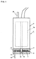
Fig. 1 is a front elevational view showing a part of a
circumferential current pump in accordance with a first
embodiment of the present invention in a broken manner;
Fig. 2 is a view showing a part of Fig. 1 in an
enlarged manner;
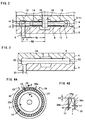
Fig. 3 is a cross sectional view showing a combined
state between a pump casing and a pump cover;
Figs. 4A and 4B are views for explaining an operating
state of the circumferential currant pump, in which Fig. 4A
is a schematic plan view for explaining the operating state
of the circumferential current pump and Fig. 4B is a cross
sectional view along a line A-A in Fig. 4A;
Fig. 5 is a side elevational view of an impeller;
Fig. 6 is a cross sectional view along a line B-B in
Fig. 5;
Figs. 7A and 7B are views showing a shape of a vane
groove as seen from a side surface side of the impeller, in
which Fig. 7A is a view of a shape of a first vane groove and
Fig. 7B is a view of a shape of a second vane groove;
Fig. 8 is a view of a shape of the vane grove as seen
from an outer peripheral surface side of the impeller;
Fig. 9 is a view showing a first modified example of
the shape of the vane groove as seen from a side surface side
of the impeller;
Fig. 10 is a view showing a second modified example of
the shape of the vane groove as seen from a side surface side
of the impeller;
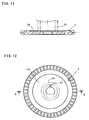
Fig. 11 is a cross sectional view showing a relation
between the impeller and a ring gate (a cross sectional view
along a line C-C in Fig. 12);
Fig. 12 is a plan view showing a relation between the
impeller and the ring gate;
Fig. 13 is a cross sectional view showing a first
example of an injection molding metal mold;
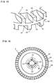
Fig. 14 is a cross sectional view showing a second
example of the injection molding metal mold;
Fig. 15 is a perspective view partly showing an outer
appearance of an outer peripheral end portion of the
impeller;
Fig. 16 is a side elevational view of the impeller
showing another method of forming a pressure adjusting hole;
Fig. 17 is a side elevational view of an impeller
showing a second embodiment in accordance with the present
invention;
Fig. 18 is a cross sectional view along a line D-D in
Fig. 17;
Fig. 19 is a graph showing a relation between a
dimensionless amount (L/2t) and a no-discharge pressure;
Fig. 20 is a graph showing a relation between the
dimensionless amount (L/2t) and a discharge flow amount;
Fig. 21 is a partly enlarged cross sectional view of a
circumferential current pump in accordance with a third
embodiment of the present invention;
Fig. 22 is a front elevational view of an impeller for
the circumferential current pump in accordance with the third
embodiment of the present invention;
Fig. 23 is a front elevational view showing a part of a
conventional circumferential current pump in a broken manner;
Fig. 24 is a view showing a part of Fig. 21 in an
enlarged manner;
Fig. 25 is a side elevational view of an impeller
showing a first conventional embodiment;
Fig. 26 is a side elevational view of an impeller
showing a second conventional embodiment; and
Fig. 27 is a side elevational view of an impeller
showing a third conventional embodiment.
DESCRIPTION OF THE PREFERRED EMBODIMENTS
A description will be in detail given below of
embodiments in accordance with the present invention with
reference to the accompanying drawings.
[First Embodiment]
Figs. 1 and 2 are views showing a circumferential
current pump 1 in accordance with a first embodiment of the
present invention. Among them, Fig. 1 is a front elevational
view showing a part of the circumferential current pump 1 in
a broken manner. Further, Fig. 2 is a cross sectional view
showing a part of Fig. 1 in an enlarged manner.
As shown in these drawings, the circumferential current
pump 1 in accordance with the present embodiment is
constituted by a pump portion 2 and a motor portion 3. Among
them, the pump portion 2 is provided with a pump casing 4
arranged in a lower end portion of the motor portion 3, a
pump cover 5 assembled in a lower surface side of the pump
casing 4, and a substantially disc-like impeller 7 rotatably
received within a substantially disc-like space 6 formed
between the pump casing 4 and the pump cover 5.
Since the impeller 7 is placed within a fuel tank (not
shown), a phenol resin or a PPS resin excellent in a solvent
resistance is used and the impeller 7 is formed in a desired
shape in accordance with an injection molding.
The impeller 7 is structured such that a plurality of
vane grooves 12 are formed in each of both side surfaces 10
and 11 in an outer peripheral end portion of a disc-like
member 8 and vanes 13 between the vane grooves 12 and 12 are
a half pitch shifted between one side surface 10 side and
another side surface 11 side, as in detail shown in Figs. 5,
6, 8 and 15. Further, a disc-like recess portion 14 having a
predetermined radius around a center of rotation of the
impeller 7 is formed in both side surfaces 10 and 11 of the
impeller 7. Further, an axial hole 15 is formed in a center
portion of the impeller 7, and a pressure adjusting hole 17
communicated with the recess portions 14 and 14 in both side
surfaces 10 and 11 of the impeller 7 is formed near the axial
hole 15. In this case, a rotation preventing portion 16 is
engaged with a notch portion (not shown) of a motor drive
shaft 18 so as to receive a drive force transmitted from the
motor portion 3. Further, the pressure adjusting hole 17 is
structured such as to balance a pressure applied to both side
surfaces 10 and 11 of the impeller 7 so as to enable the
impeller 7 to rotate in a state of being a little apart from
the pump casing 4 and the pump cover 5. Further, the vane
groove 12 of the impeller 7 is structured such that a shape
in a side surface side and a shape in an outer peripheral
side are formed in a substantially rectangular shape, and an
inner end portion in a radial direction is cut up so as to
form a substantially circular arc shape.
Figs. 19 and 20 are graphs showing a relation between a
radius of the recess portion 14 in the injection molded
impeller 7 and a pump performance, that is, a relation
between a size of a seal portion S and the pump performance
(refer to Fig. 2). In these drawings, a horizontal axis
corresponds to a dimensionless amount expressed by a rate
between a size (L) of the seal portion and a gap (2t) of the
impeller side surface. Further, a vertical axis in Fig. 19
corresponds to a no-discharge pressure and a vertical axis in
Fig. 20 corresponds to a discharge flow amount. In this case,
in Fig. 2, in the case of setting a gap between one side
surface 10 of the impeller 7 and the pump casing 4 to t1 and
setting a gap between another side surface 11 of the impeller
7 and the pump cover 5 to t2, the sum (2t) of the gaps in
both side surfaces 10 and 11 of the impeller 7 is expressed
by a formula (2t) = (t1) + (t2). Further, in the case of
setting a radius of the disc-like member 8 to R0, setting a
radius of the disc-like recess portion 14 to R1 and setting a
radial groove length of the vane groove 12 to H, the size (L)
of the seal portion S is expressed by a formula (L) = (R0) -
(H) - (R1). Further. P0 in Fig. 19 is a non-discharge
pressure required for a fuel pump and V0 in Fig. 20 is a
discharge flow amount required for the fuel pump.
That is, Fig. 19 shows a relation between the value
(L/2t) and the non-discharge pressure. A fuel can be
discharged to an engine side at a substantially constant non-discharge
pressure (P0) by setting the value so as to satisfy
a relation 66 ≦ (L/2t). Further, Fig. 20 shows a relation
between the value (L/2t) and the discharge flow amount. The
fuel can be discharged at a substantially constant discharge
flow amount (V0) by setting the value so as to satisfy the
relation 66 ≦ (L/2t) in the same manner as the relation
between the value (L/2t) and the non-discharge pressure.
Then, in accordance with the present embodiment, the sizes of
the respective portions in the impeller 7 are set so as to
satisfy a relation 66 = (L/2t). As a result, it is possible
to make the size L of the seal portion S smaller than the
third prior art and it is possible to make the surface
accuracy of the seal portion S higher than the third prior
art. Accordingly, it is possible to use the injection molded
impeller 7 as it is, and a polishing of both side surfaces 10
and 11 in the impeller 7 which is required in the first and
second prior arts is not required.
Figs. 11 to 13 show a method of forming the impeller 7.
That is, the structure is made such that a ring gate 21 for
injecting a synthetic resin within a cavity 20 for forming
the impeller is arranged in a portion corresponding to the
recess portion 14 of the impeller 7. In this case, Fig. 13
shows an example of an injection molding metal mold 22, the
injection molding metal mold 22 is a two-separated metal mold
comprising an upper die 23 and a lower die 24, and the cavity
20 for forming the impeller is formed on a joint surface
between the upper die 23 and the lower die 24. Further, the
ring gate 21 is formed in such a manner as to open to the
cavity 20 corresponding to the recess portion 14 of the
impeller 7 in the upper die 23. Further, Fig. 14 shows
another example of the injection molding metal mold 22. The
injection molding metal mold 22 is constituted by a first
upper die 25 for forming the recess portion of the impeller 7,
a second upper die 26 arranged in an outer peripheral side of
the first upper die 25, a first lower die 27 for forming the
recess portion 14 of the impeller 7 and a second lower die 28
arranged in an outer peripheral side of the first lower die
27, a separation surface 30 between the first upper die 25
and the second upper die 26 and a separation surface 31
between the first lower die 27 and the second lower die 28
are positioned in the recess portion 14, and the ring gate 21
is formed in the first upper die 25. As mentioned above, in
accordance with the present embodiment, the separation
surfaces 30 and 31 of the injection molding metal mold 22 are
positioned in the recess portion 14 and the ring gate 21 is
positioned in the recess portion 14, whereby a burr and a
surface rough portion generated on the separation surfaces 30
and 31 of the injection molding metal mold 22 and a released
surface of the ring gate 21 are received within the recess
portion 14, so that the surface accuracy of both side
surfaces 10 and 11 (the seal portion S) in the impeller 7 is
not deteriorated and a disadvantage that the gaps (t1 and t2)
in the side of both side surfaces 10 and 11 of the impeller 7
are increased is not generated.
Fig. 3 is a view showing a combined state between the
pump casing 4 and the pump cover 5. Further, Fig. 4 is a
schematic view showing a relation among a pump flow passage
32, a fuel inlet port 33, a fuel outlet port 34 and the
impeller 7. As shown in these drawings, the substantially
disc-like space 6 for rotatably receiving the impeller 7 is
formed on the joint surface between the pump casing 4 and the
pump cover 5. Further, the fuel inlet port 33 of the pump
cover 5 and the fuel output port 34 of the pump casing 4 are
communicated with the pump flow passage 32 formed in an outer
peripheral side of the disc-like space 6.
In accordance with the present embodiment having the
structure mentioned above, as shown in Figs. 1 and 4, when
the impeller 7 is rotated and driven by a motor 3a of the
motor portion 3, the fuel within the fuel tank (not shown)
flows into the pump flow passage 32 from the fuel inlet port
33. Then, the fuel flowing into the pump flow passage 32
from the fuel inlet port 33 receives an energy from the
rotating impeller 7 and a pressure of the fuel is increased
by the impeller 7 while moving to the fuel outlet port 34
along the substantially annular pump flow passage 32. Then,
the fuel having a sufficiently increased pressure passes
through a flow passage (not shown) of the motor portion 3
from the fuel outlet port 34 and is supplied to the engine
(not shown) from a fuel discharge port 35. In this case, as
shown in Fig. 4, a partition wall portion 36 is formed
between the fuel inlet port 33 and the fuel outlet port 34.
A gap t3 between a peripheral surface 36a of the partition
wall portion 36 and an outer peripheral surface 37 of the
impeller 7 is set to be smaller than a gap t4 between a
peripheral surface 32a of the pump flow passage 32 and the
outer peripheral surface 37 of the impeller 7. Further, a
gap between both side surfaces 36b and 36c of the partition
wall portion 36 and both side surfaces 10 and 11 of the
impeller 7 is set to a size equal to the gap size (t1 and t2)
of the seal portion S in the impeller 7. That is, the gap in
the side of the outer peripheral surface 37 of the impeller 7
and in the side of both side surfaces 10 and 11 is rapidly
narrowed by the partition wall portion 36, whereby the fuel
having the increased pressure is prevented from being leaked
out to the fuel inlet port 33 side from the fuel outlet port
34 side. Further, the fuel within the pump flow passage 32
is prevented by the seal portion S of the impeller 7 from
being leaked out inward in a radial direction.
As mentioned above, in accordance with the present
embodiment, since the seal portion S is formed in a limited
range in an inner peripheral side of the vane groove 12 at
only one portion and a width of the seal portion S is short,
the surface accuracy (a flatness, a total run-out tolerance
in an axial direction, a surface roughness and the like) of
the seal portion S is high even in the impeller 7 immediately
after being injection molded, and a polishing of the impeller
7 is not required. Therefore, in accordance with the present
embodiment, it is possible to reduce a process and labor for
working the impeller 7 in comparison with the first prior art
and the second prior art, so that it is possible to reduce a
producing cost.
Further, in accordance with the present embodiment, it
is possible to make the size L of the seal portion S in the
impeller 7 smaller than the third prior art and it is
possible to make the surface accuracy of the seal portion (on
a side surface) S in the impeller 7 than the third prior art.
Accordingly, the circumferential current pump 1 using the
impeller 7 in accordance with the present embodiment can
achieve a more excellent pump performance.
Further, in accordance with the present embodiment,
since all of the inner side in the radial direction from the
seal portion S in the impeller 7 corresponds to the recess
portion 14 and a thickness of the impeller 7 is reduced, it
is possible to accurately form the axial hole 15 with
reducing an influence of a molding shrinkage (sink mark).
Therefore, in accordance with the present embodiment, it can
be expected that a rotating accuracy of the impeller 7 is
improved and the pump performance is improved.
In this case, in the present embodiment, as shown in
Fig. 7, by beveling a corner portion in a bottom portion of
the vane groove 12 in the impeller in an R surface (refer to
Fig. 7A) and beveling in a C surface (refer to Fig. 7B), the
impeller 7 can be easily released from the mold after the
injection molding and a deformation of the impeller 7 at a
time of releasing from the mold and an inferior mold release
can be reduced.
Further, as shown in Fig. 9, by forming a shape in the
side of the side surface of the vane groove 12 in a
substantially trapezoidal shape and forming a shape in the
side of the side surface of the vane 13 between the vane
grooves 12 and 12 in a rectangular shape, the impeller 7
after the injection molding can be easily released from the
mold and it is possible to prevent the inferior mold release
and prevent the impeller 7 from being deformed together with
the mold release. A size of the root portion of the vane 13
is largely changed when the root portion of the vane 13 is
narrower than the front end portion in the outer peripheral
side of the vane 13 since the vane 13 of the impeller 7 after
the injection molding is structured such as to shrink toward
a root portion thereof. This is because of preventing the
disadvantage that the metal mold is held between the adjacent
vanes 13 and 13, the impeller 7 is hard to be released from
the injection molding metal mold 22 and the impeller 7 is
deformed by a large force at a time of mold release from
being generated due to the reason mentioned above (refer to
Figs. 13 and 14).
Further, as shown in Fig. 10, by forming the shape in
the side of the side surface of the vane groove 12 in a
substantially trapezoidal shape and forming the shape in the
side of the side surface of the vane 13 between the vane
grooves 12 and 12 in a substantially trapezoidal shape having
a width narrowed toward the front end, the impeller 7 can be
more easily released from the mold after the injection
molding than the aspect shown in Fig. 9.
Further, as shown in Fig. 16, the pressure adjusting
hole 17 may be positioned at any suitable positions as far as
in an inner peripheral side of the ring gate 21 (in a hatched
portion in Fig. 16) without being limited to the embodiment
mentioned above. Further, the number of the pressure
adjusting holes 17 is not limited to that of the embodiment
mentioned above, and a plurality of pressure adjusting holes
17 may be formed. In accordance with the structure mentioned
above, since the synthetic resin material injected from the
ring gate 21 by the pin (not shown) for forming the pressure
adjusting hole 17 arranged within the injection molding metal
mold smoothly flows to an outer peripheral side (to the side
of the seal portion S and the vane 13), and no weld
phenomenon is generated to the outer peripheral side from the
ring gate 21, the surface accuracy is not deteriorated
together with the weld phenomenon. In this case, even if the
weld phenomenon is generated in the periphery of the pressure
adjusting hole in the inner peripheral side from the ring
gate 21, the portion where the weld phenomenon is generated
is within the recess portion 14 of the impeller 7, so that
the pump performance is not deteriorated. In this case, the
weld phenomenon means a line-like surface rough phenomenon
generated at a time when the injected synthetic resin flow is
brought into contact with the pin for forming the pressure
adjusting hole 17 and branched and the branched synthetic
resin flow is again combined in the downstream side of the
pin.
[Second Embodiment]
Figs. 17 and 18 show a second embodiment in accordance
with the present invention. In this case, in the present
embodiment, the same reference numerals are attached to the
same elements as those of the first embodiment mentioned
above, and a description will be given in detail with
omitting an overlapping description.
That is, in the present embodiment, a basic structure
is the same as the first embodiment mentioned above, however,
the present embodiment is different from the first embodiment
in a point that a plurality of radially extending grooves 40
are formed in a radial shape.
Since the present embodiment structured in the manner
mentioned above is the same as the first embodiment mentioned
above in view of the basic structure, as mentioned above, the
same effects as those of the first embodiment can be obtained.
Further, in the present embodiment, a plurality of
grooves 40 are formed in a radial shape and the solid portion
in the recess portion 14 is reduced, whereby a cooling
efficiency at a time of injection molding is increased and a
cycle time for injection molding is reduced, so that a
produced number per a unit time is increased and a production
efficiency of the impeller 7 is improved.
Further, in the present embodiment, as mentioned above,
since a plurality of grooves 40 are formed in the recess
portion 14, it is possible to reduce a used amount of the
synthetic resin material and it is possible to reduce a
weight, so that it is possible to further intend to reduce a
producing cost of the impeller 7.
Further, in the present embodiment, since the radially
left solid portion 41 between the grooves 40 and 40 functions
as a rib by forming the groove 40 in a radial shape, it is
possible to prevent a rigidity of the impeller 7 from being
reduced as well as it is possible to reduce the weight of the
impeller 7, so that it is possible to reduce a deformation of
the impeller 7 generated at a protruding step in the
injection molding.
Further, in the present embodiment, as mentioned above,
since it is possible to locally reduce a thickness of the
impeller 7 by forming a plurality of grooves 40 in a radial
shape, it is possible to reduce a whole deformation of the
impeller 7 due to a molding shrinkage (sink mark).
[Third Embodiment]
Figs. 21 and 22 show a third embodiment in accordance
with the present invention. Among them, Fig. 21 is a partly
enlarged cross sectional view of a circumferential current
pump. Further, Fig. 22 is a front elevational view of an
impeller 7A for the circumferential current pump.
In these drawings, the impeller 7A is structured such
that a plurality of vane grooves 12A are formed in a
peripheral direction of each of both side surfaces 10 and 11
in the outer peripheral side of the disc-like member 8. The
vane groove 12A is constituted by an outer peripheral end
wall 9, vanes 13A and 13A positioned at front and rear in a
rotational direction of the disc-like member 8 and a circular
arc-like wall portion 19 cut upward toward a radially inner
direction of the disc-like member 8 so as to form a circular
arc shape, and is structured such that the vane grooves 12A
and 12A in the side of both side surfaces 10 and 11 are
communicated with each other by an opening portion 29.
Further, the impeller 7A is structured such that the
substantially disc-like recess portion 14 is formed at a
position in an inner side in a radial direction from the
portion where the vane groove 12A of the disc-like member 8
is formed.
On the contrary, annular pump flow passage 32A and 32A
formed in the pump casing 4 and the pump cover 5 in such a
manner as to oppose to the vane groove 12A of the impeller 7A.
The pump flow passage 32A is formed in a substantially
semicircular shape in a cross section for generating a
swirling current 39 as shown in Fig. 21. In this case, the
pump flow passage 32A is communicated with a fuel inflow port
(not shown) and a fuel outflow port (not shown).
In this case, in Fig. 21, a gap between one side
surface 10 of the impeller 7A and the pump casing 4 is set to
t1 and a gap between another side surface 11 of the impeller
7A and the pump cover 5 is set to t2. Then, the sum (2t) of
the gaps of both side surfaces 10 and 11 of the impeller 7A
is expressed by a formula (2t) = (t1) + (t2), in the same
manner as the first embodiment mentioned above. Further, a
radius of the disc-like member 8 is set to R0, a radius of
the disc-like recess portion 14 is set to R1 and a radially
groove length of the vane groove 12 is set to H. Then, a
size (L) of the seal portion S is expressed by a formula (L)
= (R0) - (H) - (R1), in the same manner as the first
embodiment mentioned above. In this case, in Fig. 21,
reference symbol CL denotes a center of rotation of the
impeller 7A.
In the impeller 7A for the circumferential current pump
in accordance with the present embodiment having the
structure mentioned above, as a result of experimenting the
relation between the value (L/2t) and the non-discharge
pressure and the relation between the value (L/2t) and the
discharge flow amount in the same manner as the first
embodiment mentioned above, the same experimentation results
as those in Figs. 19 and 20 in accordance with the first
embodiment can be obtained. That is, it is known that the
present embodiment can discharge the fuel at the
substantially constant non-discharge pressure and discharge
flow amount by setting the values so as to satisfy the
relation 66 ≦ (L/2t), in the same manner as the first
embodiment mentioned above.
Then, also in the present embodiment, the sizes of the
respective portions in the impeller 7A are set so as to
satisfy the relation 66 = (L/2t). As a result, in accordance
with the present embodiment, in the same manner as the first
embodiment mentioned above, it is possible to make the size L
of the seal portion S smaller than the third prior art and it
is possible to make the surface accuracy of the seal portion
S higher than the third prior art. Accordingly, the present
embodiment can use the injection molded impeller 7A as it is
in the same manner as the first embodiment mentioned above,
and the polishing of both side surfaces 10 and 11 in the
impeller 7A which is required in the first and second prior
arts is not required, so that the same effects as those of
the first embodiment can be obtained.
In this case, the radius (R1) of the recess portion 14
is not limited to each of the embodiments mentioned above and
may be suitably set within a range 66 ≦ (L/2t) by taking the
surface accuracy of the seal portion S into consideration.
Further, in each of the embodiments mentioned above,
the recess portion 14 is formed on both side surfaces 10 and
11 of the impellers 7 and 7A in a symmetrical manner, however,
is not limited to this and may be formed on at least one side
surface of both side surfaces 10 and 11 of the impellers 7
and 7A as far as the required pump performance is satisfied.
Further, the recess portion 14 may be formed in a
nonsymmetrical manner as far as the radius (R1) of the recess
portion 14 satisfies a condition 66 ≦ (L/2t). In addition,
in each of the embodiments mentioned above, a boss portion
which is not used as a seal portion may be formed in a
substantially center portion of the disc-like member 8 (that
is, a substantially canter portion of the disc-like recess
portion).
As mentioned above, the impeller in accordance with the
present invention is formed so that the ratio (L/2t) between
the sum (t1 + t2 = 2t) of the gap (t1) between the one side
surface and the pump casing and the gap (t2) between the
another side surface and the pump cover, and the size (L = R0
- H - R1) obtained by subtracting the radial groove length
(H) of the vane groove and the radial size (R1) of the recess
portion from the radial size (R0) of the disc-like member
satisfies the relation 66 ≦ (L/2t), whereby it is possible
to make the size (L) of the side surface functioning as the
seal portion as small as possible, so that it is possible to
form the side surface functioning as the seal portion at a
high accuracy only in accordance with an injection molding.
Therefore, in accordance with the present invention, a
polishing of the impeller side surface is not required, so
that it is possible to reduce a process and labor for
producing the impeller. Accordingly, it is possible to
intend to reduce the producing cost of the impeller.
Further, in accordance with the present invention, as
mentioned above, since it is possible to form the side
surface functioning as the seal portion of the impeller at a
high accuracy, it is possible to make the gap sizes (t1 and
t2) smaller than those of the third prior art, so that it is
possible to improve a performance of the circumferential
current pump using the impeller in accordance with the
present invention.