Background of the Invention
-
The present invention relates to implantable
prostheses, and particularly to implantable
prostheses having a passageway, or lumen for carrying
a biological fluid. In its simplest form the
invention may relate to a vessel and the biological
fluid may be blood, but in other embodiments, the
prosthesis may constitute a patch or graft of an
organ, with the lumen defining an organ-related fluid
path carrying some other biological fluid, such as an
enzyme, hormone, secretion or waste product made or
processed by the organ. In the prior art, a great
deal of research and experimentation have been
performed with--vascular grafts--to identify materials
which have the necessary structural properties yet
are compatible with cellular growth such that they
may immediately function as blood vessels, yet
provide a structural framework on which vessel tissue
may regenerate. In various embodiments of the
invention, as described more fully below, applicant
describes a unique structure capable of supporting
tissue growth, yet having a functional geometry
including a lumen.
-
One type of implantable device is a
synthetic vascular graft such as is commonly used to
replace damaged or dysfunctional arterial or venous
pathways, for example at the site of an aneurysm or
occlusion. Bypass grafts are often used to divert
blood flow around damaged regions to restore blood
flow. Another use of vascular prostheses is for
creating a bypass shunt between an artery and vein,
specifically for multiple needle access, such as is
required for hemodialysis treatments. Following
multiple percutaneous invasions into a vein, the vein
may either collapse along the puncture track or
become aneurysmal, leaky or fill with clot, causing
significant risk of pulmonary embolization. Vascular
prostheses have been used for many years as an
alternative to patients' own veins for vascular
access during hemodialysis.
-
Materials research has led to the
development of some synthetic materials for use in
artificial vascular prostheses. For example,
polytetrafluoroethylene (PTFE), a polymeric material
which may be stretched to a specific length and
expanded to a specific thickness, is often used to
fabricate single lumen artificial veins and
arteries. When thus stretched, or expanded, PTFE
forms a network of interrelated nodes and fibrils.
The diameters of the fibrils and internodal distances
vary depending upon the conditions and rate at which
the PTFE is stretched and/or expanded. Typical
stretched and/or expanded PTFE articles have an
internodal distance ranging from approximately twenty
to approximately thirty microns.
-
An advantage of stretched and/or expanded
PTFE is that the diameters of the fibrils can be made
much smaller than the diameters of fibrils of knitted
or woven fabrics which have previously been used for
vascular prostheses. Moreover, due to the ability to
control the pore diameter and porosity of PTFE tubing
used, for example, for vascular prostheses, it is
possible to decrease the occurrence of thrombosis
associated therewith. Typically, however, PTFE
vascular grafts cannot safely be used to withdraw
blood until they have been in place in the body for a
minimum of 14 days after surgery and have become
surrounded by fibrotic tissue. This is because
bleeding occurs at the site of a needle puncture in
PTFE grafts if fibrotic tissue is absent.
Complications which can result from early puncturing
of PTFE arteriovenous fistulas include a hematoma
surrounding the graft, false aneurysm, and graft
occlusion.
-
Various other synthetic materials, in
addition to PTFE, have been used for vascular grafts,
including Dacron® brand and other synthetic polyester
fibers, mandrel spun polyurethane, and silicon
elastomer fibers. Additionally, vascular grafts have
been formed using autologous saphenous vein, modified
bovine carotid xenograft, and modified human
umbilical vein. None, however, has overcome the
problems associated with early failure of the graft
following implantation.
-
In an effort to address these problems,
various types of vascular access devices have been
developed. One example of such a device is described
by Tesio in U.S. Patent No. 4,898,669 (Feb. 6,
1990). This device is a catheter system mechanically
coupled with a prosthetic vascular graft for use in
blood purification. Devices available for long-term,
repeated vascular access allow a catheter to be
introduced to a blood flow pathway, but they do not
generally allow chronic, permanent implantation. In
some cases, due to the materials used, an autoimmune
response occurs resulting in the formation of an
occlusive hematoma.
-
Another vascular graft is disclosed in U.S.
Patent No. 4,619,641 (Oct. 28, 1986) to Shanzer which
discloses a coaxial double lumen device for use in
hemoaccess. The space between the two lumena is
filled with a self-sealing, non-biodegradable polymer
which does not permit escaped bleeding following
needle puncture. The Shanzer product consists of an
outer tube positioned over an inner tube, both tubes
being made of expanded PTFE.
-
While research has also led to the
development of some improved drug delivery systems,
these systems still require a significant amount of
medication to achieve a therapeutic level for an
organ specific function such as is required for a
whole body systemic effect. Conventional drug
delivery systems, for example, including orally
applied tablets and liquids, injections, and
localized intravenous infusions, all must be applied
in rather large doses to achieve a systemic effect.
Introduction of a catheter directly into a blood flow
pathway, for example, results in delivery of bolus
amounts of drug to a patient's system. This results
in uncontrolled and often varied, whole body
physiological effects, as well as blood vessel wall
injury at the site of penetration. Much of the
current research in drug delivery, therefore, has
been directed to allowing delivery of drugs to a
patient in a controlled, non-bolus manner, and in
generally smaller doses. This requires that delivery
be localized, or targeted, to a cell specific organ.
-
Presently, material research has also
enabled modern developments such as transdermal and
time-release delivery systems which also create a
whole body systemic effect. Future research suggests
the extended use of chemically modified drugs
complexed to carrier or bioactive agents, organic
vesicles, and controlled delivery systems such as
micro-pumps and mini-pumps. These and other new drug
delivery systems are discussed, for example, by R.
Langer, In: "New Methods of Drug Delivery", Science
249:1527-1533 (September 28, 1990).
-
Additionally, recently published evidence
indicating that cellular activities are controlled by
receptors, "molecular switches" on the membrane
surface of cells suggests that bioactive and
pharmaceutical drug interactions, whether initiators
or inhibitors, can be utilized to improve implantable
organ and autogenous organ transplant performance.
These receptors control cellular activities by
binding with highly specific substances referred to
as "ligands." Like the action of a key in a lock,
ligands fit into receptors and, if the fit is
precise, turn on or off certain cellular processes.
Some ligands act as antagonists to inhibit cellular
activities by blocking a receptor. Research has
shown that many aspects of cardiovascular disease are
controlled by specific cell surface receptors.
-
Another problem associated with known
vascular grafts stems from their delicate structure
making them difficult to handle and position properly
during surgery. Due to their circumferentially
uniform appearance, the grafts may be twisted during
implantation, which can reduce the openness, or
patency, of the implanted graft.
-
Another problem associated with known
vascular grafts is that they are transparent to known
non-surgical techniques for viewing that are
generally used to detect structures in the body.
These techniques include x-rays, MRI scanning,
fluoroscopy, ultrasound, and nuclear magnetic
resonance. As a result, post-implantation
examination of known vascular grafts is difficult.
If a surgeon suspects that a blockage of an implanted
vascular graft has occurred, for example, she must
inject radiopaque dye into the patient through the
graft. The dye allows the graft to be visible during
fluoroscopic examination to determine whether it has
collapsed or is satisfactorily transporting blood
flow. This process is invasive to the patient and
places further burdens on the patient's circulatory
system.
-
Various marking devices such as metal tabs
which are sutured to a prosthesis, have been
developed to avoid the need for injecting a
radioopaque dye into a patient's bloodstream.
However, there remains a need for an improved system
of indicating the patency of a graft vessel.
-
Other problems associated with vascular
grafts formed of known materials and configurations
are that their biocompatibility, non-thrombogenic
potential, cell harboring, and seeding properties are
limited. Specifically, for example, intimal
hyperplasia, which is a naturally occurring
phenomenon characterized by progressive cellular
closure of a blood vessel lumen, threatens the
patency of almost all known vascular graft material.
Even when surgically repaired or exposed to less
intensive manipulative techniques such as balloon
dilation, mechanical dilation, laser ablation or
mechanical dissection by anthrectomy, intimal
hyperplasia is the primary cause of stenosis of all
implantable vascular grafts and restenosis of natural
arteries following repair of diseased blood vessels.
-
One cause of intimal hyperplasia is the
proliferation of smooth muscle cells into the lumen
of the graft. Other causes include injury to the
venous system and/or arterial circulation network,
caused by trauma, disease, or systemic factors such
as hypercholesterolemia.
-
While intimal hyperplasia is known to cause
significant lumenal obstruction of vascular grafts,
the detailed cellular mechanisms leading to smooth
muscle cell proliferation are not completely
understood. It is believed, however, that growth
factors such as platelet derived growth factor (PDGF)
initiate a number of intracellular events, called
"regulatory signals." These signals include the
activation of protein kinase C. Additionally,
different growth-stimulating factors are thought to
initiate different signals. These different signals
lead to a set of common pathways which stimulate DNA
synthesis. Such pathways are called obligatory
events." It is not clear which of these obligatory
events, though, are responsible for intimal
hyperplasia.
-
Also, lumenal blood vessel injury, whether
micro-capillary (0.5 mm or less diameter) or aortic
(up to 30 mm diameter), induced by trauma, such as
mechanical stress, or progressive disease states such
as arteriosclerosis or mechanical hemodynamic stress,
causes activation of platelets, injury and necrosis
of smooth muscle and endothelial cells, and resultant
leukocyte infiltration. These events result in the
production and release of factors that stimulate
smooth muscle cell migration and proliferation from
adjacent tissue, subsequently leading to intimal
hyperplasia. As stated, such growth, when induced by
trauma or progressive disease, without pharmacologic
intervention, causes stenotic closure and failure of
most autogenous organ transplantations such as
coronary artery bypass grafting and synthetic
implantable vascular graft devices.
-
Known treatments of intimal hyperplasia
involve the administration of various drugs that
inhibit muscle cell proliferation. For example,
somatostatin inhibits tumor cell growth.
Angiopeptin, a synthetic peptide analog of
somatostatin, reduces myointimal proliferation.
Trapidil, an antianginal agent possessing
vasodilatory and antiplatelet properties, and
Terbinafine, an antifungal agent, both are effective
antiproliferative agents. Colchicine, a drug which
possesses antimitotic and antisecretory properties,
also is effective in reducing myointimal thickening.
-
Besides antiproliferative agents, drugs that
inhibit the synthesis and secretion of extracellular
matrix are also useful, since a large proportion of
the restenotic tissue is composed of extracellular
matrix. Because smooth muscle cell migration is an
essential step in intimal proliferation, agents that
inhibit SMC migration ultimately inhibit
proliferation.
-
Other techniques have been developed, for
improving the patency of implantable devices. One
such process is glow discharge polymerization as
taught by United States Patent 4,632,842 to Karwoski
et al. Karwoski teaches coating, by the use of glow
discharge conducted in a tubular reaction vessel, the
surface of an elongate organic substrate with
substantially uniform, very low surface-energy
coating. Still, even with the Karwoski teaching, the
proliferation of smooth muscle cells into known
prosthetic vascular grafts is not controlled or
reduced sufficiently to prevent intimal hyperplasia
-
Another problem associated with known
prosthetic devices arises in connection with the use
of such devices as a means for drug delivery. That
is, while it is known that various prostheses can be
coated with bioactive and pharmaceutic agents for
blood contact, the limited blood contact surface area
within the single lumen of known prostheses used for
this purpose limits the amount of agent that can be
effectively distributed into the flow through body
fluid. Additionally, the high ratio of blood
flow-through to contact surface area results in a
high level of wash-off.
-
In addition to the foregoing limitations of
the prior art, certain inconveniences or shortcomings
bear further note.
-
During prosthetic surgery, for example, in
the course of replacing or by-passing damaged
arteries and veins, the need often arises to have
prosthetic devices of different diameters. In the
physical setting, arteries are generally smaller in
diameter than veins, thus requiring arterial and
venous grafts to be available in a range of
diameters. One way to provide grafts of different
diameters to the surgeon at the time of implantation
is to provide an array of individual vascular grafts
each having a different diameter to the surgeon.
These grafts are of a fine material, which can become
entangled or torn during handling. In order to make
these individual grafts communicate with each other,
they must be sutured together.
-
According to another aspect of the invention
it is therefore an object to provide a vascular graft
including at least two primary lumen-defining
structures which can be manually separated from one
another.
-
It is another object of the invention to
provide such a graft wherein the lumena defined by
the structures are of unequal diameters.
Summary of the Invention
-
The invention features an implantable
biocompatible device formed of a material of
controlled porosity and having a primary lumen
extending therethrough, and at least one secondary
lumen, which as discussed further below, may
according to different aspects be filled with
materials, or may itself constitute another primary
lumen.
-
In one aspect, the invention features an
implantable, biocompatible prosthetic device for the
sustained release of a drug or other bioactive
material directly into a blood or other body fluid
flow path. The device is a polymeric bi- or
multilumenal tubular article which can be attached,
for example, to an artery or vein to form a vascular
graft or shunt. The device can also be used to
provide organ to organ fluid communication. The
device contains a primary lumen, which is dedicated
to the flow of blood or other body fluid and at least
one secondary lumen. The lumena are separated by a
microporous, semi-permeable wall which permits
passage of an agent from the secondary lumen to the
primary lumen. Additionally, the microporosity of
the separating wall promotes the growth, motility,
and/or migration of cells into and through the wall.
-
The secondary lumen is particularly well
suited to contain a material, such as a drug or other
bioactive agent, which permeates the porous wall
between the secondary lumen and the primary lumen
over a sustained period of time. The rate at which
the drug or other agent penetrates the porous wall is
determined by several factors, including the size and
number of the pores and the size of the drug molecule.
-
In one embodiment of this aspect of the
invention, the prosthetic device comprises a tube
which is adapted for attachment to a blood flow
pathway, and for conducting the flow of blood
therethrough. The tube has a biocompatible or
bioinert exterior surface, and defines a primary
lumen axially extending along the length of the tube,
and at least one additional or secondary lumen. The
secondary lumen is separated from the first lumen by
a microporous wall which allows a drug introduced
into the secondary lumen to diffuse across the wall
and into the primary lumen, and thus directly into
the blood flow pathway. This is caused by patient
cells penetrating the exterior wall of the tube and
displacing air contained in the micropores of the
tube's microporous structure. The displaced air, in
turn, displaces material contained in the secondary
lumen forcing the material to diffuse into the
primary lumen.
-
The secondary lumena can be pre-filled with
a selected drug which time-diffuses or otherwise
perfuses across the membrane. The lumena can also be
filled with drug-producing cells which disperse a
drug product into the secondary lumena, from which it
then diffuses, as discussed above, into the primary
lumen. The primary lumen and/or the secondary lumena
can also be seeded with cells, for example
endothelial cells, which proliferate at the site of
attachment due to the cell to cell contact afforded
through the walls of the microporous structure. The
invention allows the endothelial cells to thrive,
therefore, which helps to prevent undesired occlusion
of the graft.
-
In another embodiment of this aspect of the
invention, the tube features an external drug
delivery device attached thereto by a second tube or
catheter. The catheter is connected to the secondary
lumen. The delivery device injects the drug into the
secondary lumen from an external source.- The device
can be any of a variety of commercially and
technologically available systems, such as, for
example, a biologically activated mini-pump which is
either subcutaneously or extracutaneously located, or
an external mechanical pump.
-
The present prosthetic device is preferably
made from stretched and expanded polytetra-fluoroethylene
(PTFE). Stretched and expanded PTFE
contains a porous network of nodes and fibrils which
are created during the stretching and expansion
process of porous tubing from PTFE. This porous
network provides a semi-permeable wall or membrane
between the lumena of the device.
-
In another aspect, the invention features a
method for delivering directly into a fluid flow
pathway in a controlled manner a bioactive material,
such as a prophylactic or therapeutic drug, or a
diagnostic material, such as a radiolabeled
antibody. One embodiment of this aspect of the
invention includes the steps of pre-filling one of
the secondary lumena of the above-described
implantable device with a bioactive material and
implanting the device in a fluid flow pathway such as
a vein or artery. In this manner, fluid flow is
established through the primary lumen of the device.
The pre-filled material diffuses across the wall or
membrane separating the secondary lumena from the
primary lumen in a controlled manner, thereby
delivering the drug directly into the fluid, blood or
otherwise, flowing through the primary lumen. The
lumena may be prefilled by inserting a solid wire or
rod of bioactive material releasably bound in a
resorbable binder material.
-
In another embodiment of this aspect of the
invention, a separate external drug delivery system
is attached to at least one of the secondary lumena.
This allows-transport of the drug into the secondary
lumen from an external source. The drug then
diffuses across the interlumenal wall as described
above.
-
The invention has several advantages. It
allows implantable vascular grafting and controlled
and/or continuous drug delivery to be combined.
Additionally, the invention allows a bioactive
substance to be delivered directly into a patient's
bloodstream at a controlled rate without using
intravenous injection, which generally must be
performed in a hospital or doctor's office. The
device and method allow a bioactive substance to be
injected into the secondary lumen all at once from an
external source, then released into the patient's
bloodstream at a slower, continuous rate as the
substance passes from the secondary lumen into the
primary lumen of the graft. This sustained release
of a substance into the bloodstream over time is less
likely than known drug delivery methods to result in
distal embolization. The graft provides a site for
repeated cannulation which does not require directly
accessing the bloodstream and therefore reduces the
incidence of bleeding at the injection site.
-
In accordance with yet another aspect of the
invention, the present invention features a
self-sealing implantable prosthetic device for
connection to a fluid flow pathway of a patient. The
device comprises a tubular body adapted for
attachment to the fluid flow pathway. The body
defines a primary lumen for accommodating fluid flow
therethrough and a secondary lumen partially
circumscribing the primary lumen. The lumena share a
common side wall. A non-biodegradeable elastomeric
material is disposed in the secondary lumen. This
permits repeated self-sealing penetrations by a
cannula through the secondary lumen, the common side
wall, and into the primary lumen.
-
It is a significant feature of this aspect
of the invention, that the secondary lumen partially
but not totally circumscribes the primary lumen.
This provides a single piece unitary construction
prosthetic device.
-
In a preferred embodiment, the present
prosthetic device is made from stretched and/or
expanded polytetraflouroethylene (PTFE). Stretched
and/or expanded PTFE is made up of a network of nodes
and fibrils which endow the PTFE with porosity. The
network of nodes and fibrils created during the
manufacture of tubing from PTFE results in a
semi-permeable membrane having a permeability
determined by the porosity of the PTFE material.
-
A method for repeatedly accessing a
patient's vascular system is also the subject of this
aspect of the present invention. The method includes
the steps of implanting in the patient a structure
constructed in accordance with the invention and
accessing the patient's vascular system by passing a
cannula through the second lumen, the common side
wall, and into the first lumen of the structure.
-
In accordance with yet another aspect of the
present invention an implantable prosthetic device,
such as a vascular graft, has integral diagnostic
indicia for determining the position and/or the
patency or openness of the graft. The device
comprises a biocompatible tubular body defining at
least two lumena. A primary lumen is designated for
blood flow, and at least one secondary lumen has a
remotely detectible material, such as a radiopaque
component or material different in density from the
body, which is disposed within it. All of the lumena
extend along the article's longitudinal axis. The
remotely detectible component allows the position of
the graft and/or the openness of the graft to be
determined by non-invasive means. For example,
fluoroscopy can be utilized in the case of a
radiopaque material being disposed in a secondary
lumen. On the other hand, MRI or ultrasonic
examination can detect a material different in
density from the body.
-
The detectible component can be, for
example, a radiopaque material, such as a barium
compound, which is injected into one of the secondary
lumena after extrusion of the body. In another
embodiment, the detectible component is a metallic
strip of radiopaque material, such as tantalum, which
is threaded through one of the secondary lumena. In
the case of the remotely detectible component being a
material having a different density from that of the
body, it can either be injected into the secondary
lumen after extrusion of the body or co-extruded with
the body.
-
As stated, the detectible component can be
formed integrally with the article or inserted after
extrusion of the article into a secondary lumen.
Additionally, the component can extend either
substantially along the entire length of the body,
coextensive with the primary lumen, or along only a
portion thereof. In a particularly advantageous
embodiment of the invention, two detectible
components are provided and disposed substantially
diametrically opposedly in relation to the central,
primary, lumen so that the effective flow diameter of
the primary lumen can be determined by inspection of
the graft.
-
A method for non-invasively monitoring a
patient whose damaged or dysfunctional vascular
pathway has been replaced with the present device is
also the subject of this further aspect of present
invention. The method comprises implanting the
inventive device in the patient under conditions
sufficient to establish blood flow through the
primary lumen. At least one secondary lumen contains
remotely detectible material, such as radiopaque or
MRI detectible material. The position and/or patency
of the graft can thereby be ascertained by examining
the patient using a non-invasive technique such as
x-ray or fluoroscopic imaging, in the case of
radiopaque materials, or MRI or ultrasonic scanning,
in the case of differing density materials.
-
In accordance with yet another aspect of the
invention there is provided an implantable prosthetic
device for sustained release of a bioactive material
into a fluid flow pathway of a patient. The device
comprises A body formed of material suitable for
implantation which defines a multiplicity of
capillary lumena. The body is adapted for connection
to the patient's fluid flow pathway to establish
fluid flow through the capillary lumena. The lumena
are separated by walls, formed by the body, which are
sufficiently permeable to allow translumenal
permeation of a bioactive material.
-
The inventive prosthetic device acts as an
artificial organ for accommodating various types of
fluid flow. For example, the device can be grafted
to a patient's vascular system whereby it will act as
an artificial blood vessel for transporting blood
flow. The device can also be implanted in a patient,
however, to transport flow of other types of bodily
fluids. By seeding selected lumena of the device
with a bioactive material, such as a therapeutic
agent, diagnostic agent, or cultured cell type, for
contact with the body fluid, such as blood, the fluid
can be treated by its passing through the device.
For example, by seeding selected lumena with liver
cells and connecting the device with the patient's
vascular system, an artificial organ for detoxifying
blood is formed.
-
While in a preferred embodiment of this
aspect the lumena defined by the implantable body are
substantially equal in diameter, in some applications
the lumena may be of unequal diameter. In any case,
the lumena will typically be of an internal diameter
between approximately 0.5 mm and 6 mm, depending upon
the outer diameter of the body and the anatomical
application for which the device is being used.
-
In a particularly advantageous embodiment of
the invention, interior surfaces of the lumena are
coated with a bioactive agent which can be released
into biological fluid flowing through the lumena.
-
Recently published evidence indicating that
cellular activities are controlled by receptors,
"molecular switches" on the membrane surface of
cells, suggests that bioactive and pharmaceutical
drug interactions, whether initiators or inhibitors,
can be utilized to improve implantable organ and
autogenous organ transplant performance. These
receptors control cellular activities by binding with
highly specific substances referred to as "ligands."
Like the action of a key in a lock, ligands fit into
receptors and, if the fit is precise, turn on or off
certain cellular processes. Some ligands act as
antagonists to inhibit cellular activities by
blocking a receptor. Research has shown that many
aspects of cardiovascular disease are controlled by
specific cell surface receptors.
-
It is a feature of the invention, therefore,
to provide site specific drug delivery to an affected
area for either initiator or inhibitor drug
treatment. This is facilitated by the implantable
organ which allows blood or other body fluid to flow
through it and to contact or pick up an agent such
as, for example, a specific protein, drug, enzyme, or
antibody being secreted by the multiple lumenal flow
surfaces of the implantable device.
-
Depending upon the site of the implant, each
anatomical application may require totally different
pharmacological agents as well as different rates of
diffusion across the blood contacting barrier from
site to site. Each anatomical site may require
replacement from time to time, depending upon the
drug or combination of drugs required. Regardless of
the application or biological activity, however, the
basic principle of passive drug diffusion across a
lumenal microporous membrane into a flowing body
fluid, remains the same.
-
Since various combinations of
antiproliferative agents are known to be effective
inhibitors of intimal hyperplasia, it is another
feature of the invention to provide effective
site-specific delivery of these antiproliferative
agents. This feature helps to prevent stenosis and
restenosis of the implantable device of the invention.
-
Typically, the implantable device of the
invention is cylindrically shaped. It can, however,
be adapted to other profiles for given applications.
For example, the body can be extruded to be D-shaped
with a flat or flattened surface, so as to have a low
profile. This may be desirable where the implantable
device is to be implanted just under a patient's skin
and needs, therefore, to be unobstrusive.
-
Various extrudable materials are suitable
for forming the implantable body of the invention.
In particular, expanded polytetrafluoroethylene
(PTFE) has been found to be well suited for the
present invention. When using PTFE for this purpose,
as described in greater detail herein below, a paste
of the material is extruded in the basic form of the
implantable device which is then expanded at a
specified rate to create an interrelated network of
nodes and fibrils.
-
The invention also features a method for
providing a bioactive material to a patient
comprising the steps of treating the interior
surfaces of the lumena of an implantable device with
a bioactive material as described above and
implanting the device in a patient so that the
patient's bodily fluids pass through the lumena and
come into contact with the interior surfaces.
Typically, the device is implanted so that it is in
fluid communication with the patient's arterial or
venous system. Additionally the device can be used
to create an arterial-venous shunt for hemodialysis
or vascular access. Other methods of implantation,
such as intra-organ implantation, can be utilized as
well.
-
Various methods that are generally known in
the art can be used for treating the interior
surfaces of the lumena with bioactive materials. In
one embodiment such treatment may consist of entirely
filling selected lumena with a biologically active
material or pharmaceutical matrix for diffusion
through the walls and into the adjacent lumena which
contain body fluid, such as blood. In another
embodiment, the interior surfaces may be coated with
such a material, or may be coated or seeded with
cells that are to incubate and culture within
specific lumena or the prosthesis. This may involve
first coating or modifying the surface with
glycoproteins such as fibrinection or pretreatment
with plasma polymerization application, followed by
seeding of the surface with a desired cell type, such
as autogenous or genetically enhanced endothelial
cells, islet of langerhorn pancreatic cells, or those
of a particular organ.
-
In another example of use of the invention,
autogenously derived cultured cells and genetically
engineered cell complexes which produce and secrete
organ specific proteins, enzymes, initiators, or
inhibitors can be seeded in the lumena for
introduction to a body fluid flow pathway. For
example, cultured cells which incubate within the
lumena can be injected into the lumena prior to
implantation, to produce a desired pharmaceutical
agent for diffusion across the lumenal fluid
contacting surface. Also, cultured cells to grow
through the microporous lumenal membrane and actually
line blood contacting surface for direct cell to
blood contact and resultant receptor/inhibitor
stimulation, and/or secretion.
-
In accordance with yet another aspect the
present invention which may be implemented separately
or in addition to the above-recited aspects, a
vascular prosthesis comprises plural longitudinally
parallel tube structures which are attached to one
another over at least a portion of their longitudinal
extent. Each of the tube structures comprises a wall
defining a longitudinally extending biocompatible
exterior surface and a lumen of predetermined
diameter for channeling fluid flow therethrough, and
the parallel tube structures are releasably attached
to one another at their exterior surfaces. The
prosthesis is formed to permit manual spatial
separation of the tube structures. That is, the
structures can be physically separated, at least
partially, to form a branched tubular structure. For
example, depending on the number of tube structures
forming the prosthesis, therefore, a bifurcated,
trifurcated, or other branching tubular structure can
be formed.
-
The lumen of each tube can differ in
diameter to allow separation of the tubes into, e.g.,
arterial grafts and venous grafts having different
diameters. The lumena can form separate and distinct
flowthrough paths along the entire longitudinal
extent of the prosthesis, or can join at one end to
form a single lumen. Various embodiments of the
invention are adapted to optimize specific implant
requirements.
-
In a preferred embodiment of this aspect of
the invention, the tube structures are manufactured
from stretched and/or expanded polytetrafluoroethylene
(PTFE) using a coextrusion process. The structures
can optionally include an identifying indicia, such
as colored lines, to distinguish each structure from
the others.
-
This vascular graft has several advantages.
For example, the amount of surgical time it takes to
implant a vascular graft is determined, in part, by
the amount of time it takes a surgeon to create each
anastomosis. Using the device of the present
invention, the number of anastomoses, thus surgery
time, is reduced because for a many-to-one junction,
the common end of the branches only has to be sutured
once. That is, the graft of the present invention
requires a single connection to a patient's vascular
system at its proximal end, followed by a connection
for each distal end. By contrast, using a plurality
of single stranded grafts, each graft requires at
least two anastomoses, one at the point of origin and
another at the point of insertion. The time saved by
use of the present invention, therefore, can be
significant.
-
In addition, the ability to implant multiple
grafts with a single originating anastomosis allows
surgeons to effectively perform multiple grafts which
follow the branching of the natural vascular pathway
using the inventive prosthetic device. The present
invention allows a branched arterial or venous graft
to be implanted without the necessity of suturing two
grafts together. In various other embodiments of the
invention, the structure can be formed so that the
various lumena have specific diameters effective
either to provide equal portions of blood flow from a
single vessel, or to divide the flow in different
relative proportions. The structures may further be
formed to provide a limit to the degree of separation
of the tubular structures.
-
The present device and method have several
advantages, including more flexibility than vascular
graft structures having a two-piece coaxial or
multi-layer design. The presence of a polymer
material completely surrounding the graft can inhibit
blood flow through the graft lumen, and increase the
rigidity of the grafts. The present structures
provide grafts which more clearly approximate the
behavior of naturally occurring veins or arteries.
Brief Description of the Drawings
-
The foregoing and other objects of this
invention, the various features thereof, as well as
the invention itself, may be more fully understood
from the following detailed description, when read
together with the accompanying drawings, in which:
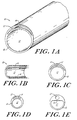
- FIGURE 1A is a schematic perspective view of
a bilumenal vascular prosthesis of the present
invention.
- FIGURE 1B is a schematic longitudinal
cross-sectional view of the embodiment of FIGURE 1A.
- FIGURE 1C, 1D and 1E show schematic
cross-sectional views of alternative configurations
of the bilumenal device of FIGURE 1A.
- FIGURE 2 shows a schematic front elevation
view of a die used in the manufacture of the
bilumenal device of FIGURE 1A.
- FIGURE 2A and 2B show schematic
cross-sectional views of the die of FIGURE 2 taken
along planes A-A an B-B, respectively.
- FIGURE 3 is a schematic side elevation view
of a bilumenal device in which the secondary lumen is
partially co-extensive with the primary lumen.
- FIGURE 3A is a schematic cross-sectional
view of the embodiment of FIGURE 3.
- FIGURE 4 is a schematic perspective view of
a multilumenal device of the invention.
- FIGURE 5 is a schematic longitudinal
cross-sectional view of an embodiment of the
invention having a preattached mini-pump.
- FIGURE 6A is a schematic perspective view of
an alternate multilumenal embodiment of the invention.
- FIGURE 6B is a schematic perspective view of
an alternate configuration of the embodiment of
FIGURE 6A.
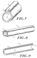
- FIGURE 7 is a schematic perspective view of
an alternate configuration of the multilumenal
embodiment of FIGURE 6A.
- FIGURE 8 is a schematic perspective view of
a self-sealing vascular tubular structure.
- FIGURE 9 is a cross-sectional view taken
along line 9-9 of FIGURE 8.
- FIGURES 10A and 10B are schematic
cross-sectional views of other embodiments of the
self-sealing vascular tubular structure of the
invention.
- FIGURES 11A, 11B and 11C show an exemplary
die for manufacturing by extrusion the vascular
tubular structure of the invention.
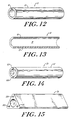
- FIGURE 12 is schematic illustration showing
a perspective view of an implantable bilumenal
vascular graft having a radiopaque material
integrated in one of the lumena.
- FIGURE 13 is schematic illustration showing
a perspective cutaway view of the vascular graft
shown in FIGURE 12 showing both lumena without the
radiopaque material.
- FIGURE 14 is schematic illustration showing
a perspective view of a trilumenal vascular graft of
the present invention in which the two small lumena
both contain a radiopaque material.
- FIGURE 15 is schematic illustration showing
a perspective view of a quadrilumenal embodiment of
the vascular graft of the present invention in which
the three small lumena all contain a radiopaque
material.
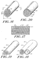
- FIGURE 16 is a perspective view of one
embodiment of a polylumenal prosthetic device
constructed in accordance with the teachings of the
present invention.
- FIGURE 17 is a cross section view taking
along line XVII-XVII of FIGURE 16.
- FIGURE 18 is a perspective view of another
embodiment of the prosthetic device of the present
invention.
- FIGURE 19 is a perspective view of still
another embodiment of the prosthetic device of the
present invention.
- FIGURE 20 is a perspective view of yet
another embodiment of the prosthetic device of the
present invention.
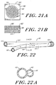
- FIGURES 21A and 21B are schematic views of a
die suitable for extruding a polylumenal prosthetic
device constructed in accordance with the teachings
of the present invention.
- FIGURE 22 is a schematic perspective view of
a bilumenal separable vascular prosthesis with a cap
at one end.
- FIGURE 22A is a schematic cross-section of
the embodiment shown in FIGURE 22 taken along axis
A-A.
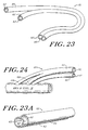
- FIGURE 23 is a schematic perspective view of
a bilumenal, separable prosthesis.
- FIGURE 23A is a schematic, enlarged
perspective view of the notched end of the embodiment
of FIGURE 23;
- FIGURE 24 is a schematic perspective view of
a bilumenal prosthesis attached to a blood vessel.
- FIGURE 25 is a schematic perspective view of
a bilumenal, separable, vascular prosthesis; and
- FIGURES 26-26A are schematic showing a
representative dilumenal prosthesis with a perforated
divisible wall between the tubes.
-
-
Like reference characters in the respective
FIGURES indicate corresponding parts.
Detailed Description of the Invention
-
In its broadest aspect, the invention
features a multi-lumenal prosthetic device for
implantation into a patient. The invention can be
utilized, for example, as a vascular graft providing
sustained release of a selected bioactive agent or
diagnostic material directly into a blood or other
fluid flow pathway. The device has at least two
lumena which are separated by a porous,
semi-permeable wall. In the case of the device being
used as a vascular graft, it is grafted onto a vein
or artery in an individual such that the primary
lumen becomes part of the individual's blood flow
pathway. The secondary lumen is filled with a
material such as, for example, a bioactive or
diagnostic agent and the porous wall between the
lumena allows the material disposed in the secondary
lumen to diffuse into the bloodstream flowing through
the primary lumen. As described in further detail
below, the device allows the release of the material
across the wall or membrane into the bloodflow
pathway in a controlled manner.
-
The device comprises a main, or primary
lumen, which is of a diameter sufficient to allow
blood flow appropriate for the artery or vein to
which it is attached to occur. Thus, the device has
the geometric configuration of a tube, open at least
at one end, and typically-at both ends. The open end
is sutured to an opening in the patient's
arteriovenous pathway, thus becoming an extension of
that pathway.
-
The device also contains at least one
secondary lumen adjacent to the first lumen. At
least one of the secondary lumena contains or is
adapted to contain the selected bioactive or
diagnostic materials. These materials can include,
for example, therapeutic or prophylactic agents, such
as a drug, protein, enzyme, antibody or other agent,
or cells which produce a drug, protein, enzyme,
antibody, or other agent. The diagnostic material
can include, for example, a radiolabeled antibody or
antigen.
-
In one embodiment of the invention, one or
more of the secondary lumena are pre-filled with the
bioactive material. For example, the pre-filled
secondary lumen can contain cells which secrete a
bioactive agent. As a variation of this embodiment,
another embodiment may include a pre-filled lumen in
conjunction with other secondary lumena into which
drugs or diagnostic materials are introduced after
implantation.
-
Specific embodiments of the device are
illustrated by the Figures. FIGURE 1A shows a
bilumenal tubular structure 10 having a first lumen
12 and a secondary lumen 12'. The first lumen 12 has
a structure sufficient for blood flow therethrough.
For a vascular graft, the diameter of this lumen 12
is generally the same or similar in size to the host
artery or vein to which it is grafted. As mentioned,
however, the structure 10 can be formed to
accommodate other types of fluid flow.
-
As shown in FIGURE 1B, the secondary lumen
12' is adjacent the first lumen 12, and is separated
by a semi-permeable, micro-porous, wall 14. The wall
14 has a permeability sufficient to allow diffusion
of the bioactive agents or diagnostic material of
choice from the secondary lumen 12' into the fluid
flow pathway defined by the first lumen 12. In a
multi-lumen arrangement, i.e., a device having more
than two lumena, the adjoining wall 14 lies in
communication between each of the secondary lumena
and the primary lumen. Alternatively, there can be a
semi-permeable wall between each secondary lumen 12'
and the first lumen 12, with an impermeable wall
among the secondary lumena.
-
The thickness and permeability of the wall
14 can be adapted to accommodate different drugs,
bioactive or bioinert agents, and the like, and to
control the rate at which the material disposed in
the secondary lumena 12' diffuses across the wall
14. Control over the release of the drug or agent
can be obtained by choosing appropriate molecular
weights, degrees of crystallinity and/or expansion
parameters in the polymer matrix forming the
structure 10. The wall 14 can be manufactured having
a predetermined permeability factor, and the
concentration of materials to be transported across
the membrane can be selected accordingly.
-
The opportunity to control the permeability
of the wall 14 is afforded during the extrusion and
expansion process as discussed in greater detail
below. By controlling the intermodal distance of the
polymeric matrix and properly selecting the specific
resin composition and expansion conditions, the
porosity of the wall 14 can be determined.
-
The outer diameter (OD) of the external wall
of the structure 10 is generally in the range of from
about 3 mm to about 30 mm. The internal diameter
(ID) of the primary lumen is generally from about 1mm
to about 28 mm depending upon the type of blood flow
through the prosthesis. The OD and ID vary according
to the type of pathway for which the prosthesis is
used. For example, arterial prostheses will
generally have OD of from about 6 mm to about 18 mm,
whereas venous prostheses will generally have an OD
of from about 12 mm to about 24 mm. The ID of the
secondary lumena 12' is generally from about .1 mm to
about 6 mm, depending upon the OD.
-
As shown in FIGURES 1C, 1D, and 1E, the
cross-sectional configuration of the lumena designed
in accordance with the invention can vary in size and
shape depending upon the specific application. In
FIGURE 1C, the secondary lumen 12' extends over
approximately one-third of the circumference of the
lumen 12. FIGURE 1D shows a diminished relative size
of the secondary lumen 12' with respect to the first
lumen 12, and FIGURE 1E shows a first lumen 12 having
an adjacent secondary lumen 12' of dimensions
sufficient only to transport substances of a few
microns in size. The relative size of the secondary
lumen 12' depends on the type of substance to be
transported through secondary lumen 12', and the
desired rate of diffusion across wall 14. The
permeability of wall 14 may be a factor in
determining the appropriate size of secondary lumen
12'.
-
In another aspect, the invention features a
method for delivering a bioactive agent or diagnostic
material directly to a patient's body fluid,
bloodstream or otherwise, in a controlled manner. In
the method, a surgeon or other qualified person,
surgically exposes the desired region of the patient
for introduction of the prosthetic device 10. The
desired site may, for example, be an area of
occlusion or weakness in the patient's
arteriovascular system. In such a case, during
interruption of the patient's blood flow the
prosthesis 10 is surgically implanted and sutured or
otherwise secured in place. Proper positioning of
the prosthesis 10 requires alignment of the primary
lumen 12 with the blood flow pathway such that the
blood flow is diverted through the primary lumen 12.
The secondary lumen 12' either contains or is filled
with a drug or agent of choice. The drug or agent
perfuses across the interlumenal wall 14 into the
bloodstream at a controlled and substantially
continuous rate. In this manner, the present
invention allows continuous administration of the
drug over a prolonged period of time similarly to
controlled release systems which deliver a drug at a
predetermined rate over a definite period of time.
-
In an example of use of the present
invention, an antibody which is specific to a protein
indicative of the presence of malignancy is
introduced into the vascular system of a patient
utilizing the present device and method. The device
10 is surgically implanted in a patient's vascular
system and blood flow is established through the
primary lumen 12. The antibody is added to the
secondary lumen 12' either before implantation by
pre-filling the lumen or after implantation by
injecting the antibody composition into the secondary
lumen. The antibody is labelled, for example, with a
remotely detectable radioisotope such as 125I. The
labelled antibody moves across the porous wall 14
between the primary lumen 12 and the secondary lumena
12' into the patient's blood flow pathway, which
flows through the primary lumen 12. Once in the
pathway, the labelled antibodies travel to the site
of the malignancy and bind at the appropriate protein
binding sites. The concentration of the radioisotope
at the target site can then be detected using an
appropriate detection device, e.g., a gamma camera.
Additional doses of the antibody composition can be
injected into the secondary lumen 12' through a
cannula, or through a pre-attached catheter which
communicates with the secondary lumen 12', without
directly invading the patient's bloodstream.
-
In another exemplary use of the present
invention, combinations of anti-coagulant platelets
and plasminogen activators, such as heparin, hirudin
and tPA can be injected into the secondary lumen 12'
to be released at a controlled, continuous, rate into
the bloodstream. Continuous release of a solution
containing either heparin, tPA, or combinations of
the two into a vascular graft area has been shown to
be effective in reducing occlusion from intimal
hyperplasia, while not resulting in whole body
systemic anti-coagulation. Clifton et al., Heart &
Lung, 199(1): 115-118 (March, 1991).
-
In another example of use of the invention,
the prosthesis 10 can be used for distribution of
chemotherapy agents which are often very toxic and
often cause arterial and venous blood vessel
destruction at the needle catheter entry site. A
major complication of such chemotherapy is the
constant risk of permanent, significant delivery site
complications such as infection or occlusion due to
thrombus formation at the vessel wall injury. The
high concentration of such toxic agents very often
has a deleterious effect on the blood vessel, further
complicating the healing required for the needle
tract or catheter injury incurred at the site of drug
infusion.
-
The device 10 eliminates such needle and
catheter injury to the blood vessel and large bolus
chemical exposure to the native vessel with these
highly toxic chemotherapy agents. Moreover, the
device 10 can be replaced if long term therapy causes
eventual failure or thrombus occlusion. A vein or
artery permanently destroyed by chronic therapy, on
the other hand, is irreplaceable. Similar problems
and corresponding solutions also exist for
hemodialysis patients whose native veins are consumed
by repetitive needle penetration and permanent blood
vessel wall injury.
-
The secondary lumen forming a chamber or
reservoir for a drug or other bioactive substance
need not be fluid-filled, but may be filled with a
solid or powder, which,upon perfusive exposure to
surrounding fluids, releases its active agent into
the fluids. In one aspect of the invention, a
substance is incorporated in a binder that is drawn
or extruded to form a wire or rod of active
materials, which is then cut to length and threaded
into the secondary lumen. Perfusion rate and dose
are carefully controlled by selection of a binder
material having the desired in vivo solubility and of
a wire gauge, selected to determine a desired total
amount of exposed surface area. In addition, the
solid wire or rod is cut to length, to determine the
total dose. The provision of medications in a
leachable or resorbable wire body in this manner is
thus seen to offer great simplifications over the
prior art techniques of medication or coating a
prostheses, which generally involved lengthy steps of
soaking and conditioning the graft material.
-
A method of practicing this aspect of the
invention includes providing a vessel or organ graft
prosthesis surgically implanted and spliced into a
vessel or organ, the graft prosthesis having one or
more included chambers in the form of lumena
extending along the graft, and providing one or more
string, rod or wire shaped solid pieces of a
treatment material in one or more of the lumena to
locally perfuse the material into the graft over an
extended time.
-
The tube structures of the invention can be
manufactured from any suitable biocompatible material
that can be arranged to form a microporous
structure. Polymeric materials which are useful for
this purpose include, for example, either expanded or
unexpanded polytetrafluoroethylene (PTFE), Dacron®
brand polyester, and other synthetic polyester fibers
such as mandrel spun polyurethane and silicone
elastomeric fibers. Also, copolymeric materials such
as described in U.S. Patent Nos. 4,187,390 and
4,973,609 can be utilized. These are materials made
up of more than one type of monomer and have
advantages as described in the cited patents, in some
applications. The structures can also be formed by
extrusion, form molding, or weaving using techniques
well known in the art.
-
In a preferred embodiment, the inventive
prosthesis is manufactured by paste forming and
rapidly stretching and/or expanding highly
crystalline, unsintered, polytetrafluoroethylene.
Paste forming by extrusion of PTFE is well-known in
the art. Generally, the steps in paste-forming
include mixing the resin with a lubricant, such as
odorless mineral spirits, and then forming the resin
by extrusion into shaped articles. The lubricant is
removed from the extruded article by drying,
following which the article is sintered by its being
heated above its crystalline melting point of
approximately 327°C. The sintered, unexpanded,
article is a relatively impermeable product. To
achieve a greater degree of permeability in the
finished product, however, the prostheses of the
invention can be formed from an unsintered resin.
-
Paste-formed, dried, unsintered, shapes can
be further treated by expanding and/or stretching
them in one or more directions under certain
conditions so that they become porous yet retain
their strength. Such stretching and expansion with
increased strength occurs with certain preferred
tetrafluoroethylene resins, e.g., PTFE. The porosity
of the material is affected by the temperature and
rate at which it is stretched and expanded. A method
for manufacturing porous PTFE tubing appropriate for
use in the present invention is described in detail,
for example, in U.S. patent 3,953,566, and U.S.
patent 4,973,609 the teachings of both of which are
hereby incorporated by reference herein.
-
Stretched and expanded PTFE is characterized
by a microstructure of nodes interconnected by small
fibrils. The space between the nodes and the number
of fibrils is controlled by changes in the
temperature and rate of stretching and expansion of
the PTFE, to produce tubing having predetermined
porosity and flex qualities. For example, products
which are stretched and expanded at high temperatures
and high rates have a more homogeneous structure,
i.e., they have smaller, more closely spaced nodes,
which nodes are interconnected with a greater number
of fibrils. While the resulting structure is
stronger than products stretched and expanded at
lower temperatures and rates, the porosity is also
reduced. Thus, by controlling these two factors, it
is possible to construct a series of tube structures
having a range of porosity within a desirable range
of strength.
-
Tube structures manufactured as described
above begin to lose their crystallites and the
crystallinity decreases above this temperature. This
is accompanied by a concomitant increase in the
amorphous content of the polymer. Amorphous regions
within the crystalline structure greatly inhibit
slippage along the crystalline axis of the
crystallite and lock fibrils and crystallites so that
they resist slippage under stress. Heat treatment
may be considered to be, therefore, an amorphous
locking process, which results in an increase in the
amorphous content and of the strength of the treated
structure. Heat treatment above 327°C has been found
to cause a two-fold increase in the strength of PTFE
is approximately 345°C, heat treatment is even more
effective. Similar results can be achieved at lower
temperatures if expose time is accordingly
increased. The optimum heat treating temperature is
generally in the range of from about 350°C to about
370°C, with heating periods in the range of from
about five seconds to about one hour. Other factors
upon which the strength the polymer matrix is
dependent upon include the strength of the extruded
material before expansion, the degree of
crystallinity of the polymer, the rate and
temperature at which the expansion is performed, and
amorphous locking.
-
The tube structures of the invention can be
formed using other paste-forming operations known to
those skilled in the art, for example, any of the
available molding processes. Resins other than PTFE
may also be used which are generally formable into
such tube structures, and which may result in
relatively fluid impermeable structures.
-
The prosthesis 10 can be coated on both the
interior lumenal and/or the exterior surfaces with a
biocompatible material to render it more hydrophilic
or hydrophobic, or to allow specific protein binding
or attachment after implantation. Coating materials
which are useful for this purpose include, for
example, various glycoproteins, albumin or polymeric
coatings often used for plasma polymerization, and
solvable polymeric coatings such as EVA and PVA Due
to the physiological properties of both the arterial
and venous system, however, it is important for the
prostheses 10 to be gas permeable, or selectively gas
permeable, to permit oxygen-carbon dioxide exchange.
However, even gas impermeable tube structures may be
useful as vascular grafts in certain anatomical
applications.
-
As stated, in the preferred embodiment, the
prostheses of the present invention are formed by
extrusion of PTFE which is performed using dies of
predetermined shape of the type known in the art.
FIGURES 1C through 1E, for example, show
cross-sectional views of prostheses of the invention
made using different exemplary dies. In particular,
FIGURE 2 schematically shows an exemplary die 50,
corresponding to the illustrated prosthesis of FIGURE
1A. The dies are manufactured from materials and
according to methods which are well known in the art.
-
Generally, and as is illustrated in FIGURE
2, the die 50 consists of a peripheral support
structure 56 encasing a first solid die-piece 52 for
forming a first lumen, and a second solid die-piece
54 proximal to the first die-piece 52 for forming a
secondary lumen. The specific spacing of the first
die-piece 52 from the second die-piece 54 depends on
the specific desired prosthesis configuration. As
best shown in cross-section in FIGURE 2A, the die 50
may include an external port 60 for introduction of
PTFE paste or the like for extrusion. FIGURE 2B
shows in cross-section the exemplary die 50 of FIGURE
2, showing aperture 58 for forming membrane (14 of
FIGURE 1) of the invention.
-
After the PTFE resin is formed, such as by
extrusion as discussed above, it is stretched and/or
expanded and then sintered while being held in the
stretched and/or expanded state. Stretching refers
to elongation of formed resin while expansion refers
to enlargement of the formed resin perpendicularly to
its longitudinal axis. The rate of stretching and
the stretch ratio affect the porosity of the finished
product in a predictable manner allowing a prosthetic
device to be produced having a specified porosity.
The rate of stretching refers to the percentage of
elongation per second that the resin is stretched
while the stretch ratio refers to the relationship
between the final length of the stretched resin and
the initial length of the stretched resin. For
example, stretching an extruded PTFE tube at a
stretch ratio of two to one and a stretch rate of
sixty results in a porosity of approximately forty.
This porosity is unitless and is determined as set
forth on page eighty-four of the American Society For
Testing of Materials' Special Technical Publication
Number 898. So, for example, based on stretch ratios
ranging from two to one, to six to one, a stretch
rate of sixty percent per second yields a porosity of
between approximately forty and approximately ninety,
a stretch rate of one hundred and forty percent per
second yields a porosity of between approximately
sixty and approximately eighty-five, and a stretch
rate of nine hundred percent per second yields a
porosity of between approximately sixty-five and
approximately eighty-five.
-
In addition to the porosity, the geometry of
the node and fibril network of PTFE can be controlled
during stretching and expansion. In the case of
uniaxial stretching, that is, elongation of the
formed PTFE resin along the direction of extrusion,
the nodes are elongated causing the longer axis of
each node to be oriented perpendicularly to the
direction of stretch. Accordingly, the fibrils are
oriented parallel to the direction of stretch. Axial
stretching, additionally includes expanding the PTFE
resin in the radial direction and can be utilized to
produce a prosthetic device having a composite
porosity. As in uniaxial stretching, the rate and
ratio of radial expansion affects the resulting
_porosity of the prosthetic device.
-
In one embodiment, the apparatus of the
present invention includes co-extruded plural lumena,
the secondary lumena 12' of which extend
substantially along the entire length of the first
lumen 12. In another embodiment of the invention,
however, as illustrated in FIGURE 3, the secondary
lumen 12' extends along only a portion of the first
lumen 12.
-
The illustrated prosthesis 10' of FIGURE 3
is structurally similar to the prostheses 10
described above. As shown in cross-section FIGURE
3A, the portion of the prosthesis 10' which includes
a secondary lumen comprises a microporous,
semi-permeable, wall 14 separating the secondary
lumen 12' with the first lumen 12. However, in this
illustrated embodiment, the secondary lumen only
extends along a predetermined portion of the
prosthesis 10'.
-
The embodiment shown in FIGURE 3 may be
manufactured in a manner similar to that described
above. The extrusion die for forming the
partially-extending lumen may be modified in a manner
known to those skilled in the art. For example, the
die used in the extrusion of this embodiment of the
invention may include a gate-type device which
enables selective opening and closing of an aperture
to coextrude a secondary lumen.
-
An alternative embodiment of the prosthesis
of the present invention is illustrated in FIGURE 4.
In the illustrated prosthesis 10', the first lumen 12
is essentially round, with the secondary lumen 12'
forming a polygonal configuration around the first
lumen 12. While this illustrated embodiment shows
three secondary lumen 12', other forms of the
invention may include fewer or more secondary
lumena. In addition, the apparatus of the invention
may have various overall geometric configurations,
depending upon the anatomical destination of the
prosthesis 10'.
-
An important aspect of the invention is the
introduction of a bioactive agent, pharmaceutical,
chemotherapy agent or diagnostic material into a
secondary lumen for perfusion into the blood flow
pathway of the patient as it is channeled through the
first lumen of the prosthesis. This introduction of
material may occur by including a mini-pump attached
to the secondary lumen of the prosthesis, for
example, by a catheter.
-
As shown in FIGURE 5, a mini-pump 20 may be
placed in communication with at least one of the
secondary lumen 12' for perfusion of a drug into the
secondary lumen 12'. The mini-pump 20 can be used to
deliver a predetermined amount of a drug at a
preselected rate to the secondary lumen 12.
Thereafter, the drug perfuses across the
microporous, semi-permeable, wall 14 and into the
bloodflow pathway of the first lumen 12. Mini-pumps
which may be used with the prosthesis of the
invention are commercially available. Some examples
are Alza Pump, Thermedics' Infusaid Pump, Medtronic's
Infusable Pump, and INFU•.DISKS™ (Electrochemical Drug
Delivery, Inc. San Diego, California) designed for
subcutaneous delivery of drugs or diagnostic agents.
The mini-pump 20 may be located externally to the
patient, or may be surgically subcutaneously
implanted.
-
As shown in FIGURE 5, the mini-pump 20
contains a drug reservoir 26 from which a connector
tube 24 extends. The connector tube 24 may either be
integral with the reservoir 26, or mechanically,
detachably connected to the reservoir 26. The
connector tube 24 extends from the reservoir 26 to a
secondary lumen 12' of a prosthesis 10. The
connector tube 24 may connect to the secondary lumen
12' by means of a mechanical attachment device 22, as
illustrated, or may be formed integral with the
secondary lumen 12'. Mechanical attachment devices
are well known in the art, and include luer-locks.
It is generally preferable that the mechanical
attachment device is such that the mini-pump may
readily be replaceable, thus attachment devices which
do not require the application of pressure are
preferable over pressure-lock devices.
-
Similarly, a mechanical pump, infusion
system, or other drug delivery system located outside
the host body may be attached for the delivery of a
drug or other bioactive material into a secondary
lumen. The drug delivery source may either be
integral with the secondary lumen, or may be
mechanically, releasably attached.
-
Alternate embodiments of the present
invention are shown in FIGURES 6A and 6B. In those
embodiments, the secondary lumena 12' form a raised
platform 30 to facilitate subcutaneous needle
access. Reservoirs 32 extend from the secondary
lumena 12' along the sides of the first lumen 12 to
provide a greater surface area for diffusion of the
drug across the microporous, semi-permeable, wall
14. As shown in FIGURE 6B, needle access ports 34
may be separated for extracutaneous identification of
the individual secondary lumena. In this manner,
separate drugs may be delivered to separate secondary
lumena.
-
Another embodiment of the prosthesis of the
present invention is shown in FIGURE 7, wherein
needle access ports 34 are located in a single raised
platform 30. In this illustrated embodiment, the
secondary lumena 12' do not include reservoirs that
extend along the sides of the first lumen 12. The
secondary lumena of the illustrated embodiment extend
either partially or fully along the length of the
first lumen.
-
In accordance with yet another aspect of the
invention, illustrated in Figures 8-11, the invention
relates to an implantable self-sealing tubular device
comprising at least two lumena. The device defines a
primary lumen adapted for blood flow therethrough and
at least one secondary lumen which contains a
non-biodegradable elastomeric material, and which
shares a common side wall with the primary lumen.
-
The device of the invention can be used as a
prosthetic vein, artery, pseudo-organ, or other
similar anatomical structure. In preferred
embodiment, the prosthesis comprises a vascular
graft. The device is implanted into the patient's
arterial or venous system so that blood is
established through the primary lumen.
-
The secondary lumen is filled with a
non-biodegradable elastomer which self-compresses
after puncture by a cannula or needle to seal the
puncture site. Elastomeric materials which are
useful for this purpose include elastomeric polymers
and copolymers, including silicone rubbers,
polyurethanes, and polyethers. Various
fluoropolymers are suitable as well.
-
One illustrative device embodying this
aspect of the invention is shown in FIGURE 8. The
device shown is a self-sealing vascular tubular
structure 110 formed of a body 112. The body 112
defines lumena 114 and 118 which share common side
wall 15. Disposed in the lumen 118 is a self-sealing
elastomeric material 116.
-
FIGURE 9 is a cross-sectional view of the
structure 110 in which it can be clearly seen that
the body 112 defines lumena 114 and 118. While in
FIGURE 9, the lumena 114 and 118 are of equal
lengths, it should be understood that the structure
110 will only have a self sealing capability along
the length which is coextensive with lumen 118.
-
In a preferred embodiment, lumen 114 is of a
sufficient internal diameter (ID) to allow blood flow
therethrough. This means the ID of the lumen 114
will typically be between about 3 mm and about 24 mm
depending on the application. Thickness of the
common side wall 115 is generally in the range of
between about 0.1 mm and 1.2 mm, depending upon the
type of blood flow through the prosthesis. The
thickness varies according to the type of pathway for
which the prosthesis is used.
-
As shown, in FIGURES 10 and 10B, the
cross-sectional configuration of the lumena designed
in accordance with the invention may vary in size and
shape depending upon the specific applications. In
FIGURE 10A, the secondary lumen 118 extends over
approximately one-third of the circumference of the
lumen 114. FIGURE 10B shows a diminished relative
size of the secondary lumen 118 with respect to the
first lumen 114.
-
In a preferred embodiment the tube
structures of the present invention are formed by
extrusion of PTFE. Extrusion is performed using dies
of predetermined shape according to principles known
in the art. FIGURE 11 schematically shows an
exemplary die 150, corresponding to the illustrated
prosthesis of FIGURE 8. The dies may be manufactured
from materials available and well known in the art.
-
Generally, as illustrated in FIGURES
11A-11C, the die 150 consists of an upper plate 156
and a lower plate 158. The upper plate 156 defines a
circular edge 157 corresponding to the other diameter
of the tubular structure 110. The lower plate 158
includes a first hub 154 proximal to the hub 152 for
forming a first lumen, such as lumen 114, and a
second hub 154 proximal to the hub 152 for forming
a secondary lumen, such as lumen 118. The specific
spacing of the first hub 152 from the second hub 154
depends upon the specific desired prosthesis
configuration. This spacing will dictate, for
example, the thickness of the common side wall 115.
As best shown in cross-section in FIGURE 11C, the die
150 typically includes a channel 160 for introduction
of PTFE paste, of the like, under pressure for
extrusion. The manufacture of such dies is
understood to be well known in the art.
-
After the PTFE resin is formed, such as by
extrusion as discussed above, it is stretched and/or
expanded and then sintered while being held in the
stretched and/or expanded state. Stretching refers
to elongation of formed resin while expansion refers
to enlargement of the formed resin perpendicularly to
its longitudinal axis. The rate of stretching and
the stretch ratio affect the porosity of the finished
product in a predictable manner allowing a prosthetic
device to be produced having a specified porosity.
The rate of stretching refers to the percentage of
elongation per second that the resin is stretched
while the stretch ratio refers to the relationship
between the final length of the stretched resin and
the initial length of the stretched resin. For
example, stretching an extruded PTFE tube at a
stretch ratio of two to one and a stretch rate of
sixty results in a porosity of approximately forty.
This porosity is unitless and is determined as set
forth on page eighty-four of the American Society For
Testing of Materials' Special Technical Publication
Number 898. So, for example, based on stretch ratios
ranging from two to one, to six to one, a stretch
rate of sixty percent per second yields a porosity of
between approximately forty and approximately ninety,
a stretch rate of one hundred and forty percent per
second yields a porosity of between approximately
sixty and approximately eighty-five, and a stretch
rate of nine hundred percent per second yields a
porosity of between approximately sixty-five and
approximately eighty-five.
-
In addition to the porosity, the geometry of
the node and fibril network of PTFE can be controlled
during stretching and expansion. In the case of
uniaxial stretching, that is, elongation of the
formed PTFE resin along the direction of extrusion,
the nodes are elongated causing the longer axis of
each node to be oriented perpendicularly to the
direction of stretch. Accordingly, the fibrils are
oriented parallel to the direction of stretch.
Biaxial stretching, additionally includes expanding
the PTFE resin in the radial direction and can be
utilized to produce a prosthetic device having a
composite porosity. As in uniaxial stretching, the
rate and ratio of radial expansion affects the
resulting porosity of the prosthetic device.
-
In one embodiment, the apparatus of the
present invention includes co-extruded plural lumena,
as shown in FIGURE 8, the secondary lumen 118 of
which extends substantially along the entire length
of the first lumen 14'. In another embodiment of the
invention 10', as shown in FIGURE 5, a secondary
lumen 18' extends along only a portion of the tubular
structure 10' which includes the secondary lumen 18
provides a self-sealing feature.
-
Otherwise, illustrated tubular structure 10'
of FIGURE 3 is structurally similar to the tubular
structure 110 shown in FIGURE 8. As shown in
cross-section in FIGURE 3A, the portion of the
structure 10' which includes a secondary lumen
includes a common side wall 15' between the secondary
lumen 18' and the main lumen 14'. In the is
illustrated embodiment, however, the secondary lumen
18' only extends along a predetermined portion of the
structure 10'.
-
The embodiment shown of FIGURE 3 can be
manufactured in a manner similar to that described
above. The extrusion die for forming the
partially-extending lumen may be modified in a manner
known to those skilled in the art. For example, the
die used in the extrusion of this embodiment of the
invention may include a shunt which allows selective
opening and closing of an aperture for coextruding a
secondary lumen.
-
The method of the invention comprises
utilizing the present self-sealing graft device to
replace or augment part of AV pathway in an
individual. In the method, a surgeon or other
qualified person surgically exposes the desired
region for introduction of the graft of the of the
invention. The desired site may be an area of
occlusion of weakness in the patient's
arteriovascular system, for example. An interruption
of the patient's blood flow is performed, and the
device is surgically implanted and sutured or
otherwise secured in place so that blood flow is
established through the primary lumen. Once the
graft is in place, the bloodstream can be accessed by
a cannula, intravenous needle or the like through the
secondary lumen. When the cannula or needle is
withdrawn, the elastomer on the secondary lumen will
compress thereby prevent blood from escaping from the
area of access.
-
In accordance with the further aspect of the
invention shown in Figures 12-15, a prosthetic device
such as a vascular graft, includes integral
diagnostic indicia for detecting the position or
patency of the graft by non-invasive external means.
The device is formed from a biocompatible tubular
structure which defines at least two lumena, a
primary lumen which is adapted for blood flow and at
least one secondary lumen within which a remotely
detectible component is disposed. The device of the
invention allows detection by x-ray, ultrasonic, MRI
and/or other non-invasive types of imaging. This
allows the position of the graft and/or the degree of
patency to be determined.
-
Various remotely detectible materials which
are generally known in the art are suitable for
disposition in the secondary lumen. For example,
radiopaque materials which are useful in the present
invention include barium sulfate and tantalum wire.
Also, barium filled elastomers, such as are used for
surgical sponges are suitable. Essentially, any
biologically inert metal-containing compound can be
used. Additionally, the secondary lumen can be
filled with a material having a different density
from that of the article itself which will enable
detection by ultrasonic and MRI techniques.
-
One embodiment of the present device is
shown in FIGURE 12. An implantable vascular graft
210 is formed of a tubular body 212 which defines a
lumen 214. Disposed in the perimeter of the article
212 is a remotely detectible component 216 such as
those discussed above.
-
FIGURE 13 shows a cross-section of the
vascular graft shown in FIGURE 12, with the
detectible component 216 removed. The FIGURE shows
an additional lumen 218. The detectible component
216 is disposed in lumen 218. The detectible
component 216 can occupy the entire lumen 218 or
merely a portion thereof depending upon the
requirements of the specific application.
-
FIGURE 14 shows another embodiment of the
present invention wherein an implantable vascular
graft 220 includes detectible components 216A and
216B disposed in the graft's body 212. In this
manner, by imaging after implantation, the effective
flow diameter of the graft 220 can be determined
since it is clearly related to the distance between
the detectible component 216A and the detectible
component 216. In this embodiment of the invention,
in addition to the flow-providing lumen 214, the body
212 defines two lumena for accommodating the
detectible components 216A and 216B.
-
Still another embodiment of the invention,
shown in FIGURE 15, includes an implantable vascular
graft 230 having a body 212 which defines a
flow-providing lumen 214 and in which are disposed
three detectible components 216A, 216B and 216C.
Still other embodiments of the invention will be
readily apparent to those ordinarily skilled in the
art.
-
The method according to the just described
aspect of the invention is practiced by implanting in
a patient a vascular graft as described above to
promote flow through a damaged or dysfunctional
pathway. In this method, the graft is implanted in a
patient such that blood flow is established through
the primary lumen of the device. The secondary
lumena contain the detectible material. By then
examining the graft by x-ray, MRI, or other form of
imaging, depending upon the type of material disposed
in the secondary lumen, the position, and effective
flow diameter of the graft can be determined.
-
For example, in the case of a graft having a
single line of detectible material co-extensive with
the graft, the surgeon can follow the line of the
graft, e.g., to ascertain whether the graft has
become twisted, looped or otherwise not properly
positioned during the surgery. In another
embodiment, a graft having two or more secondary
lumena which are filled with detectible material is
implanted. The doctor can then monitor blood flow
through the graft by observing through x-ray or MRI
imaging, the movement of the detectible lines
relative to each other. For example, a fluoroscopic
examination by a physician would reveal pulsation of
the graft vessel as the detectible lines would
constantly move in and out with respect to one
another; whereas if blood flow is stopped, no
movement will be observed. By using detectible lines
which are co-extensive with the graft, the openness
of the graft along its entire length can be
observed. Another advantage to the present invention
is that the detectible material is an integral part
of the graft, therefore, it cannot become separated
or dissociated from the graft after implantation.
The present method of monitoring an implanted
vascular graft is, therefore, more reliable than
traditional methods involving the suturing of
radiopaque markers to a vein, artery, or graft.
-
The foregoing description sets forth
advantageous properties of a lumenal prosthetic
structure for drug delivery, visualization of
patency, sealing and other desirable attributes. In
accordance with a further aspect of the invention
shown in Figures 16-21, the invention features an
implantable device formed of a microporous body
material which defines a multiplicity of coextruded,
molded, or otherwise formed capillary lumena and an
outer boundary or wall which circumscribes the
lumena. In FIGURE 16, an embodiment of the invention
is shown wherein a polylumenal device 310 is formed
of an implantable body 312. The body 312 defines a
multiplicity of lumena 314 for transporting fluid
flow. The outer diameter of the implantable device
310 is indicated as D while the diameter of a typical
capillary lumen is indicated as d. Specific values
of these characteristics are discussed in greater
detail herein below. As described in greater detail
below, the device 310 can be formed by any number of
paste forming methods such as by, for example,
extrusion.
-
FIGURE 17 is a cross-sectional view of the
implantable organ 310 and shows that in this
embodiment of the invention the capillary lumena 314
extend the entire length of the device 310 is
channeled through the lumena 314 for its entire
course. In another embodiment of the invention,
however, the lumena 314 do not extend along the
entire length of the device 310.
-
In either case, however, the device 310 has
the further property that its structural material has
a sufficiently microporous to allow communication of
cells and extra-cellular fluid in a direction
transverse to the capillary axes. This communication
allows cell processes to penetrate the structural
material. It also allows the selective trans-lumenal
passage of extracellular matter, such as marker
chemicals governing cell or organ growth patterns.
-
In addition to providing a more delicate
ultrastructure to encourage cell motility, one
advantage afforded by the capillary lumena structure
of the device 310 is realized, for example, when the
device 310 is utilized as a vascular graft.
Increased blood contact surface area 315 makes the
device 310 more conducive than known implantable
organs having only a single lumenal surface to
harboring endothelial cells. This is as a result of
the device 310 providing reduced shear pressure on
fluid flowing through the lumena 314.
-
Other advantages of the multiple capillary
lumena structure include improved cellular
distribution for blood contact and more surface area
for supporting the growth of more specialized cell
types. Furthermore, the porosity of the body 312
allows perfusion of necessary bioactive and
pharmaceutical agents for cell growth, and cell to
cell membrane contact necessary for cell metabolism,
replication, and subsequent replacement after cell
death. Generally, endothelial cell growth is
stimulated by several factors, including the binding
or adhesive action of glycoproteins such as
fibrinection. When the implantable device is
precoated with a glycoprotein, therefore, there is an
improvement in adhesion of seeded cells, increasing
retention and migration of cells during cell growth.
-
Another advantage of the capillary lumena
structure of the device 310 is that relatively small
flow channels provide a more desirable shear blood
flow characteristic than do large flow channels. As
a result, the survival of naturally occurring
endothelial cells is enhanced which stays the
proliferation of smooth muscle cells into the flow
channels. This is significant because, as discussed
above, smooth muscle cell proliferation has been
clinically identified as a common obstacle inhibiting
long term or extended patency of single lumen
vascular grafts. By inhibiting the proliferation of
smooth muscle cells by creating a more natural flow
environment through the capillary lumena 314,
therefore, the device 310 is capable of remaining
patent for an extended period of time, longer than
known single lumen grafts constructed of the same
structural material.
-
For a lumen to accommodate the flow of blood
cells, its diameter must be at least approximately
0.5 mm. So, to ensure blood flow while
simultaneously providing desirable shear
characteristics, the diameter d of the device 310
when used as a vascular graft is preferably between
0.5 mm and 6 mm, depending on the anatomical and
fluid flow requirements. As a result, as used
herein, the term capillary, when referring to the
lumena 314 of the device 310, generally means lumena
having an internal diameter ratio of at least 0.5 mm
I.D. for O.D.'s of 3 mm, 1 mm I.D. for O.D.'s of 6
mm, and 5 mm to 6 mm I.D. for O.D.'s of 30 mm. It
can be seen, therefore, that the ratio of lumena
inner diameter to the overall outer diameter of the
device is typically approximately one to six.
-
In addition to encouraging improved
harboring of naturally created and/or autogenously
cultured and seeded endothelial cells, the increased
surface area 315 provides more area for deposition
and growth of naturally occurring or seeded
genetically enhanced cell types in addition to
providing more surface area for bioactive and
pharmaceutical fluid and cell interface or contact.
-
For example, the following chart lists
typical pharmaceutical agents appropriate for either
coating on the walls of the lumena 314 of the
device
310 or filling selected lumena. A combination of the
two techniques may be desirable as well. Also
included in the chart is the desired effect achieved
by the listed pharmaceutical.
| Drug Class | Biological Activity |
| Steroids | Antiinflammatory, Antiproliferatory for SMC |
| Ibuprofen (non-steroid) | Antiinflammatory |
| Trombin Inhibitors | Reduce Acute Platelet Thrombosus |
| -Haparin | Antiproliferatory for SMC |
| -Hirudin | Thrombin Inhibition |
| Citrates | Anticoagulant |
| Antibiotics | Infection Protection, Prevention, Reduction |
| Glycoproteins/ Fibronectin | Promotes specific cell attachment to foreign material |
| Angiotensin | Enzyme Inhibitor |
| Cyclosporin | Immuno Suppressive Activity |
| γ-Interferon | Immuno Suppressive Activity |
| Angiopeptin | Antiproliferatory for SMC |
| Trapidil | Antianginal Agent, Vasodilator, Antiplatelet Activity |
| Colchicine | Antimitotic, Antisecretory Property |
| Dipiridymole | Antiplatelet |
| Salicylic Acid | Antiplatelet, Inhibits Thromboxane A2 Production (TXA2) |
| PGI2 (Protaglandin I2) | Antiaggregation and Vasodilation |
| TRA (Thromboxane Receptor Antagonists) | Blocks TXA2 Receptors without inhibiting PGI2 production |
| Nitric Oxide | Relaxes smooth muscle cells, potent antiplatelet aggregating substance |
| Five Types of Plasminogen Activators | Thrombolytic agents - potent clot dissolvers |
| 1. Steptokinase |
| 2. Acylated Steptokinase Plasminogen Activator Complexes(APSAC) |
| 3. Urokinase |
| 4. Single-Chain Urokinase Plasminogen Activator (scu-PA) |
| 5. Tissue Plasminogen (t-PA) |
| Combinations of Tissue Plasminogen Activator and Thrombin Inhibitors (i.e., T-PA and Hirudin) | Treatment of acute vascular graft thrombosis, or prevention of same |
| Lovastatin | Antiproliferatory for SMC |
| Cytotoxic Agents | Various, tumor specific chemotherapy agents |
| Insulin | For treatment of diabetes mellitus |
| Beta Blockers | For treatment of arrhythmia |
-
In FIGURE 18 there is shown an embodiment of
the invention wherein an implantable device 330 is
formed of an implantable body 332 which defines a
plurality of capillary lumena 334. In accordance
with the device 330, however, one end 336 defines the
capillary lumena 334 while another end 338 defines
only a single lumen 335. This embodiment of the
invention is well suited for artery to vein grafting
wherein the end 336 defining the lumena 334 is
connected to an artery of a patient while the end 338
defining only single lumen 335 is connected to a vein
of the patient. As a result, the ability of the
capillary lumena defining end 336 to prevent arterial
steal syndrome is exploited.
-
Arterial steal occurs when an equivalent
size lumen device is bypassed from an originating
artery to a lower pressure vein. Under such
circumstances, arterial flow can preferentially flow
through the bypass device in the vein, thereby
reducing flow pressure to the distal destination of
the originating artery. Hence the term arterial
steal, which is an undesirable effect when creating
such arterio-bypass shunts. When a multilumenal
device is used for such arterio-venous bypass or
shunting, the increased flow resistance of the
smaller lumens do not allow unrestricted flow,
therefore, preventing arterial steal from occurring.
-
Another embodiment of the invention is shown
in FIGURE 19 wherein a implantable device 340
incorporates a capillary lumena structure 344
circumscribed by an outer wall or boundary 342 having
a D-shaped profile. This broader, flatter structure
provides better needle access and is less conspicuous
in situations in which the device is implanted close
to the surface of a patient's skin. Note also that
the infra-structure of the device 340 provided by the
walls of the lumena 344 provides improved internal
strength for confronting the deleterious effects of
repeated needle access. That is, the implantable
organ of the invention will withstand more needle
punctures without aneurysm formation blowout, than
well known single lumen vascular grafts which succumb
to such undesirable events.
-
Still another embodiment of the invention is
shown in FIGURE 20 which shows a prosthetic device
350 that includes, in addition to a plurality of
capillary lumena 354, a larger lumen 356 located just
under the surface of the outer wall 352. This larger
lumen 356 is suitable for containing, for example,
either a self-sealing elastomeric material for
providing the device 350 with self sealing capability
or a bioactive material such as a pharmaceutical
agent. The larger lumen 356 enhances the device's
ability to deliver bioactive material to a patient's
blood stream through the microporous structure,
directly into the blood or body fluids flowing
through the multiple capillary lumens.
-
As noted above, the prosthesis of the
invention can be manufactured from any suitable
biocompatible material, such as PTFE, Dacron®, or
other synthetic polyester, or mandril spun
polyurethane or silicone elastomer micro-fibers that
can be arranged to form a microporous structure.
Hybrid constructions of these same materials are
suitable as well. Also, copolymeric materials such
as described in U.S. Patent Nos. 4,187,390 and
4,973,609 can be utilized. These are materials made
up of more than one type of monomer and have
advantages, in various applications, described in the
cited patents. The structures may be extruded, form
molded, mandrel spun fiber, or woven using techniques
well known in the field. In a preferred embodiment,
described in further detail below, the implantable
device is manufactured from stretched and/or expanded
PTFE tubing by rapidly stretching highly crystalline
unsintered polytetra-fluoroethylene in one or more
planes or axes.
-
Stretched and expanded PTFE is characterized
by a microstructure of large nodes interconnected by
fibrils, with the space between the nodes, internodal
distance, and the number of fibrils controlled by
changing the temperature and rate of expansion of the
PTFE to produce structures having predetermined
porosity and flex qualities. Internodal distances of
from smaller than approximately 0.5 microns to as
large as approximately 60 microns are suitable for
use with the present invention.
-
Products which are expanded at high
temperatures and high rates have a more homogeneous
structure, i.e., they have smaller, more closely
spaced nodes, which nodes are interconnected with a
greater number of fibrils. While the resulting
structure is stronger than products expanded at lower
temperatures and rates, the porosity is also
reduced. Thus, by controlling the two factors, it is
possible to construct a series of tube structures
having a range of porosity within a desirable range
of strength.
-
It has been noted that when tube structures,
manufactured as described above, are heated to above
the lowest crystalline melting point of the PTFE,
disorder begins to occur in the geometric order of
the crystallites and the crystallinity decreases.
This is accompanied by a concomitant increase in the
amorphous content of the polymer. So formed
amorphous regions within the crystalline structure
greatly inhibit slippage along the crystalline axis
of the crystallite and lock fibrils an crystallites
so that they resist slippage under stress. Heat
treatment may be considered to be, therefore, an
amorphous locking process, the important aspect of
which is an increase in the amorphous content of the
treated structure. In fact, heat treatment above
327°C has been found to cause a two-fold increase in
the strength of PTFE tubular structures.
-
As stated, in the preferred embodiment the
tube structures of the present invention are formed
by extrusion and expansion of PTFE. Extrusion is
performed using dies of predetermined shape which is
determined by considerations known in the art.
FIGURES 21A and 21B schematically show an exemplary
die 360, corresponding to the illustrated prosthesis
of FIGURE 16. The die may be manufactured from
materials available and well known in the art.
-
Generally, and as illustrated, the die 360
consists of an upper plate 362 and a lower plate
364. The upper plate 362 defines a circular edge 363
corresponding to the outer diameter of the tubular
structure 310. The lower plate 364 defines a
plurality of finger-like projections 366
corresponding to the lumena 314 of the prosthetic
device 310. The specific dimensions of the
projections 366 and their spacing from one another
depend upon the specific desired prosthesis
configuration. This spacing will dictate, for
example, the thickness of the common side walls 315.
As best shown in cross-section in FIGURE 21B, the die
360 typically includes a channel 368 for introduction
of PTFE paste, or the like, under pressure for
extrusion. In practice, the extruded material is
supported or carried as it exits the die, so that
tensile or compressive forces are controlled and the
capillary passages remain open. As discussed above,
the material may then be subjected to heat or other
treatment for sintering, solvent removal or the like.
-
After the PTFE resin is formed, such as by
extrusion, it is stretched and/or expanded and then
sintered while being held in the stretched and/or
expanded state as discussed above.
-
The invention contemplates that in various
embodiments the prosthesis may serve not only as a
flow structure, but as a matrix and support upon
which cellular matter is grown while blood circulates
therethrough. For these embodiments, the device may
be prepared and seeded with culturable cells, e.g.,
marrow or organ cells, or endothelial cells which
have been genetically modified to produce a desired
bioactive material, and may then be implanted in an
organ or connected to the AV system. Examples of
typical cell types useful for this purpose and their
corresponding biologic activities follow.
| Cell Type | Biologic Activity |
| EC (Endothelial Cells) | Endothelial cells line the blood contacting surface of all organs of the body and produce many initiators and inhibitors involved in wound healing, thrombosis, thrombolysis and blood vessel regeneration and cell growth, for direct perfusion into blood stream |
| Islets of Langerhans | Islet Cells produce insulin on demand, based on complex receptor blood sugar chemistry. |
| Pancreatic Cells | directly into the blood stream by the islet cells |
-
For these embodiments, the spacing between
capillaries is preferably small, and may approach
membrane thickness in places, to allow communication
by direct physical processes or by fluid mediators
between cells growing in different capillaries. The
body of the prosthesis thus provides a first
plurality of capillary channels for direct physical
flow of flood for supplying nutrients to living
tissue growing on the capillary walls, and a second
set of transverse pores or openings of substantially
smaller size for communication between cells, so that
they may flourish in a three-dimensional matrix. The
relatively open or microporous matrix is expected to
allow cellular material to grow into micro structures
which are similar to those of the structures in which
the parent cells naturally occur, thus providing an
effective environment for in vivo culture of
specialized cell types. As such, it offers the
prospect of providing an effective form of organ
replacement or supplemental therapy.
-
In an another embodiment, specific
autogenously derived and genetically engineered
growth factors can be inoculated into various lumena
for body fluid contact. Such growth factors are
specific proteins borne by flood platelets that
trigger tissue healing.
| Protein Class | Biologic Activity |
| PDGF Protein (Platelet derived growth factor) | Wound healing factor, encourages growth of new blood vessels |
| EGF (Epidermal Growth Factor) | Promotes wound healing, healing of ulcers reduced degradation and faster recovery of transplanted organs |
| bFGF (basic fibroblast growth factor) | Signals subdermal tissue growth, promotes blood vessel growth, bone graft growth |
| TGFb (transforming growth factor Beta) | Promotes wound healing of ulcers caused by varicose veins and diabetic ulcers |
| Erythropietin | Promotes red blood cell growth |
| GCSF (Granulocyte colony Stimulating factor) | Promotes white blood cell growth |
| GMCSF (Granulocyte macrophage colony Stimulating factor) | Promotes white blood cell growth |
| Iamin (Tripeptide) | Attracts and triggers various cell specific growth factors following trauma |
| BGF-1 (Heparin-binding growth factor-1) | Stimulates blood vessel growth |
| CD4 Protein | Controls growth of AIDS virus |
-
In accordance with a further aspect of the
invention shown in Figures 22-26, a vascular
prosthesis includes two or more tube structures
defining lumena of various diameters for
accommodating the flow of fluid, such as blood,
therethrough, wherein each of the tube structures is
manually separable from the others during surgical
introduction of each prosthesis. This allows each
tube structure to be used as a separate prosthesis at
least one end of each extending to a different
vascular site.
-
In addition to use as a vascular graft, one
or more of the lumena may be used for fluid flow of a
different nature, such as an organ-to-organ fluid
channel, or as a vehicle for drug delivery as
described above. The materials used in the
construction of the tube structures can be
semi-permeable to agents of specific sizes to allow
communication of the fluid or drug with the blood
flow of an adjacent tube structure. A multi-lumenal
vascular graft having drug delivery capability is
described in greater detail above, and will not be
discussed in further detail here, but it is
understood that the present aspect of the invention
includes all forms of hybrid vessel/drug delivery
combinations, and combinations with other aspects of
the invention described above. To prevent osmosis of
a drug or agent from a filled lumen to the
surrounding tissue, the external surface of the tube
structures, or the internal walls surrounding the
lumena can be coated with a non-permeable,
biocompatible material.
-
The internal diameter (ID) of each lumen
depends upon the intended use for each tube
structure. In general, lumena having ID's of from
about 3 mm to about 24 mm are useful as vascular
grafts. For example, a tube structure intended for
insertion in an arterial pathway can have a lumen ID
of from about 6 mm to about 18 mm. A tube structure
for insertion in a venous pathway can have a lumen ID
of from about 12 mm to about 24 mm. The lumena can
each have the same or different diameters for
insertion into one or more types of pathways. For
example, the lumen ID of tube structures to be used
as arterial grafts is generally less than the ID
lumen for use in venous grafts.
-
The outer diameter (OD) of the tube
structures is generally not related to the internal
lumen diameter. For example, in an embodiment of the
invention having two tube structures, the external
diameter of both tube structures can be the same,
while the internal lumen diameter of each tube may
differ.
-
The thickness of the lumen walls will vary
depending on the type of vascular graft. Generally,
an arterial graft has a thicker wall than a venous
graft. However, the exact dimensions depend on the
specific purpose. For manufacturing purposes, the
die used for extrusion may be varied to achieve walls
having the desired thicknesses. Wall thicknesses of
from about 0.1 mm to about 1.2 mm are useful for a
general range of vascular graft applications.
-
The tube structures are joined by a wall
which allows them to be easily separated. In various
embodiments of the invention, the tube structures are
separated either by pulling them apart or by cutting
them with scalpel or scissors. To facilitate
separation, the tube structures are joined by a small
bead or seam of material. The bead or seam serves to
hold the tubes together while allowing them to be
pulled or cut apart without impairing the wall
structure at the line of separation. In another
embodiment, the tubes are joined by a thickened wall
portion which, when separated, forms two walls so
that separated tube structures have walls of
substantially equal thickness.
-
In another embodiment of this aspect of the
invention, one or more of the tube structures
includes identifying markings. These markings can be
in the form of lines, dots, or other designs running
along the entire or partial length of the exterior
surface of each tube structure. These markings
distinguish the tube structure from that of the
adjacent tube, and may further act as codes
indicating, for example, the size of the inner
lumen. The different markings allow the user to
trace each tube structure should it become twisted
during use. The identification markings allow the
surgeon, or other user of the invention, to implant
the structure at one point along the arteriovenous
pathway, then thread it to a distal point while at
the same time being able to distinguish one tube
structure from the others.
-
For example, the point of origin for the
venous graft may be in the greater saphenous vein,
another graft may originate in the adjacent femoral
artery, and the point of insertion for the structure
is the anterior tibial vein and artery,
respectively. In traversing the patient's leg, it
would be easy for a surgeon to twist or otherwise
lose track of which structure involved venous
bloodflow and which structure transported oxygenated
blood. Thus, labelling the exterior surfaces of at
least one of the tube structures facilitates
distinction between the structures, reducing the risk
of error and extended surgical time.
-
In another embodiment of this aspect of the
present invention, the lumen walls are pretreated
with an agent to reduce the risk of occlusion of the
graft. For example, glow discharge coatings and
plasma polymerization methods such as are taught by
U.S. Patent No. 4,632,842 to Karwoski et al., impart
a property to the flow surface that will reduce or
prevent smooth muscle cell build-up within the
lumen. The walls can also be pre-coated, for
example, with a gelatin or a "time-release" agent
that releases small, localized amounts of
anticoagulant to the graft site.
-
The present tubular devices can be
manufactured from various biocompatible material.
For example, Teflon® brand polytetrafluoroethylene
(PTFE), in both its expanded and unexpanded forms, is
suitable for use with the invention. Polymer alloys
are suitable as well. Dacron® brand polyester fiber,
mandrel spun polyurethane, and silicone elastomer
fibers are also well suited for use with the
invention. Moreover, copolymeric materials such as
described in U.S. Patent Nos. 4,187,390 and 4,973,609
can be utilized. These are materials made up of more
than one type of monomer and have advantages, as
described in the cited patents, in some
applications. In a preferred embodiment, the tube
structures are manufactured from (PTFE) which has
been stretched and/or expanded as described in detail
above.
-
Referring now to the Figures, one embodiment
of the device is shown in FIGURE 22, in which the
tube structures 410 is joined at one end by a
terminal cap assembly 414 with fluid flow through
each lumen 412. The tube structures 410 can include
a notch near the fused, terminal end of the
structures 410 to direct fluid flow through each
lumen. The terminal cap assembly 414 is made of any
suitable biocompatible material. The terminal cap
assembly 414 can optionally be removable to
facilitate certain procedures, e.g., thrombectomy.
In that example, an incision is made away from the
anastoma and needle access area, thereby allowing the
clot to be removed without disrupting the intact
graft and fluid flow through the lumena.
-
In the embodiment shown in FIGURE 22A, the
tube structures 410 share a divisible wall structure
416 which has a thickness sufficient to allow a user
of the apparatus 100 to tear one tube structure 410
apart from another 410' without affecting the
integrity of either tube structure. The tube
structures can optionally include a built-in stop-gap
418, which prevents a user from dividing the tube
structures beyond the point of structural integrity.
-
The device 410 can be straight, and
relatively rigid, as shown, by example, in FIGURE 22,
or can be flexible for configuration in a variety of
functional modes, as shown, by example, in FIGURE
23. In that embodiment, the device 100 includes two
separable tube structures 410, 410' of relatively
flexible structure which can be used for multiple
arteriovenous applications. In the embodiment shown
in FIGURE 23, the two lumena 412 are of the same
diameter for use as a multiple vein return, used, for
example, to relieve arterial steal syndrome.
-
As illustrated in FIGURE 23A, the device can
include a divider notch 420 to direct blood flow
through the lumena 412 and 412'. The notches can
have various configurations, including a V-shaped
notch, a rounded notch, or other configurations as
may be desirable based on the specific location of
the prosthesis and the type of fluid flow desired by
the user.
-
Another embodiment of the present invention
is illustrated in FIGURE 24. In that embodiment, the
device 100 includes pre-divided tube structures 410a
and 410b at the proximal end, instead of a terminal
end cap. This embodiment of the invention can be
used to graft two or more vessels 30 to feed into one
or more lumena.
-
The extrusion can be performed using dies of
predetermined shape using principles known in the
art. FIGURES 2 , and 2A and 2B show three orthogonal
cross-sectional views of an exemplary die which can
be used in the manufacture of a device of the present
invention.
-
Generally, and as illustrated, the die 50
consists of a peripheral support structure 56
encasing a first solid die-piece 52 for forming a
first lumen, and second solid die-piece 54 proximal
to the first die-piece 52 for forming a secondary
lumen. The specific spacing of the first die-piece
52 from the second die-piece 54 depends upon the
specific desired prosthesis configuration. As best
shown in the cross-section in FIGURE 2A, the die 50
may include an external port 60 for introduction of
PTFE paste, or the like, for extrusion. FIGURE 2B
shows in cross-section the exemplary die 50 of FIGURE
2, showing aperture 58 for forming membrane (418 of
FIGURE 22) of the invention. The manufacture of such
dies is understood to be well known in the art.
-
Another embodiment of the invention is
illustrated in FIGURES 26 and 26A. FIGURE 26 shows a
dilumenal structure 100 having tube structures 410
and 410' joined by a divisible wall 416 which has
perforations 424 therein to facilitate separation of
the tubes 410 and 410'. FIGURE 26A shows the tubes
410 and 410' partially separated.
-
In operation, the surgeon surgically exposes
the desired region for introduction of the vascular
prosthesis of the invention. The desired site may be
an area of occlusion or weakness in the patient's
arteriovascular system, for example. An interruption
of the patient's blood flow is performed, and the
surgeon manually separates the tube structures from
each other, tearing along the common wall to the
desired stop point. Thus, a single divided vascular
prosthesis is surgically implanted and sutured or
otherwise secured in the desired location. Proper
positioning of the prosthesis requires alignment of
the lumen with the appropriate blood flow pathway
such that the patient's blood flow is diverted
through a lumen of the prosthesis. The same
procedure is then repeated for the other lumena of
the prosthesis, or the extra lumen can be tied off
and remain unused.
-
It should be understood that while several
embodiments of the invention have been described in
detail, the invention may be embodied in other
specific forms without departing from the spirit or
essential characteristics thereof. The present
embodiments are therefore to be considered in all
respects as illustrative and not restrictive, the
scope of the invention being indicated by the
appended claims rather than by the foregoing
description, and all changes coming within the
meaning and range of equivalency of the claims are
therefore intended to be embraced therein.
-
Embodiments of the invention may include the
features of the following enumerated paragraphs
("paras").
- 1. An implantable prosthetic device for
sustained release of a bioactive material into a
fluid flow pathway of a patient comprising
a body adapted for attachment to said fluid
flow pathway, said body defining
- (a) a primary lumen for accommodating fluid
flow therethrough, and
- (b) at least one secondary lumen
constituting a chamber at least a portion of
which is separated from said primary lumen
by a permeable wall permitting a bioactive
material disposed in said lumen to permeate
through said wall and into said primary
lumen.
- 2. A device as set forth in para 1 wherein
said bioactive material is a leachable strand of
solid material.
- 3. The device of para 1 further comprising a
means for delivering the bioactive material from an
external source into said at least one secondary
lumen.
- 4. The device of para 3 wherein said delivery
means comprises a biologically activated pump.
- 5. The device of para 3 wherein said deliver
means comprises a mechanical pump.
- 6. The device of para 5 wherein at least one
secondary lumen is filled with said bioactive
material prior to implantation.
- 7. An implantable prosthetic device for
delivering a bioactive material into a blood vessel
of a patient, the device comprising
a tubular body adapted for attachment to a
blood vessel of the patient, said body defining
- (a) a primary lumen for accommodating blood
flow therethrough, and
- (b) at least one secondary lumen at least a
portion of which constitutes a chamber which
extends along and is separated from said
primary lumen by a microporous wall, said at
least one secondary lumen being adapted for
containing a bioactive material for
permeating through said microporous wall
into said primary lumen.
- 8. A device as set forth in para 1 or 7
wherein said fluid flow pathway is a blood flow
pathway.
- 9. A device as set forth in para 1 or 7
wherein said fluid flow pathway is an organ to organ
flow pathway.
- 10. An implantable prosthetic device for
delivering a bioactive material into a blood vessel
of a patient, the device comprising
a tubular body consisting of
polytetrafluorethylene and adapted for attachment to
a blood vessel of the patient, said body defining
- (a) a primary lumen for accommodating blood
flow therethrough, and
- (b) a secondary lumen constituting a
chamber at least a portion of which is
separated from said primary lumen by a
microporous wall, said secondary lumen being
adapted for containing a bioactive material
for permeating through said microporous wall
into said primary lumen.
- 11. A method for delivering a bioactive material
to a fluid flow pathway of a patient, the method
comprising the steps of
providing an implantable prosthetic device
adapted for surgical connection to the fluid flow
pathway, the device comprising
- a body defining a primary lumen for
accommodating fluid flow therethrough, and
at least one chamber adjacent said primary
lumen, each chamber constituted by a
secondary lumen at least a portion of which
is separated from said primary lumen by a
microporous wall,
- surgically grafting said prosthetic device
to the fluid flow pathway in the patient to establish
fluid flow through said primary lumen, and
- introducing said bioactive material into at
least one of the secondary lumena thereby allowing
the material to permeate at a controlled rate through
the microporous wall into the fluid flow pathway.
- 12. A method as set forth in para 11 wherein
said step of introducing said bioactive material in
to said at least one secondary lumena comprises
pre-filling at least one of said at least one
secondary lumen with said bioactive material prior to
said grafting step.
- 13. The method of para 11 further comprising
the step of coating an exterior surface of said tube
with a biocompatible material.
- 14. The method of para 11 further comprising
the step of attaching to at least one of the
secondary lumena, means for delivering the bioactive
material to said at least one secondary lumen.
- 15. A method as set forth in para 11 wherein
said fluid flow pathway is a blood vessel.
- 16. A method for delivering a bioactive material
to a patient's bloodstream, the method comprising the
steps of
providing an implantable prosthetic device
adapted for surgical connection to a blood vessel of
the patient, the device comprising
- a tubular body consisting of
polytetrafluoroethylene and defining a
primary lumen for accommodating blood flow
therethrough, and a secondary lumen
constituting a chamber at least a portion of
which is separated from said primary lumen
by a microporous wall,
- surgically grafting said prosthetic device
to a blood vessel of the patient to establish blood
flow through said primary lumen, and
- introducing said bioactive material into the
secondary lumen thereby allowing the material to
permeate at a controlled rate through the microporous
wall into the fluid flow pathway.
- 17. The method of para 16 wherein said
polytetrafluoroethylene is selected from the group
consisting of, expanded polytetrafluoroethylene,
stretched polytetrafluoroethylene, and stretched and
expanded polytetrafluoroethylene.
- 18. A method as set forth in para 16 wherein
said step of introducing said bioactive material into
said at least one secondary lumen comprises
pre-filling at least one of the secondary lumena with
said bioactive material prior to said grafting step.
- 19. The method of para 16 further comprising
the step of coating an exterior surface of said
tubular body with a biocompatible material.
- 20. The method of para 16 further comprising
the step of attaching to at least one of said at
least one secondary lumen, means for delivering the
bioactive material to said at least one secondary
lumen.
- 21. A self-sealing implantable prosthetic device
for connection to a fluid flow pathway of a patient,
the device comprising
- a. an implantable body of unitary
construction adapted for attachment to
said fluid flow pathway, said body
defining a primary lumen for
accommodating fluid flow therethrough
and a secondary lumen sharing a common
side wall with said primary lumen each
of the lumena being bounded by a single
continuous surface of the body; and
- b. a non-biodegradable self-sealing
elastomeric material disposed in said
secondary lumen.
- 22. The device of para 21 wherein said primary
lumen is longer than said secondary lumen.
- 23. The device of para 21 wherein said body
consists of a material selected from the group
consisting of: polyester fibers, polyurethane,
polysiloxane polymers, and polytetrafluoroethylene.
- 24. A self-sealing implantable vascular graft
device for connection to a blood vessel of a patient,
the graft comprising
- a. an implantable body of unitary
construction adapted for attachment to
a blood vessel of a patient, said body
defining a primary lumen for
accommodating blood flow therethrough
and a secondary lumen sharing a common
side wall with said primary lumen each
of the lumena being bounded by a single
continuous surface provided by the
body, and
- b. a non-biodegradable self-sealing
elastomeric material disposed in said
secondary lumen.
- 25. The device of para 24 wherein said primary
lumen is longer than said secondary lumen.
- 26. The device of para 24 wherein said body
consists of a material selected from the group
consisting of: polyester fibers, polyurethane,
polysiloxane polymers, and polytetrafluoroethylene.
- 27. A method for accessing a patient's vascular
system comprising the steps of:
- a. providing a vascular graft formed of an
implantable body of unitary
construction adapted for attachment to
a blood vessel of the patient, the body
defining a primary lumen for
accommodating fluid flow therethrough
and a secondary lumen sharing a common
side wall with the primary lumen, each
of the lumena being bounded by a
single, continuous surface provided by
the body, the graft further including a
non-biodegradable self-sealing
elastomeric material disposed in the
secondary lumen;
- b. connecting the vascular graft to a
blood vessel of the patient; and
- c. accessing the patient's vascular system
by passing a cannula through the said
secondary lumen, said common side wall,
and into said primary lumen.
- 28. An implantable prosthetic device for
connection to a fluid flow pathway of a patient, the
device comprising
- a biocompatible microporous wall defining a
lumen extending along a longitudinal axis and adapted
for accommodating fluid flow therethrough, and
- plural remotely detectible components formed
integrally with said wall and extending parallel to
said longitudinal axis, said plural remotely
detectible components being arranged for indicating
the patency of the lumen.
- 29. A device as set forth in para 28 wherein
said remotely detectible components are formed of a
material comprising a radiopaque polymer.
- 30. A device as set forth in para 28 wherein
said remotely detectible components comprise metallic
strips.
- 31. A device as set forth in para 28 wherein
said remotely detectible components are formed of a
material which has a density different from that of
said tubular body.
- 32. A device as set forth in para 28 wherein
said remotely detectible components are arranged
substantially equidistant about the circumference of
said lumen.
- 33. An implantable prosthetic device comprising
- a biocompatible microporous tubular body
defining
- a primary lumen adapted for
accommodating fluid flow therethrough, and
- at least two secondary lumena extending
longitudinally parallel to the primary lumen
and arranged equidistant about said primary
lumen, and
- a remotely detectible material disposed in
said secondary lumena.
- 34. A device as set forth in para 33 wherein
said remotely detectible material is a radiopaque
polymer.
- 35. A device as set forth in para 33 wherein
said remotely detectible material is a metallic strip.
- 36. A device as set forth in para 33 wherein
said remotely detectible material has a density
different from that of said tubular body.
- 37. A method for monitoring the position or
patency of a vascular graft in a patient, the method
comprising the steps of
- a. providing a vascular graft comprising a
biocompatible microporous tubular body
defining a primary lumen and at least
two secondary lumena each containing
remotely detectible material,
- b. implanting the vascular graft in the
patient under conditions sufficient to
establish blood flow through the
primary lumen, and
- c. monitoring the graft by a remote
imaging technique.
- 38. A method as set forth in para 37 wherein
said remote imaging technique is selected from the
group consisting of x-ray imaging, ultrasonic imaging
and magnetic resonance imaging.
- 39. The method of para 37 wherein the step of
monitoring the vascular graft is carried out
substantially simultaneously with the step of
implanting the vascular graft.
- 40. The method of para 37 wherein the step of
monitoring the vascular graft is carried out after
the step of implanting the vascular graft.
- 41. An implantable prosthetic device for
connection to a fluid flow pathway of a patient, the
device comprising an implantable body made of
biocompatible material adapted for attachment to said
fluid flow pathway, said implantable body defining a
multiplicity of capillary lumena extending
substantially parallel to a longitudinal axis of the
body and adapted for accommodating fluid flow
therethrough.
- 42. A device as set forth in para 41 wherein
said lumena are separated by microporous walls.
- 43. A device as set forth in para 41 wherein
said microporous walls are sufficiently permeable to
allow translumenal communication of cells and
extra-cellular fluid.
- 44. A device as set forth in para 41 wherein
said implantable body is of a first diameter and said
lumena are of a second diameter, said first diameter
being approximately six times greater than said
second diameter.
- 45. A device as set forth in para 41 wherein
all of said multiplicity of capillary lumena are of
substantially equal diameter.
- 46. A device as set forth in para 41 wherein
each of said lumena is defined by an interior
surface, said interior surfaces being treated with a
bioactive material selected from the group consisting
of protein, glycoprotein, and growth factors.
- 47. A device as set forth in para 41 wherein
said body has a D-shaped cross-section.
- 48. A device as set forth in para 41 wherein
selected capillary lumena are filled with said
bioactive material.
- 49. An implantable prosthetic device for
sustained release of a bioactive material into a
patient's blood stream, the device comprising an
implantable tubular body adapted for attachment to a
blood vessel of the patient, said implantable body
defining a multiplicity of capillary lumena extending
substantially parallel to a longitudinal axis of the
body and adapted for accommodating blood flow
therethrough, said lumena being separated by
microporous walls sufficiently permeable to allow
translumenal permeation of a bioactive material.
- 50. A device as set forth in para 49 wherein
said implantable body is of a first diameter and said
lumena are of a second diameter, said first diameter
being approximately six times greater than said
second diameter.
- 51. A device as set forth in para 49 wherein
all of said multiplicity of capillary lumena are of
substantially equal diameter.
- 52. A device as set forth in para 49 wherein
each of said lumena is defined by an interior
surface, said interior surfaces being treated with a
bioactive material selected from the group consisting
of protein, glycoprotein, and growth factors.
- 53. A device as set forth in para 49 wherein
said outer wall is D-shaped.
- 54. A device as set forth in para 49 wherein
selected capillary lumena are filled with said
bioactive material.
- 55. A device as set forth in any of paras 1, 2,
7, 10 or 48 wherein said bioactive material is a
therapeutic agent.
- 56. A device as set forth in any of paras 1, 2,
7, 10 or 48 wherein said bioactive material is a
diagnostic agent.
- 57. A method for providing a bioactive material
to a fluid flow pathway of a patient, the method
comprising the steps of
- providing an implantable body adapted for
attachment to said fluid flow pathway and for
accommodating fluid flow therethrough, said
implantable body defining a multiplicity of capillary
lumena extending substantially parallel to a
longitudinal axis of the body, said lumena being
separated by walls sufficiently permeable to allow
translumenal permeation of a bioactive material,
- introducing said bioactive material to
selected capillary lumena, and
- surgically grafting said prosthetic device
to the fluid flow pathway in the patient to establish
fluid flow through said implantable body.
- 58. A method as set forth in para 57 wherein
said introducing step is carried out by prefilling
said selected capillary lumena with the bioactive
material.
- 59. A method as set forth in para 57 wherein
said introducing step is carried out by coating the
interior surfaces of said selected capillary lumena
with the bioactive material.
- 60. A method as set forth in para 57 wherein
said implanting step is carried out by placing
implantable body in fluid communication with the
patient's vascular system.
- 61. A method as set forth in para 57 wherein
said implanting step is carried out by placing the
implantable body in fluid communication with an
internal organ of the patient.
- 62. A method as set forth in para 57 further
comprising the step of
seeding said selected capillary lumena prior
to said introducing step with material to promote
both naturally occurring and genetically derived and
cultured cell attachment and growth. - 63. A method for providing a bioactive material
to a patient's blood stream, the method comprising
the steps of
- providing an implantable tubular body
consisting of polytetrafluoroethylene and adapted for
attachment to a blood vessel of the patient, said
implantable body defining a multiplicity of capillary
lumena extending substantially parallel to a
longitudinal axis and adapted for accommodating blood
flow therethrough, said lumena being separated by
walls sufficiently permeable to allow translumenal
permeation of a bioactive material,
- introducing said bioactive material to
selected capillary lumena, and
- surgically grafting said prosthetic device
to the blood vessel to establish blood flow through
said capillary lumena.
- 64. A method as set forth in para 63 wherein
said introducing step is carried out by prefilling
said selected capillary lumena with the bioactive
material.
- 65. A method as set forth in para 63 wherein
said introducing step is carried out by coating the
interior surfaces of said capillary lumena with the
bioactive material.
- 66. A method as set forth in para 63 wherein
said implanting step is carried out by placing
implantable body in fluid communication with the
patient's vascular system.
- 67. A vascular prosthetic device comprising
plural longitudinally parallel tube structures, each
of said tube structures comprising a wall defining a
longitudinally extending biocompatible exterior
surface and an interior lumen of predetermined
diameter for channeling fluid flow therethrough, said
parallel tube structures being releasably connected
to one another via a thickened wall portion extending
over at least a portion of the longitudinal extent of
said exterior surfaces to permit manual spatial
separation of said tube structures.
- 68. The device of para 67 wherein said tube
structures include identifying indicia for
distinguishing each of said structures from the other
of said structures.
- 69. An implantable vascular prosthetic device
comprising first and second longitudinally parallel
tube structures, each of said structures comprising a
wall consisting of polytetrafluoroethylene and
defining a longitudinally extending biocompatible
exterior surface and an interior lumen of
predetermined diameter for channeling blood flow
therethrough, said lumena being of unequal diameters
and converging to form a single lumen at one end of
the vascular prosthesis, said tube structures being
releasably connected to one another over at least a
portion of the longitudinal extent of said exterior
surfaces to permit manual spatial separation of said
tube structures.
- 70. The device of para 69 wherein said tube
structures are attached to one another via a
thickened wall portion.
- 71. The device of para 69 wherein said tube
structures are attached to one another via a bead of
material.
- 72. The device of para 69 wherein said tube
structures include identifying indicia for
distinguishing each of said structures from the other
of said structures.
- 73. An implantable vascular prosthetic device
comprising plural longitudinally parallel tube
structures, each of said tube structures comprising a
wall defining a longitudinally extending
biocompatible exterior surface and an interior lumen
of predetermined diameter for channeling fluid flow
therethrough, said parallel tube structures being
releasably connected to one another via a bead of
material extending over at least a portion of the
longitudinal extent of said exterior surfaces to
permit manual spatial separation of said tube
structures.
- 74. The device of para 73 wherein said tube
structures include identifying indicia for
distinguishing each of said structures from the other
of said structures.
- 75. An implantable vascular prosthetic device
comprising plural longitudinally parallel tube
structures, each of said tube structures comprising a
wall defining a longitudinally extending
biocompatible exterior surface and an interior lumen
of predetermined diameter for channeling fluid flow
therethrough, said parallel tube structures being
releasably connected to one another over at least a
portion of the longitudinal extent of said exterior
surfaces to permit manual spatial separation of said
tube structures wherein the diameter of the lumen of
one of the plural tube structures is different from
the diameter of the lumen of at least one other of
the plural tube structures.
- 76. An implantable vascular prosthetic device
comprising plural longitudinally parallel tube
structures, each of said tube structures comprising a
wall defining a longitudinally extending
biocompatible exterior surface and an interior lumen
of predetermined diameter for channeling fluid flow
therethrough, said parallel tube structures being
releasably connected to one another over at least a
portion of the longitudinal extent of said exterior
surfaces to permit manual spatial separation of said
tube structures wherein at least two of the lumena
converge to form a single lumen at one end of said
tube structure.
- 77. The device of any of paras 1, 2, 7, 28, 33,
41, 49, 67, 73, 75 or 76 consisting substantially of
polytetrafluoroethylene.
- 78. The device of para 77 wherein said
polytetrafluoroethylene is selected from the group
consisting of expanded polytetrafluoroethylene,
stretched polytetrafluoroethylene, and stretched and
expanded polytetrafluoroethylene.
- 79. The device of any of paras 1, 2, 7, 28, 33,
49, 67, 73, 75 or 76 consisting substantially of a
copolymeric material.
- 80. The device of para 76 wherein said tube
structures include identifying indicia for
distinguishing each of said structures from the other
of said structures.
-