EP1102606B1 - Injection-assisting probe for medical injector assembly - Google Patents
Injection-assisting probe for medical injector assembly Download PDFInfo
- Publication number
- EP1102606B1 EP1102606B1 EP99937475A EP99937475A EP1102606B1 EP 1102606 B1 EP1102606 B1 EP 1102606B1 EP 99937475 A EP99937475 A EP 99937475A EP 99937475 A EP99937475 A EP 99937475A EP 1102606 B1 EP1102606 B1 EP 1102606B1
- Authority
- EP
- European Patent Office
- Prior art keywords
- probe
- injection device
- discharge channel
- nozzle assembly
- injection
- Prior art date
- Legal status (The legal status is an assumption and is not a legal conclusion. Google has not performed a legal analysis and makes no representation as to the accuracy of the status listed.)
- Expired - Lifetime
Links
Images


Classifications
-
- A—HUMAN NECESSITIES
- A61—MEDICAL OR VETERINARY SCIENCE; HYGIENE
- A61M—DEVICES FOR INTRODUCING MEDIA INTO, OR ONTO, THE BODY; DEVICES FOR TRANSDUCING BODY MEDIA OR FOR TAKING MEDIA FROM THE BODY; DEVICES FOR PRODUCING OR ENDING SLEEP OR STUPOR
- A61M5/00—Devices for bringing media into the body in a subcutaneous, intra-vascular or intramuscular way; Accessories therefor, e.g. filling or cleaning devices, arm-rests
- A61M5/178—Syringes
- A61M5/30—Syringes for injection by jet action, without needle, e.g. for use with replaceable ampoules or carpules
- A61M5/3007—Syringes for injection by jet action, without needle, e.g. for use with replaceable ampoules or carpules with specially designed jet passages at the injector's distal end
-
- A—HUMAN NECESSITIES
- A61—MEDICAL OR VETERINARY SCIENCE; HYGIENE
- A61M—DEVICES FOR INTRODUCING MEDIA INTO, OR ONTO, THE BODY; DEVICES FOR TRANSDUCING BODY MEDIA OR FOR TAKING MEDIA FROM THE BODY; DEVICES FOR PRODUCING OR ENDING SLEEP OR STUPOR
- A61M5/00—Devices for bringing media into the body in a subcutaneous, intra-vascular or intramuscular way; Accessories therefor, e.g. filling or cleaning devices, arm-rests
- A61M5/178—Syringes
- A61M5/31—Details
- A61M5/32—Needles; Details of needles pertaining to their connection with syringe or hub; Accessories for bringing the needle into, or holding the needle on, the body; Devices for protection of needles
- A61M5/3205—Apparatus for removing or disposing of used needles or syringes, e.g. containers; Means for protection against accidental injuries from used needles
- A61M5/321—Means for protection against accidental injuries by used needles
- A61M5/322—Retractable needles, i.e. disconnected from and withdrawn into the syringe barrel by the piston
- A61M5/3232—Semi-automatic needle retraction, i.e. in which triggering of the needle retraction requires a deliberate action by the user, e.g. manual release of spring-biased retraction means
Definitions
- the present invention is directed to a device for delivery of medicament, and in particular to a jet injector with a skin tensioning probe to reduce the pressure at which the jet injector must eject the medicament for proper delivery.
- a wide variety of needleless injectors are known in the art. Examples of such injectors include those described in U.S. Patent No. 5,599,302 issued to Lilley et al., U.S. Patent No. 5,062,830 to Dunlap, and U.S. Patent No. 4,790,824 to Morrow et al. In general, these and similar injectors administer medication as a fine, high velocity jet delivered under sufficient pressure to enable the jet to pass through the skin and enter the underlying tissues. These injectors typically have a nozzle assembly which has a barrel-like nozzle body having a medication holding chamber and an orifice through which a jet stream of medication is expelled from the chamber. Typically a plunger/piston actuated by an energy source, such as a coil spring, gas spring, or gas cartridge is used to expel the medicament.
- an energy source such as a coil spring, gas spring, or gas cartridge is used to expel the medicament.
- 4,553,962, 4,378,015 have retractable needles which are hidden until activation. Upon activation, the needle extends from the bottom of the device and penetrates the user's skin to deliver medicament. As none of these devices involves delivery of the medicament using jet injection, the medicament delivery location is limited by the length of the needle.
- the delivery pressure must be high enough to penetrate all layers of the skin.
- the layers of skin include, the epidermis, the outermost layer of skin, the dermis, and the subcutaneous region.
- the required delivery pressure is typically greater than approximately 27.5 MPa (4,000 p.s.i.), as measured by the force of the stream of fluid divided by the cross-sectional area of the stream of fluid.
- US-A-5,769,138 relates to an adaptor which is connected to a container and a nozzle which is coupled with the adaptor to co-operate with the container.
- US-A-5,599,302 relates to a needleless injection system wherein a gas spring may be used in the needleless injector and an injection system includes a disposable, quick release coupling device for coupling a medication supply vial to the needleless injector.
- WO 96/36381 relates to an apparatus for the highpressure ejection of a liquid or a particle-containing liquid.
- the apparatus comprises a pressure chamber which accommodates the liquid, opens into an injection opening and is delimited by a working piston which can be displaced by a drive in the pressure chamber.
- the drive takes the form of an impact member which exerts a resilient impact on the working piston and can be accelerated such that it is driven until it strikes the working piston end remote from the pressure chamber. The impact member is not driven whilst the impact is transmitted.
- the volume of the pressure chamber is larger than the displacement volume of the liquid displaced by the working piston during its power stroke.
- US-A-3,507,276 relates to a hypodermic jet injector which has a jet orifice to which fluid is applied under pressure through a one-way valve from a cylinder.
- the cylinder is charged through a central opening and a one-way valve in piston from a canula carried by the piston.
- a single lever cocks the firing spring and then trips the latch upon further movement to fire the device by releasing a piston to provide the injection.
- an injection device according to claim 1.
- the present invention is drawn to a needleless injection system for injecting a medical product, and in particular, to a portable hand held device for injecting a medical product into a patient.
- the present invention is additionally drawn to an improved probe that can be used with a needleless injector.
- the neeedleless injector comprises a nozzle assembly having a fluid chamber for holding the medical product and an energy mechanism or energy means.
- the nozzle assembly has an orifice in fluid communication with the fluid chamber for allowing passage of the medical product in and out of the fluid chamber.
- the nozzle assembly is preferably removably connected and can be prefilled with a medical product if desired or can even be of a disposable type.
- a probe extends from the nozzle assembly to tension the skin and allow the jet to puncture the taut skin at a pressure that is substantially lower than the pressure normally needed to penetrate the skin.
- the probe is retractably disposed within the nozzle assembly such that when the injector is fired, the probe is forced out of the end of the nozzle assembly. This stretches the skin, allowing the drug to enter the skin more easily.
- the diameter of the probe tip is smaller than the diameter of the opening at the distal end of the injector so that the probe tip can move within the opening.
- the probe is forced back into the nozzle assembly by a retractable means or mechanism.
- An O-ring or a spring typically provides the force necessary to retract the probe.
- Another aspect of the present invention includes the use of different retracting means.
- Either a membrane, O-ring seal and spring, or a coil spring may be used in any combination for this purpose.
- the probe is rigidly disposed in the nozzle assembly in a fixed position and extends outwardly therefrom.
- the probe is a metal cylinder inserted or molded in the injector to provide a large discharge channel length to orifice diameter ratio, i.e., in the range of at least about 6/1 to as high as 20/1 or even greater.
- the rigid probe nozzle assembly is assembled from two separate pieces that can be joined either by being snapped together or otherwise interlocked, including by friction fitting, by being joined with an adhesive or by being ultrasonically bonded together.
- the nozzle ratio of discharge channel length to orifice diameter is large, i.e., in the range of at least about 6/1 to as high as 20/1 or even greater, with a long and gradual approach angle of about 3 to 30 degrees.
- distal shall designate the end or direction toward the front of the needleless injection device 10.
- proximal shall designate the end or direction toward the rear of the injector.
- longitudinal designates an axis connecting the nozzle assembly 20 to the needleless injection device 10
- transverse designates a direction substantially perpendicular to the longitudinal direction including arcs along the surface of needleless injection device 10, or nozzle assembly 20.
- the needleless injection device 10 comprises a nozzle assembly 20, an energy generating means 40 for forcing medicament out of the nozzle assembly, and an actuating mechanism 90, and a trigger assembly 100 for activating and triggering the energy mechanism 40.
- energy generating means 40 can be a coil spring, gas spring, gas propellant, or any other force generating means.
- the nozzle assembly 20 can be threadably connected to the housing 200 or the actuating mechanism 90 such that it can be readily attached and detached. In this manner, the needleless injection device 10 can be reused with various nozzle assemblies 20 that may contain different medications of different doses either together or at different times. For instance, the nozzle assembly 20 can be prefilled with medication and disposed of after each use. Further, a medication filling device such as a coupling device can be used to fill the fluid chamber with medication.
- the nozzle assembly 20 has an injection assisting probe movable within a conventional nozzle body.
- the nozzle assembly 20 includes a nozzle member 22 having an opening 24 at the distal end, preferably having a diameter of about 1.02-10.2 mm (0.04-0.4 inches), preferably of about 1.14 to 1.91 mm (0.045 to 0.075 inches) or any other suitable diameter that would allow for the introduction of an injection assisting probe therein.
- the nozzle member 22 includes a cylindrical fluid chamber 26 terminating at the distal end in a right circular cone 28.
- a plunger 30 having a pressure wall contoured to the cone 28 is positioned to slide within the fluid chamber 26.
- the plunger 30 can include sealing means such as one or more O-rings or the like (not shown) that are formed around its outer periphery to provide a seal, or the plunger itself can be a seal, as described in U.S. Patent No. 5,062,830.
- the plunger can also include additional sealing means at spaced intervals to provide a better seal.
- the plunger 30 is connected to a ram 32 which is connected to the energy mechanism 40.
- the ram 32 can be integrally formed with an energy mechanism, if desired.
- An injection assisting probe 50 is positioned coaxially and retractably within the distal end of the fluid chamber 26.
- the injection assisting probe 50 has a plunger receptor 57 at the proximal end which is configured to accommodate the plunger 30 as it slides within the fluid chamber 26.
- the plunger receptor 57 can be of any shape conforming to the exterior profile of the plunger, it is preferably conical.
- the probe inner wall 58 is contoured to narrow like a funnel to the probe discharge channel 56.
- the probe discharge channel 56 extends to the discharge orifice 59 at the distal end of the probe.
- the probe discharge orifice 59 has a diameter of 0.102 to 0.305 mm (0.004 to 0.012 inches).
- the diameter is 0.127 to 0.191 mm (0.005 to 0.0075 inches).
- the discharge channel 56 is cylindrical with a length to diameter ratio greater than 6.
- the probe can include a sealing means such as an O-ring(s) 35 or the like, as shown in FIGS. 2 and 3, formed around its outer periphery and accommodated by slot 60 or the probe itself can be a seal.
- the probe preferably has a ridge 55, the distal surface of which provides an annular area that can compress a spring or other like retractable mechanism when the needleless injection device is triggered.
- a washer can be used instead of the ridge 55 to contain the O-ring 35 and compress the retracting mechanism during operation.
- FIGS. 5 and 6 show the nozzle assembly prior to introduction of the injection assisting probe.
- the outer periphery of the probe can be of varied geometries such that it fits within the nozzle member fluid chamber 26.
- the probe has a conical body section 54 which narrows gradually or tapers towards a cylindrical body section 53 of smaller circumference.
- a shoulder 52 is positioned to separate the probe tip 51 from the cylindrical body section 53.
- the probe tip 51 is also cylindrical, but has a smaller circumference than the cylindrical body section 53 such that the probe tip can fit within and extend through the nozzle opening 24.
- the cylindrical body section 53 of the probe has a circumference such that the shoulder section 52, existing at the transition between the cylindrical body section 53 and the probe tip 51, prevents the cylindrical body section 53 of the probe from existing within the opening 24.
- FIG. 2 illustrates the retractable injection assisting probe 50 in its neutral position while FIG. 3 illustrates the probe 50 in its extended position.
- the probe tip 51 extends beyond the distal end of the nozzle face 25.
- the shoulder 52 abuts the bored out inner section 27 of the nozzle opening to stop the probe from traveling further.
- the retracting mechanism in this embodiment a spring, is compressed to provide a recoil force once the medicament is expelled.
- FIG. 4 illustrates another aspect of the present invention where a nozzle assembly with a nozzle member cap 85 attached on, for example by screws, to a modified nozzle member wherein a retractable probe is disposed.
- FIG. 4 shows the retractable means as a spring, there is no limitation as to the retractable means which can be used with such a screw on nozzle assembly.
- a resilient O-ring, a flexible membrane, a gas spring, or any other retractable means known to those skilled in the art can also be used.
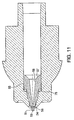
- FIGS. 9, 10, and 11 show an alternative embodiment of the injection assisting probe in which the retraction mechanism is a resilient O-ring 75, or other like material known to those skilled in the art.
- a coil spring can be used instead of the O-ring.
- the O-ring 75 it can also act as a sealing mechanism, and for this reason the O-ring is preferred.
- the interior of the probe is similar to the other embodiments, with a section 57 to accommodate the plunger and a tapered section 58 to funnel the medicament to the discharge channel 56 and out the discharge orifice 59 during operation.
- FIG. 10 illustrates the neutral condition, before expelling medicament
- FIG. 11 shows the extended condition during which medicament is expelled.
- this embodiment functions to extend the probe tip 51 beyond the nozzle opening 24 and tension the patient's skin during operation. Also, similar to embodiments previously described, this retractable probe also preferably has a ridge 55 around the proximal end to provide a surface which compresses the resilient material when the injector is triggered.
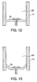
- FIGS. 12 and 13 Another embodiment of the present invention, shown in FIGS. 12 and 13, is a variation of the retraction means wherein a flexible membrane is utilized.
- FIG. 12 illustrates the neutral condition before expelling the medicament.
- a flexible membrane 70 spans between nozzle walls 71 which define the sides of the fluid chamber 26 for holding medicament. Similar to embodiments previously described, the distal end of the nozzle walls act to guard the probe by extending beyond the membrane the same distance the probe does.
- the probe is attached to the flexible membrane by any conventional means known to those skilled in the art. Preferably, the probe is integrally attached to the flexible membrane with an adhesive.
- FIG. 13 shows the probe in its extended position where the probe extends beyond the end of the walls such that the probe tensions the skin to allow injection of the medicine at reduced pressure.
- Other embodiments of the present invention relate to a nozzle assembly with a fixed probe. Both a one-piece and a two-piece nozzle assembly with a fixed probe can be used and are contemplated by this invention.
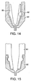
- FIGS. 14-17 show embodiments of the present invention with a two piece nozzle assembly with a fixed probe.
- the probe bearing section 80 can either be attached internally or externally from the nozzle member.
- FIGS. 14 and 15 show a preferable friction-fitting or snapping attaching means for both internal and external attachment of the probe bearing member respectively.
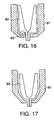
- FIG. 16 shows a preferable ultrasonic bonding means of attachment for the probe.
- the ultrasonic bonding features 83 can be placed at any location to attach the two pieces, preferably, the ultrasonic bonding features 83 are along the distal end at the interface between the probe member 80 and the nozzle member 81 to facilitate ease of manufacturing.
- FIG. 17 shows a preferable solvent bonding or adhesive bonding means of attachment.
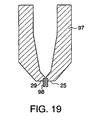
- FIG. 19 Another embodiment of a multi-piece nozzle assembly with a fixed probe is shown in FIG. 19.
- the nozzle assembly consists of a nozzle member 97 similar to a conventional nozzle member with the exception that the nozzle face 25 has a bore 29 coaxial with the center of the nozzle member 97 which is designed to receive a tubular insert 98 to create a fixed probe.
- the tubular insert 98 can be made of any suitable material, preferably the insert is stainless steel.
- the interior of the tubular insert 98 is cylindrical and functions as the discharge channel once it is inserted into the nozzle. Similar to previously described embodiments, the ratio of discharge channel length to orifice diameter is greater than 6.
- the tubular insert once inserted into the nozzle member, the tubular insert extends beyond the distal face of the nozzle. Preferably the tubular insert extends by 1.02 to 2.03 mm (0.04 to 0.08 inches) beyond the nozzle face.
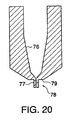
- FIG. 20 illustrates another embodiment of a fixed probe which has a one-piece nozzle assembly. Similar to embodiments described previously, the nozzle assembly has a funnel-like conical section 76 which tapers toward the discharge channel 77 at the distal end.
- the nozzle member of this embodiment is similar to the conventional nozzle member, with the exception that a probe 78 is integral with and extends outwardly from the nozzle distal face 79.
- FIG. 21 shows an alternative embodiment of the present invention which relates to nozzles having large length to diameter ratios, either with or without a probe attached at an end of the nozzle.
- diameter refers to the diameter of the discharge orifice 93 and length refers to the length of the discharge channel 92 or cylindrical section of the nozzle leading to the orifice.
- injectors have a length to diameter ratio of approximately 4/1 to 6/1.
- the length to diameter ratio of a nozzle according to the present invention is greater than 6/1.
- the ratio is at least 9/1 or even greater.
- a nozzle assembly with a large length to diameter ratio allows the use of a lower force energy mechanism without a reduction of pressure.
- a nozzle also has a long and gradual approach angle 91 leading to the discharge channel 92 of about 3 to 30 degrees.
- FIG. 18 shows a pressure-time curve for a conventional injector, curve A, which delivers a jet stream at steady state pressures around 27.5 MPa (4,000 p.s.i), as measured by the force of the stream of fluid divided by the cross-sectional area of the stream of fluid. Needleless injectors utilizing an injection-assisted probe, however, need only to achieve a lower steady state pressure as shown by curve B while maintaining the quality of the injection.
- experimentation has shown that the same percentage of successful injections can be achieved with needleless injectors having a probe of the present invention and 177.9 N (40 lb.) energy generating means as with conventional needleless injectors having 245 N (55 lb.) energy generating means. Furthermore, when injectors with the same energy generating means are compared with and without a probe of the present invention, the percentage of successful injections is increased with a probe. For instance, for an injector with a retracting probe, 100% of the injections in experimentation were successful, while only 68% of injections were successful without a probe. Injectors with a fixed probe were also advantageous, yielding 98% successful injections.
- the discharge channel 92 or cylindrical section leading to the discharge orifice 93 can be a metallic tube having the desired length to diameter ratio.
- a metallic tube in conjunction with a plastic nozzle assembly is preferred.
Abstract
Description
- The present invention is directed to a device for delivery of medicament, and in particular to a jet injector with a skin tensioning probe to reduce the pressure at which the jet injector must eject the medicament for proper delivery.
- A wide variety of needleless injectors are known in the art. Examples of such injectors include those described in U.S. Patent No. 5,599,302 issued to Lilley et al., U.S. Patent No. 5,062,830 to Dunlap, and U.S. Patent No. 4,790,824 to Morrow et al. In general, these and similar injectors administer medication as a fine, high velocity jet delivered under sufficient pressure to enable the jet to pass through the skin and enter the underlying tissues. These injectors typically have a nozzle assembly which has a barrel-like nozzle body having a medication holding chamber and an orifice through which a jet stream of medication is expelled from the chamber. Typically a plunger/piston actuated by an energy source, such as a coil spring, gas spring, or gas cartridge is used to expel the medicament.
- Since at least the 1980s, the use of needleless injectors has become more desirable due to concerns over the spread of AIDS, hepatitis and other viral diseases caused by the possibility of accidental needle "sticks" from the conventional syringe and needle. One of the advantages associated with jet injectors is the absence of a hypodermic needle which removes apprehensions of healthcare workers and are superior in eliminating accidental disease transmission. Furthermore, given the aversion to needles possessed by some, the absence of a needle provides a psychological benefit. Even devices that utilize conventional hypodermic needles have attempted to capitalize on this psychological benefit. For example, self injectors or auto-injectors like the ones disclosed in U.S. Patents No. 4,553,962, 4,378,015 have retractable needles which are hidden until activation. Upon activation, the needle extends from the bottom of the device and penetrates the user's skin to deliver medicament. As none of these devices involves delivery of the medicament using jet injection, the medicament delivery location is limited by the length of the needle.
- As the skin is a tissue composed of several layers and the injector is applied to the external surface of the outermost layer, the delivery pressure must be high enough to penetrate all layers of the skin. The layers of skin include, the epidermis, the outermost layer of skin, the dermis, and the subcutaneous region. The required delivery pressure is typically greater than approximately 27.5 MPa (4,000 p.s.i.), as measured by the force of the stream of fluid divided by the cross-sectional area of the stream of fluid.
- Although this pressure is readily achievable with most injectors, there are some circumstances in which delivery under a reduced pressure is desirable. For instance, certain medications which contain molecules with long protein chains can be sheared and rendered ineffective when expelled at high pressures. Reduced pressure delivery is particularly useful in intradermal applications such as vaccine, specifically DNA vaccines in which a high force energy mechanism could disrupt the molecular structure. See "Intradermal DNA Immunization by Using Jet-Injectors in Mice and Monkeys," Vaccine, 17:628-38, February 1999. Also, operation of the needleless injector at lower pressures can allow for a larger volume of medicament to be administered. Furthermore, the lower pressure could make manufacturing an injector device less expensive. The lower pressure would also reduce adverse stresses on the device and result in a corresponding increased useable device lifetime.
- US-A-5,769,138 relates to an adaptor which is connected to a container and a nozzle which is coupled with the adaptor to co-operate with the container.
- US-A-5,599,302 relates to a needleless injection system wherein a gas spring may be used in the needleless injector and an injection system includes a disposable, quick release coupling device for coupling a medication supply vial to the needleless injector.
- WO 96/36381 relates to an apparatus for the highpressure ejection of a liquid or a particle-containing liquid. The apparatus comprises a pressure chamber which accommodates the liquid, opens into an injection opening and is delimited by a working piston which can be displaced by a drive in the pressure chamber. The drive takes the form of an impact member which exerts a resilient impact on the working piston and can be accelerated such that it is driven until it strikes the working piston end remote from the pressure chamber. The impact member is not driven whilst the impact is transmitted. The volume of the pressure chamber is larger than the displacement volume of the liquid displaced by the working piston during its power stroke.
- US-A-3,507,276 relates to a hypodermic jet injector which has a jet orifice to which fluid is applied under pressure through a one-way valve from a cylinder. The cylinder is charged through a central opening and a one-way valve in piston from a canula carried by the piston. A single lever cocks the firing spring and then trips the latch upon further movement to fire the device by releasing a piston to provide the injection.
- According to the present invention there is provided an injection device according to claim 1.
- The present invention is drawn to a needleless injection system for injecting a medical product, and in particular, to a portable hand held device for injecting a medical product into a patient. The present invention is additionally drawn to an improved probe that can be used with a needleless injector.
- The neeedleless injector according to the present invention comprises a nozzle assembly having a fluid chamber for holding the medical product and an energy mechanism or energy means. The nozzle assembly has an orifice in fluid communication with the fluid chamber for allowing passage of the medical product in and out of the fluid chamber. The nozzle assembly is preferably removably connected and can be prefilled with a medical product if desired or can even be of a disposable type. A probe extends from the nozzle assembly to tension the skin and allow the jet to puncture the taut skin at a pressure that is substantially lower than the pressure normally needed to penetrate the skin.
- In one embodiment, the probe is retractably disposed within the nozzle assembly such that when the injector is fired, the probe is forced out of the end of the nozzle assembly. This stretches the skin, allowing the drug to enter the skin more easily. The diameter of the probe tip is smaller than the diameter of the opening at the distal end of the injector so that the probe tip can move within the opening. After the device has completed the injection, the probe is forced back into the nozzle assembly by a retractable means or mechanism. An O-ring or a spring typically provides the force necessary to retract the probe.
- Another aspect of the present invention includes the use of different retracting means. Either a membrane, O-ring seal and spring, or a coil spring may be used in any combination for this purpose.
- In another embodiment, the probe is rigidly disposed in the nozzle assembly in a fixed position and extends outwardly therefrom.
- In another embodiment, the probe is a metal cylinder inserted or molded in the injector to provide a large discharge channel length to orifice diameter ratio, i.e., in the range of at least about 6/1 to as high as 20/1 or even greater.
- In another embodiment, the rigid probe nozzle assembly is assembled from two separate pieces that can be joined either by being snapped together or otherwise interlocked, including by friction fitting, by being joined with an adhesive or by being ultrasonically bonded together.
- In yet another embodiment, the nozzle ratio of discharge channel length to orifice diameter is large, i.e., in the range of at least about 6/1 to as high as 20/1 or even greater, with a long and gradual approach angle of about 3 to 30 degrees.
- These and other features, aspects, and advantages of the present invention will become much more apparent from the following description and accompanying drawings in which:
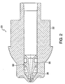
- FIG. 1 is a cross-sectional view of a needleless injector with a nozzle assembly of a first embodiment of the injection assisting probe therein.
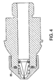
- FIG. 2 is a cross-sectional view of the needleless injector nozzle assembly of FIG. 1 with the injection assisting probe in its neutral condition.
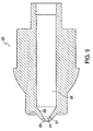
- FIG. 3 is a view similar to FIG. 2, but with the injection assisting probe in its extended condition.
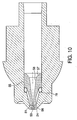
- FIG. 4 is a cross-sectional view of another embodiment of a nozzle assembly according to the present invention.
- FIG. 5 is an enlarged cross-sectional view of a conventional nozzle body with a section bored out of the inner opening.
- FIG. 6 is a perspective view of a conventional nozzle body.
- FIG. 7 is an enlarged cross-sectional view of the probe of the first embodiment.
- FIG. 8 is an enlarged perspective view of the probe of the first embodiment.
- FIG. 9 is an enlarged perspective view of an alternate embodiment of the probe.
- FIG. 10 is another embodiment of the nozzle assembly illustrated in FIG. 2, using a resilient O-ring as a retracting means and the probe of FIG. 9, showing the injection assisting probe in its neutral condition.
- FIG. 11 is a view similar to FIG. 10, but with the injection assisting probe in its extended condition.
- FIG. 12 is yet another embodiment of the nozzle assembly, using a flexible membrane as a retracting means, showing the injection assisting probe in its neutral condition.
- FIG. 13 is a view similar to FIG. 12, but with the injection assisting probe in its extended condition.
- FIGS. 14 and 15 illustrate a two-part nozzle assembly with a fixed probe wherein the probe member and nozzle member snap together.
- FIG. 16 illustrates a two-part nozzle assembly with a fixed probe wherein the probe member and nozzle member are ultrasonically welded together.
- FIG. 17 is a view similar to FIG. 16, but uses a solvent or adhesive bonding means.
- FIG. 18 shows an exemplary sample of a graph expressing a pressure-time curve between a conventional needleless injection device and an injection assisting probe device according to the present invention.
- FIG. 19 is a view of another embodiment of a multi-piece nozzle assembly with a fixed probe formed by a tubular insert.
- FIG. 20 illustrates another embodiment of a fixed probe which has a one-piece nozzle assembly.
- FIG. 21 illustrates yet another embodiment where the nozzle ratio of discharge channel length to orifice diameter is large with a long and gradual approach angle.
- For convenience, the same or equivalent elements of the invention of embodiments illustrated in the drawings have been identified with the same reference numerals. Further, in the description that follows, any reference to either orientation or direction is intended primarily for the convenience of description and is not intended in any way to limit the scope of the present invention thereto.
- As used in this application, the term distal shall designate the end or direction toward the front of the
needleless injection device 10. The term proximal shall designate the end or direction toward the rear of the injector. The term longitudinal designates an axis connecting thenozzle assembly 20 to theneedleless injection device 10, and the term transverse designates a direction substantially perpendicular to the longitudinal direction including arcs along the surface ofneedleless injection device 10, ornozzle assembly 20. - Referring to FIG. 1, the
needleless injection device 10 according to the present invention, comprises anozzle assembly 20, an energy generating means 40 for forcing medicament out of the nozzle assembly, and anactuating mechanism 90, and atrigger assembly 100 for activating and triggering theenergy mechanism 40. These components are operatively contained within ahousing 200 as shown. It should be noted that energy generating means 40 can be a coil spring, gas spring, gas propellant, or any other force generating means. - The
nozzle assembly 20 can be threadably connected to thehousing 200 or theactuating mechanism 90 such that it can be readily attached and detached. In this manner, theneedleless injection device 10 can be reused withvarious nozzle assemblies 20 that may contain different medications of different doses either together or at different times. For instance, thenozzle assembly 20 can be prefilled with medication and disposed of after each use. Further, a medication filling device such as a coupling device can be used to fill the fluid chamber with medication. - According to the first embodiment of the present invention, the
nozzle assembly 20 has an injection assisting probe movable within a conventional nozzle body. Thenozzle assembly 20 includes anozzle member 22 having anopening 24 at the distal end, preferably having a diameter of about 1.02-10.2 mm (0.04-0.4 inches), preferably of about 1.14 to 1.91 mm (0.045 to 0.075 inches) or any other suitable diameter that would allow for the introduction of an injection assisting probe therein. Thenozzle member 22 includes acylindrical fluid chamber 26 terminating at the distal end in a rightcircular cone 28. Aplunger 30 having a pressure wall contoured to thecone 28 is positioned to slide within thefluid chamber 26. Theplunger 30 can include sealing means such as one or more O-rings or the like (not shown) that are formed around its outer periphery to provide a seal, or the plunger itself can be a seal, as described in U.S. Patent No. 5,062,830. The plunger can also include additional sealing means at spaced intervals to provide a better seal. In the embodiments shown, theplunger 30 is connected to aram 32 which is connected to theenergy mechanism 40. Alternatively theram 32 can be integrally formed with an energy mechanism, if desired. - An
injection assisting probe 50, as seen best in FIGS. 7-8, is positioned coaxially and retractably within the distal end of thefluid chamber 26. Theinjection assisting probe 50 has aplunger receptor 57 at the proximal end which is configured to accommodate theplunger 30 as it slides within thefluid chamber 26. Although theplunger receptor 57 can be of any shape conforming to the exterior profile of the plunger, it is preferably conical. The probeinner wall 58 is contoured to narrow like a funnel to theprobe discharge channel 56. Theprobe discharge channel 56 extends to thedischarge orifice 59 at the distal end of the probe. Theprobe discharge orifice 59 has a diameter of 0.102 to 0.305 mm (0.004 to 0.012 inches). Preferably the diameter is 0.127 to 0.191 mm (0.005 to 0.0075 inches). Thedischarge channel 56 is cylindrical with a length to diameter ratio greater than 6. To provide a seal, the probe can include a sealing means such as an O-ring(s) 35 or the like, as shown in FIGS. 2 and 3, formed around its outer periphery and accommodated byslot 60 or the probe itself can be a seal. The probe preferably has aridge 55, the distal surface of which provides an annular area that can compress a spring or other like retractable mechanism when the needleless injection device is triggered. Alternatively, a washer can be used instead of theridge 55 to contain the O-ring 35 and compress the retracting mechanism during operation. - FIGS. 5 and 6 show the nozzle assembly prior to introduction of the injection assisting probe. The outer periphery of the probe can be of varied geometries such that it fits within the nozzle
member fluid chamber 26. Advantageously, the probe has aconical body section 54 which narrows gradually or tapers towards acylindrical body section 53 of smaller circumference. Preferably, ashoulder 52 is positioned to separate theprobe tip 51 from thecylindrical body section 53. Theprobe tip 51 is also cylindrical, but has a smaller circumference than thecylindrical body section 53 such that the probe tip can fit within and extend through thenozzle opening 24. Thecylindrical body section 53 of the probe has a circumference such that theshoulder section 52, existing at the transition between thecylindrical body section 53 and theprobe tip 51, prevents thecylindrical body section 53 of the probe from existing within theopening 24. - FIG. 2 illustrates the retractable
injection assisting probe 50 in its neutral position while FIG. 3 illustrates theprobe 50 in its extended position. In the extended position, theprobe tip 51 extends beyond the distal end of thenozzle face 25. Theshoulder 52 abuts the bored outinner section 27 of the nozzle opening to stop the probe from traveling further. The retracting mechanism, in this embodiment a spring, is compressed to provide a recoil force once the medicament is expelled. - FIG. 4 illustrates another aspect of the present invention where a nozzle assembly with a
nozzle member cap 85 attached on, for example by screws, to a modified nozzle member wherein a retractable probe is disposed. Although FIG. 4 shows the retractable means as a spring, there is no limitation as to the retractable means which can be used with such a screw on nozzle assembly. In this regard, a resilient O-ring, a flexible membrane, a gas spring, or any other retractable means known to those skilled in the art can also be used. - FIGS. 9, 10, and 11 show an alternative embodiment of the injection assisting probe in which the retraction mechanism is a resilient O-
ring 75, or other like material known to those skilled in the art. A coil spring can be used instead of the O-ring. When the O-ring 75 is used, it can also act as a sealing mechanism, and for this reason the O-ring is preferred. The interior of the probe is similar to the other embodiments, with asection 57 to accommodate the plunger and a taperedsection 58 to funnel the medicament to thedischarge channel 56 and out thedischarge orifice 59 during operation. FIG. 10 illustrates the neutral condition, before expelling medicament, and FIG. 11 shows the extended condition during which medicament is expelled. Similar to embodiments previously described, this embodiment functions to extend theprobe tip 51 beyond thenozzle opening 24 and tension the patient's skin during operation. Also, similar to embodiments previously described, this retractable probe also preferably has aridge 55 around the proximal end to provide a surface which compresses the resilient material when the injector is triggered. - Another embodiment of the present invention, shown in FIGS. 12 and 13, is a variation of the retraction means wherein a flexible membrane is utilized. FIG. 12 illustrates the neutral condition before expelling the medicament. A
flexible membrane 70 spans betweennozzle walls 71 which define the sides of thefluid chamber 26 for holding medicament. Similar to embodiments previously described, the distal end of the nozzle walls act to guard the probe by extending beyond the membrane the same distance the probe does. The probe is attached to the flexible membrane by any conventional means known to those skilled in the art. Preferably, the probe is integrally attached to the flexible membrane with an adhesive. FIG. 13 shows the probe in its extended position where the probe extends beyond the end of the walls such that the probe tensions the skin to allow injection of the medicine at reduced pressure. Other embodiments of the present invention relate to a nozzle assembly with a fixed probe. Both a one-piece and a two-piece nozzle assembly with a fixed probe can be used and are contemplated by this invention. - FIGS. 14-17 show embodiments of the present invention with a two piece nozzle assembly with a fixed probe. The
probe bearing section 80 can either be attached internally or externally from the nozzle member. Although, any conventional attaching means can be used, FIGS. 14 and 15 show a preferable friction-fitting or snapping attaching means for both internal and external attachment of the probe bearing member respectively. FIG. 16 shows a preferable ultrasonic bonding means of attachment for the probe. Although, the ultrasonic bonding features 83 can be placed at any location to attach the two pieces, preferably, the ultrasonic bonding features 83 are along the distal end at the interface between theprobe member 80 and thenozzle member 81 to facilitate ease of manufacturing. FIG. 17 shows a preferable solvent bonding or adhesive bonding means of attachment. - Another embodiment of a multi-piece nozzle assembly with a fixed probe is shown in FIG. 19. The nozzle assembly consists of a
nozzle member 97 similar to a conventional nozzle member with the exception that thenozzle face 25 has abore 29 coaxial with the center of thenozzle member 97 which is designed to receive atubular insert 98 to create a fixed probe. Although thetubular insert 98 can be made of any suitable material, preferably the insert is stainless steel. The interior of thetubular insert 98 is cylindrical and functions as the discharge channel once it is inserted into the nozzle. Similar to previously described embodiments, the ratio of discharge channel length to orifice diameter is greater than 6. Also similar to other embodiments of the present invention, once inserted into the nozzle member, the tubular insert extends beyond the distal face of the nozzle. Preferably the tubular insert extends by 1.02 to 2.03 mm (0.04 to 0.08 inches) beyond the nozzle face. - FIG. 20 illustrates another embodiment of a fixed probe which has a one-piece nozzle assembly. Similar to embodiments described previously, the nozzle assembly has a funnel-like
conical section 76 which tapers toward thedischarge channel 77 at the distal end. The nozzle member of this embodiment is similar to the conventional nozzle member, with the exception that aprobe 78 is integral with and extends outwardly from the nozzledistal face 79. - FIG. 21 shows an alternative embodiment of the present invention which relates to nozzles having large length to diameter ratios, either with or without a probe attached at an end of the nozzle. In FIG. 21 and throughout this application, diameter refers to the diameter of the
discharge orifice 93 and length refers to the length of thedischarge channel 92 or cylindrical section of the nozzle leading to the orifice. Currently, commercially available injectors have a length to diameter ratio of approximately 4/1 to 6/1. The length to diameter ratio of a nozzle according to the present invention is greater than 6/1. Preferably the ratio is at least 9/1 or even greater. As pressure is determined by force divided by cross-sectional area, using a nozzle assembly with a large length to diameter ratio allows the use of a lower force energy mechanism without a reduction of pressure. Preferably, such a nozzle also has a long andgradual approach angle 91 leading to thedischarge channel 92 of about 3 to 30 degrees. - A significant advantage of the injection-assisting probe is that it allows for a lower pressure to break the skin barrier and administer the medicament. In this regard, administering an injection using either a fixed or retractable probe requires less energy and force than conventional needless injector devices. FIG. 18 shows a pressure-time curve for a conventional injector, curve A, which delivers a jet stream at steady state pressures around 27.5 MPa (4,000 p.s.i), as measured by the force of the stream of fluid divided by the cross-sectional area of the stream of fluid. Needleless injectors utilizing an injection-assisted probe, however, need only to achieve a lower steady state pressure as shown by curve B while maintaining the quality of the injection. Specifically, experimentation has shown that the same percentage of successful injections can be achieved with needleless injectors having a probe of the present invention and 177.9 N (40 lb.) energy generating means as with conventional needleless injectors having 245 N (55 lb.) energy generating means. Furthermore, when injectors with the same energy generating means are compared with and without a probe of the present invention, the percentage of successful injections is increased with a probe. For instance, for an injector with a retracting probe, 100% of the injections in experimentation were successful, while only 68% of injections were successful without a probe. Injectors with a fixed probe were also advantageous, yielding 98% successful injections.
- Fabricating a nozzle assembly of two parts as described above facilitates manufacturing of a nozzle assembly with a large length to diameter ratio. Furthermore, the
discharge channel 92 or cylindrical section leading to thedischarge orifice 93 can be a metallic tube having the desired length to diameter ratio. As it is particularly problematic to fabricate nozzle assemblies with large length to diameter ratios out of plastic components, use of a metallic tube in conjunction with a plastic nozzle assembly is preferred. - While it is apparent that the illustrative embodiments of the invention herein disclosed fulfil the objectives stated above, it will be appreciated that numerous modifications and other embodiments may be devised by those skilled in the art. The scope of the invention is however defined by the appended claims.
Claims (15)
- An injection device (10) having a nozzle assembly (20), wherein said injection device (10) has a housing (200), a trigger assembly (100), and an energy generating source (40) operatively associated with the trigger assembly (100) so that movement of the trigger assembly (100) activates the energy source (40) to move a plunger (30) in a first direction, said nozzle assembly (20) comprising:a fluid chamber (26) for holding fluid; anda nozzle discharge channel (56) in fluid communication with an end of the fluid chamber (26) and having an orifice (59) through which fluid is expelled when the plunger (30) is moved in the first direction;wherein the energy source (40) and discharge channel (56) are configured to expel fluid through the orifice (59) to jet inject the fluid, and the discharge channel (56) has a discharge channel length and the orifice (59) has an orifice diameter; and
wherein the diameter along the discharge channel length and the diameter of the orifice (59) are the same and the ratio of discharge channel length to orifice diameter is greater than 6. - The injection device (10) of claim 1, wherein the orifice diameter is between 0.102 to 0.305mm (0.004 to 0.012 inches).
- The injection device (10) of claim 1, wherein the discharge channel length is at least 0.610mm (0.024 inches).
- The injection device of claim 1, wherein the discharge channel length to orifice diameter is greater than 9.
- The injection device (10) of claim 1, further comprising a retractable injection-assisting probe (50) at a distal end of the injection device (10), wherein the nozzle assembly (20) defines an opening (24) for slidingly receiving at least a portion of the probe (50), the injection-assisting probe (50) comprising:a probe tip (51) located at a distal end of the probe (50) with at least a portion configured and dimensioned to slide within the nozzle assembly opening (24);the discharge channel (56) which is defined within the probe tip (51);a body portion extending towards the discharge channel (56);a plunger receptor (57) configured and dimensioned to receive at least a portion of the plunger (30);a retraction element operatively associated with the nozzle assembly (20), wherein the probe (50) is located within the nozzle assembly (20) in a retracted position prior to activation of the energy source (40);movement of the plunger (30) in the first direction upon activation of the energy source (40) results in at least a portion of the probe tip (51) extending from the nozzle assembly opening (24); andthe retraction element is configured to return the probe tip (51) to the retracted position after activation of the energy source (40).
- The injection device (10) according to claim 5, wherein the retraction element is one of a resilient O-ring, a spring, or a flexible membrane.
- The injection device (10) according to claim 5, wherein the probe body has an exterior surface that includes a ridge (55) for accommodating the retraction element.
- The injection device (10) according to claim 5, further comprising a shoulder (52) disposed between the probe tip (51) and the probe body for limiting the portion of the probe tip (51) that extends from the nozzle assembly opening (24).
- The injection device (10) according to claim 5, wherein the body portion has a funnel-shaped interior which tapers toward the discharge channel (56).
- The injection device (10) of claim 1, further comprising a fixed injection-assisting probe (80) at a distal end of the injection device (10) and configured to tension to tensioning an injection site and comprising:a body fixed to a distal end of the nozzle assembly (20); andthe discharge channel (56), which extends through the probe body,wherein tensioning the injection site reduces the pressure sufficient to jet inject the fluid.
- The injection device (10) according to claim 10, wherein a metal tube is located in the probe body and forms the discharge channel (56).
- The injection device (10) according to claim 11, wherein Zthe metal tube is made of stainless steel.
- The injection device (10) according to claim 10, wherein the nozzle assembly (20) comprises two sections that are joined by ultrasonic bonding means, screwing means, friction fitting means, adhesive bonding means, or snapping attaching means.
- The injection device (10) of claim 1, wherein the energy source (40) and discharge channel (56) are capable of generating steady state pressures at around 27.5 MPa (4,000 p.s.i.).
- The injection device (10) of claim 1, where the energy source (40) produces 177.9N (40 lbs.) of force.
Applications Claiming Priority (3)
| Application Number | Priority Date | Filing Date | Title |
|---|---|---|---|
| US9416798P | 1998-07-27 | 1998-07-27 | |
| US94167P | 1998-07-27 | ||
| PCT/US1999/016863 WO2000006228A1 (en) | 1998-07-27 | 1999-07-26 | Injection-assisting probe for medical injector assembly |
Publications (3)
| Publication Number | Publication Date |
|---|---|
| EP1102606A1 EP1102606A1 (en) | 2001-05-30 |
| EP1102606A4 EP1102606A4 (en) | 2003-01-02 |
| EP1102606B1 true EP1102606B1 (en) | 2006-10-11 |
Family
ID=22243557
Family Applications (1)
| Application Number | Title | Priority Date | Filing Date |
|---|---|---|---|
| EP99937475A Expired - Lifetime EP1102606B1 (en) | 1998-07-27 | 1999-07-26 | Injection-assisting probe for medical injector assembly |
Country Status (10)
| Country | Link |
|---|---|
| US (2) | US6309371B1 (en) |
| EP (1) | EP1102606B1 (en) |
| JP (2) | JP4294868B2 (en) |
| KR (1) | KR100622160B1 (en) |
| CN (2) | CN1202874C (en) |
| AT (1) | ATE342079T1 (en) |
| AU (1) | AU5230299A (en) |
| DE (1) | DE69933569T2 (en) |
| ES (1) | ES2276524T3 (en) |
| WO (1) | WO2000006228A1 (en) |
Families Citing this family (65)
| Publication number | Priority date | Publication date | Assignee | Title |
|---|---|---|---|---|
| US6474369B2 (en) | 1995-05-26 | 2002-11-05 | Penjet Corporation | Apparatus and method for delivering a lyophilized active with a needle-less injector |
| EP1102606B1 (en) * | 1998-07-27 | 2006-10-11 | Antares Pharma, Inc. | Injection-assisting probe for medical injector assembly |
| US7060048B1 (en) * | 1999-04-16 | 2006-06-13 | Powerject Research Limited | Needleless syringe |
| US6802826B1 (en) * | 1999-10-11 | 2004-10-12 | Felton International, Inc. | Universal anti-infectious protector for needleless injectors |
| US7074210B2 (en) * | 1999-10-11 | 2006-07-11 | Felton International, Inc. | Universal protector cap with auto-disable features for needle-free injectors |
| US6673035B1 (en) * | 1999-10-22 | 2004-01-06 | Antares Pharma, Inc. | Medical injector and medicament loading system for use therewith |
| US6406456B1 (en) | 2000-06-08 | 2002-06-18 | Avant Drug Delivery Systems, Inc. | Jet injector |
| DE10029325A1 (en) * | 2000-06-20 | 2002-01-03 | Peter Lell | Needle-free injection device with pyrotechnic drive |
| US6500239B2 (en) | 2001-03-14 | 2002-12-31 | Penjet Corporation | System and method for removing dissolved gas from a solution |
| US6613010B2 (en) * | 2001-04-13 | 2003-09-02 | Penjet Corporation | Modular gas-pressured needle-less injector |
| US6755220B2 (en) | 2001-04-27 | 2004-06-29 | Penjet Corporation | Method and apparatus for filling or refilling a needle-less injector |
| FR2830455B1 (en) * | 2001-10-09 | 2004-06-25 | Saphir Medical | CATHETER WITH RETRACTABLE PERFORATING OR STITCHING TOOL |
| EP1441789B1 (en) * | 2001-10-12 | 2009-07-01 | Felton International, Inc. | Universal protector cap with auto-disable features for needle-free injectors |
| US6824526B2 (en) | 2001-10-22 | 2004-11-30 | Penjet Corporation | Engine and diffuser for use with a needle-less injector |
| GB0125506D0 (en) * | 2001-10-24 | 2001-12-12 | Weston Medical Ltd | Needle free injection method and apparatus |
| JP3993169B2 (en) | 2002-02-11 | 2007-10-17 | アンタレス・ファーマ・インコーポレーテッド | Intradermal syringe |
| CN100509069C (en) * | 2003-08-12 | 2009-07-08 | 贝克顿·迪金森公司 | Patch-like infusion device |
| AU2004298717A1 (en) * | 2003-12-18 | 2005-06-30 | Novo Nordisk A/S | Nozzle device with skin stretching means |
| EP1796765B1 (en) * | 2004-08-13 | 2017-11-01 | Becton, Dickinson and Company | Retractable needle syringe assembly |
| BRPI0515759B8 (en) | 2004-12-01 | 2021-06-22 | Acushot Inc | needleless injection device and kit for using it |
| CN101132820B (en) | 2005-01-24 | 2010-05-19 | 安塔雷斯制药公司 | Prefilled needle assisted jet injector |
| US20070055200A1 (en) | 2005-08-10 | 2007-03-08 | Gilbert Scott J | Needle-free jet injection drug delivery device |
| US9144648B2 (en) * | 2006-05-03 | 2015-09-29 | Antares Pharma, Inc. | Injector with adjustable dosing |
| WO2007131013A1 (en) | 2006-05-03 | 2007-11-15 | Antares Pharma, Inc. | Two-stage reconstituting injector |
| ES2548447T3 (en) | 2008-03-10 | 2015-10-16 | Antares Pharma, Inc. | Injector safety device |
| US8376993B2 (en) | 2008-08-05 | 2013-02-19 | Antares Pharma, Inc. | Multiple dosage injector |
| GB2462669B (en) * | 2008-08-11 | 2012-12-05 | Managed Technologies Ltd | Needle-free injection apparatus and method |
| AU2009322967B2 (en) * | 2008-12-05 | 2015-06-11 | Ams Research Corporation | Devices, systems and methods for delivering fluid to tissue |
| AU2010226442A1 (en) | 2009-03-20 | 2011-10-13 | Antares Pharma, Inc. | Hazardous agent injection system |
| DE102009002826A1 (en) * | 2009-05-05 | 2010-11-11 | Beiersdorf Ag | Needle-free injection system for delivering cosmetic active ingredients in dermis or epidermis for restructuring connective tissue, improving skin aging, reducing scar tissue and modulating sweating, comprises injector and drug formulations |
| AU2010278894B2 (en) | 2009-07-30 | 2014-01-30 | Tandem Diabetes Care, Inc. | Infusion pump system with disposable cartridge having pressure venting and pressure feedback |
| US9550030B2 (en) | 2010-07-22 | 2017-01-24 | Becton, Dickinson And Company | Dual chamber syringe with retractable needle |
| US8721599B2 (en) | 2010-07-22 | 2014-05-13 | Becton, Dickinson And Company | Dual chamber passive retraction needle syringe |
| US8556854B2 (en) | 2010-07-22 | 2013-10-15 | Becton, Dickinson And Company | Dual chamber syringe with retractable needle |
| US8556855B2 (en) | 2010-07-22 | 2013-10-15 | Becton, Dickinson And Company | Dual chamber syringe with retractable needle |
| JP5608498B2 (en) * | 2010-09-24 | 2014-10-15 | 株式会社ダイセル | Syringe |
| JP5628698B2 (en) * | 2011-02-04 | 2014-11-19 | 株式会社ダイセル | Needleless syringe nozzle and needleless syringe |
| US8496619B2 (en) | 2011-07-15 | 2013-07-30 | Antares Pharma, Inc. | Injection device with cammed ram assembly |
| US9220660B2 (en) | 2011-07-15 | 2015-12-29 | Antares Pharma, Inc. | Liquid-transfer adapter beveled spike |
| DE102011119055B4 (en) * | 2011-11-16 | 2013-08-14 | Lts Lohmann Therapie-Systeme Ag | Cylinder-piston unit with adhesive disk II |
| DE102011119058B3 (en) * | 2011-11-16 | 2012-11-08 | Lts Lohmann Therapie-Systeme Ag | Cylinder-piston unit with adhesive disk I |
| EP2822618B1 (en) | 2012-03-06 | 2024-01-10 | Antares Pharma, Inc. | Prefilled syringe with breakaway force feature |
| EP2833944A4 (en) | 2012-04-06 | 2016-05-25 | Antares Pharma Inc | Needle assisted jet injection administration of testosterone compositions |
| US9364610B2 (en) | 2012-05-07 | 2016-06-14 | Antares Pharma, Inc. | Injection device with cammed ram assembly |
| JP5973228B2 (en) | 2012-05-11 | 2016-08-23 | 株式会社ダイセル | Syringe |
| US9180242B2 (en) | 2012-05-17 | 2015-11-10 | Tandem Diabetes Care, Inc. | Methods and devices for multiple fluid transfer |
| JP6116874B2 (en) * | 2012-11-27 | 2017-04-19 | 株式会社ダイセル | Syringe |
| EP2953667B1 (en) | 2013-02-11 | 2019-10-23 | Antares Pharma, Inc. | Needle assisted jet injection device having reduced trigger force |
| WO2014164786A1 (en) | 2013-03-11 | 2014-10-09 | Madsen Patrick | Dosage injector with pinion system |
| WO2014165136A1 (en) | 2013-03-12 | 2014-10-09 | Antares Pharma, Inc. | Constant volume prefilled syringes and kits thereof |
| US9173998B2 (en) | 2013-03-14 | 2015-11-03 | Tandem Diabetes Care, Inc. | System and method for detecting occlusions in an infusion pump |
| CN103816589A (en) * | 2014-03-03 | 2014-05-28 | 山东中保康医疗器具有限公司 | Large-volume multi-head needleless injector |
| JP2016049246A (en) | 2014-08-29 | 2016-04-11 | 株式会社ダイセル | Needleless injector |
| ES2893152T3 (en) | 2015-01-21 | 2022-02-08 | Antares Pharma Inc | Variable dosage injection device |
| US10492141B2 (en) | 2015-11-17 | 2019-11-26 | Tandem Diabetes Care, Inc. | Methods for reduction of battery usage in ambulatory infusion pumps |
| SG11201805374RA (en) * | 2015-12-28 | 2018-07-30 | Inovio Pharmaceuticals Inc | Intradermal jet injection electroporation device |
| US10500351B2 (en) | 2016-02-12 | 2019-12-10 | Shawn Michael Michels | Aid for subcutaneous tissue injection and process of effecting the injection with the aid |
| US10625021B2 (en) * | 2016-03-09 | 2020-04-21 | Portal Instruments, Inc. | Apparatus for reinforcing syringe cartridge |
| JP6254644B2 (en) * | 2016-07-14 | 2017-12-27 | 株式会社ダイセル | Syringe |
| WO2019124852A1 (en) | 2017-12-19 | 2019-06-27 | 조민수 | Needleless injection syringe |
| WO2020138476A1 (en) * | 2018-12-27 | 2020-07-02 | 株式会社ダイセル | Needleless syringe |
| EP3912658A4 (en) * | 2019-01-16 | 2022-10-19 | Daicel Corporation | Needleless syringe |
| CN111110958B (en) * | 2020-02-06 | 2021-08-17 | 唐文珍 | Syringe used in medical field |
| KR102357177B1 (en) * | 2020-07-01 | 2022-01-28 | 주식회사 메디젯 | Drug delivery apparatus |
| CN112008235B (en) * | 2020-07-20 | 2021-07-13 | 奔腾激光(温州)有限公司 | Gas-saving nozzle for high-power laser cutting |
Family Cites Families (66)
| Publication number | Priority date | Publication date | Assignee | Title |
|---|---|---|---|---|
| US2322244A (en) | 1940-03-18 | 1943-06-22 | Marshall L Lockhart | Hypodermic injector |
| US2380534A (en) | 1941-04-26 | 1945-07-31 | Marshall L Lockhart | Hypodermic injector |
| US2398544A (en) | 1945-01-06 | 1946-04-16 | Marshall L Lockhart | Hypodermic injector |
| US2605763A (en) | 1948-01-31 | 1952-08-05 | Becton Dickinson Co | Injection device |
| US2547099A (en) | 1948-03-11 | 1951-04-03 | Becton Dickinson Co | Injection device and ampoule |
| US2754818A (en) | 1950-06-24 | 1956-07-17 | Scherer Corp R P | Hypo jet injector |
| US2671347A (en) | 1950-06-24 | 1954-03-09 | Scherer Corp R P | Latch structure |
| US2675802A (en) | 1950-12-19 | 1954-04-20 | Jr George N Hein | Injection device |
| US2650591A (en) | 1951-03-10 | 1953-09-01 | Ideal Roller And Mfg Company | Device for making injections |
| US2667874A (en) | 1951-07-09 | 1954-02-02 | Becton Dickinson Co | Medicament cartridge assembly |
| US2667871A (en) | 1951-11-20 | 1954-02-02 | Jr George N Hein | Hypodermic injection apparatus |
| US2762369A (en) | 1954-09-07 | 1956-09-11 | Scherer Corp R P | Hypodermic injector with adjustable impact plunger |
| US2896977A (en) | 1954-12-30 | 1959-07-28 | Hansen Mfg Co | Bayonet lock coupling |
| NL106573C (en) | 1957-05-31 | |||
| US3057349A (en) | 1959-12-14 | 1962-10-09 | Ismach Aaron | Multi-dose jet injection device |
| US3138157A (en) | 1961-05-12 | 1964-06-23 | Z & W Mfg Corp | Inoculant injector instrument |
| US3330276A (en) | 1963-10-07 | 1967-07-11 | Scherer Corp R P | Hypodermic jet injector |
| US3292622A (en) | 1964-09-21 | 1966-12-20 | Oscar H Banker | Power operated inoculator |
| US3515130A (en) | 1966-09-21 | 1970-06-02 | Yuryo Kikakuhin Kenkyusho Kk | Jet-injection hypodermic device |
| US3507276A (en) | 1968-08-28 | 1970-04-21 | Murray B Burgess | Jet injector |
| US3688765A (en) | 1969-10-03 | 1972-09-05 | Jack S Gasaway | Hypodermic injection device |
| US4089334A (en) | 1976-10-07 | 1978-05-16 | Schwebel Paul R | Pyrotechnically powered needleless injector |
| BR7806153A (en) | 1978-09-19 | 1980-04-01 | Halen Elliot Brasil Ind Com Eq | HYPODERMIC PRESSURE INJECTOR FOR INTERMITTENT VACCINATION |
| US4258713A (en) | 1979-07-23 | 1981-03-31 | Wardlaw Stephen C | Automatic disposable hypodermic syringe |
| US4296747A (en) | 1980-02-11 | 1981-10-27 | Ims Limited | Cath-a-jet |
| US4373559A (en) | 1980-12-04 | 1983-02-15 | Abbott Laboratories | Apparatus for pressurizing an additive transfer device |
| US4378015A (en) | 1981-12-21 | 1983-03-29 | Wardlaw Stephen C | Automatic injecting syringe |
| CA1178503A (en) | 1982-05-27 | 1984-11-27 | Health-Mor Personal Care Corporation | Needleless hypodermic injector |
| FR2539302B1 (en) | 1983-01-17 | 1986-03-14 | Brunet Jean Louis | SYRINGE FOR MEDICAL USE |
| EP0119286B1 (en) | 1983-03-18 | 1987-12-23 | Internationales Forschungsinstitut für Reproduktionsmedizin und -biologie | Pressure-powered injection pistol |
| US4588403A (en) | 1984-06-01 | 1986-05-13 | American Hospital Supply Corporation | Vented syringe adapter assembly |
| US4596556A (en) | 1985-03-25 | 1986-06-24 | Bioject, Inc. | Hypodermic injection apparatus |
| US4675020A (en) | 1985-10-09 | 1987-06-23 | Kendall Mcgaw Laboratories, Inc. | Connector |
| US4719825A (en) | 1986-03-24 | 1988-01-19 | Lahaye Peter G | Metering needle assembly |
| DE3638984C3 (en) | 1986-11-14 | 1993-11-18 | Haselmeier Wilhelm Fa | Injection device |
| HU195428B (en) | 1987-02-17 | 1988-05-30 | Fegyver Es Gazkeszuelekgyar | Needleless vaccinating instrument of adjustable injection depth operable by hand-power |
| US4790824A (en) * | 1987-06-19 | 1988-12-13 | Bioject, Inc. | Non-invasive hypodermic injection device |
| US4940460A (en) | 1987-06-19 | 1990-07-10 | Bioject, Inc. | Patient-fillable and non-invasive hypodermic injection device assembly |
| IL86799A (en) | 1987-07-02 | 1993-03-15 | Kabi Pharmacia Ab | Method and device for injection |
| CH675078A5 (en) | 1988-01-22 | 1990-08-31 | Nosta Ag | |
| US4913699A (en) | 1988-03-14 | 1990-04-03 | Parsons James S | Disposable needleless injection system |
| US5052725A (en) | 1989-03-13 | 1991-10-01 | Colder Products Company | Two piece molded female coupling |
| US5312335A (en) | 1989-11-09 | 1994-05-17 | Bioject Inc. | Needleless hypodermic injection device |
| US5064413A (en) | 1989-11-09 | 1991-11-12 | Bioject, Inc. | Needleless hypodermic injection device |
| US4989905A (en) | 1990-02-05 | 1991-02-05 | Lamson & Sessions Co. | Fitting for corrugated tubing |
| GB9007113D0 (en) | 1990-03-29 | 1990-05-30 | Sams Bernard | Dispensing device |
| US5062830A (en) | 1990-04-04 | 1991-11-05 | Derata Corporation | Dry disposable nozzle assembly for medical jet injector |
| FR2674747B1 (en) | 1991-04-05 | 1993-07-30 | Step Soc Tech Pulverisation | DEVICE FOR DISPENSING DROPS OF SMALL VOLUME, PARTICULARLY FOR OPHTHALMOLOGICAL CARE. |
| GB9118204D0 (en) | 1991-08-23 | 1991-10-09 | Weston Terence E | Needle-less injector |
| US5221348A (en) * | 1991-11-26 | 1993-06-22 | Masano Thomas C | High pressure glue injector |
| US5360413A (en) | 1991-12-06 | 1994-11-01 | Filtertek, Inc. | Needleless access device |
| US5383851A (en) | 1992-07-24 | 1995-01-24 | Bioject Inc. | Needleless hypodermic injection device |
| US5569189A (en) | 1992-09-28 | 1996-10-29 | Equidyne Systems, Inc. | hypodermic jet injector |
| US5334144A (en) * | 1992-10-30 | 1994-08-02 | Becton, Dickinson And Company | Single use disposable needleless injector |
| US5373684A (en) | 1992-12-14 | 1994-12-20 | Mallinckrodt Medical, Inc. | Process and apparatus used in producing prefilled, sterile delivery devices |
| US5476449A (en) | 1992-12-28 | 1995-12-19 | Richmond; Frank M. | Needleless multi-liquid medicament delivery system with membranes |
| US5891086A (en) | 1993-07-31 | 1999-04-06 | Weston Medical Limited | Needle-less injector |
| US5536249A (en) | 1994-03-09 | 1996-07-16 | Visionary Medical Products, Inc. | Pen-type injector with a microprocessor and blood characteristic monitor |
| US5454805A (en) | 1994-03-14 | 1995-10-03 | Brony; Seth K. | Medicine vial link for needleless syringes |
| GB9425642D0 (en) | 1994-12-20 | 1995-02-22 | Weston Medical Ltd | Filling device |
| US5599302A (en) | 1995-01-09 | 1997-02-04 | Medi-Ject Corporation | Medical injection system and method, gas spring thereof and launching device using gas spring |
| WO1996024398A1 (en) | 1995-02-06 | 1996-08-15 | Weston Medical Limited | Needle-less injector |
| GB9504878D0 (en) | 1995-03-10 | 1995-04-26 | Weston Medical Ltd | Viscously coupled actuator |
| DE29507987U1 (en) * | 1995-05-15 | 1996-09-19 | Ferton Holding | Ejection device for high pressure ejection of a liquid |
| US5769138A (en) * | 1996-04-01 | 1998-06-23 | Medi-Ject Corporation | Nozzle and adapter for loading medicament into an injector |
| EP1102606B1 (en) * | 1998-07-27 | 2006-10-11 | Antares Pharma, Inc. | Injection-assisting probe for medical injector assembly |
-
1999
- 1999-07-26 EP EP99937475A patent/EP1102606B1/en not_active Expired - Lifetime
- 1999-07-26 DE DE69933569T patent/DE69933569T2/en not_active Expired - Fee Related
- 1999-07-26 CN CNB998113018A patent/CN1202874C/en not_active Expired - Fee Related
- 1999-07-26 JP JP2000562078A patent/JP4294868B2/en not_active Expired - Lifetime
- 1999-07-26 US US09/359,790 patent/US6309371B1/en not_active Expired - Lifetime
- 1999-07-26 CN CNA2005100040442A patent/CN1651103A/en active Pending
- 1999-07-26 AU AU52302/99A patent/AU5230299A/en not_active Abandoned
- 1999-07-26 ES ES99937475T patent/ES2276524T3/en not_active Expired - Lifetime
- 1999-07-26 WO PCT/US1999/016863 patent/WO2000006228A1/en active IP Right Grant
- 1999-07-26 AT AT99937475T patent/ATE342079T1/en not_active IP Right Cessation
- 1999-07-26 KR KR1020017001125A patent/KR100622160B1/en not_active IP Right Cessation
-
2001
- 2001-10-29 US US10/034,926 patent/US7108675B2/en not_active Expired - Fee Related
-
2008
- 2008-12-17 JP JP2008321302A patent/JP2009056339A/en active Pending
Also Published As
| Publication number | Publication date |
|---|---|
| EP1102606A1 (en) | 2001-05-30 |
| DE69933569T2 (en) | 2007-06-28 |
| AU5230299A (en) | 2000-02-21 |
| WO2000006228A1 (en) | 2000-02-10 |
| ES2276524T3 (en) | 2007-06-16 |
| KR100622160B1 (en) | 2006-09-07 |
| ATE342079T1 (en) | 2006-11-15 |
| CN1319024A (en) | 2001-10-24 |
| JP2009056339A (en) | 2009-03-19 |
| EP1102606A4 (en) | 2003-01-02 |
| CN1202874C (en) | 2005-05-25 |
| CN1651103A (en) | 2005-08-10 |
| JP4294868B2 (en) | 2009-07-15 |
| US20020058907A1 (en) | 2002-05-16 |
| JP2002521148A (en) | 2002-07-16 |
| US6309371B1 (en) | 2001-10-30 |
| KR20010074767A (en) | 2001-08-09 |
| US7108675B2 (en) | 2006-09-19 |
| DE69933569D1 (en) | 2006-11-23 |
Similar Documents
| Publication | Publication Date | Title |
|---|---|---|
| EP1102606B1 (en) | Injection-assisting probe for medical injector assembly | |
| US6428528B2 (en) | Needle assisted jet injector | |
| US10646662B2 (en) | Intradermal injector | |
| US6391003B1 (en) | Locking mechanism for a jet injector | |
| US6123684A (en) | Loading mechanism for medical injector assembly |
Legal Events
| Date | Code | Title | Description |
|---|---|---|---|
| PUAI | Public reference made under article 153(3) epc to a published international application that has entered the european phase |
Free format text: ORIGINAL CODE: 0009012 |
|
| 17P | Request for examination filed |
Effective date: 20010213 |
|
| AK | Designated contracting states |
Kind code of ref document: A1 Designated state(s): AT BE CH CY DE DK ES FI FR GB GR IE IT LI LU MC NL PT SE |
|
| AX | Request for extension of the european patent |
Free format text: AL;LT;LV;MK;RO;SI |
|
| RAP1 | Party data changed (applicant data changed or rights of an application transferred) |
Owner name: BECTON, DICKINSON AND COMPANY Owner name: ANTARES PHARMA, INC. |
|
| RIC1 | Information provided on ipc code assigned before grant |
Free format text: 7A 61M 5/30 A, 7B 65B 1/04 B |
|
| A4 | Supplementary search report drawn up and despatched |
Effective date: 20021108 |
|
| AK | Designated contracting states |
Kind code of ref document: A4 Designated state(s): AT BE CH CY DE DK ES FI FR GB GR IE IT LI LU MC NL PT SE |
|
| 17Q | First examination report despatched |
Effective date: 20030520 |
|
| GRAP | Despatch of communication of intention to grant a patent |
Free format text: ORIGINAL CODE: EPIDOSNIGR1 |
|
| DAX | Request for extension of the european patent (deleted) | ||
| GRAS | Grant fee paid |
Free format text: ORIGINAL CODE: EPIDOSNIGR3 |
|
| GRAA | (expected) grant |
Free format text: ORIGINAL CODE: 0009210 |
|
| AK | Designated contracting states |
Kind code of ref document: B1 Designated state(s): AT BE CH CY DE DK ES FI FR GB GR IE IT LI LU MC NL PT SE |
|
| PG25 | Lapsed in a contracting state [announced via postgrant information from national office to epo] |
Ref country code: NL Free format text: LAPSE BECAUSE OF FAILURE TO SUBMIT A TRANSLATION OF THE DESCRIPTION OR TO PAY THE FEE WITHIN THE PRESCRIBED TIME-LIMIT Effective date: 20061011 Ref country code: LI Free format text: LAPSE BECAUSE OF FAILURE TO SUBMIT A TRANSLATION OF THE DESCRIPTION OR TO PAY THE FEE WITHIN THE PRESCRIBED TIME-LIMIT Effective date: 20061011 Ref country code: IT Free format text: LAPSE BECAUSE OF FAILURE TO SUBMIT A TRANSLATION OF THE DESCRIPTION OR TO PAY THE FEE WITHIN THE PRESCRIBED TIME-LIMIT;WARNING: LAPSES OF ITALIAN PATENTS WITH EFFECTIVE DATE BEFORE 2007 MAY HAVE OCCURRED AT ANY TIME BEFORE 2007. THE CORRECT EFFECTIVE DATE MAY BE DIFFERENT FROM THE ONE RECORDED. Effective date: 20061011 Ref country code: FI Free format text: LAPSE BECAUSE OF FAILURE TO SUBMIT A TRANSLATION OF THE DESCRIPTION OR TO PAY THE FEE WITHIN THE PRESCRIBED TIME-LIMIT Effective date: 20061011 Ref country code: CH Free format text: LAPSE BECAUSE OF FAILURE TO SUBMIT A TRANSLATION OF THE DESCRIPTION OR TO PAY THE FEE WITHIN THE PRESCRIBED TIME-LIMIT Effective date: 20061011 Ref country code: BE Free format text: LAPSE BECAUSE OF FAILURE TO SUBMIT A TRANSLATION OF THE DESCRIPTION OR TO PAY THE FEE WITHIN THE PRESCRIBED TIME-LIMIT Effective date: 20061011 Ref country code: AT Free format text: LAPSE BECAUSE OF FAILURE TO SUBMIT A TRANSLATION OF THE DESCRIPTION OR TO PAY THE FEE WITHIN THE PRESCRIBED TIME-LIMIT Effective date: 20061011 |
|
| REG | Reference to a national code |
Ref country code: GB Ref legal event code: FG4D |
|
| REG | Reference to a national code |
Ref country code: CH Ref legal event code: EP |
|
| REG | Reference to a national code |
Ref country code: IE Ref legal event code: FG4D |
|
| REF | Corresponds to: |
Ref document number: 69933569 Country of ref document: DE Date of ref document: 20061123 Kind code of ref document: P |
|
| PG25 | Lapsed in a contracting state [announced via postgrant information from national office to epo] |
Ref country code: SE Free format text: LAPSE BECAUSE OF FAILURE TO SUBMIT A TRANSLATION OF THE DESCRIPTION OR TO PAY THE FEE WITHIN THE PRESCRIBED TIME-LIMIT Effective date: 20070111 Ref country code: DK Free format text: LAPSE BECAUSE OF FAILURE TO SUBMIT A TRANSLATION OF THE DESCRIPTION OR TO PAY THE FEE WITHIN THE PRESCRIBED TIME-LIMIT Effective date: 20070111 |
|
| PG25 | Lapsed in a contracting state [announced via postgrant information from national office to epo] |
Ref country code: PT Free format text: LAPSE BECAUSE OF FAILURE TO SUBMIT A TRANSLATION OF THE DESCRIPTION OR TO PAY THE FEE WITHIN THE PRESCRIBED TIME-LIMIT Effective date: 20070319 |
|
| NLV1 | Nl: lapsed or annulled due to failure to fulfill the requirements of art. 29p and 29m of the patents act | ||
| REG | Reference to a national code |
Ref country code: CH Ref legal event code: PL |
|
| ET | Fr: translation filed | ||
| REG | Reference to a national code |
Ref country code: ES Ref legal event code: FG2A Ref document number: 2276524 Country of ref document: ES Kind code of ref document: T3 |
|
| PLBE | No opposition filed within time limit |
Free format text: ORIGINAL CODE: 0009261 |
|
| STAA | Information on the status of an ep patent application or granted ep patent |
Free format text: STATUS: NO OPPOSITION FILED WITHIN TIME LIMIT |
|
| 26N | No opposition filed |
Effective date: 20070712 |
|
| PG25 | Lapsed in a contracting state [announced via postgrant information from national office to epo] |
Ref country code: MC Free format text: LAPSE BECAUSE OF NON-PAYMENT OF DUE FEES Effective date: 20070731 Ref country code: GR Free format text: LAPSE BECAUSE OF FAILURE TO SUBMIT A TRANSLATION OF THE DESCRIPTION OR TO PAY THE FEE WITHIN THE PRESCRIBED TIME-LIMIT Effective date: 20070112 |
|
| PG25 | Lapsed in a contracting state [announced via postgrant information from national office to epo] |
Ref country code: IE Free format text: LAPSE BECAUSE OF NON-PAYMENT OF DUE FEES Effective date: 20070726 |
|
| PGFP | Annual fee paid to national office [announced via postgrant information from national office to epo] |
Ref country code: ES Payment date: 20080822 Year of fee payment: 10 Ref country code: DE Payment date: 20080807 Year of fee payment: 10 |
|
| PGFP | Annual fee paid to national office [announced via postgrant information from national office to epo] |
Ref country code: IT Payment date: 20080729 Year of fee payment: 10 Ref country code: FR Payment date: 20080731 Year of fee payment: 10 |
|
| PGFP | Annual fee paid to national office [announced via postgrant information from national office to epo] |
Ref country code: GB Payment date: 20080806 Year of fee payment: 10 |
|
| PG25 | Lapsed in a contracting state [announced via postgrant information from national office to epo] |
Ref country code: LU Free format text: LAPSE BECAUSE OF NON-PAYMENT OF DUE FEES Effective date: 20070726 Ref country code: CY Free format text: LAPSE BECAUSE OF FAILURE TO SUBMIT A TRANSLATION OF THE DESCRIPTION OR TO PAY THE FEE WITHIN THE PRESCRIBED TIME-LIMIT Effective date: 20061011 |
|
| GBPC | Gb: european patent ceased through non-payment of renewal fee |
Effective date: 20090726 |
|
| REG | Reference to a national code |
Ref country code: FR Ref legal event code: ST Effective date: 20100331 |
|
| PG25 | Lapsed in a contracting state [announced via postgrant information from national office to epo] |
Ref country code: FR Free format text: LAPSE BECAUSE OF NON-PAYMENT OF DUE FEES Effective date: 20090731 |
|
| PG25 | Lapsed in a contracting state [announced via postgrant information from national office to epo] |
Ref country code: GB Free format text: LAPSE BECAUSE OF NON-PAYMENT OF DUE FEES Effective date: 20090726 |
|
| PG25 | Lapsed in a contracting state [announced via postgrant information from national office to epo] |
Ref country code: DE Free format text: LAPSE BECAUSE OF NON-PAYMENT OF DUE FEES Effective date: 20100202 |
|
| REG | Reference to a national code |
Ref country code: ES Ref legal event code: FD2A Effective date: 20090727 |
|
| PG25 | Lapsed in a contracting state [announced via postgrant information from national office to epo] |
Ref country code: ES Free format text: LAPSE BECAUSE OF NON-PAYMENT OF DUE FEES Effective date: 20090727 |
|
| PG25 | Lapsed in a contracting state [announced via postgrant information from national office to epo] |
Ref country code: IT Free format text: LAPSE BECAUSE OF NON-PAYMENT OF DUE FEES Effective date: 20090726 |