EP1104327B1 - Cooled-wet electrode - Google Patents
Cooled-wet electrode Download PDFInfo
- Publication number
- EP1104327B1 EP1104327B1 EP99939273A EP99939273A EP1104327B1 EP 1104327 B1 EP1104327 B1 EP 1104327B1 EP 99939273 A EP99939273 A EP 99939273A EP 99939273 A EP99939273 A EP 99939273A EP 1104327 B1 EP1104327 B1 EP 1104327B1
- Authority
- EP
- European Patent Office
- Prior art keywords
- electrode
- distal end
- cooling
- wetting
- channel
- Prior art date
- Legal status (The legal status is an assumption and is not a legal conclusion. Google has not performed a legal analysis and makes no representation as to the accuracy of the status listed.)
- Expired - Lifetime
Links
Images

Classifications
-
- A—HUMAN NECESSITIES
- A61—MEDICAL OR VETERINARY SCIENCE; HYGIENE
- A61N—ELECTROTHERAPY; MAGNETOTHERAPY; RADIATION THERAPY; ULTRASOUND THERAPY
- A61N1/00—Electrotherapy; Circuits therefor
- A61N1/02—Details
- A61N1/04—Electrodes
- A61N1/06—Electrodes for high-frequency therapy
-
- A—HUMAN NECESSITIES
- A61—MEDICAL OR VETERINARY SCIENCE; HYGIENE
- A61B—DIAGNOSIS; SURGERY; IDENTIFICATION
- A61B18/00—Surgical instruments, devices or methods for transferring non-mechanical forms of energy to or from the body
- A61B18/04—Surgical instruments, devices or methods for transferring non-mechanical forms of energy to or from the body by heating
- A61B18/12—Surgical instruments, devices or methods for transferring non-mechanical forms of energy to or from the body by heating by passing a current through the tissue to be heated, e.g. high-frequency current
- A61B18/14—Probes or electrodes therefor
- A61B18/1477—Needle-like probes
-
- A—HUMAN NECESSITIES
- A61—MEDICAL OR VETERINARY SCIENCE; HYGIENE
- A61N—ELECTROTHERAPY; MAGNETOTHERAPY; RADIATION THERAPY; ULTRASOUND THERAPY
- A61N1/00—Electrotherapy; Circuits therefor
- A61N1/40—Applying electric fields by inductive or capacitive coupling ; Applying radio-frequency signals
- A61N1/403—Applying electric fields by inductive or capacitive coupling ; Applying radio-frequency signals for thermotherapy, e.g. hyperthermia
-
- A—HUMAN NECESSITIES
- A61—MEDICAL OR VETERINARY SCIENCE; HYGIENE
- A61B—DIAGNOSIS; SURGERY; IDENTIFICATION
- A61B18/00—Surgical instruments, devices or methods for transferring non-mechanical forms of energy to or from the body
- A61B2018/00005—Cooling or heating of the probe or tissue immediately surrounding the probe
- A61B2018/00011—Cooling or heating of the probe or tissue immediately surrounding the probe with fluids
- A61B2018/00023—Cooling or heating of the probe or tissue immediately surrounding the probe with fluids closed, i.e. without wound contact by the fluid
-
- A—HUMAN NECESSITIES
- A61—MEDICAL OR VETERINARY SCIENCE; HYGIENE
- A61B—DIAGNOSIS; SURGERY; IDENTIFICATION
- A61B18/00—Surgical instruments, devices or methods for transferring non-mechanical forms of energy to or from the body
- A61B2018/00571—Surgical instruments, devices or methods for transferring non-mechanical forms of energy to or from the body for achieving a particular surgical effect
- A61B2018/00577—Ablation
-
- A—HUMAN NECESSITIES
- A61—MEDICAL OR VETERINARY SCIENCE; HYGIENE
- A61B—DIAGNOSIS; SURGERY; IDENTIFICATION
- A61B18/00—Surgical instruments, devices or methods for transferring non-mechanical forms of energy to or from the body
- A61B18/04—Surgical instruments, devices or methods for transferring non-mechanical forms of energy to or from the body by heating
- A61B18/12—Surgical instruments, devices or methods for transferring non-mechanical forms of energy to or from the body by heating by passing a current through the tissue to be heated, e.g. high-frequency current
- A61B18/1206—Generators therefor
- A61B2018/1246—Generators therefor characterised by the output polarity
- A61B2018/126—Generators therefor characterised by the output polarity bipolar
-
- A—HUMAN NECESSITIES
- A61—MEDICAL OR VETERINARY SCIENCE; HYGIENE
- A61B—DIAGNOSIS; SURGERY; IDENTIFICATION
- A61B18/00—Surgical instruments, devices or methods for transferring non-mechanical forms of energy to or from the body
- A61B18/04—Surgical instruments, devices or methods for transferring non-mechanical forms of energy to or from the body by heating
- A61B18/12—Surgical instruments, devices or methods for transferring non-mechanical forms of energy to or from the body by heating by passing a current through the tissue to be heated, e.g. high-frequency current
- A61B18/14—Probes or electrodes therefor
- A61B2018/1405—Electrodes having a specific shape
- A61B2018/1425—Needle
- A61B2018/143—Needle multiple needles
-
- A—HUMAN NECESSITIES
- A61—MEDICAL OR VETERINARY SCIENCE; HYGIENE
- A61B—DIAGNOSIS; SURGERY; IDENTIFICATION
- A61B18/00—Surgical instruments, devices or methods for transferring non-mechanical forms of energy to or from the body
- A61B18/04—Surgical instruments, devices or methods for transferring non-mechanical forms of energy to or from the body by heating
- A61B18/12—Surgical instruments, devices or methods for transferring non-mechanical forms of energy to or from the body by heating by passing a current through the tissue to be heated, e.g. high-frequency current
- A61B18/14—Probes or electrodes therefor
- A61B2018/1405—Electrodes having a specific shape
- A61B2018/1425—Needle
- A61B2018/1432—Needle curved
-
- A—HUMAN NECESSITIES
- A61—MEDICAL OR VETERINARY SCIENCE; HYGIENE
- A61B—DIAGNOSIS; SURGERY; IDENTIFICATION
- A61B18/00—Surgical instruments, devices or methods for transferring non-mechanical forms of energy to or from the body
- A61B18/04—Surgical instruments, devices or methods for transferring non-mechanical forms of energy to or from the body by heating
- A61B18/12—Surgical instruments, devices or methods for transferring non-mechanical forms of energy to or from the body by heating by passing a current through the tissue to be heated, e.g. high-frequency current
- A61B18/14—Probes or electrodes therefor
- A61B2018/1472—Probes or electrodes therefor for use with liquid electrolyte, e.g. virtual electrodes
Definitions
- the invention relates to novel devices for delivering radio frequency energy (RF), for example during tissue ablation procedures.
- RF radio frequency energy
- the invention relates in particular to a novel concept of an electrode for the optimization of radio frequency ablation. This concept will hereunder be nominated as the cooled-wet electrode.
- the radio-frequency waves are emitted from a generator through an uninsulated part of the electrode which is inserted into a target tissue.
- the tissue destruction in a form of coagulation necrosis is caused primarily by resistive heating in the surrounding tissue and secondarily by the peripheral passive heat conduction.
- Resistive heating is proportional to the square of the distance between the central electrode and adjacent tissue. Therefore, significant resistive heating only occurs within a rim of tissue in direct contact with the electrode. Beyond this rim, the tissue is further heated as a result of passive conduction of increased temperature. However, the RF emission is readily terminated as a result of impedance rise at the electrode-tissue interface, which is secondary to tissue desiccation and carbonization. Due to such non-optimal RF energy delivery and dissipation, the lesion size induced by known prototypes electrodes is smaller than 2 cm, which is obviously insufficient for tumor ablation. Similar to the principle in surgical resection, the ideal range of RF tissue destruction should involve the entire tumor and a layer of adjacent normal tissue as a safety margin to avoid incomplete ablation.
- a monopolar is preferred to multipolar electrode.
- Table 1 shows the lesion sizes induced by different known designs of electrode in RF Ablation.
- Electrode Type Lesion size (cm) No. Reference Prototype Electrode 0,8-1,5 1 Bipolar Electrode 5 (the width between poles) 2 Cooled Electrode 1,4 - 3,6 3 Wet Electrode 4,5 ⁇ 0,75 4 Expandable electrode 4,5 5,6 Cooled-clustered 4.7 ⁇ 0.1 7
- References cited are: 1. Goldberg, S.N. et al. ( Academic Radioloqy 1995;2: 399-404) 2. Goldberg, S.N. et al. ( Acad. Radiol. 3/929, 1996) 3. Lorentzen, T.A. ( Acad. Radiol. 3:556, 1996) 4.
- the main object of the invention is to provide a new device yielding good RF ablation results and providing larger lesion size.
- the lesion size is larger than 5 and preferably more than 6 cm.
- this is realized by a combination of separately known features, which in combination surprisingly results in a more effective RF ablation.
- This is realized by an increased conductivity of the target tissue as well as at the electrode tissue interface in relation to a decreased tip temperature.
- the invention therefore provides a device for delivering radio-frequency energy combining the characteristics of a "wet" electrode and of a cooled electrode.
- a main object is a minimal invasiveness of the radio-frequency ablation technique.
- a minimal invasiveness is obtained by a precise puncturing and guidance towards the tissue to be treated. It is therefore a further object of the invention to improve the efficiency of the puncturing and guidance of the radio-frequency electrode and more broadly of all instruments used in RF ablation.
- the puncturing is presently performed by the sharpened distal end of the electrode. As this distal end is often open introduction sometimes causes obstruction and once introduced blocks off these openings at the distal tip. It will be understood that the use of guidance means is not necessary for the use of the cooled wet electrode.
- the puncturing can be performed by the sharpened distal end of the cooled wet electrode as sole puncturing mean.
- the invention provides further a separate guidance element for the guidance of an instrument, in particular a radio-frequency electrode.
- the guidance element according to the invention is substantially formed by a open hollow shaft having a cilindrical central bore which is adapted in dimensions for the temporarily housing and axial displacement of an instrument during radio-frequency ablation procedures.
- Said instrument-can be for example a puncturing needle for a smooth introduction towards the tissue to be treated, a radio-frequency electrode for the radio-frequency ablation step and further a biopsy needle or biopsy clamp for providing proof of the efficiency of the radio-frequency ablation procedure by the collection of a tissue sample.
- cooled wet electrodes for example two, three, four or more can be used as a clustered cooled wet electrode device when the tumor to be treated is of an excessive dimension.
- the thin printed arrows define the flow pattern of a cooling medium and a wetting medium and the bold printed arrows the direction of the movement of parts of the electrode.
- the cooling and wetting medium are preferable solutions and in a preferred embodiment the wetting solution is a saline solution and more preferably a hypertonic (for example 0.9% saturated) saline solution.
- the cooling solution is preferably water or cooled media such as 0°C saline.
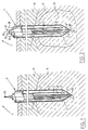
- a rigid hollow needle electrode 1 comprises a proximal end 2, a distal end 3 and there between a longitudinal part 4.
- the electrode 1 comprises a number of cilindrical wall elements 5 forming three concentric channels, i.e. an inner concentric channel 6 and two outer concentric channels 7, 8, which outer concentric channels 7, 8 are connected at the distal end 3 of the electrode 1 forming a closed loop 9.
- the outer concentric channels 7, 8 define a flow path for a cooling solution such that at least the distal end 3 of the electrode 1 can be sufficiently cooled.
- the inner concentric channel 6 is open 10 at the distal end 3.
- the inner concentric channel 6 defines the flow path for the wetting solution and a housing for puncturing means which is formed by an axial (arrow 55) retractable and protruding pith organ 54.
- the pith organ 54 closes the open end 10 when being inserted into the target tumor 11 in order to avoid obstruction in the channel 10.
- An accesory biopsy needle of the same size can be replaced before ablation for sampling tumor tissue for histopathologic examination. After insertion of the electrode 1 the pith organ 54 is retracted upwards making free the flowing path of the wetting solution in the channel 6 (figure 2).
- radio-frequency energy When the electrode 1 is introduced towards a tumor 11 on a target organ 12 radio-frequency energy will be delivered via a non-insulated part of the electrode 1, being at least the distal end 3 of the electrode 1 while simultaneously the distal end 3 is cooled by a cooling solution and the proximity of the distal end 3 is being wetted 13 by a wetting solution.
- the distal end 3 of the electrode 1 is preferably sharpened such that is has a further puncturing function.
- the separate flow control of the cooling and wetting for example in concentration, temperature, etc. results in a superior lesion size.
- the electrode 1 has in general a substantially rigid structure in order to be able to be aimed precisely in the tumor.
- the axial slidable pith organ 54 is used in order not to obstruct the channel for the wetting solution 6. Once the electrode 1 is positioned in the centre of the tumor 11 the pith organ 54 is upwardly retracted and removed. A RF-energy delivery can start when the pith 54 is retracted and the wetting solution 13 is delivered simultaneously with the RF-energy.
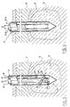
- the embodiment disclosed in figure 3 comprises two concentric channels 27 and 28 forming a closed loop at the closed end 29 of the distal end 30.
- This closed loop channel (27,28) defines the flow channel for the cooling solution as arrows 31 (down) and 32 (up) indicate (comparable to figure 2).
- an open' lateral channel 33 is provided as flow path for the wetting solution, which is preferably a hypertonic saline solution.
- the channel 33 is provided with multiple openings 35 for the outflow of the wetting solution 13 in order to create sufficient spreading of the wetting solution 13 at the proximity of the distal end 30.
- Arrows 36 (down) and 35 (out) define the flow path for the wetting solution.
- the diameter of these needle electrodes should preferably be as small as possible and is preferably smaller than 3 mm.
- the embodiment of the electrode 37 depicted in figure 4 comprises three concentric channels: an outer channel 38 provided with multiple holes 41 at the distal end 42 of the electrode 37 and two concentric channels 27 and 28 forming a closed loop 29 at the distal end 42 of the electrode 37 and defines the flow path for the cooling solution.
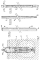
- the electrode of figure 5 discloses another preferred embodiment wherein a separate lateral channel 44 for the wetting solution 13 is provided having at the distal end 45 of the electrode a helical formed part 46 around the distal end 45 of the electrode and is provided with multiple openings 48 in order to create a flow path for the wetting solution through and out the electrode.
- the cooling and wetting solution is one and the same thus. This has the advantages of a more compact and simpler structure of the electrode 49.
- the separate flow rate can be adjusted for their purposes i.e. the cooling solution normally has a higher flow rate than the wetting solution.
- the embodiment of figure 7 discloses a further preferred embodiment comprising an axial (arrow 56) slidable temperature measurement organ 44 comprising multiple thermosensors 50 on a determined distance of each other. Normally radiofrequency radiation and energy will spread radially in relation with the distal end of the' electrode. The retractable thermosensor will provide in an objective manner a measurement of the efficiency of the radiofrequency ablation method.
- thermosensor can be positioned laterally, also the pith can be positioned in a different manner without departing from the scope of the invention.
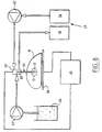
- FIG. 8 depicts a schematic illustration of the radio-frequency ablation of a target tissue 11, for example the liver with a cooled-wet electrode of the invention.
- the cooling means 57 comprise in general a reservoir 58 for a cooling solution connected to an opening 59 at the proximal end 60 of an electrode 61 and further comprising circulation means 62 in order to circulate the cooling solution.
- the wetting means generally contain an infusion pump 63 connected to a hypertonic solution 64 and connected to the opening 59 at the proximal end 60 of the electrode 61.
- the proximal end 60 of the electrode 61 is connected to a radio-frequency energy source 65 and in order to close the electric circuit a ground path 66 is provided under the organ 11.
- the lesion size is substantially enlarged by using a cooled/wet electrode of the invention up to 6-10 cm.
- appropiate temperature control means are further provided at the distal end of the electrode to monitor and to control the temperature. All the depicted configurations of channels and elements in or on the electrode are, as is obvious adjustable and combinable or interchangable.
- Guidance element 100 is substantially formed' by an open elongated shaft 101 provided with a central cilindrical bore 102 and a open blunt distal end 103.
- the diameter of the cilindrical bore 102 is thus adjusted that instruments to be guided by the guidance element 100 can be introduced and be displaced in the axial direction of the bore with a minimal radial tolerance but still providing smooth axial guidance.
- the puncturing can preferably be performed by a puncturing needle 104 which is introduced in the guidance element 100 and provided with a sharpened distal end 106 being used as a puncturing mean for introducing of the combination guidance element 100 and needle 104 towards to the tissue to be treated.
- a smooth introduction can be obtained due to the sharpness and to the form and dimensions of the needle 104.
- the needle 104 is retracted out of the cilindrical bore 102 of the guidance element 100 while maintaining the introduced position of the guidance element 100.
- a radio-frequency electrode can then be entered through the cilindrical bore 102 of the guidance element 100 until protruding at the distal end of the guidance element 100.
- the electrode is retracted out of the guidance element 100, while this element is maintained in the previous obtained position.
- a biopsy needle 109 can be introduced through the same cilindrical bore of the guidance element 100 towards the treated tissue.
- the distal end of the biopsy needle 109 is provided with a clamp 108 for collecting treated tissue samples for further investigation.
- the used equipment comprised a demo RF generator (RFG-3E, Radionics, USA); a cooling pump: Watson-Marlow 31.3 (Watson-Marlow Limt. England); a wetting saline infusion pump (Ismatic, Switzerland); cool-wet electrodes according to the invention and a MRI scanner: 1,5 Tesla Mangetom Vision (Siemens, Er Weg, Germany).
- RFG-3E Radionics, USA
- a cooling pump Watson-Marlow 31.3 (Watson-Marlow Limt. England); a wetting saline infusion pump (Ismatic, Switzerland); cool-wet electrodes according to the invention and a MRI scanner: 1,5 Tesla Mangetom Vision (Siemens, Er Weg, Germany).
- Group A Conventional RF mode, (without cooling perfusion and saline infusion) 2.
- Group B Cooled only mode (RF at 50 W for 10 min with cooling perfusion at 40 ml/min) 3.
- Group C Wet only mode (RF at 50 W for 10 min with 5% saline infusion at 1 ml/min) 4.
- Group D Continuing cooled-wet mode according to the invention (RF at 50 W for 10 min with 5% saline infusion at 1 ml/min and cooling perfusion at 40 ml/min) 5.
- Group E Cooled-wet mode according to the invention with discontinuing saline infusion (RF at 50 W for 10 min with cooling perfusion at 40 ml/min and 5 % saline infusion at 1 ml/min for only first 5 min) 6.
- Group F Cooled-wet mode according to the invention with discontinuing cooling perfusion at 40 ml/min for only first 5 min).
- the inner cavity channel of the electrode is preferably irrigated with cold or tap water.
- the distal end tip of the electrode is maintained at low temperature and free of charring thereby facilitating the conductivity of electrode-tissue interface and preventing an impedance rise.
- the lesion size can no longer be further increased, because
- a hyper-conductive saline as an example of a wetting solution is prior and continuously infused via a the electrode into the target tissue while RF energy is delivered.
- the conductivity of 0,9% normal saline is 3-5 times higher than that of the blood and 12-15 times higher than that of tissues. With more than 5 times of increased concentration, further improvement of conductivity is expected.
- Infused saline functions as a "liquid electrode" within the tissue to be ablated and spreads applied RF energy away from the metal electrode to the surrounding tissue. Therefore, both the central resistive heating rim and peripheral passive heating area are increased, hence a larger lesion can be obtained.
- saline is infused, some convective cooling also occurs at the tip.
- the current invention of cooled-wet electrode combines the advantages and meanwhile overcomes the disadvantages of each separate technique, yielding an optimal result of RF ablation with lesion sizes larger than 6cm. This is realized by an increased conductivity of the target tissue as well as at electrode-tissue interface and a decreased tip temperature. The amount of infused saline can be reduced in comparison to that in "wet" alone mode.
- the present cooled-wet embodiment only use a single needle, through a single puncture but cause a large lesion ideal for tumor ablation or eradication.
- the proposed cooled-wet electrode and the described procedure allows to obtain by a single needle and in one session, a lesion of sufficient size. This is in contrast with the currently existing devices which necessitate either multiple deliveries of expanded electrodes or multiple applications of a single electrode to obtain similar results. Obviously, the application of a single electrode in one session is easier to perform and to control.
Abstract
Description
| Electrode Type | Lesion size (cm) | No. Reference |
| Prototype Electrode | 0,8-1,5 | 1 |
| Bipolar Electrode | 5 (the width between poles) | 2 |
| Cooled Electrode | 1,4 - 3,6 | 3 |
| Wet Electrode | 4,5 ±0,75 | 4 |
| Expandable electrode | 4,5 | 5,6 |
| Cooled-clustered | 4.7 ±0.1 | 7 |
| References cited are: | ||
| 1. Goldberg, S.N. et al. (Academic Radioloqy 1995;2: 399-404) | ||
| 2. Goldberg, S.N. et al. (Acad. Radiol. 3/929, 1996) | ||
| 3. Lorentzen, T.A. (Acad. Radiol. 3:556, 1996) | ||
| 4. Miao, Y. et al. (J. Surg. Res. 71:19, 1997) | ||
| 5. Rossi, S. et al. (AJR. Am. J. Roentgenol., 170: 1015-1022, 1998) | ||
| 6. Patterson EJ, et al. (Ann Surg, 227:559-565, 1998) | ||
| 7. Goldberg S.N. et al. (Radiology 209: 371-379; 1998) The disclosure of document WO-A-98/03220 is considered as closest prior art. |
The subjects of RF ablation are:
| Group | No. Sites | Saline Infusion (ml/min) | Tip Cooling Perfusion (ml/min) | Tip Temp. (°C) | Power Output (W) | Impedance (Ò) | Current (A) | Lesion Size (cm) |
| A | 22 | 0 | 0 | 93,6±3.9 | 13.7±1,5 | >900 | 0,13±0,1 | 0,86±0,3 |
| B | 24 | 0 | 40 | 31,5±4,8 | 16,1±3,3 | 81,2±16,5 | 0,85±0,1 | 2,43±0,5 |
| C | 18 | 1 | 0 | 99,6±0,9 | 45,2±10,8 | 99,8±113,4 | 0,94±0,4 | 3,80±0,5 |
| D | 20 | 1 | 40 | 35,9±6,8 | 49,5±2,4 | 55,8±50,7 | 1,14±0,2 | 4,90±0,6 |
| E | 20 | 1x5min | 40 | 42,9±4,4 | 17,8±2,7 | 725,6±229,3 | 0,15±0,0 | 3,89±0,6 |
| | 13 | 1 | 40x5min | 99,5±0,9 | 38±12,2 | 412,5±138,3 | 0,46±0,4 | 4,27±0,5 |
| Notes: | ||||||||
| 1. Group A: Conventional RF mode, (without cooling perfusion and saline infusion) | ||||||||
| 2. Group B: Cooled only mode (RF at 50 W for 10 min with cooling perfusion at 40 ml/min) | ||||||||
| 3. Group C: Wet only mode (RF at 50 W for 10 min with 5% saline infusion at 1 ml/min) | ||||||||
| 4. Group D: Continuing cooled-wet mode according to the invention (RF at 50 W for 10 min with 5% saline infusion at 1 ml/min and cooling perfusion at 40 ml/min) | ||||||||
| 5. Group E: Cooled-wet mode according to the invention with discontinuing saline infusion (RF at 50 W for 10 min with cooling perfusion at 40 ml/min and 5 % saline infusion at 1 ml/min for only first 5 min) | ||||||||
| 6. Group F: Cooled-wet mode according to the invention with discontinuing cooling perfusion at 40 ml/min for only first 5 min). |
Claims (7)
- Device for delivering radiofrequency (RF) energy, for example during tissue ablation procedures, comprising:tissue puncturing means,an electrode (1) having an unisolated distal end (3) and a proximal end (2) connectable to a radio frequency energy source, andwetting means for wetting the distal end (3) of the electrode (1) and the proximity thereof with a non-toxic (RF) conductive solution wherein the wetting means comprise a first channel (6) which defines a flow path for the wetting solution, and wherein the device further comprises cooling means for cooling at least the distal end (3) of the electrode (1), which cooling means comprise a second channel (7,8) which defines a flowpath for the cooling solution, wherein the wetting channel (6) is open at the distal end (3) of the electrode (1) and wherein the cooling channel (7,8) is closed at the distal end (3) of the electrode (1).
- Device according to claim 1, wherein the channels are concentric.
- Device according to claim 1, wherein the channel defining the flow path for the wetting solution is helical formed at the distal end of the electrode around inner channel for the cooling solution and said helical wetting channel comprises several openings at the distal end.
- Device according to any of the previous claims, wherein the distal end of the electrode is provided with retractable temperature control means preferable comprising at least two temperature sensors.
- Device according to any of the previous claims, wherein the electrode is formed by a cluster of several, for example 2, 3, 4 or more separate electrodes in a parallel alignment.
- Device according to any of the previous claims, wherein the puncturing means are associated with the unisolated distal end (3) of the electrode (1).
- Device according to any of the previous claims wherein tissue puncturing means are formed by an inner axial slidable pith organ (54).
Applications Claiming Priority (3)
| Application Number | Priority Date | Filing Date | Title |
|---|---|---|---|
| NL1009868 | 1998-08-14 | ||
| NL1009868 | 1998-08-14 | ||
| PCT/BE1999/000106 WO2000009208A1 (en) | 1998-08-14 | 1999-08-13 | Cooled-wet electrode |
Publications (2)
| Publication Number | Publication Date |
|---|---|
| EP1104327A1 EP1104327A1 (en) | 2001-06-06 |
| EP1104327B1 true EP1104327B1 (en) | 2004-10-27 |
Family
ID=19767651
Family Applications (2)
| Application Number | Title | Priority Date | Filing Date |
|---|---|---|---|
| EP99939867A Withdrawn EP1104328A1 (en) | 1998-08-14 | 1999-08-13 | Expandable wet electrode |
| EP99939273A Expired - Lifetime EP1104327B1 (en) | 1998-08-14 | 1999-08-13 | Cooled-wet electrode |
Family Applications Before (1)
| Application Number | Title | Priority Date | Filing Date |
|---|---|---|---|
| EP99939867A Withdrawn EP1104328A1 (en) | 1998-08-14 | 1999-08-13 | Expandable wet electrode |
Country Status (9)
| Country | Link |
|---|---|
| US (1) | US6514251B1 (en) |
| EP (2) | EP1104328A1 (en) |
| JP (2) | JP4138249B2 (en) |
| CN (2) | CN1323234A (en) |
| AT (1) | ATE280617T1 (en) |
| AU (2) | AU5365599A (en) |
| DE (1) | DE69921482T2 (en) |
| ES (1) | ES2228083T3 (en) |
| WO (2) | WO2000009208A1 (en) |
Families Citing this family (100)
| Publication number | Priority date | Publication date | Assignee | Title |
|---|---|---|---|---|
| US6641580B1 (en) | 1993-11-08 | 2003-11-04 | Rita Medical Systems, Inc. | Infusion array ablation apparatus |
| US6569159B1 (en) | 1993-11-08 | 2003-05-27 | Rita Medical Systems, Inc. | Cell necrosis apparatus |
| US5536267A (en) | 1993-11-08 | 1996-07-16 | Zomed International | Multiple electrode ablation apparatus |
| US6632221B1 (en) | 1993-11-08 | 2003-10-14 | Rita Medical Systems, Inc. | Method of creating a lesion in tissue with infusion |
| US6059780A (en) | 1995-08-15 | 2000-05-09 | Rita Medical Systems, Inc. | Multiple antenna ablation apparatus and method with cooling element |
| US6726686B2 (en) * | 1997-11-12 | 2004-04-27 | Sherwood Services Ag | Bipolar electrosurgical instrument for sealing vessels |
| US7435249B2 (en) * | 1997-11-12 | 2008-10-14 | Covidien Ag | Electrosurgical instruments which reduces collateral damage to adjacent tissue |
| US6352536B1 (en) * | 2000-02-11 | 2002-03-05 | Sherwood Services Ag | Bipolar electrosurgical instrument for sealing vessels |
| US7582087B2 (en) * | 1998-10-23 | 2009-09-01 | Covidien Ag | Vessel sealing instrument |
| US20040249374A1 (en) * | 1998-10-23 | 2004-12-09 | Tetzlaff Philip M. | Vessel sealing instrument |
| DE102004033595A1 (en) * | 2004-07-07 | 2006-02-16 | Celon Ag Medical Instruments | Bipolar coagulation electrode |
| US6306132B1 (en) * | 1999-06-17 | 2001-10-23 | Vivant Medical | Modular biopsy and microwave ablation needle delivery apparatus adapted to in situ assembly and method of use |
| US6770070B1 (en) * | 2000-03-17 | 2004-08-03 | Rita Medical Systems, Inc. | Lung treatment apparatus and method |
| AU5113401A (en) * | 2000-03-31 | 2001-10-15 | Rita Medical Systems Inc | Tissue biopsy and treatment apparatus and method |
| US20020022864A1 (en) * | 2000-06-07 | 2002-02-21 | Mahvi David M. | Multipolar electrode system for radiofrequency ablation |
| US7101373B2 (en) * | 2001-04-06 | 2006-09-05 | Sherwood Services Ag | Vessel sealer and divider |
| DE60121229T2 (en) * | 2001-04-06 | 2007-05-24 | Sherwood Services Ag | DEVICE FOR SEALING AND SHARING A VESSEL WITH NON-LASTING END STOP |
| CA2442852C (en) * | 2001-04-06 | 2011-07-26 | Sherwood Services Ag | Molded insulating hinge for bipolar instruments |
| US7090673B2 (en) * | 2001-04-06 | 2006-08-15 | Sherwood Services Ag | Vessel sealer and divider |
| US7118587B2 (en) * | 2001-04-06 | 2006-10-10 | Sherwood Services Ag | Vessel sealer and divider |
| US10849681B2 (en) | 2001-04-06 | 2020-12-01 | Covidien Ag | Vessel sealer and divider |
| US7101372B2 (en) * | 2001-04-06 | 2006-09-05 | Sherwood Sevices Ag | Vessel sealer and divider |
| DE10128701B4 (en) | 2001-06-07 | 2005-06-23 | Celon Ag Medical Instruments | probe assembly |
| AU2002327779B2 (en) | 2001-09-28 | 2008-06-26 | Angiodynamics, Inc. | Impedance controlled tissue ablation apparatus and method |
| US6878147B2 (en) | 2001-11-02 | 2005-04-12 | Vivant Medical, Inc. | High-strength microwave antenna assemblies |
| US7128739B2 (en) * | 2001-11-02 | 2006-10-31 | Vivant Medical, Inc. | High-strength microwave antenna assemblies and methods of use |
| US8882755B2 (en) * | 2002-03-05 | 2014-11-11 | Kimberly-Clark Inc. | Electrosurgical device for treatment of tissue |
| US20040115296A1 (en) * | 2002-04-05 | 2004-06-17 | Duffin Terry M. | Retractable overmolded insert retention apparatus |
| US6752767B2 (en) * | 2002-04-16 | 2004-06-22 | Vivant Medical, Inc. | Localization element with energized tip |
| US7197363B2 (en) | 2002-04-16 | 2007-03-27 | Vivant Medical, Inc. | Microwave antenna having a curved configuration |
| US6887237B2 (en) | 2002-07-22 | 2005-05-03 | Medtronic, Inc. | Method for treating tissue with a wet electrode and apparatus for using same |
| US7799026B2 (en) | 2002-11-14 | 2010-09-21 | Covidien Ag | Compressible jaw configuration with bipolar RF output electrodes for soft tissue fusion |
| US20040181214A1 (en) * | 2003-03-13 | 2004-09-16 | Garabedian Robert J. | Passively cooled array |
| US7344530B2 (en) * | 2003-03-26 | 2008-03-18 | Regents Of The University Of Minnesota | Thermal surgical procedures and compositions |
| KR100466866B1 (en) * | 2003-04-24 | 2005-01-24 | 전명기 | Electrode for radiofrequency tissue ablation |
| US7160299B2 (en) * | 2003-05-01 | 2007-01-09 | Sherwood Services Ag | Method of fusing biomaterials with radiofrequency energy |
| CA2523675C (en) * | 2003-05-01 | 2016-04-26 | Sherwood Services Ag | Electrosurgical instrument which reduces thermal damage to adjacent tissue |
| USD499181S1 (en) | 2003-05-15 | 2004-11-30 | Sherwood Services Ag | Handle for a vessel sealer and divider |
| AU2004241092B2 (en) * | 2003-05-15 | 2009-06-04 | Covidien Ag | Tissue sealer with non-conductive variable stop members and method of sealing tissue |
| USD496997S1 (en) | 2003-05-15 | 2004-10-05 | Sherwood Services Ag | Vessel sealer and divider |
| US7311703B2 (en) | 2003-07-18 | 2007-12-25 | Vivant Medical, Inc. | Devices and methods for cooling microwave antennas |
| US9848938B2 (en) | 2003-11-13 | 2017-12-26 | Covidien Ag | Compressible jaw configuration with bipolar RF output electrodes for soft tissue fusion |
| US7252667B2 (en) * | 2003-11-19 | 2007-08-07 | Sherwood Services Ag | Open vessel sealing instrument with cutting mechanism and distal lockout |
| US7442193B2 (en) * | 2003-11-20 | 2008-10-28 | Covidien Ag | Electrically conductive/insulative over-shoe for tissue fusion |
| US7074494B2 (en) * | 2004-02-19 | 2006-07-11 | E. I. Du Pont De Nemours And Company | Flame retardant surface coverings |
| WO2005096953A1 (en) * | 2004-03-31 | 2005-10-20 | Wilson-Cook Medical Inc. | Biopsy needle system |
| CN1296014C (en) * | 2004-06-17 | 2007-01-24 | 上海交通大学 | Water-cooled radio frequency system for tumour extinguishing |
| GB2415630C2 (en) * | 2004-07-02 | 2007-03-22 | Microsulis Ltd | Radiation applicator and method of radiating tissue |
| US7156570B2 (en) * | 2004-12-30 | 2007-01-02 | Cotapaxi Custom Design And Manufacturing, Llc | Implement grip |
| US7799019B2 (en) | 2005-05-10 | 2010-09-21 | Vivant Medical, Inc. | Reinforced high strength microwave antenna |
| DE102005023303A1 (en) * | 2005-05-13 | 2006-11-16 | Celon Ag Medical Instruments | Biegeweiche application device for high-frequency therapy of biological tissue |
| US20070055225A1 (en) * | 2005-09-07 | 2007-03-08 | Dodd Gerald D Iii | Method and apparatus for electromagnetic ablation of biological tissue |
| US7704248B2 (en) | 2005-12-21 | 2010-04-27 | Boston Scientific Scimed, Inc. | Ablation device with compression balloon |
| US20070179491A1 (en) * | 2006-01-31 | 2007-08-02 | Medtronic, Inc. | Sensing needle for ablation therapy |
| US9414883B2 (en) | 2006-06-09 | 2016-08-16 | Boston Scientific Scimed, Inc. | Co-access foam/electrode introducer |
| US8068921B2 (en) | 2006-09-29 | 2011-11-29 | Vivant Medical, Inc. | Microwave antenna assembly and method of using the same |
| CN100594008C (en) * | 2007-01-16 | 2010-03-17 | 盛林 | Microwave ablation water knife |
| US7998139B2 (en) | 2007-04-25 | 2011-08-16 | Vivant Medical, Inc. | Cooled helical antenna for microwave ablation |
| ES2307426B2 (en) * | 2007-04-30 | 2009-10-01 | Universidad Politecnica De Valencia | APPLICATOR DEVICE FOR RADIOFREQUENCY ABLATION OF BIOLOGICAL FABRICS. |
| US8353901B2 (en) * | 2007-05-22 | 2013-01-15 | Vivant Medical, Inc. | Energy delivery conduits for use with electrosurgical devices |
| US9023024B2 (en) | 2007-06-20 | 2015-05-05 | Covidien Lp | Reflective power monitoring for microwave applications |
| US20090005766A1 (en) * | 2007-06-28 | 2009-01-01 | Joseph Brannan | Broadband microwave applicator |
| US8651146B2 (en) | 2007-09-28 | 2014-02-18 | Covidien Lp | Cable stand-off |
| US8292880B2 (en) * | 2007-11-27 | 2012-10-23 | Vivant Medical, Inc. | Targeted cooling of deployable microwave antenna |
| US8998892B2 (en) | 2007-12-21 | 2015-04-07 | Atricure, Inc. | Ablation device with cooled electrodes and methods of use |
| US8353907B2 (en) * | 2007-12-21 | 2013-01-15 | Atricure, Inc. | Ablation device with internally cooled electrodes |
| US9198723B2 (en) * | 2008-03-31 | 2015-12-01 | Covidien Lp | Re-hydration antenna for ablation |
| KR101108569B1 (en) * | 2008-05-15 | 2012-01-30 | 전명기 | Electrode for radiofrequency tissue ablation |
| US8328804B2 (en) * | 2008-07-24 | 2012-12-11 | Covidien Lp | Suction coagulator |
| US9332973B2 (en) | 2008-10-01 | 2016-05-10 | Covidien Lp | Needle biopsy device with exchangeable needle and integrated needle protection |
| US11298113B2 (en) | 2008-10-01 | 2022-04-12 | Covidien Lp | Device for needle biopsy with integrated needle protection |
| US9186128B2 (en) | 2008-10-01 | 2015-11-17 | Covidien Lp | Needle biopsy device |
| US9782565B2 (en) | 2008-10-01 | 2017-10-10 | Covidien Lp | Endoscopic ultrasound-guided biliary access system |
| US8968210B2 (en) * | 2008-10-01 | 2015-03-03 | Covidien LLP | Device for needle biopsy with integrated needle protection |
| US8728068B2 (en) * | 2009-04-09 | 2014-05-20 | Urologix, Inc. | Cooled antenna for device insertable into a body |
| US9855094B2 (en) * | 2010-12-28 | 2018-01-02 | St. Jude Medical, Atrial Fibrillation Division, Inc. | Multi-rate fluid flow and variable power delivery for ablation electrode assemblies used in catheter ablation procedures |
| US9486275B2 (en) * | 2010-12-30 | 2016-11-08 | Avent, Inc. | Electrosurgical apparatus having a sensor |
| US9044245B2 (en) * | 2011-01-05 | 2015-06-02 | Medtronic Ablation Frontiers Llc | Multipolarity epicardial radiofrequency ablation |
| ES2864589T3 (en) | 2011-04-12 | 2021-10-14 | Thermedical Inc | Devices for conformal therapy in fluid-enhanced ablation |
| CN106823131B (en) * | 2011-09-30 | 2019-12-20 | 柯惠有限合伙公司 | Energy transfer device and method of use |
| KR101449965B1 (en) | 2012-02-10 | 2014-10-15 | (주)알에프메디컬 | Electrode tip for radiofrequency tissue ablation and electrode having the same |
| CN102626329B (en) * | 2012-03-13 | 2014-10-15 | 郑州大学 | Radiofrequency ablation negative pressure automatic biopsy gun |
| US9101344B2 (en) | 2013-03-15 | 2015-08-11 | Covidien Lp | Recirculating cooling system for energy delivery device |
| US9682190B2 (en) | 2013-03-15 | 2017-06-20 | Covidien Lp | Recirculating cooling system for energy delivery device |
| US9872719B2 (en) | 2013-07-24 | 2018-01-23 | Covidien Lp | Systems and methods for generating electrosurgical energy using a multistage power converter |
| US9636165B2 (en) | 2013-07-29 | 2017-05-02 | Covidien Lp | Systems and methods for measuring tissue impedance through an electrosurgical cable |
| US10646267B2 (en) | 2013-08-07 | 2020-05-12 | Covidien LLP | Surgical forceps |
| CN104207842A (en) * | 2014-09-28 | 2014-12-17 | 大连顺达微创科技有限公司 | Rotary liquid feeding type plasma operation electrode |
| CN104287828A (en) * | 2014-10-20 | 2015-01-21 | 周稼 | Flexible hollow radiofrequency treatment electrode |
| CN104958104B (en) * | 2015-06-30 | 2017-07-21 | 绍兴市人民医院 | Split type radio frequency needle |
| US9987078B2 (en) | 2015-07-22 | 2018-06-05 | Covidien Lp | Surgical forceps |
| US10631918B2 (en) | 2015-08-14 | 2020-04-28 | Covidien Lp | Energizable surgical attachment for a mechanical clamp |
| US9743984B1 (en) | 2016-08-11 | 2017-08-29 | Thermedical, Inc. | Devices and methods for delivering fluid to tissue during ablation therapy |
| JP7049326B2 (en) | 2016-10-04 | 2022-04-06 | アヴェント インコーポレイテッド | Cooled RF probe |
| US11166759B2 (en) | 2017-05-16 | 2021-11-09 | Covidien Lp | Surgical forceps |
| US11071586B2 (en) | 2017-06-05 | 2021-07-27 | Covidien Lp | Cooling systems for energy delivery devices |
| JP6840649B2 (en) * | 2017-10-13 | 2021-03-10 | 日本ライフライン株式会社 | Radiofrequency treatment catheter |
| US11083871B2 (en) | 2018-05-03 | 2021-08-10 | Thermedical, Inc. | Selectively deployable catheter ablation devices |
| US11918277B2 (en) | 2018-07-16 | 2024-03-05 | Thermedical, Inc. | Inferred maximum temperature monitoring for irrigated ablation therapy |
| US11382682B2 (en) | 2018-11-28 | 2022-07-12 | Boston Scientific Scimed, Inc. | Closed irrigated radiofrequency bipolar tined ablation probe |
Family Cites Families (9)
| Publication number | Priority date | Publication date | Assignee | Title |
|---|---|---|---|---|
| CA1244889A (en) | 1983-01-24 | 1988-11-15 | Kureha Chemical Ind Co Ltd | Device for hyperthermia |
| US5843019A (en) | 1992-01-07 | 1998-12-01 | Arthrocare Corporation | Shaped electrodes and methods for electrosurgical cutting and ablation |
| US5681282A (en) * | 1992-01-07 | 1997-10-28 | Arthrocare Corporation | Methods and apparatus for ablation of luminal tissues |
| US5431649A (en) * | 1993-08-27 | 1995-07-11 | Medtronic, Inc. | Method and apparatus for R-F ablation |
| US5536267A (en) * | 1993-11-08 | 1996-07-16 | Zomed International | Multiple electrode ablation apparatus |
| US5472441A (en) * | 1993-11-08 | 1995-12-05 | Zomed International | Device for treating cancer and non-malignant tumors and methods |
| US6106524A (en) * | 1995-03-03 | 2000-08-22 | Neothermia Corporation | Methods and apparatus for therapeutic cauterization of predetermined volumes of biological tissue |
| US5688267A (en) * | 1995-05-01 | 1997-11-18 | Ep Technologies, Inc. | Systems and methods for sensing multiple temperature conditions during tissue ablation |
| WO1997006741A2 (en) * | 1995-08-18 | 1997-02-27 | Somnus Medical Technologies, Inc. | Apparatus for cosmetically remodeling a body structure |
-
1999
- 1999-08-13 JP JP2000564709A patent/JP4138249B2/en not_active Expired - Fee Related
- 1999-08-13 JP JP2000564710A patent/JP2002522183A/en active Pending
- 1999-08-13 WO PCT/BE1999/000106 patent/WO2000009208A1/en active IP Right Grant
- 1999-08-13 US US09/762,728 patent/US6514251B1/en not_active Expired - Fee Related
- 1999-08-13 CN CN99812155.XA patent/CN1323234A/en active Pending
- 1999-08-13 DE DE69921482T patent/DE69921482T2/en not_active Expired - Lifetime
- 1999-08-13 AU AU53655/99A patent/AU5365599A/en not_active Abandoned
- 1999-08-13 AU AU54028/99A patent/AU5402899A/en not_active Abandoned
- 1999-08-13 AT AT99939273T patent/ATE280617T1/en not_active IP Right Cessation
- 1999-08-13 ES ES99939273T patent/ES2228083T3/en not_active Expired - Lifetime
- 1999-08-13 CN CN99812151.7A patent/CN1191873C/en not_active Expired - Fee Related
- 1999-08-13 EP EP99939867A patent/EP1104328A1/en not_active Withdrawn
- 1999-08-13 EP EP99939273A patent/EP1104327B1/en not_active Expired - Lifetime
- 1999-08-13 WO PCT/BE1999/000107 patent/WO2000009209A1/en not_active Application Discontinuation
Also Published As
| Publication number | Publication date |
|---|---|
| ATE280617T1 (en) | 2004-11-15 |
| WO2000009208A1 (en) | 2000-02-24 |
| AU5402899A (en) | 2000-03-06 |
| JP4138249B2 (en) | 2008-08-27 |
| CN1191873C (en) | 2005-03-09 |
| AU5365599A (en) | 2000-03-06 |
| WO2000009209A1 (en) | 2000-02-24 |
| DE69921482D1 (en) | 2004-12-02 |
| JP2002522183A (en) | 2002-07-23 |
| ES2228083T3 (en) | 2005-04-01 |
| EP1104328A1 (en) | 2001-06-06 |
| CN1323233A (en) | 2001-11-21 |
| DE69921482T2 (en) | 2005-12-15 |
| CN1323234A (en) | 2001-11-21 |
| EP1104327A1 (en) | 2001-06-06 |
| US6514251B1 (en) | 2003-02-04 |
| JP2002522182A (en) | 2002-07-23 |
Similar Documents
| Publication | Publication Date | Title |
|---|---|---|
| EP1104327B1 (en) | Cooled-wet electrode | |
| Goldberg et al. | Tissue ablation with radiofrequency: effect of probe size, gauge, duration, and temperature on lesion volume | |
| McGahan et al. | Hepatic ablation using bipolar radiofrequency electrocautery | |
| US7238184B2 (en) | Ablation probe with peltier effect thermal control | |
| US7101387B2 (en) | Radio frequency ablation cooling shield | |
| US20040181214A1 (en) | Passively cooled array | |
| US5951546A (en) | Electrosurgical instrument for tissue ablation, an apparatus, and a method for providing a lesion in damaged and diseased tissue from a mammal | |
| JP3560917B2 (en) | Ablation device | |
| US6470218B1 (en) | Apparatus and method for treating tumors near the surface of an organ | |
| EP2143394B1 (en) | Applicator device for ablation by radiofrequency of biological tissues | |
| US8414580B2 (en) | Co-access bipolar ablation probe | |
| US7749219B2 (en) | Method for indirectly ablating tissue using implanted electrode device | |
| US9814519B2 (en) | Ablation probe with ribbed insulated sheath | |
| US20070185483A1 (en) | Saline-enhanced catheter for radiofrequency tumor ablation | |
| US20120226271A1 (en) | Vacuum Ablation Apparatus and Method | |
| US7182761B2 (en) | Ablation probe with temperature sensitive electrode array | |
| KR20160003543U (en) | Bipolar radio frequency ablation instrument with offset electrodes | |
| McGahan et al. | History of ablation | |
| JP2008513154A (en) | Apparatus and method for cryosurgery | |
| Ahmed et al. | Effect of Radio Frequency Irradiation on Hepatocarcinoma |
Legal Events
| Date | Code | Title | Description |
|---|---|---|---|
| PUAI | Public reference made under article 153(3) epc to a published international application that has entered the european phase |
Free format text: ORIGINAL CODE: 0009012 |
|
| 17P | Request for examination filed |
Effective date: 20010126 |
|
| AK | Designated contracting states |
Kind code of ref document: A1 Designated state(s): AT BE CH CY DE DK ES FI FR GB GR IE IT LI LU MC NL PT SE |
|
| GRAP | Despatch of communication of intention to grant a patent |
Free format text: ORIGINAL CODE: EPIDOSNIGR1 |
|
| GRAS | Grant fee paid |
Free format text: ORIGINAL CODE: EPIDOSNIGR3 |
|
| GRAA | (expected) grant |
Free format text: ORIGINAL CODE: 0009210 |
|
| AK | Designated contracting states |
Kind code of ref document: B1 Designated state(s): AT BE CH CY DE DK ES FI FR GB GR IE IT LI LU MC NL PT SE |
|
| PG25 | Lapsed in a contracting state [announced via postgrant information from national office to epo] |
Ref country code: NL Free format text: LAPSE BECAUSE OF FAILURE TO SUBMIT A TRANSLATION OF THE DESCRIPTION OR TO PAY THE FEE WITHIN THE PRESCRIBED TIME-LIMIT Effective date: 20041027 Ref country code: LI Free format text: LAPSE BECAUSE OF FAILURE TO SUBMIT A TRANSLATION OF THE DESCRIPTION OR TO PAY THE FEE WITHIN THE PRESCRIBED TIME-LIMIT Effective date: 20041027 Ref country code: FI Free format text: LAPSE BECAUSE OF FAILURE TO SUBMIT A TRANSLATION OF THE DESCRIPTION OR TO PAY THE FEE WITHIN THE PRESCRIBED TIME-LIMIT Effective date: 20041027 Ref country code: CH Free format text: LAPSE BECAUSE OF FAILURE TO SUBMIT A TRANSLATION OF THE DESCRIPTION OR TO PAY THE FEE WITHIN THE PRESCRIBED TIME-LIMIT Effective date: 20041027 Ref country code: BE Free format text: LAPSE BECAUSE OF FAILURE TO SUBMIT A TRANSLATION OF THE DESCRIPTION OR TO PAY THE FEE WITHIN THE PRESCRIBED TIME-LIMIT Effective date: 20041027 Ref country code: AT Free format text: LAPSE BECAUSE OF FAILURE TO SUBMIT A TRANSLATION OF THE DESCRIPTION OR TO PAY THE FEE WITHIN THE PRESCRIBED TIME-LIMIT Effective date: 20041027 |
|
| REG | Reference to a national code |
Ref country code: GB Ref legal event code: FG4D |
|
| REG | Reference to a national code |
Ref country code: CH Ref legal event code: EP |
|
| REG | Reference to a national code |
Ref country code: IE Ref legal event code: FG4D |
|
| REF | Corresponds to: |
Ref document number: 69921482 Country of ref document: DE Date of ref document: 20041202 Kind code of ref document: P |
|
| PG25 | Lapsed in a contracting state [announced via postgrant information from national office to epo] |
Ref country code: SE Free format text: LAPSE BECAUSE OF FAILURE TO SUBMIT A TRANSLATION OF THE DESCRIPTION OR TO PAY THE FEE WITHIN THE PRESCRIBED TIME-LIMIT Effective date: 20050127 Ref country code: GR Free format text: LAPSE BECAUSE OF FAILURE TO SUBMIT A TRANSLATION OF THE DESCRIPTION OR TO PAY THE FEE WITHIN THE PRESCRIBED TIME-LIMIT Effective date: 20050127 Ref country code: DK Free format text: LAPSE BECAUSE OF FAILURE TO SUBMIT A TRANSLATION OF THE DESCRIPTION OR TO PAY THE FEE WITHIN THE PRESCRIBED TIME-LIMIT Effective date: 20050127 |
|
| REG | Reference to a national code |
Ref country code: ES Ref legal event code: FG2A Ref document number: 2228083 Country of ref document: ES Kind code of ref document: T3 |
|
| REG | Reference to a national code |
Ref country code: CH Ref legal event code: PL |
|
| NLV1 | Nl: lapsed or annulled due to failure to fulfill the requirements of art. 29p and 29m of the patents act | ||
| ET | Fr: translation filed | ||
| PG25 | Lapsed in a contracting state [announced via postgrant information from national office to epo] |
Ref country code: LU Free format text: LAPSE BECAUSE OF NON-PAYMENT OF DUE FEES Effective date: 20050813 Ref country code: CY Free format text: LAPSE BECAUSE OF FAILURE TO SUBMIT A TRANSLATION OF THE DESCRIPTION OR TO PAY THE FEE WITHIN THE PRESCRIBED TIME-LIMIT Effective date: 20050813 |
|
| PG25 | Lapsed in a contracting state [announced via postgrant information from national office to epo] |
Ref country code: IE Free format text: LAPSE BECAUSE OF NON-PAYMENT OF DUE FEES Effective date: 20050815 |
|
| PG25 | Lapsed in a contracting state [announced via postgrant information from national office to epo] |
Ref country code: MC Free format text: LAPSE BECAUSE OF NON-PAYMENT OF DUE FEES Effective date: 20050831 |
|
| PLBE | No opposition filed within time limit |
Free format text: ORIGINAL CODE: 0009261 |
|
| STAA | Information on the status of an ep patent application or granted ep patent |
Free format text: STATUS: NO OPPOSITION FILED WITHIN TIME LIMIT |
|
| 26N | No opposition filed |
Effective date: 20050728 |
|
| REG | Reference to a national code |
Ref country code: IE Ref legal event code: MM4A |
|
| PG25 | Lapsed in a contracting state [announced via postgrant information from national office to epo] |
Ref country code: PT Free format text: LAPSE BECAUSE OF NON-PAYMENT OF DUE FEES Effective date: 20050327 |
|
| PGFP | Annual fee paid to national office [announced via postgrant information from national office to epo] |
Ref country code: ES Payment date: 20100831 Year of fee payment: 12 |
|
| PGFP | Annual fee paid to national office [announced via postgrant information from national office to epo] |
Ref country code: IT Payment date: 20100830 Year of fee payment: 12 Ref country code: FR Payment date: 20100914 Year of fee payment: 12 Ref country code: DE Payment date: 20100831 Year of fee payment: 12 |
|
| PGFP | Annual fee paid to national office [announced via postgrant information from national office to epo] |
Ref country code: GB Payment date: 20100825 Year of fee payment: 12 |
|
| GBPC | Gb: european patent ceased through non-payment of renewal fee |
Effective date: 20110813 |
|
| REG | Reference to a national code |
Ref country code: FR Ref legal event code: ST Effective date: 20120430 |
|
| PG25 | Lapsed in a contracting state [announced via postgrant information from national office to epo] |
Ref country code: IT Free format text: LAPSE BECAUSE OF NON-PAYMENT OF DUE FEES Effective date: 20110813 |
|
| REG | Reference to a national code |
Ref country code: DE Ref legal event code: R119 Ref document number: 69921482 Country of ref document: DE Effective date: 20120301 |
|
| PG25 | Lapsed in a contracting state [announced via postgrant information from national office to epo] |
Ref country code: FR Free format text: LAPSE BECAUSE OF NON-PAYMENT OF DUE FEES Effective date: 20110831 Ref country code: GB Free format text: LAPSE BECAUSE OF NON-PAYMENT OF DUE FEES Effective date: 20110813 |
|
| REG | Reference to a national code |
Ref country code: ES Ref legal event code: FD2A Effective date: 20121207 |
|
| PG25 | Lapsed in a contracting state [announced via postgrant information from national office to epo] |
Ref country code: ES Free format text: LAPSE BECAUSE OF NON-PAYMENT OF DUE FEES Effective date: 20110814 |
|
| PG25 | Lapsed in a contracting state [announced via postgrant information from national office to epo] |
Ref country code: DE Free format text: LAPSE BECAUSE OF NON-PAYMENT OF DUE FEES Effective date: 20120301 |