EP1106550A1 - Device and method for transporting complementary product - Google Patents
Device and method for transporting complementary product Download PDFInfo
- Publication number
- EP1106550A1 EP1106550A1 EP00125755A EP00125755A EP1106550A1 EP 1106550 A1 EP1106550 A1 EP 1106550A1 EP 00125755 A EP00125755 A EP 00125755A EP 00125755 A EP00125755 A EP 00125755A EP 1106550 A1 EP1106550 A1 EP 1106550A1
- Authority
- EP
- European Patent Office
- Prior art keywords
- supplementary
- products
- supplementary products
- conveyor
- point
- Prior art date
- Legal status (The legal status is an assumption and is not a legal conclusion. Google has not performed a legal analysis and makes no representation as to the accuracy of the status listed.)
- Granted
Links
Images


Classifications
-
- B—PERFORMING OPERATIONS; TRANSPORTING
- B65—CONVEYING; PACKING; STORING; HANDLING THIN OR FILAMENTARY MATERIAL
- B65H—HANDLING THIN OR FILAMENTARY MATERIAL, e.g. SHEETS, WEBS, CABLES
- B65H5/00—Feeding articles separated from piles; Feeding articles to machines
- B65H5/08—Feeding articles separated from piles; Feeding articles to machines by grippers, e.g. suction grippers
- B65H5/12—Revolving grippers, e.g. mounted on arms, frames or cylinders
-
- B—PERFORMING OPERATIONS; TRANSPORTING
- B65—CONVEYING; PACKING; STORING; HANDLING THIN OR FILAMENTARY MATERIAL
- B65H—HANDLING THIN OR FILAMENTARY MATERIAL, e.g. SHEETS, WEBS, CABLES
- B65H29/00—Delivering or advancing articles from machines; Advancing articles to or into piles
- B65H29/003—Delivering or advancing articles from machines; Advancing articles to or into piles by grippers
-
- B—PERFORMING OPERATIONS; TRANSPORTING
- B65—CONVEYING; PACKING; STORING; HANDLING THIN OR FILAMENTARY MATERIAL
- B65H—HANDLING THIN OR FILAMENTARY MATERIAL, e.g. SHEETS, WEBS, CABLES
- B65H2301/00—Handling processes for sheets or webs
- B65H2301/30—Orientation, displacement, position of the handled material
- B65H2301/33—Modifying, selecting, changing orientation
-
- B—PERFORMING OPERATIONS; TRANSPORTING
- B65—CONVEYING; PACKING; STORING; HANDLING THIN OR FILAMENTARY MATERIAL
- B65H—HANDLING THIN OR FILAMENTARY MATERIAL, e.g. SHEETS, WEBS, CABLES
- B65H2405/00—Parts for holding the handled material
- B65H2405/50—Gripping means
- B65H2405/58—Means for achieving gripping/releasing operation
- B65H2405/583—Details of gripper orientation
- B65H2405/5831—Gripping mouth orientated in direction of gripper displacement
-
- B—PERFORMING OPERATIONS; TRANSPORTING
- B65—CONVEYING; PACKING; STORING; HANDLING THIN OR FILAMENTARY MATERIAL
- B65H—HANDLING THIN OR FILAMENTARY MATERIAL, e.g. SHEETS, WEBS, CABLES
- B65H2405/00—Parts for holding the handled material
- B65H2405/50—Gripping means
- B65H2405/58—Means for achieving gripping/releasing operation
- B65H2405/583—Details of gripper orientation
- B65H2405/5832—Details of gripper orientation and varying its orientation after gripping
-
- Y—GENERAL TAGGING OF NEW TECHNOLOGICAL DEVELOPMENTS; GENERAL TAGGING OF CROSS-SECTIONAL TECHNOLOGIES SPANNING OVER SEVERAL SECTIONS OF THE IPC; TECHNICAL SUBJECTS COVERED BY FORMER USPC CROSS-REFERENCE ART COLLECTIONS [XRACs] AND DIGESTS
- Y10—TECHNICAL SUBJECTS COVERED BY FORMER USPC
- Y10T—TECHNICAL SUBJECTS COVERED BY FORMER US CLASSIFICATION
- Y10T156/00—Adhesive bonding and miscellaneous chemical manufacture
- Y10T156/17—Surface bonding means and/or assemblymeans with work feeding or handling means
- Y10T156/1702—For plural parts or plural areas of single part
- Y10T156/1744—Means bringing discrete articles into assembled relationship
- Y10T156/1768—Means simultaneously conveying plural articles from a single source and serially presenting them to an assembly station
- Y10T156/1771—Turret or rotary drum-type conveyor
- Y10T156/1773—For flexible sheets
Definitions
- the invention relates to an apparatus and a method for the transport of, in particular, adhesives flat supplementary products from a reception center a delivery point according to the preamble of claim 1 or 16.
- the Supplementary products can be stacked, for example or from a roll Strip or tape can be separated.
- This tape can be a Be a carrier tape on which the supplementary products adhere, detached from that during the funding process, by a Generic device detected and to the delivery location transported and then directly, if necessary also by another tool with which Printing products.
- the strip or that However, tape can also be the basis of complementary products form, separated from the strip and, if necessary further processed, if necessary with a Adhesives are provided.
- Adhesive layer If a for the supplementary products supplied Adhesive layer is needed, this is in relation to the Direction of conveyance normally in the form of a Stripe provided on the supplementary products.
- the Apply a continuous one in the longitudinal direction Adhesive tape on a tape is much easier than the application of horizontal stripes in sections, which also to synchronize with a detaching tool are.
- Even when using a carrier tape are the supplementary products adhering to it preferably in Direction of conveyance laterally with a strip forming Provide adhesive layer.
- the carrier tape e.g. by one leading edge forming an acute angle, run the coated with an adhesive Supplementary products detached from the carrier tape continue in Direction of conveyance.
- WO 99/06285 Device Such is known from the published patent application WO 99/06285 Device known. It shows a feed conveyor through the one on the side with an adhesive layer strip provided tape is fed to a cutting device, which supplementary products separate from this volume. The separated supplementary products are by means of a Suction tool or a roller fed to a rotor, the this by means of gripping or suction elements in relation to the Feed or strip longitudinal direction recorded laterally, to a Delivery point leads and there with a printed product connects and releases.
- the funding direction of the Complementary products are on the feed conveyor perpendicular to the plane in which the laterally captured Complementary products are transported by the rotor and in which also includes the printed products to be loaded are guided tangentially past the rotor.
- the supplementary products related to feed direction laterally with a stripe Are provided by the rotor detected that the applied to the adhesive layer strips Edge of the supplementary product in relation to the direction of rotation of the rotor runs on.
- the present invention is therefore based on the object based on a powerful, universally applicable To create device and specify a method by by a first sponsor in a first location supplied supplementary products recorded, to a second Transported and there in one for the conveyor Submitted further processing suitable second layer can be.
- the admission point provided for one at a second conveyor intended delivery point is determined, is universally applicable because the conveying directions of the first and second conveyors are arbitrary.
- the direction of conveyance of the first and second conveyors and the transport device according to the invention in one Level, so the space requirement next to that for the Printed conveyor is minimal.
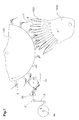
- Fig. 1 shows a schematic representation Transport device 10 according to the invention by a Feed conveyor or a first conveyor 2 supplementary products 1 are supplied by the transport device 10 at a reception point A1 Holding members 20a, ..., 20d detected and after transport at a delivery point A2 of a transport clamp 6 second conveyor 100 (see FIGS. 6 and 7) become.
- the second conveyor shown here, for example 100 and the transport brackets 6 are in the patent EP 0 675 062 B1 described in detail.
- Fig. 7 the supplementary products 1 directly form the band or strip material 3 ', which is from a spindle 4a unwound and fed to a cutting device 90 which supplementary products 1 of the strip material 3 ' separates and feeds the transport device 10.
- the directions of conveyance of the first and second conveyors 2, 100 and the transport device 10 according to the invention lie on one level.
- the required Change of location of the supplementary products 1 takes place as described in detail below, by rotation the holding members 20a, ..., 20d.
- the first conveyor 2, the direction of conveyance with F1 is used to supply supplementary products 1 on a carrier tape 3 by means of a Adhesive layer 1c are attached.
- the adhesive layer 1c is in Form of a strip running in the conveying direction F1 on left side margin of the supplementary products 1 provided.
- the Carrier tape 3 is by means of a spindle 4a stored stock roll unwound and around pulleys 4b, 4c and 4d led to the receiving point Al.
- the carrier tape 3 is pointed Angle led around a release edge 5, so that the Supplementary products 1 are detached from the carrier tape 3 and continue in feed direction F1. That of the Supplementary products 1 freed carrier tape 3 is in a the direction F2 opposite to the feed direction F1 drawn and disposed of.
- the supplementary product supplied on the support element 7a 1 is gripped by the holding element 20a on its upper side la and with the bottom 1b and the exposed Adhesive layer lc directed radially outward about an axis x transported to the delivery point A2 and there on a released further support element 7b.
- the one driven in the direction of rotation around the first axis x Holding member 20a is also rotatable about a second axis y stored, which is at least approximately perpendicular to the first Axis x stands and with the holding member 20a around the first Axis x rotates.
- a second axis y stored, which is at least approximately perpendicular to the first Axis x stands and with the holding member 20a around the first Axis x rotates.
- the supplementary products 1 in the exemplary embodiment Turned 90 ° clockwise so that the on the Adhesive layer 1c of the edge of the supplementary products 1 at the delivery point A2 in relation to the conveying direction F3 of the second conveyor 100 runs on.
- Fig. 3 shows a preferred embodiment of the inventive Device 10 with associated drive and Control devices 12, 14, 15 in detail.
- Fig. 4 shows the Device according to the invention in a cross section along the section line IV-IV entered in Fig. 3.
- the transport device 10 four as Suction tools or suction devices designed holding members 20a, 20b, 20c and 20d, each in a bearing body 22 are rotatably mounted about an axis y, which is perpendicular to Axis x of the drive shaft 11 is.
- the bearing body 22 are with a rotor disk 28, optionally with Rotor arms, connected by means of a flange hub 25 on a shaft 11 aligned along the first axis x is attached. Through the bearing body 22 and the Flange-hub 25 connected rotor disk 28 is thus a formed by the shaft 11 driven rotor 27.
- the holding members 20a, 20b, 20c, 20d have one in the bearing body 22 by means of two bearings 23a and 23b rotatably supported, with an air duct 56 provided hollow shaft 21, the radially outward directed end with one for grasping products 1 suitable suction port 24 is provided and its counter the first axis x directed end into an ejector 55 is used pneumatically with a controllable Compressed air device 15 is connected and as a jet pump serves with suction.
- the compressed air device 15 consists of a rotary valve sitting on the shaft 11 53, each via a line 54 with an ejector 55 connected and rotatable in one by means of a bearing 52 Stator 51 is mounted such that the stator 51 Air is supplied and in the rotary valve 53 for each Holding member 20a, 20b, 20c, 20d an air channel is formed.
- the air pressure (vacuum) inside each hollow shaft 21 becomes depending on the position of the holding members 20a, 20b, 20c, 20d controlled, so that at the recording point A1 Supplementary product 1 sucked in and after transport the delivery point A2 is released again.
- Vacuum system can be used by the need the air is extracted from the corresponding channels.
- Control device 14 has for each of the holding members 20a, 20b, 20c, 20d one in the bearing body 22 slidably mounted slide 32 and a backdrop 40, the Surface by the slider 32 by means of a wheel 31 is scanned.
- the slide 32 has one Tooth profile 33, the form-fitting in a hollow shaft 21 engages provided spur gear. By a Shift of the slide 32 parallel to the first axis x is therefore a corresponding rotation of the Hollow shaft 21 and thus the holding member 20a, 20b, 20c, 20d causes.
- the slide 32 is moved in Dependency of the surface of the backdrop 40 through which thus the rotation of the holding members 20a, 20b, 20c, 20d in Dependency of the angle of rotation of the shaft 11 is fixed.
- the backdrop 40 is on a parallel to the plane of rotation of the rotor 27 arranged mounting plate 41 attached via at least one support element 42 (in FIG. 4 there are two Support elements 42a, 42b shown) with a support structure 18 is connected.
- the support structure 18 has Base element 82 on which the support element 42 (42a, 42b) and two support members 81a, 81b are attached, which with bearings 83a, 83b serving to support the shaft 11 are provided.
- a part of the Shaft drive 12 attached (see Fig. 3 and Fig. 4).
- the Transport clamps 6 is in the takeover section, at Delivery point A2 of the transport device 10, one each Supplementary product 1 at its, in the direction of rotation U seen, trailing edge detected and then, as in Fig. 7 shown, given to printed products 9, which in the Processing device 1000 astride wall elements 1001 are arranged.
- the transfer is subsequently based on FIGS. 8a to 8d a supplementary product 1 from the first to the second Conveyors 2, 100 by means of the transport device according to the invention 10 described.
- a supplementary product 1 detached and at the reception point A1 on the first Support element 7a is deposited (see Fig. 8a, item a).
- the next holding element 20a becomes the supplementary product placed on the support element 7a 1 held by the bolt 8 (see Fig. 8b, Pos. B).
- Fig. 8c item c
- Supplementary product 1 by folding down the latch 8 released (see Fig. 8d, item d).
- A2 is the registered supplementary product 1 by means of Control device 14 rotated so far about the second axis y until the edge of the Supplementary product 1 in relation to the direction of rotation of the Rotor 27 runs on (see Fig. 8c, item g).
- the holding member 20c has the delivery point in FIG. 8a, item e A2 reaches and then places the transported one Supplementary product 1 on the second support element 7b (see Fig. 8b, item f and 8c, item g). After dropping of the supplementary product 1, this is by the holding member 20c released (see Fig. 8d, item h), so that it, like in Figures 8a-8c, positions i, j and k shown by a transport clamp 6 is grasped and carried away can.
- FIGS. 9a to 9d show further methods of supply and preparation of supplementary products 1 shown for example, as shown in Fig. 7, with printed matter 9 are connected.
- Carrier tape 3 for the supplementary products 1 is shown in Fig. 9a and 9b uses a band 3 'which has an in Conveying direction continuous adhesive layer 1c ' having.
- the tape 3 ' is in front of the recording point a cutting device 90 in supplementary products 1 ' divided, which after the transport process with Printed products 9, i.e. the Pass through the transport device 10 without turning.
- Fig. 9c and Fig. 9d one is not with an adhesive layer provided band 3 "shown by the cutter 90 is broken down into parts according to the Coating by means of adhesive dispensers 91, 92 and / or labeling by means of a print head 93 (e.g. ink jet) form the supplementary products 1 ".
- the parts can e.g. Samples of goods or sample bags that form a ribbon 3 "are joined together.
- Fig. 9d it can also be seen that for assembly printed products provided with supplementary products 1 9 in processing facilities 1000 different can be stored. Since the transport device according to the invention 10 the supplementary products 1 for each type to store a printed product in the required Delivering the situation, it is not only regarding spatial relationships, but also functional versatile. Supplementary products 1 can be found in rotated at any angle around the second axis y and be connected to the printed matter 9, the inserted in slots, astride on Wall elements or placed on a conveyor belt in the Processing device 1000 are stored.
- the required change in position of the supplementary products 1 during the passage of the transport device 10, i.e. the Rotation about the second axis y in a desired Angle and direction of rotation is determined by the shape of the backdrop 40 determined.
- Supplementary products 1 without turning can pass through the transport device 10 for example - as shown in Fig. 3a - the backdrop 40 from that indicated by dash-dotted lines in FIG. 3a Position in the direction of the first axis x in the full Line drawn position in which they are adjusted with the wheels 31 outside the area of engagement located so that the Complementary products 1 from the reception point A1 to the Delivery point A2 does not rotate around the second axis y takes place.
- the backdrop 40 can also in one Intermediate position between the two in Fig. 3a Limit positions shown (dash-dotted - maximum Twisting, e.g. 90 ° full line - no twisting) are held, creating the desired angle of rotation for the Supplementary products 1 is reduced.
- the mounting plate 41 connected to the backdrop 40 a support element 42 'attached to the shaft 11 on the one hand and on a parallel to the shaft 11
- Guide rod 96 is slidably arranged on the other hand.
- the guide rod 96 is connected to the base element 82 connected supporting elements 81b, 81c.
- Mounting plate 41 is a control cylinder 97 between the Mounting plate 41 and the support member 81b arranged.
- Control variant can with the backdrop 40 via the Wheel 31 cooperating slider 32 by means of itself known pawl 98 in a particular one certain angle of rotation of the holding member 20 corresponding Position are blocked and remain in this, too when the wheel 31 is out of engagement with the link 40 reached.
- a control element 99 By means of a control element 99, the Pawl 98 in a dash-dotted line in Fig. 5a position shown are adjusted, and thereby the Blockage caused by a pinch between an opening 98 'of the pawl 98 and the slide circumference, To get picked up.
- This is a selectable individual Turning or not turning by means of the control element 99 enables. It is also conceivable to set the backdrop 40 on the Mounting plate 41 to rotate the shaft 11 such that the active area of the backdrop 40 outside the Funding area.
- Transport device 10 with less or more than the four shown holding members 20a, ..., 20d.
- the Number of holding members 20 is preferably below Taking into account the size of the supplementary products 1 chosen.
- the supplementary products 1 in its upper area captured on its underside and with this also released on the support element 7b, previously (For example, by turning the 20b Holding member) a twisting of the supplementary products 1 in a desired angle of rotation can take place.
- the transport device 10 can of course be used also for the transport of supplementary products 1 used at the reception point in stacked form.
- a single supplement 1 can be of an auxiliary tool, an additional Suction cup or a cutting knife, raised or by a holding member 20a, 20b, 20c, 20d can be detected directly.
- the supplementary products 1, 1 ', 1 " can therefore by arbitrary first conveyor devices 2, 2 ', 2' 'fed and prepared by the transport device according to the invention 10 transported and in a required Positioned and by any second and others Conveyors 100, 1000 are processed further.
- supplementary products that do not have an adhesive layer can be provided by the transport device according to the invention 10 advantageously transported and in a desired location.
- the supplementary products are preferably lighter printed products, for example Notes in the manner of "Post-it” ® products, with samples or information documents provided with content, to connect with the print products are.
- the transport device 10 is also used the first and second conveyors 2; 100 preferably synchronized in such a way that a smooth transfer of the Supplementary products 1 is possible.
- transport device 10 the transported supplementary products 1 at the delivery point A2 directly to printed products or attaching other products.
- Supplementary products 1 can also be transported that are not coated with adhesive, and in Printed products or other products inserted (e.g. an advertising letter in a daily newspaper).
Landscapes
- Engineering & Computer Science (AREA)
- Mechanical Engineering (AREA)
- Discharge By Other Means (AREA)
- Specific Conveyance Elements (AREA)
- Making Paper Articles (AREA)
- Feeding Of Articles By Means Other Than Belts Or Rollers (AREA)
- Auxiliary Devices For And Details Of Packaging Control (AREA)
- Supplying Of Containers To The Packaging Station (AREA)
- Chain Conveyers (AREA)
Abstract
Description
Die Erfindung betrifft eine Vorrichtung und ein Verfahren
zum Transport von insbesondere mit Haftmittel versehenen
flächigen Ergänzungsprodukten von einer Aufnahmestelle zu
einer Abgabestelle gemäss dem Oberbegriff von Anspruch 1
bzw. 16.The invention relates to an apparatus and a method
for the transport of, in particular, adhesives
flat supplementary products from a reception center
a delivery point according to the preamble of
Bei der Verarbeitung, insbesondere beim Sammeln von Druckereierzeugnissen, sind oft Ergänzungsprodukte, wie Etiketten, Warenmuster oder "post-it"®-Produkte in den oder auf die Druckereierzeugnisse anzubringen. Die Ergänzungsprodukte können beispielsweise gestapelt vorliegen oder von einem in Rollenform vorliegenden Streifen oder Band abgetrennt werden. Dieses Band kann ein Trägerband sein, auf dem die Ergänzungsprodukte anhaften, während des Fördervorgangs von jenem abgelöst, durch eine gattungsgemässe Vorrichtung erfasst und zum Abgabeort transportiert und anschliessend direkt, gegebenenfalls auch durch ein weiteres Werkzeug, mit den Druckereiprodukten verbunden werden. Der Streifen bzw. das Band kann jedoch auch Grundlage der Ergänzungsprodukte bilden, die vom Streifen abgetrennt und gegebenenfalls noch weiter bearbeitet, gegebenenfalls mit einem Haftmittel versehen werden.When processing, especially when collecting Printed products are often complementary products, such as Labels, samples or "post-it" ® products in the or affixed to the printed matter. The Supplementary products can be stacked, for example or from a roll Strip or tape can be separated. This tape can be a Be a carrier tape on which the supplementary products adhere, detached from that during the funding process, by a Generic device detected and to the delivery location transported and then directly, if necessary also by another tool with which Printing products. The strip or that However, tape can also be the basis of complementary products form, separated from the strip and, if necessary further processed, if necessary with a Adhesives are provided.
Sofern für die zugeführten Ergänzungsprodukte eine Haftschicht benötigt wird, ist diese in bezug auf die Förderrichtung normalerweise seitlich in Form eines Streifens an den Ergänzungsprodukten vorgesehen. Das Auftragen eines in Längsrichtung durchgehend verlaufenden Haftstreifens auf ein Band ist nämlich wesentlich einfacher als das abschnittweise Auftragen von Querstreifen, die zudem ,mit einem Abtrennwerkzeug zu synchronisieren sind. Auch bei der Verwendung eines Trägerbandes sind die darauf anhaftenden Ergänzungsprodukte vorzugsweise in Förderrichtung seitlich mit einer einen Streifen bildenden Haftschicht versehen. Sobald das Trägerband z.B. um eine einen spitzen Winkel bildende Ablösekante geführt wird, verlaufen die mit einem Haftmittel beschichteten Ergänzungsprodukte unter Ablösung vom Trägerband weiter in Förderrichtung.If a for the supplementary products supplied Adhesive layer is needed, this is in relation to the Direction of conveyance normally in the form of a Stripe provided on the supplementary products. The Apply a continuous one in the longitudinal direction Adhesive tape on a tape is much easier than the application of horizontal stripes in sections, which also to synchronize with a detaching tool are. Even when using a carrier tape are the supplementary products adhering to it preferably in Direction of conveyance laterally with a strip forming Provide adhesive layer. As soon as the carrier tape e.g. by one leading edge forming an acute angle, run the coated with an adhesive Supplementary products detached from the carrier tape continue in Direction of conveyance.
Während das Zuführen von seitlich mit einem Haftstreifen versehenen Ergänzungsprodukten vorteilhaft ist, können seitlich mit einem Haftstreifen versehene Ergänzungsprodukte nur mit entsprechendem Aufwand korrekt mit Druckereierzeugnissen verbunden werden. Oft werden daher Vorrichtungen verwendet, bei denen innerhalb des Fördervorgangs ein Wechsel der Transportrichtung der Ergänzungsprodukte erfolgt, so dass die an den Haftstreifen anliegende Kante nach dem Wechsel in bezug auf die neue Transportrichtung nachläuft.While feeding from the side with an adhesive tape Supplementary products provided can be advantageous Supplementary products with adhesive strips on the side only with appropriate effort Printed products. Often, therefore Devices used in the conveying process a change in the direction of transport of the supplementary products done so the attached to the adhesive strips adjacent edge after changing with respect to the new one Direction of transport continues.
Aus der Offenlegungsschrift WO 99/06285 ist eine derartige Vorrichtung bekannt. Darin ist ein Zuführförderer gezeigt, durch den ein seitlich mit einem Haftschichtstreifen versehenes Band einer Schneidvorrichtung zugeführt wird, welche Ergänzungsprodukte von diesem Band abtrennt. Die abgetrennten Ergänzungsprodukte werden mittels eines Saugwerkzeugs oder einer Walze einem Rotor zugeführt, der diese mittels Greif- oder Saugelementen in bezug auf die Zuführ- bzw. Bandlängsrichtung seitlich erfasst, zu einer Abgabestelle führt und dort mit einem Druckereierzeugnis verbindet und frei gibt. Die Förderrichtung der Ergänzungsprodukte auf dem Zuführförderer steht dabei senkrecht zur Ebene, in der die seitlich erfassten Ergänzungsprodukte vom Rotor transportiert werden und in der auch die zu bestückenden Druckereierzeugnisse tangential am Rotor vorbei geführt werden.Such is known from the published patent application WO 99/06285 Device known. It shows a feed conveyor through the one on the side with an adhesive layer strip provided tape is fed to a cutting device, which supplementary products separate from this volume. The separated supplementary products are by means of a Suction tool or a roller fed to a rotor, the this by means of gripping or suction elements in relation to the Feed or strip longitudinal direction recorded laterally, to a Delivery point leads and there with a printed product connects and releases. The funding direction of the Complementary products are on the feed conveyor perpendicular to the plane in which the laterally captured Complementary products are transported by the rotor and in which also includes the printed products to be loaded are guided tangentially past the rotor.
Die Ergänzungsprodukte, die in Bezug auf Zuführförderrichtung seitlich mit einer einen Streifen bildenden Haftschicht versehen sind, werden daher derart vom Rotor erfasst, dass die an den Haftschichtstreifen anliegende Kante des Ergänzungsproduktes in bezug auf die Umlaufrichtung des Rotors nachläuft.The supplementary products related to feed direction laterally with a stripe Are provided by the rotor detected that the applied to the adhesive layer strips Edge of the supplementary product in relation to the direction of rotation of the rotor runs on.
Die in der WO 99/06285 gezeigte gegenseitige Ausrichtung
des Zuführförderers für die Ergänzungsprodukte, des Rotors
und des Förderers für die Druckereierzeugnisse bedingt
jedoch einen hohen Platzbedarf.The mutual alignment shown in
Aufgrund der Änderung der Transportrichtung innerhalb des Fördervorgangs müssen die einzelnen Transportsequenzen zudem mit hoher Präzision durchgeführt werden, weshalb sich eine Steigerung der Tranportkadenz dieser Vorrichtung nur mit hohem Aufwand realisieren lässt.Due to the change in the transport direction within the Funding process must the individual transport sequences can also be carried out with high precision, which is why there is an increase in the transport cadence of this device can only be realized with great effort.
Der vorliegenden Erfindung liegt daher die Aufgabe zugrunde, eine leistungsfähige, universell einsetzbare Vorrichtung zu schaffen und ein Verfahren anzugeben, durch die von einem ersten Förderer in einer ersten Lage zugeführte Ergänzungsprodukte erfasst, zu einem zweiten Förderer transportiert und dort in einer für die Weiterverarbeitung geeigneten zweiten Lage abgegeben werden können. The present invention is therefore based on the object based on a powerful, universally applicable To create device and specify a method by by a first sponsor in a first location supplied supplementary products recorded, to a second Transported and there in one for the conveyor Submitted further processing suitable second layer can be.
Diese Aufgabe wird mit einer Vorrichtung bzw. einem
Verfahren mit den Merkmalen des Anspruches 1 bzw. 16
gelöst.This task is accomplished with a device or a
16. The method with the features of
Die erfindungsgemässe Vorrichtung, die für den Transport von Ergänzungsprodukten, insbesondere mit Haftmittel versehenen Druckereiprodukten, von einer bei einem ersten Förderer vorgesehenen Aufnahmestelle zu einer bei einem zweiten Förderer vorgesehenen Abgabestelle bestimmt ist, ist universell einsetzbar, da die Förderrichtungen des ersten und des zweiten Förderers beliebig wählbar sind. Anhand der erfindungsgemässen Transportvorrichtung erfolgt dabei die für die Abgabe an den zweiten Förderer erforderliche Lageänderung der Ergänzungsprodukte.The inventive device for transportation of supplementary products, especially with adhesive provided printing products, from one at a first The admission point provided for one at a second conveyor intended delivery point is determined, is universally applicable because the conveying directions of the first and second conveyors are arbitrary. Using the transport device according to the invention doing so for delivery to the second sponsor required change of position of the supplementary products.
In einer vorzugsweisen Ausgestaltung der Erfindung liegen die Förderrichtung des ersten und des zweiten Förderers sowie der erfindungsgemässen Transportvorrichtung in einer Ebene, so dass der Platzbedarf neben dem für die Druckereierzeugnissen vorgesehenen Förderer minimal ist.In a preferred embodiment of the invention the direction of conveyance of the first and second conveyors and the transport device according to the invention in one Level, so the space requirement next to that for the Printed conveyor is minimal.
Da der gesamte Fördervorgang erfindungsgemäss in einer Förderrichtung oder zumindest innerhalb einer Ebene mit leicht handhabbaren Übergängen zwischen den einzelnen Fördervorrichtungen erfolgen kann, lassen sich zudem hohe Transportkadenzen mit geringem Aufwand realisieren.Since the entire conveying process according to the invention in one Direction of funding or at least within one level easily manageable transitions between the individual Conveyors can take place, can also be high Realize transport cadences with little effort.
Die Erfindung wird nachfolgend anhand von Ausführungsbeispielen unter Bezugnahme auf die Zeichnung näher erläutert. Dabei zeigen :
- Fig. 1
- in perspektivischer Darstellung eine erfindungsgemässe Transportvorrichtung, der von einem ersten Förderer Ergänzungsprodukte zugeführt werden, die nach dem Transport und gegebenenfalls einer Lageänderung von einer Transportklammer eines zweiten Förderers erfasst werden;
- Fig. 2
- in Seitenansicht die Transportklammer von Fig. 1 beim Erfassen eines Ergänzungsproduktes;
- Fig. 3
- in Ansicht und teilweise geschnitten eine erfindungsgemässe Transportvorrichtung mit Antriebs- und Steuereinrichtungen;
- Fig. 3a
- eine der Fig. 3 entsprechende Darstellung mit einer zweiten Variante einer Steuereinrichtung;
- Fig. 4
- in Seitenansicht die erfindungsgemässe Transportvorrichtung teilweise geschnitten entlang der in Fig. 3 eingetragenen Schnittlinie IV-IV;
- Fig. 5
- die erfindungsgemässe Transportvorrichtung in einem Schnitt entlang der in Fig. 3 eingetragenen Schnittlinie V-V;
- Fig. 5a
- eine der Fig. 5 entsprechende Darstellung mit einer dritten Variante einer Steuereinrichtung;
- Fig. 6
- eine erfindungsgemässe Transportvorrichtung, die Ergänzungsprodukte von einem ersten Förderer übernimmt und an einen zweiten Förderer abgibt;
- Fig. 6a
- eine der Fig. 6 entsprechende Darstellung mit einer zweiten Variante des ersten Förderers;
- Fig. 6b
- eine der Fig. 6 entsprechende Darstellung mit einer dritten Variante des ersten Förderers;
- Fig. 7
- die Transportvorrichtung von Fig. 6 in Zusammenarbeit mit einer Verarbeitungseinrichtung, in der mit Ergänzungsprodukten zu bestückende Druckereiprodukte angeordnet sind;
- Fig. 8a-d
- die Transportvorrichtung von Fig. 6 während verschiedenen Phasen beim Transport von Ergänzungsprodukten und
- Fig. 9a-d
- die Vorbereitung von Ergänzunsprodukten sowie deren Anordnung nach deren Verbindung mit einem in der Verarbeitungseinrichtung abgelegten Druckereierzeugnis.
- Fig. 1
- a perspective view of a transport device according to the invention, the supplementary products are supplied by a first conveyor, which are captured by a transport bracket of a second conveyor after transport and, if necessary, a change of position;
- Fig. 2
- in side view the transport bracket of Figure 1 when capturing a supplementary product.
- Fig. 3
- in view and partially sectioned a transport device according to the invention with drive and control devices;
- Fig. 3a
- a representation corresponding to Figure 3 with a second variant of a control device.
- Fig. 4
- a side view of the transport device according to the invention, partially cut along the section line IV-IV shown in FIG. 3;
- Fig. 5
- the transport device according to the invention in a section along the section line VV entered in Figure 3;
- Fig. 5a
- a representation corresponding to FIG. 5 with a third variant of a control device;
- Fig. 6
- a transport device according to the invention which accepts supplementary products from a first conveyor and delivers them to a second conveyor;
- Fig. 6a
- a representation corresponding to FIG. 6 with a second variant of the first conveyor;
- Fig. 6b
- a representation corresponding to FIG. 6 with a third variant of the first conveyor;
- Fig. 7
- 6 in cooperation with a processing device, in which printed products to be equipped with supplementary products are arranged;
- 8a-d
- the transport device of Fig. 6 during different phases in the transport of supplementary products and
- 9a-d
- the preparation of supplementary products and their arrangement after their connection to a printed product stored in the processing device.
Fig. 1 zeigt in schematischer Darstellung eine
erfindungsgemässe Transportvorrichtung 10, der von einem
Zuführförderer bzw. einem ersten Förderer 2 Ergänzungsprodukte
1 zugeführt werden, die von der Transportvorrichtung
10 an einer Aufnahmestelle A1 durch
Halteorgane 20a, ..., 20d erfasst und nach dem Transport
an einer Abgabestelle A2 einer Transportklammer 6 eines
zweiten Förderers 100 (siehe Fig. 6 und Fig. 7) zugeführt
werden. Der hier beispielsweise gezeigte zweite Förderer
100 und die Transportklammern 6 sind in der Patentschrift
EP 0 675 062 Bl im Detail beschrieben.Fig. 1 shows a schematic
In Fig. 7 bilden die Ergänzungsprodukte 1 direkt das Band
bzw. Streifenmaterial 3', das von einer Spindel 4a
abgewickelt und einer Schneideinrichtung 90 zugeführt
wird, welche Ergänzungsprodukte 1 vom Streifenmaterial 3'
abtrennt und der Transportvorrichtung 10 zuführt. In Fig. 7 the
Die Förderrichtungen des ersten und des zweiten Förderers
2, 100 und der erfindungsgemässen Transportvorrichtung 10
liegen dabei in einer Ebene. Die erforderliche
Lageänderung der Ergänzungsprodukte 1 erfolgt, wie
nachstehend noch im Detail beschrieben, durch eine Drehung
der Halteorgane 20a, ..., 20d.The directions of conveyance of the first and
Der erste Förderer 2, dessen Förderrichtung mit F1
bezeichnet ist, dient zur Zulieferung von Ergänzungsprodukten
1, die auf einem Trägerband 3 mittels einer
Haftschicht 1c befestigt sind. Die Haftschicht 1c ist in
Form eines in Förderrichtung F1 verlaufenden Streifens am
linken Seitenrand der Ergänzungsprodukte 1 vorgesehen. Das
Trägerband 3 wird von einer mittels einer Spindel 4a
gelagerten Vorratsrolle abgewickelt und um Umlenkrollen
4b, 4c und 4d zur Aufnahmestelle Al geführt. Bei der
Aufnahmestelle A1 wird das Trägerband 3 in einem spitzen
Winkel um eine Ablösekante 5 geführt, so dass die
Ergänzungsprodukte 1 vom Trägerband 3 abgelöst werden und
weiter in Zuführrichtung F1 verlaufen. Das von den
Ergänzungsprodukten 1 befreite Trägerband 3 wird in einer
der Zuführrichtung F1 entgegengesetzten Richtung F2
gezogen und entsorgt.The
Mit einem auf die Transportgeschwindigkeit der
Transportvorrichtung 10 abgestimmten Zuführvorschub der
Ergänzungsprodukte 1, können diese dynamisch, d.h. ohne
Geschwindigkeitsreduktion und Zwischenlagerung, präzise an
die Halteorgane 20a, 20b, ... der Transportvorrichtung 10
übergeben werden. Analog dazu wird vorzugsweise auch die
Fördergeschwindigkeit des zweiten Förderers 100 an die
Transportgeschwindigkeit der Transportvorrichtung 10
angepasst. Dadurch erfolgt eine praktisch unverzögerte,
fliessende Übergabe der Ergänzungsprodukte 1 zwischen den
einzelnen Vorrichtungen.With one on the transport speed of the
Aus Fig. 6 ist zudem ersichtlich, dass die Ergänzungsprodukte
1 vor dem Erfassen durch das Halteorgan 20a auf
einem Auflageelement 7a zwischengelagert und durch einen
Riegel 8 gehalten werden, der das entsprechende
Ergänzungsprodukt 1 freigibt, nachdem es durch das
Halteorgan 20a erfasst wurde (siehe Fig. 8d). Die auf dem
Ergänzungsprodukt 1 verbleibende Haftschicht 1c befindet
sich auf der Unterseite 1b des auf dem Auflageelement 7a
aufliegenden Ergänzungsproduktes 1.6 also shows that the
Das auf dem Auflageelement 7a zugeführte Ergänzungsprodukt
1 wird vom Halteelement 20a an dessen Oberseite la erfasst
und mit der Unterseite 1b und der frei liegenden
Haftschicht lc radial nach aussen gerichtet um eine Achse
x zur Abgabestelle A2 transportiert und dort auf einem
weiteren Auflageelement 7b freigegeben.The supplementary product supplied on the
Das in Umlaufrichtung um die erste Achse x angetriebene
Halteorgan 20a ist zudem um eine zweite Achse y drehbar
gelagert, die zumindest annähernd senkrecht zur ersten
Achse x steht und mit dem Halteorgan 20a um die erste
Achse x rotiert. Während des Transports von der
Aufnahmestelle A1 zur Abgabestelle A2 erfolgt eine Drehung
des Ergänzungsproduktes 1 um die Achse y, so dass dieses
in der zur Weiterverarbeitung benötigten Lage an der
Abgabestelle A2 an eine Transportklammer 6 des zweiten
Förderers 100 abgegeben werden kann. Im vorliegende
Ausführungsbeispiel werden die Ergänzungsprodukte 1 im
Uhrzeigersinn um 90° gedreht, so dass die an der
Haftschicht 1c anliegende Kante der Ergänzungsprodukte 1
an der Abgabestelle A2 in Bezug auf die Förderrichtung F3
des zweiten Förderers 100 nachläuft.The one driven in the direction of rotation around the first axis
Aus Fig. 1 und Fig. 2 ist ersichtlich, dass die
Transportklammer 6 das Ergänzungsprodukt 1 an der
nachlaufenden Kante erfasst und, wie in Fig. 6 und 7
gezeigt, einer Verarbeitungseinrichtung 1000 bzw. darin
gelagerten Druckereierzeugnissen 9 zuführt.From Fig. 1 and Fig. 2 it can be seen that the
Fig. 3 zeigt eine vorzugsweise Ausgestaltung der erfindungsgemässen
Vorrichtung 10 mit zugehörigen Antriebs- und
Steuereinrichtungen 12, 14, 15 im Detail. Fig. 4 zeigt die
erfindungsgemässe Vorrichtung in einem Querschnitt längs
der in Fig. 3 eingetragenen Schnittlinie IV-IV. Daraus ist
ersichtlich, dass die Transportvorrichtung 10 vier als
Saugwerkzeuge bzw. Sauger ausgestaltete Halteorgane 20a,
20b, 20c und 20d aufweist, die je in einem Lagerkörper 22
um eine Achse y drehbar gelagert sind, die senkrecht zur
Achse x der Antriebswelle 11 steht. Die Lagerkörper 22
sind mit einer Rotorscheibe 28, gegebenenfalls mit
Rotorarmen, verbunden, die mittels einer Flansch-Nabe 25
auf einer längs der ersten Achse x ausgerichteten Welle 11
befestigt ist. Durch die Lagerkörper 22 und die mit der
Flansch-Nabe 25 verbundene Rotorscheibe 28 wird somit ein
von der Welle 11 angetriebener Rotor 27 gebildet.Fig. 3 shows a preferred embodiment of the
Die als Sauger ausgestalteten Halteorgane 20a, 20b, 20c,
20d weisen einen im Lagerkörper 22 mittels zwei Lagern 23a
und 23b drehbar gelagerten, mit einem Luftkanal 56
versehenen Hohlschaft 21 auf, dessen radial nach aussen
gerichtetes Ende mit einem zum Erfassen von Erzeugnissen 1
geeigneten Sauganschluss 24 versehen ist und dessen gegen
die erste Achse x gerichtetes Ende in einen Ejector 55
eingesetzt ist, der pneumatisch mit einer steuerbaren
Druckluftvorrichtung 15 verbunden ist und als Strahlpumpe
mit Absaugwirkung dient. Die Druckluftvorrichtung 15
besteht aus einem auf der Welle 11 sitzenden Drehventil
53, das je über eine Leitung 54 mit je einem Ejector 55
verbunden und mittels einem Lager 52 drehbar in einem
Stator 51 derart gelagert ist, dass im Stator 51 die
Luftzufuhr erfolgt und im Drehventil 53 für jedes
Halteorgan 20a, 20b, 20c, 20d ein Luftkanal gebildet wird.
Der Luftdruck (Vakuum) innerhalb jedes Hohlschafts 21 wird
dabei in Abhängigkeit der Lage der Halteorgane 20a, 20b,
20c, 20d gesteuert, so dass an der Aufnahmestelle A1 ein
Ergänzungsprodukt 1 angesaugt und nach dem Transport an
der Abgabestelle A2 wieder freigegeben wird. Anstelle der
beschriebenen Druckluftvorrichtung, mittels der durch
Erhöhung der Strömungsgeschwindigkeit in den Ejectoren 55
die notwendige Saugwirkung erzeugt wird, kann auch ein
Unterdrucksystem verwendet werden, durch das bedarfsweise
die Luft aus den entsprechenden Kanälen abgesaugt wird.The holding
Fig. 5 zeigt die erfindungsgemässe Transportvorrichtung in
einem Schnitt entlang der in Fig. 3 eingetragenen
Schnittlinie V-V. Die darin im Detail gezeigte
Steuereinrichtung 14 weist für jedes der Halteorgane 20a,
20b, 20c, 20d einen in deren Lagerkörper 22 verschiebbar
gelagerten Schieber 32 sowie eine Kulisse 40 auf, deren
Oberfläche durch den Schieber 32 mittels einem Rad 31
abgetastet wird. Der Schieber 32 weist dabei ein
Zahnprofil 33 auf, das formschlüssig in eine am Hohlschaft
21 vorgesehene Stirnverzahnung eingreift. Durch eine
Verschiebung des Schieber 32 parallel zur ersten Achse x
wird daher eine dazu korrespondierende Drehung des
Hohlschafts 21 und somit des Halteorgans 20a, 20b, 20c,
20d bewirkt. Die Verschiebung des Schiebers 32 erfolgt in
Abhängigkeit der Oberfläche der Kulisse 40, durch die
somit die Drehung der Halteorgane 20a, 20b, 20c, 20d in
Abhängigkeit des Drehwinkels der Welle 11 festgelegt ist.
Die Kulisse 40 ist an einer parallel zur Rotationsebene
des Rotors 27 angeordneten Montageplatte 41 befestigt, die
über mindestens ein Tragelement 42 (in Fig. 4 sind zwei
Tragelemente 42a, 42b gezeigt) mit einer Tragkonstruktion
18 verbunden ist. Die Tragkonstruktion 18 weist ein
Basiselement 82 auf, an dem das Tragelement 42 (42a, 42b)
und zwei Stützelemente 81a, 81b befestigt sind, die mit
zur Lagerung der Welle 11 dienenden Lagern 83a, 83b
versehen sind. Am Stützelement 81b ist zudem ein Teil des
Wellenantriebs 12 befestigt (siehe Fig. 3 und Fig. 4).5 shows the transport device according to the invention in
a section along the entered in Fig. 3
Section line V-V. The one shown in
Der in Fig. 6 gezeigte zweite Förderer 100, der wie
erwähnt in der Patentschrift EP 0 675 062 B1 im Detail
beschrieben ist, weist hintereinander angeordnete, in
Umlaufrichtung U angetriebene, individuell steuerbare
Transportklammern 6 auf, die mit je zwei Klemmelementen
686, 688 versehen sind, die in einem Übernahmeabschnitt
der Umlaufbahn ein wenigstens annähernd in Umlaufrichtung
U gerichtetes Klammermaul 614 bilden. Durch jede der
Transportklammern 6 wird im Übernahmeabschnitt, bei der
Abgabestelle A2 der Transportvorrichtung 10, jeweils ein
Ergänzungsprodukt 1 bei dessen, in Umlaufrichtung U
gesehen, nachlaufender Kante erfasst und dann, wie in Fig.
7 gezeigt, an Druckereierzeugnisse 9 abgegeben, die in der
Verarbeitungseinrichung 1000 rittlings auf Wandelementen
1001 angeordnet sind.The
Anhand der Figuren 8a bis 8d wird nachfolgend die Übergabe
eines Ergänzungsproduktes 1 vom ersten zum zweiten
Förderer 2, 100 mittels der erfindungsgemässen Transportvorrichtung
10 beschrieben. The transfer is subsequently based on FIGS. 8a to 8d
a
Ein mit Ergänzungsprodukten 1 versehenes Trägerband 3
wird, wie oben beschrieben, in einem spitzen Winkel um
eine Ablösekante 5 geführt, so dass ein Ergänzungsprodukt
1 abgelöst und an der Aufnahmestelle A1 auf dem ersten
Auflageelement 7a abgelegt wird (siehe Fig. 8a, Pos. a).
Bis zur Aufnahme durch das nächstfolgende Halteorgan 20a
wird das auf dem Auflageelement 7a abgelegte Ergänzungsprodukt
1 durch den Riegel 8 gehalten (siehe Fig. 8b,
Pos. b). Nach dem Erfassen des Ergänzungsproduktes 1 durch
das Halteorgan 20a (siehe Fig. 8c, Pos. c) wird das
Ergänzungsprodukt 1 durch Herunterklappen des Riegels 8
freigegeben (siehe Fig. 8d, Pos. d).A
Während des Transports zwischen Aufnahme- und Abgabestelle
A1; A2 wird das erfasste Ergänzungsprodukt 1 mittels der
Steuereinrichtung 14 soweit um die zweite Achse y gedreht,
bis der mit der Haftschicht 1c versehene Rand des
Ergänzungsproduktes 1 in bezug auf die Drehrichtung des
Rotors 27 nachläuft (siehe Fig. 8c, Pos. g).During transport between pick-up and drop-off point
A1; A2 is the registered
Das Halteorgan 20c hat in Fig. 8a, Pos. e die Abgabestelle
A2 erreicht und legt anschliessend das transportierte
Ergänzungsprodukt 1 auf dem zweiten Auflageelement 7b ab
(siehe Fig. 8b, Pos. f und 8c, Pos. g). Nach dem Ablegen
des Ergänzungsproduktes 1 wird dieses durch das Halteorgan
20c freigegeben (siehe Fig. 8d, Pos. h), so dass es, wie
in den Figuren 8a-8c, Positionen i, j und k gezeigt, durch
eine Transportklammer 6 erfasst und weggeführt werden
kann.The holding
In den Figuren 9a bis 9d sind weitere Methoden zur Zufuhr
und Vorbereitung von Ergänzungsprodukten 1 gezeigt, die
beispielsweise wie in Fig. 7 dargestellt, mit Druckereierzeugnissen
9 verbunden werden. Anstelle eines
Trägerbandes 3 für die Ergänzungsprodukte 1 wird in Fig.
9a und 9b ein Band 3' verwendet, das an einem Rand eine in
Förderrichtung durchgehend verlaufende Haftschicht 1c'
aufweist. Das Band 3' wird vor der Aufnahmestelle durch
eine Schneidvorrichtung 90 in Ergänzungsprodukte 1'
aufgeteilt, welche nach dem Transportvorgang mit
Druckereierzeugnissen 9 verbunden werden, d.h. die
Transportvorrichtung 10 ohne Drehen durchlaufen.FIGS. 9a to 9d show further methods of supply
and preparation of
In Fig. 9b ist gezeigt, dass die Ergänzungsprodukte 1'
während dem Transportvorgang mittels der
erfindungsgemässen Transportvorrichtung 10 in eine
gewünschte Lage gedreht werden.9b shows that the supplementary products 1 '
during the transport process using the
In Fig. 9c und Fig. 9d ist ein nicht mit einer Haftschicht
versehenes Band 3" gezeigt, das durch die Schneidvorrichtung
90 in Teile zerlegt wird, die nach der
Beschichtung mittels Haftmittelspendern 91, 92 und/oder
einer Beschriftung mittels eines Druckkopfs 93 (z.B. Ink-Jet)
die Ergänzungsprodukte 1" bilden. Die Teile können
z.B. Warenproben oder Musterbeutel sein, die zu einem Band
3" zusammengefügt sind.In Fig. 9c and Fig. 9d one is not with an adhesive layer
provided
Aus Fig. 9d ist ferner ersichtlich, dass zur Bestückung
mit Ergänzungsprodukten 1 vorgesehene Druckereierzeugnisse
9 in Verarbeitungseinrichtungen 1000 verschiedenartig
gelagert werden können. Da die erfindungsgemässe Transportvorrichtung
10 die Ergänzungsprodukte 1 für jede Art
ein Druckereierzeugnis zu lagern in der erforderlichen
Lage anliefern kann, ist sie nicht nur bezüglich
räumlichen Verhältnissen, sondern auch funktional
vielseitig einsetzbar. Ergänzungsprodukte 1 können in
einem beliebigen Winkel um die zweite Achse y gedreht und
mit den Druckereierzeugnissen 9 verbunden werden, die
eingesteckt in Aufnahmespalten, rittlings gesammelt auf
Wandelementen oder abgelegt auf einem Förderband in der
Verarbeitungseinrichtung 1000 gelagert sind.From Fig. 9d it can also be seen that for assembly
printed products provided with
Die erforderliche Lageänderung der Ergänzungsprodukte 1
beim Durchlauf der Transportvorrichtung 10, d.h. die
Verdrehung um die zweite Achse y in einem gewünschten
Winkel und Drehrichtung, wird durch die Form der Kulisse
40 bestimmt. Sollen die Ergänzungsprodukte 1 ohne Drehen
die Transportvorrichtung 10 durchlaufen, so kann
beispielsweise - wie in Fig. 3a dargestellt - die Kulisse
40 aus der in Fig. 3a strichpunktiert angedeuteten
Stellung in Richtung der ersten Achse x in die mit voller
Linie gezeichnete Stellung verstellt werden, in der sie
sich ausserhalb des Eingriffsbereichs mit den Rädern 31
befindet, so dass während des Transports der
Ergänzungsprodukte 1 von der Aufnahmestelle A1 zu der
Abgabestelle A2 kein Drehen derselben um die zweite Achse
y erfolgt. Die Kulisse 40 kann aber auch in einer
Zwischenstellung zwischen den beiden in Fig. 3a
dargestellten Grenzstellungen (strichpunktiert - maximale
Verdrehung, z.B. 90,° volle Linie - keine Verdrehung)
gehalten werden, wodurch der gewünschte Drehwinkel für die
Ergänzungsprodukte 1 verkleinert wird.The required change in position of the
Bei dem in Fig. 3a dargestellten Ausführungsbeispiel ist
die mit der Kulisse 40 verbundene Montageplatte 41 an
einem Tragelement 42' angebracht, der auf der Welle 11
einerseits und auf einer zur Welle 11 parallelen
Führungsstange 96 anderseits verschiebbar angeordnet ist.
Die Führungsstange 96 wird von mit dem Basiselement 82
verbundenen Stützelementen 81b, 81c getragen. Zur
Verstellung der mit der Kulisse 40 versehenen
Montageplatte 41 ist ein Steuerzylinder 97 zwischen der
Montageplatte 41 und dem Stützelement 81b angeordnet.In the embodiment shown in Fig. 3a
the mounting
Bei einer weiteren, in Fig. 5a dargestellten
Steuerungsvariante kann der mit der Kulisse 40 über das
Rad 31 zusammenwirkende Schieber 32 mittels einer an sich
bekannten Sperrklinke 98 in einer bestimmten, einem
bestimmten Drehwinkel des Halteorgans 20 entsprechenden
Stellung blockiert werden und in dieser verbleiben, auch
wenn das Rad 31 ausser Eingriff mit der Kulisse 40
gelangt. Mittels eines Steuerungselementes 99 kann die
Sperrklinke 98 in eine in Fig. 5a strichpunktiert
dargestellte Stellung verstellt werden, und dadurch die
Blockierung, die durch ein Klemmen zwischen einer Öffnung
98' der Sperrklinke 98 und dem Schieberumfang erfolgt,
aufgehoben werden. Damit ist ein wählbares individuelles
Drehen oder Nichtdrehen mittels des Steuerungselementes 99
ermöglicht. Es ist auch denkbar, die Kulisse 40 auf der
Montageplatte 41 um die Welle 11 derart zu verdrehen, dass
der aktive Bereich der Kulisse 40 ausserhalb des
Förderbereiches liegt.In another, shown in Fig. 5a
Control variant can with the
Sowohl die Ausführung nach Fig. 3a als auch diejenige nach
Fig. 5a ermöglichen somit ein Ausschalten, Einschalten
oder Umschalten der Steuereinrichtung 14, so dass die
Ergänzungsprodukte 1 ohne Drehen oder mit Drehen, und zwar
in einem gewünschten, einstellbaren Winkel die
Transportvorrichtung 10 durchlaufen.3a as well as that according to FIG
5a thus enable switching off, switching on
or switching the
Im weiteren ist es selbstverständlich auch möglich, die
Transportvorrichtung 10 mit weniger oder mehr als den vier
gezeigten Halteorganen 20a, ..., 20d auszurüsten. Die
Anzahl der Halteorgane 20 wird vorzugsweise unter
Berücksichtigung der Grösse der Ergänzungsprodukte 1
gewählt.Furthermore, it is of course also possible that
Wie in Fig. 6a und 6b dargestellt können die als
Saugwerkzeuge ausgestalteten Halteorgane 20, die je in
einem Lagerkörper 22 um die Achse y drehbar gelagert sind,
statt dem aus Fig. 4 bekannten Rotor 27 einem
Umlaufförderer 127 mit einer in sich geschlossenen
Umlaufbahn zugeordnet werden. Auch hier wird die
Drehbewegung der die Ergänzungsprodukte 1
transportierenden Halteorgane 20 mittels einer nicht
dargestellten, ein- und ausschaltbaren bzw. umschaltbaren
Kulisse gesteuert.As shown in Fig. 6a and 6b, the as
Suction tools designed holding
Bei der in Fig. 6a dargestellten Anordnung des
Umlaufförderers 127 werden die Ergänzungsprodukte 1 in
seinem unteren Bereich auf ihrer Oberseite von den
Halteelementen 20 erfasst und dann durch den
Umlaufförderer 127 - ähnlich wie durch den Rotor 27 - mit
ihrer Unterseite nach oben umgelenkt. Das Drehen der
Ergänzungsprodukte 1 um die zur Umlaufbahn senkrechte
Achse y erfolgt bereits vor diesem Umlenken,
beispielsweise durch Drehen des mit 20a in Fig. 6a
bezeichneten Halteorgans.In the arrangement of the
Bei der in Fig. 6b dargestellten Anordnung des
Umlaufförderers 127 werden die Ergänzungsprodukte 1 in
seinem oberen Bereich auf ihrer Unterseite erfasst und mit
dieser auch am Auflageelement 7b freigegeben, wobei zuvor
(beispielsweise durch Drehen des mit 20b bezeichneten
Halteorgans) ein Verdrehen der Ergänzungsprodukte 1 in
einem gewünschten Drehwinkel erfolgen kann.In the arrangement of the
Die erfindungsgemässe Transportvorrichtung 10 kann selbstverständlich
auch für den Transport von Ergänzungsprodukten
1 verwendet werden, die an der Aufnahmestelle in
gestapelter Form vorliegen. Ein einzelnes Ergänzungsprodukt
1 kann dabei von einem Hilfswerkzeug, einem zusätzlichen
Sauger oder einem Trennmesser, angehoben oder von
einem Halteorgan 20a, 20b, 20c, 20d direkt erfasst werden.The
Die Ergänzungsprodukte 1, 1', 1" können daher durch
beliebige erste Fördereinrichtungen 2, 2', 2'' zugeführt
und vorbereitet, von der erfindungsgemässen Transportvorrichtung
10 transportiert und in eine erforderliche
Lage gebracht und durch beliebige zweite und weitere
Fördereinrichtungen 100, 1000 weiter verarbeitet werden.The
Auch Ergänzungsprodukte die nicht mit einer Haftschicht
versehen sind, können von der erfindungsgemässen Transportvorrichtung
10 vorteilhaft transportiert und in eine
gewünschte Lage gebracht werden. Die Ergänzungsprodukte
sind vorzugsweise leichtere Druckereiprodukte, beispielsweise
Zettel in der Art von "Post-it"®-Produkten, mit
einem Inhalt versehene Warenproben oder Informationsschriften,
die mit den Druckereiprodukten zu verbinden
sind.Even supplementary products that do not have an adhesive layer
can be provided by the transport device according to the
Wie bereits erwähnt wird die Transportvorrichtung 10 mit
dem ersten und dem zweiten Förderer 2; 100 vorzugsweise
derart synchronisiert, dass eine fliessende Übergabe der
Ergänzungsprodukte 1 möglich ist.As already mentioned, the
Selbstverständlich ist es auch möglich, dass die Transportvorrichtung
10 die transportierten Ergänzungsprodukte
1 an der Abgabestelle A2 direkt an Druckereierzeugnisse
oder weitere Produkte anbringt.Of course, it is also possible that the
Weiterhin können auch Ergänzungsprodukte 1 transportiert
werden, die nicht mit Haftmittel beschichtet sind, und in
Druckereierzeugnisse oder weitere Produkte eingesteckt
werden (z.B. eine Werbeschrift in eine Tageszeitung).
Claims (18)
Applications Claiming Priority (2)
| Application Number | Priority Date | Filing Date | Title |
|---|---|---|---|
| CH224199 | 1999-12-07 | ||
| CH224199 | 1999-12-07 |
Publications (2)
| Publication Number | Publication Date |
|---|---|
| EP1106550A1 true EP1106550A1 (en) | 2001-06-13 |
| EP1106550B1 EP1106550B1 (en) | 2004-02-18 |
Family
ID=4229161
Family Applications (1)
| Application Number | Title | Priority Date | Filing Date |
|---|---|---|---|
| EP00125755A Expired - Lifetime EP1106550B1 (en) | 1999-12-07 | 2000-11-24 | Device and method for transporting complementary product |
Country Status (9)
| Country | Link |
|---|---|
| US (1) | US6520496B2 (en) |
| EP (1) | EP1106550B1 (en) |
| JP (1) | JP4761237B2 (en) |
| AT (1) | ATE259747T1 (en) |
| AU (1) | AU775822B2 (en) |
| CA (1) | CA2327774C (en) |
| DE (1) | DE50005320D1 (en) |
| DK (1) | DK1106550T3 (en) |
| ES (1) | ES2211440T3 (en) |
Cited By (1)
| Publication number | Priority date | Publication date | Assignee | Title |
|---|---|---|---|---|
| EP2592031A1 (en) | 2011-11-11 | 2013-05-15 | Ferag AG | Method for applying flat supplementary products to base products and device for performing the method |
Families Citing this family (6)
| Publication number | Priority date | Publication date | Assignee | Title |
|---|---|---|---|---|
| EP1683612B1 (en) * | 2005-01-21 | 2016-08-03 | Ferag AG | Method and device for transporting flexible flat products, and for cutting them at the same time |
| CH711986B1 (en) | 2006-10-13 | 2017-06-30 | Ferag Ag | Method and system for individualizing a printed product. |
| US9061832B2 (en) * | 2011-11-21 | 2015-06-23 | R.A. Jones & Co. | Pouch transfer apparatus and methods |
| US8939445B2 (en) * | 2013-05-30 | 2015-01-27 | Kimberly-Clark Worldwide, Inc. | Vacuum roll with internal rotary valve |
| JP6721624B2 (en) | 2018-03-27 | 2020-07-15 | ファナック株式会社 | Label attaching device with label removing function, robot, and label removing method |
| CN110304438A (en) * | 2019-07-22 | 2019-10-08 | 黄山富田精工制造有限公司 | Loading assemblies and the feeding robot for using the component |
Citations (9)
| Publication number | Priority date | Publication date | Assignee | Title |
|---|---|---|---|---|
| FR2420499A1 (en) * | 1978-03-23 | 1979-10-19 | Ferag Ag | DEVICE FOR FORMING A CONTINUOUS DERIVATIVE LINE, FROM A CONTINUOUS MAIN LINE OF FLAT ARTICLES, IN PARTICULAR OF PRINTS |
| US4394898A (en) * | 1981-04-23 | 1983-07-26 | Paper Converting Machine Company | Method and apparatus for providing balanced stacks of diapers |
| US4787953A (en) * | 1987-01-12 | 1988-11-29 | Hobart Corporation | Apparatus for label transfer |
| EP0355292A2 (en) * | 1984-04-23 | 1990-02-28 | Kimberly-Clark Corporation | Revolving transfer roll |
| EP0450650A1 (en) * | 1990-04-06 | 1991-10-09 | Kimberly-Clark Corporation | Applicator apparatus and process for rotating and placing a strip of material on a substrate |
| EP0570339A1 (en) * | 1992-05-13 | 1993-11-18 | Grapha-Holding Ag | Device for adding inserts by adhesive |
| US5447219A (en) * | 1993-12-06 | 1995-09-05 | Cloud Corporation | Positioning mechanism for high speed packaging machinery |
| US5740900A (en) * | 1995-07-20 | 1998-04-21 | Heidelberger Druckmaschinen Ag | Apparatus for splitting a product stream |
| EP0897871A1 (en) * | 1997-08-20 | 1999-02-24 | SITMA S.p.A. | Device for rotating a label fed into a labelling machine |
Family Cites Families (13)
| Publication number | Priority date | Publication date | Assignee | Title |
|---|---|---|---|---|
| US2108280A (en) * | 1937-05-08 | 1938-02-15 | Diamond Match Co | Machine for packing book matches |
| CH599891A5 (en) * | 1975-07-30 | 1978-06-15 | Sapal Plieuses Automatiques | |
| DE2901800A1 (en) * | 1979-01-18 | 1980-07-24 | Becker & Van Huellen | METHOD AND DEVICE FOR CONTROLLING THE BOTTOM OF PLATE-SHAPED OBJECTS |
| JPS60153378U (en) * | 1984-03-16 | 1985-10-12 | 富士通株式会社 | Media rotation mechanism |
| US4696715A (en) * | 1986-02-11 | 1987-09-29 | Mgs Machine Corporation | Pick-and-place glue applicator |
| DE3605534A1 (en) * | 1986-02-20 | 1987-08-27 | Rotaprint Gmbh | BOW CONVEYOR FOR BOW PROCESSING MACHINES |
| JPH0331145A (en) * | 1989-06-28 | 1991-02-08 | Canon Inc | Endless conveyor for sheet material |
| JP3348119B2 (en) * | 1993-10-04 | 2002-11-20 | 富士写真フイルム株式会社 | Label sticking apparatus and label mount used therefor |
| US5535999A (en) * | 1994-03-11 | 1996-07-16 | Axia Incorporated | Apparatus for rotating a flat article through a desired angular orientation |
| DE59501115D1 (en) | 1994-03-24 | 1998-01-29 | Ferag Ag | Device for feeding flat products to a processing device for printed products |
| US6116317A (en) * | 1996-06-21 | 2000-09-12 | Tharpe, Jr.; John M. | Apparatus having a core orientor and methods of orienting portions of a disposable undergarment |
| NL1006706C2 (en) | 1997-08-01 | 1999-02-02 | Vianen De Binderijgroep Bv | METHOD AND APPARATUS FOR APPLYING SHEETS OF MATERIAL INTO A ROWS OF MOVEMENTS |
| NL1012982C2 (en) * | 1999-04-29 | 2000-11-06 | Kl Ckner Honsel Tevopharm B V | Rotatable gripper device. |
-
2000
- 2000-11-24 AT AT00125755T patent/ATE259747T1/en active
- 2000-11-24 ES ES00125755T patent/ES2211440T3/en not_active Expired - Lifetime
- 2000-11-24 EP EP00125755A patent/EP1106550B1/en not_active Expired - Lifetime
- 2000-11-24 DE DE50005320T patent/DE50005320D1/en not_active Expired - Lifetime
- 2000-11-24 DK DK00125755T patent/DK1106550T3/en active
- 2000-12-06 US US09/731,233 patent/US6520496B2/en not_active Expired - Fee Related
- 2000-12-06 CA CA002327774A patent/CA2327774C/en not_active Expired - Fee Related
- 2000-12-06 JP JP2000371377A patent/JP4761237B2/en not_active Expired - Fee Related
- 2000-12-06 AU AU72063/00A patent/AU775822B2/en not_active Ceased
Patent Citations (9)
| Publication number | Priority date | Publication date | Assignee | Title |
|---|---|---|---|---|
| FR2420499A1 (en) * | 1978-03-23 | 1979-10-19 | Ferag Ag | DEVICE FOR FORMING A CONTINUOUS DERIVATIVE LINE, FROM A CONTINUOUS MAIN LINE OF FLAT ARTICLES, IN PARTICULAR OF PRINTS |
| US4394898A (en) * | 1981-04-23 | 1983-07-26 | Paper Converting Machine Company | Method and apparatus for providing balanced stacks of diapers |
| EP0355292A2 (en) * | 1984-04-23 | 1990-02-28 | Kimberly-Clark Corporation | Revolving transfer roll |
| US4787953A (en) * | 1987-01-12 | 1988-11-29 | Hobart Corporation | Apparatus for label transfer |
| EP0450650A1 (en) * | 1990-04-06 | 1991-10-09 | Kimberly-Clark Corporation | Applicator apparatus and process for rotating and placing a strip of material on a substrate |
| EP0570339A1 (en) * | 1992-05-13 | 1993-11-18 | Grapha-Holding Ag | Device for adding inserts by adhesive |
| US5447219A (en) * | 1993-12-06 | 1995-09-05 | Cloud Corporation | Positioning mechanism for high speed packaging machinery |
| US5740900A (en) * | 1995-07-20 | 1998-04-21 | Heidelberger Druckmaschinen Ag | Apparatus for splitting a product stream |
| EP0897871A1 (en) * | 1997-08-20 | 1999-02-24 | SITMA S.p.A. | Device for rotating a label fed into a labelling machine |
Cited By (2)
| Publication number | Priority date | Publication date | Assignee | Title |
|---|---|---|---|---|
| EP2592031A1 (en) | 2011-11-11 | 2013-05-15 | Ferag AG | Method for applying flat supplementary products to base products and device for performing the method |
| CH705738A1 (en) * | 2011-11-11 | 2013-05-15 | Ferag Ag | A method for applying flat supplementary products of basic products, as well as apparatus for carrying out the method. |
Also Published As
| Publication number | Publication date |
|---|---|
| US20020125630A1 (en) | 2002-09-12 |
| EP1106550B1 (en) | 2004-02-18 |
| JP2001206586A (en) | 2001-07-31 |
| AU775822B2 (en) | 2004-08-19 |
| DE50005320D1 (en) | 2004-03-25 |
| JP4761237B2 (en) | 2011-08-31 |
| US6520496B2 (en) | 2003-02-18 |
| ES2211440T3 (en) | 2004-07-16 |
| DK1106550T3 (en) | 2004-03-15 |
| CA2327774C (en) | 2008-08-26 |
| CA2327774A1 (en) | 2001-06-07 |
| AU7206300A (en) | 2001-06-14 |
| ATE259747T1 (en) | 2004-03-15 |
Similar Documents
| Publication | Publication Date | Title |
|---|---|---|
| EP0795503B1 (en) | Method of and device for aligning flat objects | |
| WO1998003419A1 (en) | Apparatus for bringing pressroom products to processing stations | |
| EP0675005A1 (en) | Device for adhesive binding of printed products | |
| DE3603285C2 (en) | Gathering machine | |
| DE102006005156A1 (en) | Device for depositing individually sequentially fed printed products in a scaled superimposed formation | |
| EP2133295B1 (en) | Device and method for removing flat print products from a pile and transferring the print products to a running transport device | |
| EP1106550B1 (en) | Device and method for transporting complementary product | |
| EP0551055B1 (en) | Method and device for gathering printed matter | |
| EP1351873B1 (en) | Device for processing printing products | |
| DE2915689C2 (en) | Device for dispensing in the correct position of sections separated from a material web | |
| EP1112861B1 (en) | Method und device for attaching inserts to printed products | |
| EP0540865B1 (en) | Apparatus for sticking inserts on printing products | |
| EP2301874B1 (en) | Method for collecting printed products and collection device for printed products | |
| EP1086914B1 (en) | Device for transporting flexible and flat products | |
| EP1669312B1 (en) | Device for the further on-line transport of flat objects coming from a feeding device and being stacked on a support | |
| EP1612174B1 (en) | Device for aligning a stack of sheets arranged one above the other | |
| EP1050499A1 (en) | Device for feeding flat objects to a processing apparatus | |
| EP0806391A1 (en) | Device for feeding printed articles to a further work station | |
| EP1186558A1 (en) | Device for loading a processing line with printed products | |
| EP1020385B1 (en) | Device for charging a processing line with printed products | |
| DE19915387A1 (en) | System for customized delivery of a shingled stream of sheet products | |
| DE2930088A1 (en) | Sheet conveying method from storage to processing machine - has sheets first driven, then braked and finally accelerated for last conveyor stage | |
| EP0709218A1 (en) | Process and device for marking printed products | |
| EP1669313B1 (en) | Method and device for further transporting and possibly processing of products which are laid out by a sheet-processing machine | |
| EP1832538B1 (en) | Method and device for feeding, opening and depositing folded printed products |
Legal Events
| Date | Code | Title | Description |
|---|---|---|---|
| PUAI | Public reference made under article 153(3) epc to a published international application that has entered the european phase |
Free format text: ORIGINAL CODE: 0009012 |
|
| AK | Designated contracting states |
Kind code of ref document: A1 Designated state(s): AT BE CH CY DE DK ES FI FR GB GR IE IT LI LU MC NL PT SE TR |
|
| AX | Request for extension of the european patent |
Free format text: AL;LT;LV;MK;RO;SI |
|
| 17P | Request for examination filed |
Effective date: 20010423 |
|
| 17Q | First examination report despatched |
Effective date: 20011102 |
|
| AKX | Designation fees paid |
Free format text: AT BE CH CY DE DK ES FI FR GB GR IE IT LI LU MC NL PT SE TR |
|
| GRAH | Despatch of communication of intention to grant a patent |
Free format text: ORIGINAL CODE: EPIDOS IGRA |
|
| GRAP | Despatch of communication of intention to grant a patent |
Free format text: ORIGINAL CODE: EPIDOSNIGR1 |
|
| GRAS | Grant fee paid |
Free format text: ORIGINAL CODE: EPIDOSNIGR3 |
|
| GRAA | (expected) grant |
Free format text: ORIGINAL CODE: 0009210 |
|
| AK | Designated contracting states |
Kind code of ref document: B1 Designated state(s): AT BE CH CY DE DK ES FI FR GB GR IE IT LI LU MC NL PT SE TR |
|
| PG25 | Lapsed in a contracting state [announced via postgrant information from national office to epo] |
Ref country code: IE Free format text: LAPSE BECAUSE OF FAILURE TO SUBMIT A TRANSLATION OF THE DESCRIPTION OR TO PAY THE FEE WITHIN THE PRESCRIBED TIME-LIMIT Effective date: 20040218 Ref country code: TR Free format text: LAPSE BECAUSE OF FAILURE TO SUBMIT A TRANSLATION OF THE DESCRIPTION OR TO PAY THE FEE WITHIN THE PRESCRIBED TIME-LIMIT Effective date: 20040218 Ref country code: CY Free format text: LAPSE BECAUSE OF FAILURE TO SUBMIT A TRANSLATION OF THE DESCRIPTION OR TO PAY THE FEE WITHIN THE PRESCRIBED TIME-LIMIT Effective date: 20040218 |
|
| REG | Reference to a national code |
Ref country code: GB Ref legal event code: FG4D Free format text: NOT ENGLISH |
|
| REG | Reference to a national code |
Ref country code: SE Ref legal event code: TRGR |
|
| REG | Reference to a national code |
Ref country code: CH Ref legal event code: NV Representative=s name: PATENTANWAELTE SCHAAD, BALASS, MENZL & PARTNER AG Ref country code: CH Ref legal event code: EP |
|
| GBT | Gb: translation of ep patent filed (gb section 77(6)(a)/1977) |
Effective date: 20040218 |
|
| REG | Reference to a national code |
Ref country code: DK Ref legal event code: T3 |
|
| REG | Reference to a national code |
Ref country code: IE Ref legal event code: FG4D Free format text: GERMAN |
|
| REF | Corresponds to: |
Ref document number: 50005320 Country of ref document: DE Date of ref document: 20040325 Kind code of ref document: P |
|
| PG25 | Lapsed in a contracting state [announced via postgrant information from national office to epo] |
Ref country code: GR Free format text: LAPSE BECAUSE OF FAILURE TO SUBMIT A TRANSLATION OF THE DESCRIPTION OR TO PAY THE FEE WITHIN THE PRESCRIBED TIME-LIMIT Effective date: 20040518 |
|
| REG | Reference to a national code |
Ref country code: ES Ref legal event code: FG2A Ref document number: 2211440 Country of ref document: ES Kind code of ref document: T3 |
|
| REG | Reference to a national code |
Ref country code: IE Ref legal event code: FD4D |
|
| ET | Fr: translation filed | ||
| PG25 | Lapsed in a contracting state [announced via postgrant information from national office to epo] |
Ref country code: LU Free format text: LAPSE BECAUSE OF NON-PAYMENT OF DUE FEES Effective date: 20041124 |
|
| PG25 | Lapsed in a contracting state [announced via postgrant information from national office to epo] |
Ref country code: MC Free format text: LAPSE BECAUSE OF NON-PAYMENT OF DUE FEES Effective date: 20041130 |
|
| PLBE | No opposition filed within time limit |
Free format text: ORIGINAL CODE: 0009261 |
|
| STAA | Information on the status of an ep patent application or granted ep patent |
Free format text: STATUS: NO OPPOSITION FILED WITHIN TIME LIMIT |
|
| 26N | No opposition filed |
Effective date: 20041119 |
|
| REG | Reference to a national code |
Ref country code: CH Ref legal event code: PFA Owner name: FERAG AG Free format text: FERAG AG#ZUERICHSTRASSE 74#8340 HINWIL (CH) -TRANSFER TO- FERAG AG#PATENTABTEILUNG Z. H. MARKUS FELIX ZUERICHSTRASSE 74#8340 HINWIL (CH) |
|
| PG25 | Lapsed in a contracting state [announced via postgrant information from national office to epo] |
Ref country code: PT Free format text: LAPSE BECAUSE OF NON-PAYMENT OF DUE FEES Effective date: 20040718 |
|
| PGFP | Annual fee paid to national office [announced via postgrant information from national office to epo] |
Ref country code: GB Payment date: 20101118 Year of fee payment: 11 |
|
| PGFP | Annual fee paid to national office [announced via postgrant information from national office to epo] |
Ref country code: ES Payment date: 20111125 Year of fee payment: 12 Ref country code: FI Payment date: 20111114 Year of fee payment: 12 Ref country code: FR Payment date: 20111130 Year of fee payment: 12 |
|
| PGFP | Annual fee paid to national office [announced via postgrant information from national office to epo] |
Ref country code: BE Payment date: 20111110 Year of fee payment: 12 |
|
| BERE | Be: lapsed |
Owner name: *FERAG A.G. Effective date: 20121130 |
|
| GBPC | Gb: european patent ceased through non-payment of renewal fee |
Effective date: 20121124 |
|
| REG | Reference to a national code |
Ref country code: FR Ref legal event code: ST Effective date: 20130731 |
|
| PG25 | Lapsed in a contracting state [announced via postgrant information from national office to epo] |
Ref country code: BE Free format text: LAPSE BECAUSE OF NON-PAYMENT OF DUE FEES Effective date: 20121130 Ref country code: FI Free format text: LAPSE BECAUSE OF NON-PAYMENT OF DUE FEES Effective date: 20121124 |
|
| PG25 | Lapsed in a contracting state [announced via postgrant information from national office to epo] |
Ref country code: GB Free format text: LAPSE BECAUSE OF NON-PAYMENT OF DUE FEES Effective date: 20121124 Ref country code: FR Free format text: LAPSE BECAUSE OF NON-PAYMENT OF DUE FEES Effective date: 20121130 |
|
| REG | Reference to a national code |
Ref country code: ES Ref legal event code: FD2A Effective date: 20140513 |
|
| PG25 | Lapsed in a contracting state [announced via postgrant information from national office to epo] |
Ref country code: ES Free format text: LAPSE BECAUSE OF NON-PAYMENT OF DUE FEES Effective date: 20121125 |
|
| PGFP | Annual fee paid to national office [announced via postgrant information from national office to epo] |
Ref country code: DK Payment date: 20151118 Year of fee payment: 16 Ref country code: IT Payment date: 20151125 Year of fee payment: 16 |
|
| PGFP | Annual fee paid to national office [announced via postgrant information from national office to epo] |
Ref country code: AT Payment date: 20151119 Year of fee payment: 16 Ref country code: NL Payment date: 20151118 Year of fee payment: 16 Ref country code: SE Payment date: 20151118 Year of fee payment: 16 |
|
| REG | Reference to a national code |
Ref country code: DK Ref legal event code: EBP Effective date: 20161130 |
|
| REG | Reference to a national code |
Ref country code: SE Ref legal event code: EUG |
|
| REG | Reference to a national code |
Ref country code: NL Ref legal event code: MM Effective date: 20161201 |
|
| REG | Reference to a national code |
Ref country code: AT Ref legal event code: MM01 Ref document number: 259747 Country of ref document: AT Kind code of ref document: T Effective date: 20161124 |
|
| PG25 | Lapsed in a contracting state [announced via postgrant information from national office to epo] |
Ref country code: SE Free format text: LAPSE BECAUSE OF NON-PAYMENT OF DUE FEES Effective date: 20161125 Ref country code: AT Free format text: LAPSE BECAUSE OF NON-PAYMENT OF DUE FEES Effective date: 20161124 |
|
| PG25 | Lapsed in a contracting state [announced via postgrant information from national office to epo] |
Ref country code: NL Free format text: LAPSE BECAUSE OF NON-PAYMENT OF DUE FEES Effective date: 20161201 |
|
| PG25 | Lapsed in a contracting state [announced via postgrant information from national office to epo] |
Ref country code: IT Free format text: LAPSE BECAUSE OF NON-PAYMENT OF DUE FEES Effective date: 20161124 |
|
| PG25 | Lapsed in a contracting state [announced via postgrant information from national office to epo] |
Ref country code: DK Free format text: LAPSE BECAUSE OF NON-PAYMENT OF DUE FEES Effective date: 20161130 |
|
| PGFP | Annual fee paid to national office [announced via postgrant information from national office to epo] |
Ref country code: DE Payment date: 20171121 Year of fee payment: 18 |
|
| PGFP | Annual fee paid to national office [announced via postgrant information from national office to epo] |
Ref country code: CH Payment date: 20180131 Year of fee payment: 18 |
|
| REG | Reference to a national code |
Ref country code: DE Ref legal event code: R119 Ref document number: 50005320 Country of ref document: DE |
|
| REG | Reference to a national code |
Ref country code: CH Ref legal event code: PL |
|
| PG25 | Lapsed in a contracting state [announced via postgrant information from national office to epo] |
Ref country code: LI Free format text: LAPSE BECAUSE OF NON-PAYMENT OF DUE FEES Effective date: 20181130 Ref country code: CH Free format text: LAPSE BECAUSE OF NON-PAYMENT OF DUE FEES Effective date: 20181130 |
|
| PG25 | Lapsed in a contracting state [announced via postgrant information from national office to epo] |
Ref country code: DE Free format text: LAPSE BECAUSE OF NON-PAYMENT OF DUE FEES Effective date: 20190601 |