EP1109363A2 - Routing engine - Google Patents
Routing engine Download PDFInfo
- Publication number
- EP1109363A2 EP1109363A2 EP00310913A EP00310913A EP1109363A2 EP 1109363 A2 EP1109363 A2 EP 1109363A2 EP 00310913 A EP00310913 A EP 00310913A EP 00310913 A EP00310913 A EP 00310913A EP 1109363 A2 EP1109363 A2 EP 1109363A2
- Authority
- EP
- European Patent Office
- Prior art keywords
- packet
- request
- queue
- result
- pce
- Prior art date
- Legal status (The legal status is an assumption and is not a legal conclusion. Google has not performed a legal analysis and makes no representation as to the accuracy of the status listed.)
- Granted
Links
Images


Classifications
-
- H—ELECTRICITY
- H04—ELECTRIC COMMUNICATION TECHNIQUE
- H04L—TRANSMISSION OF DIGITAL INFORMATION, e.g. TELEGRAPHIC COMMUNICATION
- H04L45/00—Routing or path finding of packets in data switching networks
Definitions
- the present invention is related to the field of data communication networks.
- network devices such as switches are used to route packets through the network.
- Each switch typically has a number of line interfaces, each connected to a different network segment.
- forwarding logic determines which line interface the packet should be transmitted from, and the packet is transferred to the appropriate outgoing line interface to be sent toward its destination in the network.
- the microprocessor is responsible for overall packet processing and forwarding.
- the forwarding logic stores one or more forwarding tables in high-speed memory.
- the forwarding tables contain information indicating how packets should be forwarded, typically based on a destination address contained within the packet.
- the forwarding tables are maintained by a background process executing in the switch.
- the microprocessor When a packet is received at a line interface, the microprocessor generates a lookup request containing selected information from the packet, and issues the lookup request to the forwarding logic.
- the forwarding logic carries out a specialized search of one or more forwarding tables, and returns a lookup result to the microprocessor.
- the lookup result contains an indication of whether forwarding information has been found, and if so then it contains the forwarding information itself.
- the microprocessor uses the forwarding information to forward the packet. This architecture is used to achieve packet forwarding rates greater than what is achievable using a microprocessor alone.
- Packet filtering can be used to achieve various network management goals, such as traffic monitoring and security goals. Filtering criteria are established by network administrators, and provided to the switches or other devices that carry out the filtering operation. Packets received by the switches are examined to determine whether their characteristics match the criteria for any of the established filters. For packets that satisfy the criteria for one or more filters, predetermined actions associated with those filters are carried out. For example, under certain circumstances it may be desirable that packets originating from a given network node be discarded rather than being forwarded in the network.
- a filter can be defined in which the criterion is that a packet source address exactly match a specific value, which is the address of the node whose packets are to be discarded. The action associated with the filter is the discarding of the packet. When a packet is received whose source address satisfies this criterion, it is discarded rather than being forwarded in the normal fashion.
- criteria include exact matches as well as range checking, i.e., checking whether a value in a packet falls in some range of values.
- Numerous packet parameters can be used as criteria, such as source address, destination address, port identifiers, type of service, and others. To be useful, packet filtering processes must allow filters to be flexibly defined using different combinations of these and other criteria.
- packet processing logic in a network device that provides high-speed forwarding searching along with packet classification for packet filtering purposes.
- a novel request and response architecture is used between a packet-processing microprocessor and dedicated searching and classification logic to avoid communications bottlenecks that might otherwise reduce forwarding performance.
- the packet processing logic includes a request queue for receiving lookup requests from a packet processor, where each request includes various information elements from a received packet, and each request indicates that both a route lookup and a packet classification are to be performed based on the information elements contained in the request.
- a route lookup engine RLE
- PCE packet classification engine
- the RLE Based on the information elements in each request, the RLE searches for forwarding information indicating how the packet corresponding to the request should be forwarded, and the PCE performs a classification process and generates classification information about the packet corresponding to the request. For each request, the forwarding information from the RLE and the classification information from the PCE are combined into a single result stored in a result queue. Each result is provided to the packet processor in a single communication transaction therewith.
- This shared request and result architecture enhances the efficiency and speed of communication between the packet processor and the PCE and RLE, allowing for high-speed packet forwarding and classification.
- a network switch 10 is shown as including a number of line interfaces 12 connected to respective network segments 14.
- the line interfaces 12 are connected to a switch fabric 16 used to provide connections among the line interfaces 12 for packet forwarding.
- the overall operation of the switch 10, including the dynamic configuration of the switch fabric 16, is controlled by a switch control 18.
- the various network segments 14 may be of different types.
- certain of the network segments 14 may be optical links operating at any of a variety of standard signalling rates, such as OC-3/STM-1 and OC-12/STM-4.
- Others of the network segments 14 may be non-optical links employing coaxial cable, for example, and carrying signals of different formats.
- Each line interface 12 is of course designed for operation with the specific type of network segment 14 to which it connects.
- the primary tasks of each line interface 12 are to transfer packets or frames received from an attached network segment 14 to another line interface 12 via the switch fabric 16 for forwarding on a network segment 14 attached to the other line interface 12, and to receive packets from the other line interfaces 12 via the switch fabric 16 for forwarding on the attached network segment 14.
- FIG. 2 shows the structure of one type of line interface 12.
- This interface contains four separate optical interface ports, each including physical input/output and framing circuitry 20 and a forwarding engine 22.
- the forwarding engines 22 are all connected to switch fabric interface logic 24, which interfaces with the switch fabric 16 of Figure 1.
- the forwarding engines also interface with a line interface I/O processor (IOP) 26.
- IOP line interface I/O processor
- Timing control logic 28 and DC power circuitry 30 are also included.
- Each forwarding engine 22 provides a bidirectional data path between a connected physical I/O block 20 and the switch fabric interface 24.
- Received packets are segmented into multiple fixed-size ATM-like cells for transfer through the switch fabric 16 of Figure 1 to another line interface 12.
- Cells received from the switch fabric 16 via the switch fabric interface 24 are reassembled into packets for outgoing transfer to the connected physical I/O block 20.
- the IOP 26 is a general-purpose processor that performs background functions, i.e. functions that support the forwarding of packets that are not carried out on a per-packet basis.
- One function performed by the IOP 26 is receiving packet forwarding information and packet filtering information from the switch control 18 of Figure 1, and distributing the information to the forwarding engines 22. This process is described below.
- FIG. 3 shows a block diagram of a forwarding engine 22.
- An inbound segmentation-and-reassembly (SAR) logic block 40 provides a data path from a physical I/O block 20 to the switch fabric 16 of Figure 2, and an outbound SAR logic block 42 provides a data path from the switch fabric 16 to the respective physical I/O block 20.
- SAR 40, 42 is coupled to a respective control memory 44, 46 and packet memory 48, 50 used in performing the segmentation or reassembly function.
- the SAR devices 40 and 42 are both connected to a packet header distributor (PHD) application-specific integrated circuit (ASIC) 52 via a 64-bit PCI bus 54.
- PHD packet header distributor
- ASIC application-specific integrated circuit
- the PHD ASIC 52 provides FIFO queue interfaces between the PCI bus 54 and a separate 64-bit bus 56.
- the bus 56 connects the PHD ASIC 52 with a forwarding processor (FP) 58 and forwarding processor memory 60.
- FP forwarding processor
- the PHD ASIC 52 is also connected to the IOP 26 of Figure 2 by a separate bus 62.
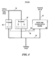
- FIG. 4 shows the structure of the PHD 52 of Figure 3.
- a set of receive queues or RX queues 64 is used for temporary buffering of packet headers and other messages bound for the FP 58.
- there are four RX queues 64 two queues for high-priority traffic and two queues for low-priority traffic.
- An example of high-priority traffic is traffic having a high Quality of Service (QOS) guarantee, such as a committed rate.
- QOS Quality of Service
- Low-priority traffic is traffic having a lower QOS or no QOS guarantee, such as best-efforts.
- QOS Quality of Service
- a set of transmit queues or TX queues 66 is used for temporary buffering of packet headers and other messages bound for the SARs 40, 42 from the FP 58.
- a route and classification engine 68 performs a route lookup and various packet filtering checks on behalf of the FP 58. The packet filtering operation is described below.
- the route and classification engine 68 receives status information from the queues 64, 66 via,signal lines 69, and makes this information available to the FP 58 in a manner described below.
- Packets are received by the inbound SAR 40 from the associated physical-layer circuitry 20 of Figure 2, and are stored in the packet memory 48.
- the inbound SAR 40 transfers the packet headers to an appropriate one of the RX queues 64 in the PHD 52.
- the FP 58 polls the PHD 52 to determine queue status, and retrieves the packet headers from the RX queues 64 as appropriate.
- the FP 58 sends certain information elements from each header to the route and classification engine 68 in a route and classification request.
- the route and classification engine 68 performs a route lookup and various packet filtering checks against the header elements in the request, and places the results of these checks into a result queue (described below).
- the FP 58 obtains the route lookup and classification results from the result queue, and uses these results to create a new header for the packet.
- the new header is transferred back to the PHD 52 via one of the TX queues 66, along with information identifying the internal circuit on which the packet should be forwarded after segmentation.
- the inbound SAR 40 retrieves the new header, places it in the packet memory 48 with the payload portion of the received packet, segments the new packet and transfers the resulting cells to the switch fabric 16 of Figure 1 on the internal circuit specified by the FP 58.
- the outbound SAR 42 receives packets from the switch fabric 16 of Figure 1, and reassembles these packets into the packet memory 50. Packet headers are sent to the PHD 52, and retrieved from the PHD 52 by the FP 58. For most packets, the route lookup and filtering checks will have already been performed during inbound processing, so these operations are not repeated. Some protocols, however, do require lookups and filtering for both inbound and outbound packets, and therefore these operations are optionally performed by the FP 58 in conjunction with the route and classification engine 68. If appropriate, the FP 58 formulates a new header for the packet, based in part on the identity of the internal circuit on which the segmented outbound packet is received.
- This new header is written to the PHD 52, along with transmit circuit information.
- the PHD 52 transfers the new header to the outbound SAR 42.
- the outbound SAR 42 places the new header in the packet memory 50 along with the packet payload, and transmits the packet to the associated physical layer interface 20 of Figure 2.
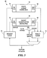
- FIG. 5 shows the structure of the route and classification engine 68.
- Requests from the FP 58 of Figure 3 are placed into a single request queue 70, and results are returned in a single result queue 72.
- Each queue 70 and 72 holds up to 16 request/result entries.
- a route lookup engine (RLE) 74 performs route lookups, typically based on a destination address (DA) included in the header.
- a packet classification engine (PCE) 76 performs packet filtering checks, based on specified information included in the packet header. The operation of the PCE 76 is described in more detail below.
- Input FIFO buffers 78 are placed between the request queue 70 and the RLE 74 and PCE 76, and output FIFO buffers 80 are placed between the RLE 74 and PCE 76 and the result queue 72.
- the FIFOs 78 and 80 provide a measure of decoupling between the processing performed by the RLE 74 and the processing performed by the PCE 76.
- a multiplexer 81 enables the FP 58 to read either the result queue 72, or status information including status from the request queue 70, the result queue 72, and the status appearing on the signal lines 69 of Figure 4. The structure of these entries is described below.
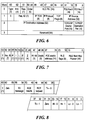
- Figure 6 shows the structure of the route and classification request that is passed to the PCE 76 and RLE 74 via the request queue 70 of Figure 5.
- the size of the request is four 64-hit words.
- IP TOS Type of Service
- TCP Flags The contents of the TCP Flags field of the received packet IP Source Address The IP Source Address of the received packet IP Dest. Addr.
- IP Destination Address of the received packet TCP/UDP Source Port The identifier of the TCP/UDP port on which the packet was received TCP/UDP Dest. Port The identifier of the TCP/UDP port for which the received packet is destined Reserved Unused reserved bits
- the appropriate fields of the request are provided to the respective input FIFOs 78 for the RLE 74 and PCE 76 of Figure 5.
- Some of the fields, such as the Req. ID and the IP Dest. Addr., are provided to both the RLE 74 and the PCE 76.
- Other fields are provided to only one or the other. The use of the fields routed to the PCE in particular is described below.
- Figure 7 and Figure 8 show the respective structures of the two different types of entries that are read from the route and classification engine 68 of Figure 4.
- Figure 7 shows a result entry, which is obtained from the result queue 72 of Figure 5 and conveys the result of a classification search.
- Figure 8 shows a status entry used to convey status information to the FP 58 of Figure 3.
- the fields of the status entry shown in Figure 8 are defined as follows: FIELD NAME DESCRIPTION Zero Unused, set to zero TX Message Remaining space in forwarding-processor-to-IOP message queue RCE Results Number of pending entries in result queue 72. Normally zero, because status inserted only when queue is empty. RCE Requests Number of empty entries in request queue 70 Tx-0 ⁇ Number of empty entries Tx-1 ⁇ in TX queues 66. Hi-0 ⁇ Hi-1
- the FP 58 of Figure 3 writes lookup and classification requests to the request queue 70.
- different information elements from the request are written simultaneously into the respective input FIFOs 78 for the RLE 74 and the PCE 76.
- the RLE 74 and PCE 76 operate on the separate pieces of each request independently, and in general finish their respective processing operations for a given request at different times.
- the results of these operations are written to the output FIFOs 80.
- both sets of results for a given packet have reached the front of the output FIFOs 80, a single combined result is written to the result queue 72.
- the combined results are read by the FP 58 and used to formulate new packet headers and circuit information for the SARs 40 and 42 of Figure 3, as discussed above.
- the FP 68 uses the route and classification engine 68 in a batch fashion. When there is sufficient room in the request queue 70, a burst of requests are written. Respective portions of each request are handled by the PCE 76 and RLE 74, as previously mentioned.
- the FP obtains results by issuing a read command to the RCE 68. For each read, a block of four 64-bit entries are returned to the FP 58 via the FP bus 56. Each block contains as many results from the result queue 72 as are available at the time of the read, and a number of status entries as padding. Thus, one of five different combinations of entries in a result block may be read:
- the FP 58 will generally issue read commands until the result queue 72 is empty, which is inferred whenever one or more status entries are included in the result block. The FP 58 then uses these results while the route and classification engine 68 processes the next batch of requests. The FP 58 uses the status information to manage the flow of requests, so that the RLE 74 and PCE 76 are kept busy and the queues 70 and 72 and FIFOs 78 and 80 are prevented from overflowing.
- One significant advantage of appending status information to results is improved efficiency in using the FP bus 56. Whenever the FP 58 issues a read for results, either useful results or useful status information is returned. Additionally, the result block is returned in burst fashion, so that overhead associated with reading is reduced. Also, the FP 58 obtains information about the queues around the RLE 74 and PCE 76, and about the RX queues 64 and TX queues 66, in a single read transaction.
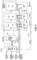
- Figure 9 shows the structure of the PCE 76 of Figure 5.
- Data representing filters and bindings are stored in a rule memory (RM) 82 and a criterion memory (CM) 84.
- the CM 84 includes three commonly addressed memories CMO 86, CM1 88 and CM2 90.
- Three comparison logic blocks 92, 94 and 96 are associated with respective ones of the criterion memories 86, 88 and 90.
- Addressing and control logic 98 decodes requests received from the request queue 70 of Figure 5, generates addresses for the RM 82 and the CM 84, sequences through multiple rules as required by each request, and generates results that are passed back to the result queue 72 of Figure 5.
- the addressing and control logic 98 also interfaces to the IOP 26 of Figure 2 to enable the reading and writing of the RM 82 and CM 84 by the IOP 26.
- Bus transceivers 100 provide the necessary data path between the IOP 26 and the RM 82 and CM 84.
- An AND gate 102 provides a single MATCH signal when corresponding MATCHn outputs from the comparison logic blocks 92, 94 and 96 are all true.
- Rule sets for packet filtering are typically originated by a Network Management Station (NMS), but can also be dynamically assigned by the FP 58 based on identified flows. Part or all of the following information is provided by the NMS or FP 58 for filters: IP Destination Address with mask; IP Source Address with mask; IP protocol identifier; TCP/UDP Source Port and Destination Port identifiers; IP Type of Service identifier and mask, and miscellaneous flags.
- the various information elements from a filter are compared with corresponding elements from each received packet in order to determine whether the packet matches the filter criteria. If so, some specific action for the filter is taken, such as intentionally discarding a packet. If not, some default action is typically taken, such as allowing the packet to proceed toward its destination.
- packet filters are represented as an ordered list of comparison sets that are searched linearly.
- the filter elements are divided into criteria (the comparison values) and rules (the list itself and the operators to be used for each comparison). This separation of rules and criteria is reflected in the use of separate rule memory (RM) 82 and criterion memory (CM) 84.
- the memories 82 and 84 are separately optimized for their respective functions, thus enhancing efficiency and performance.
- entries within the CM 84 can be referred to by multiple rules in the RM 82, further enhancing storage efficiency.
- the RM 82 contains an array of rule memory entries, each of which may be one of two types.
- a first type contains a set of operators and a pointer to a row of CM 84 that stores comparands for a corresponding filter.
- a second type contains a pointer to another rule memory entry. These entries are used to perform jumps between non-contiguous segments in a set of rules being searched sequentially.
- the RM 82 can contain up to 16K entries.
- the CM 84 is segmented into three separate memories CMO 86, CM1 88 and CM2 90, each of which can contain up to 4K entries in the illustrated embodiment.
- the organization of the CM 84 exploits a hierarchy that is inherent in IP packet classification. Because filtering on certain fields is usually accompanied by filtering based on other fields as well, it is reasonable to restrict which fields are stored in the separate memories CMO, CM1, and CM2. These restrictions further enhance storage efficiency.
- the most commonly filtered fields, Source Address and Destination Address are supported in all three memories CMO 86, CM1 88 and CM2 90. As described below, other fields are supported only in CM1 88 and/or CM2 90. This architecture maximizes the flexibility with which space in the CM 84 can be allocated, while at the same time enabling powerful parallel searches.
- the structure and use of CM 84 are described in more detail below.
- PCE packet classification engine
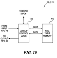
- Figure 10 shows the structure of the route lookup engine (RLE) 74 of Figure 5.
- a memory 110 is used to store forwarding tables provided by the IOP 26 of Figure 2.
- Lookup control logic 112 controls the operation of the memory 110, and contains interfaces to the IOP 26, the RLE input FIFO 78 of Figure 5, and the RLE output FIFO 80 of Figure 5.
- the RLE 74 is a hardware search engine used to determine a next-hop index for the forwarding processor 58 of Figure 3.
- the RLE performs both unicast and multicast IP address lookups on IP networks, for example Virtual private Networks (VPNs) and the public Internet.
- IP networks for example Virtual private Networks (VPNs) and the public Internet.
- VPNs Virtual private Networks
- Each IP network is assigned a root of a forwarding table in the memory 110 that is specific to that network.
- Searching is performed first on the IP destination address (DA), and subsequently on the IP source address (SA) if the packet is multicast. This operation takes place automatically, and normally terminates when a next hop index is found, or the end of the search key (DA or SA) is reached without an index having been found.
- Various lookup algorithms may be used, including so-called Patricia tree algorithms.
- a successful search returns a next hop pointer found in the forwarding table at a location corresponding to the search key (either DA or SA).
- the next hop pointer is a pointer into a pre-defined table of network addresses available to the forwarding processor 58 for creating forwarding envelopes for messages.
Landscapes
- Engineering & Computer Science (AREA)
- Computer Networks & Wireless Communication (AREA)
- Signal Processing (AREA)
- Data Exchanges In Wide-Area Networks (AREA)
- Information Retrieval, Db Structures And Fs Structures Therefor (AREA)
- Small-Scale Networks (AREA)
Abstract
Description
- The present invention is related to the field of data communication networks.
- In data communication networks, network devices such as switches are used to route packets through the network. Each switch typically has a number of line interfaces, each connected to a different network segment. When a packet is received at a given line interface, forwarding logic determines which line interface the packet should be transmitted from, and the packet is transferred to the appropriate outgoing line interface to be sent toward its destination in the network.
- It is known to employ specialized forwarding logic in conjunction with a microprocessor on the line interface. The microprocessor is responsible for overall packet processing and forwarding. The forwarding logic stores one or more forwarding tables in high-speed memory. The forwarding tables contain information indicating how packets should be forwarded, typically based on a destination address contained within the packet. The forwarding tables are maintained by a background process executing in the switch. When a packet is received at a line interface, the microprocessor generates a lookup request containing selected information from the packet, and issues the lookup request to the forwarding logic. The forwarding logic carries out a specialized search of one or more forwarding tables, and returns a lookup result to the microprocessor. The lookup result contains an indication of whether forwarding information has been found, and if so then it contains the forwarding information itself. The microprocessor uses the forwarding information to forward the packet. This architecture is used to achieve packet forwarding rates greater than what is achievable using a microprocessor alone.
- It is also known to perform packet filtering in network devices such as switches. Packet filtering can be used to achieve various network management goals, such as traffic monitoring and security goals. Filtering criteria are established by network administrators, and provided to the switches or other devices that carry out the filtering operation. Packets received by the switches are examined to determine whether their characteristics match the criteria for any of the established filters. For packets that satisfy the criteria for one or more filters, predetermined actions associated with those filters are carried out. For example, under certain circumstances it may be desirable that packets originating from a given network node be discarded rather than being forwarded in the network. A filter can be defined in which the criterion is that a packet source address exactly match a specific value, which is the address of the node whose packets are to be discarded. The action associated with the filter is the discarding of the packet. When a packet is received whose source address satisfies this criterion, it is discarded rather than being forwarded in the normal fashion.
- There are a number of different kinds of criteria that may be used to filter packets. These criteria include exact matches as well as range checking, i.e., checking whether a value in a packet falls in some range of values. Numerous packet parameters can be used as criteria, such as source address, destination address, port identifiers, type of service, and others. To be useful, packet filtering processes must allow filters to be flexibly defined using different combinations of these and other criteria.
- Because of this complexity inherent in packet filtering, it has traditionally been performed largely or exclusively in software within switches or other network devices supporting packet filtering. Software-based filtering, however, presents a bottleneck when high packet forwarding performance is required. Network administrators have had to make undesirable tradeoffs between network responsiveness and network security, for example, because previous systems have not been capable of robust packet filtering at line rates.
- In accordance with the present invention, packet processing logic in a network device is disclosed that provides high-speed forwarding searching along with packet classification for packet filtering purposes. A novel request and response architecture is used between a packet-processing microprocessor and dedicated searching and classification logic to avoid communications bottlenecks that might otherwise reduce forwarding performance.
- The packet processing logic includes a request queue for receiving lookup requests from a packet processor, where each request includes various information elements from a received packet, and each request indicates that both a route lookup and a packet classification are to be performed based on the information elements contained in the request. A route lookup engine (RLE) has an input coupled to the request queue for receiving selected information elements from the requests. Similarly, a packet classification engine (PCE) has an input coupled to the request queue. Based on the information elements in each request, the RLE searches for forwarding information indicating how the packet corresponding to the request should be forwarded, and the PCE performs a classification process and generates classification information about the packet corresponding to the request. For each request, the forwarding information from the RLE and the classification information from the PCE are combined into a single result stored in a result queue. Each result is provided to the packet processor in a single communication transaction therewith.
- This shared request and result architecture enhances the efficiency and speed of communication between the packet processor and the PCE and RLE, allowing for high-speed packet forwarding and classification.
- Other aspects, features, and advantages of the present invention are disclosed in the detailed description that follows.
-
- Figure 1 is a block diagram of a network switch incorporating a packet classification engine in accordance with the present invention;
- Figure 2 is a block diagram of a line interface in the network s witch of Figure 1;
- Figure 3 is a block diagram of a packet forwarding engine on t he line interface of Figure 2;
- Figure 4 is a block diagram of a packet header distributor application-specific integrated circuit (ASIC) in the forwarding engine of Figure 3;
- Figure 5 is a block diagram of a route and classification engine in the packet header distributor ASIC of Figure 4;
- Figure 6 is a diagram of the structure of a route and classification request passed to the route and classification engine of Figure 5;
- Figure 7 is a diagram of the structure of a route and classification result provided by the route and classification engine of Figure 5;
- Figure 8 is a diagram of the structure of a status indication pro vided by the route and classification engine of Figure 5;
- Figure 9 is a block diagram of a packet classification engine (P CE) in the route and classification engine of Figure 5; and
- Figure 10 is a block diagram of a route lookup engine (RLE) in the route and classification engine of Figure 5.
-
- In Figure 1, a
network switch 10 is shown as including a number ofline interfaces 12 connected torespective network segments 14. Theline interfaces 12 are connected to aswitch fabric 16 used to provide connections among theline interfaces 12 for packet forwarding. The overall operation of theswitch 10, including the dynamic configuration of theswitch fabric 16, is controlled by aswitch control 18. In general, thevarious network segments 14 may be of different types. For example, certain of thenetwork segments 14 may be optical links operating at any of a variety of standard signalling rates, such as OC-3/STM-1 and OC-12/STM-4. Others of thenetwork segments 14 may be non-optical links employing coaxial cable, for example, and carrying signals of different formats. - Each
line interface 12 is of course designed for operation with the specific type ofnetwork segment 14 to which it connects. The primary tasks of eachline interface 12 are to transfer packets or frames received from an attachednetwork segment 14 to anotherline interface 12 via theswitch fabric 16 for forwarding on anetwork segment 14 attached to theother line interface 12, and to receive packets from theother line interfaces 12 via theswitch fabric 16 for forwarding on the attachednetwork segment 14. - Figure 2 shows the structure of one type of
line interface 12. This interface contains four separate optical interface ports, each including physical input/output andframing circuitry 20 and a forwarding engine 22. The forwarding engines 22 are all connected to switchfabric interface logic 24, which interfaces with theswitch fabric 16 of Figure 1. The forwarding engines also interface with a line interface I/O processor (IOP) 26. Timingcontrol logic 28 andDC power circuitry 30 are also included. - Each forwarding engine 22 provides a bidirectional data path between a connected physical I/
O block 20 and theswitch fabric interface 24. Received packets are segmented into multiple fixed-size ATM-like cells for transfer through theswitch fabric 16 of Figure 1 to anotherline interface 12. Cells received from theswitch fabric 16 via theswitch fabric interface 24 are reassembled into packets for outgoing transfer to the connected physical I/O block 20. - The
IOP 26 is a general-purpose processor that performs background functions, i.e. functions that support the forwarding of packets that are not carried out on a per-packet basis. One function performed by theIOP 26 is receiving packet forwarding information and packet filtering information from theswitch control 18 of Figure 1, and distributing the information to the forwarding engines 22. This process is described below. - Figure 3 shows a block diagram of a forwarding engine 22. An inbound segmentation-and-reassembly (SAR)
logic block 40 provides a data path from a physical I/O block 20 to theswitch fabric 16 of Figure 2, and an outboundSAR logic block 42 provides a data path from theswitch fabric 16 to the respective physical I/O block 20. EachSAR respective control memory packet memory - The
SAR devices bit PCI bus 54. As described in more detail below, thePHD ASIC 52 provides FIFO queue interfaces between thePCI bus 54 and a separate 64-bit bus 56. Thebus 56 connects thePHD ASIC 52 with a forwarding processor (FP) 58 and forwardingprocessor memory 60. ThePHD ASIC 52 is also connected to theIOP 26 of Figure 2 by aseparate bus 62. - Figure 4 shows the structure of the
PHD 52 of Figure 3. A set of receive queues orRX queues 64 is used for temporary buffering of packet headers and other messages bound for theFP 58. As shown, there are fourRX queues 64, two queues for high-priority traffic and two queues for low-priority traffic. An example of high-priority traffic is traffic having a high Quality of Service (QOS) guarantee, such as a committed rate. Low-priority traffic is traffic having a lower QOS or no QOS guarantee, such as best-efforts. For each priority level, there is one queue (labeled "0") for traffic originating from theinbound SAR 40, and another queue (labeled "1") for traffic originating from theoutbound SAR 42. A set of transmit queues orTX queues 66 is used for temporary buffering of packet headers and other messages bound for theSARs FP 58. A route andclassification engine 68 performs a route lookup and various packet filtering checks on behalf of theFP 58. The packet filtering operation is described below. The route andclassification engine 68 receives status information from thequeues signal lines 69, and makes this information available to theFP 58 in a manner described below. - The overall operation of a forwarding engine 22 will be described with reference to Figure 3 and Figure 4. Packets are received by the
inbound SAR 40 from the associated physical-layer circuitry 20 of Figure 2, and are stored in thepacket memory 48. Theinbound SAR 40 transfers the packet headers to an appropriate one of theRX queues 64 in thePHD 52. TheFP 58 polls thePHD 52 to determine queue status, and retrieves the packet headers from theRX queues 64 as appropriate. As part of the header processing, theFP 58 sends certain information elements from each header to the route andclassification engine 68 in a route and classification request. The route andclassification engine 68 performs a route lookup and various packet filtering checks against the header elements in the request, and places the results of these checks into a result queue (described below). TheFP 58 obtains the route lookup and classification results from the result queue, and uses these results to create a new header for the packet. The new header is transferred back to thePHD 52 via one of theTX queues 66, along with information identifying the internal circuit on which the packet should be forwarded after segmentation. Theinbound SAR 40 retrieves the new header, places it in thepacket memory 48 with the payload portion of the received packet, segments the new packet and transfers the resulting cells to theswitch fabric 16 of Figure 1 on the internal circuit specified by theFP 58. - In the outbound direction, the
outbound SAR 42 receives packets from theswitch fabric 16 of Figure 1, and reassembles these packets into thepacket memory 50. Packet headers are sent to thePHD 52, and retrieved from thePHD 52 by theFP 58. For most packets, the route lookup and filtering checks will have already been performed during inbound processing, so these operations are not repeated. Some protocols, however, do require lookups and filtering for both inbound and outbound packets, and therefore these operations are optionally performed by theFP 58 in conjunction with the route andclassification engine 68. If appropriate, theFP 58 formulates a new header for the packet, based in part on the identity of the internal circuit on which the segmented outbound packet is received. This new header is written to thePHD 52, along with transmit circuit information. ThePHD 52 transfers the new header to theoutbound SAR 42. Theoutbound SAR 42 places the new header in thepacket memory 50 along with the packet payload, and transmits the packet to the associatedphysical layer interface 20 of Figure 2. - Figure 5 shows the structure of the route and
classification engine 68. Requests from theFP 58 of Figure 3 are placed into asingle request queue 70, and results are returned in asingle result queue 72. Eachqueue PCE 76 is described in more detail below. Input FIFO buffers 78 are placed between therequest queue 70 and theRLE 74 andPCE 76, and output FIFO buffers 80 are placed between theRLE 74 andPCE 76 and theresult queue 72. The FIFOs 78 and 80 provide a measure of decoupling between the processing performed by theRLE 74 and the processing performed by thePCE 76. A multiplexer 81 enables theFP 58 to read either theresult queue 72, or status information including status from therequest queue 70, theresult queue 72, and the status appearing on thesignal lines 69 of Figure 4. The structure of these entries is described below. - Figure 6 shows the structure of the route and classification request that is passed to the
PCE 76 andRLE 74 via therequest queue 70 of Figure 5. The size of the request is four 64-hit words. The various fields are defined as follows:FIELD NAME DESCRIPTION Type RLE Entry type: 0=Node, 1=Leaf Ind. RLE Indirect route: 1=Indirect, 0=Direct Res. Unused reserved bit Order No. of DA bits to add to RLE pointer RLE Ptr. Base address of RLE entry to which DA is added (based on Order) PCE Root 0Starting address for PCE rule 0PCE Root 1Starting address for PCE rule 10 Set to zero, used for alignment checking Req. ID Request identifier, copied to result to enable matching with request IP TOS The contents of the Type of Service (TOS) field of the received packet IP Protocol The contents of the Protocol field of the received packet TCP Flags The contents of the TCP Flags field of the received packet IP Source Address The IP Source Address of the received packet IP Dest. Addr. The IP Destination Address of the received packet TCP/UDP Source Port The identifier of the TCP/UDP port on which the packet was received TCP/UDP Dest. Port The identifier of the TCP/UDP port for which the received packet is destined Reserved Unused reserved bits - As shown in the above table, there is a provision for two separate sets of classification checks, one beginning at an address labeled "
PCE Root 0" and the other as "PCE Root 1". The significance of these separate starting addresses is described below. - As previously noted, the appropriate fields of the request are provided to the
respective input FIFOs 78 for theRLE 74 andPCE 76 of Figure 5. Some of the fields, such as the Req. ID and the IP Dest. Addr., are provided to both theRLE 74 and thePCE 76. Other fields are provided to only one or the other. The use of the fields routed to the PCE in particular is described below. - Figure 7 and Figure 8 show the respective structures of the two different types of entries that are read from the route and
classification engine 68 of Figure 4. Figure 7 shows a result entry, which is obtained from theresult queue 72 of Figure 5 and conveys the result of a classification search. Figure 8 shows a status entry used to convey status information to theFP 58 of Figure 3. - The fields of the result entry shown in Figure 7 are defined as follows:
FIELD NAME DESCRIPTION T Type: 0 = PCE Result, 1 = PCE Status Req. ID Request Identifier (from the request) P PCE Match NOT Found: 0 = Match Found, 1 = Match NOT Found I RLE Indirect Route: 0 = Normal, 1 = Indirect L RLE Long Search: 0 = Short, 1 = Long E Error indicator: 0 = Normal, 1 = Error Z Zero padding R1-M Match in PCE Root 1 (valid only if P = 0): 0 = Match in root root 1Depth Depth of route lookup search PCE Match Addr. Address of last rule checked in PCE RLE Flags Flags from RLE table entry RLE Next Hop Ptr. Pointer from RLE table entry - The fields of the status entry shown in Figure 8 are defined as follows:
FIELD NAME DESCRIPTION Zero Unused, set to zero TX Message Remaining space in forwarding-processor-to-IOP message queue RCE Results Number of pending entries in result queue 72. Normally zero, because status inserted only when queue is empty.RCE Requests Number of empty entries in request queue 70Tx-0 ┐ Number of empty entries Tx-1 ┘ in TX queues 66.Hi-0 ┐ Hi-1 | Number of empty entries in Lo-0 | RX queues 64.Lo- 1 ┘ - The general operation of the route and
classification engine 68 will be described with reference to Figure 5 through Figure 8. TheFP 58 of Figure 3 writes lookup and classification requests to therequest queue 70. When a request reaches the front of therequest queue 70, different information elements from the request are written simultaneously into therespective input FIFOs 78 for theRLE 74 and thePCE 76. TheRLE 74 andPCE 76 operate on the separate pieces of each request independently, and in general finish their respective processing operations for a given request at different times. The results of these operations are written to theoutput FIFOs 80. When both sets of results for a given packet have reached the front of theoutput FIFOs 80, a single combined result is written to theresult queue 72. The combined results are read by theFP 58 and used to formulate new packet headers and circuit information for theSARs - More particularly, the
FP 68 uses the route andclassification engine 68 in a batch fashion. When there is sufficient room in therequest queue 70, a burst of requests are written. Respective portions of each request are handled by thePCE 76 andRLE 74, as previously mentioned. The FP obtains results by issuing a read command to theRCE 68. For each read, a block of four 64-bit entries are returned to theFP 58 via theFP bus 56. Each block contains as many results from theresult queue 72 as are available at the time of the read, and a number of status entries as padding. Thus, one of five different combinations of entries in a result block may be read: - 1. 4 result entries
- 2. 3 result entries followed by 1 status entry
- 3. 2 result entries followed by 2 status entries
- 4. 1 result entry followed by 3 status entries
- 5. 4 status entries
- The
FP 58 will generally issue read commands until theresult queue 72 is empty, which is inferred whenever one or more status entries are included in the result block. TheFP 58 then uses these results while the route andclassification engine 68 processes the next batch of requests. TheFP 58 uses the status information to manage the flow of requests, so that theRLE 74 andPCE 76 are kept busy and thequeues FIFOs - It will be noted that in the illustrated embodiment, there is only one status entry that can be read, and the multiple status entries in a result block represent multiple reads of this single entry. In alternative embodiments it may be useful to provide additional, lower-priority information in the second through fourth status entries, for example for statistics gathering purposes or other background processing.
- One significant advantage of appending status information to results is improved efficiency in using the
FP bus 56. Whenever theFP 58 issues a read for results, either useful results or useful status information is returned. Additionally, the result block is returned in burst fashion, so that overhead associated with reading is reduced. Also, theFP 58 obtains information about the queues around theRLE 74 andPCE 76, and about theRX queues 64 andTX queues 66, in a single read transaction. - Figure 9 shows the structure of the
PCE 76 of Figure 5. Data representing filters and bindings (discussed below) are stored in a rule memory (RM) 82 and a criterion memory (CM) 84. TheCM 84 includes three commonly addressedmemories CMO 86,CM1 88 andCM2 90. Three comparison logic blocks 92, 94 and 96 are associated with respective ones of thecriterion memories logic 98 decodes requests received from therequest queue 70 of Figure 5, generates addresses for theRM 82 and theCM 84, sequences through multiple rules as required by each request, and generates results that are passed back to theresult queue 72 of Figure 5. The addressing and controllogic 98 also interfaces to theIOP 26 of Figure 2 to enable the reading and writing of theRM 82 andCM 84 by theIOP 26.Bus transceivers 100 provide the necessary data path between theIOP 26 and theRM 82 andCM 84. An ANDgate 102 provides a single MATCH signal when corresponding MATCHn outputs from the comparison logic blocks 92, 94 and 96 are all true. - Rule sets for packet filtering are typically originated by a Network Management Station (NMS), but can also be dynamically assigned by the
FP 58 based on identified flows. Part or all of the following information is provided by the NMS orFP 58 for filters: IP Destination Address with mask; IP Source Address with mask; IP protocol identifier; TCP/UDP Source Port and Destination Port identifiers; IP Type of Service identifier and mask, and miscellaneous flags. The various information elements from a filter are compared with corresponding elements from each received packet in order to determine whether the packet matches the filter criteria. If so, some specific action for the filter is taken, such as intentionally discarding a packet. If not, some default action is typically taken, such as allowing the packet to proceed toward its destination. - Traditionally, packet filters are represented as an ordered list of comparison sets that are searched linearly. In the
PCE 76, the filter elements are divided into criteria (the comparison values) and rules (the list itself and the operators to be used for each comparison). This separation of rules and criteria is reflected in the use of separate rule memory (RM) 82 and criterion memory (CM) 84. Thememories CM 84 can be referred to by multiple rules in theRM 82, further enhancing storage efficiency. - The
RM 82 contains an array of rule memory entries, each of which may be one of two types. A first type contains a set of operators and a pointer to a row ofCM 84 that stores comparands for a corresponding filter. A second type contains a pointer to another rule memory entry. These entries are used to perform jumps between non-contiguous segments in a set of rules being searched sequentially. In the illustrated embodiment, theRM 82 can contain up to 16K entries. - The
CM 84 is segmented into threeseparate memories CMO 86,CM1 88 andCM2 90, each of which can contain up to 4K entries in the illustrated embodiment. The organization of theCM 84 exploits a hierarchy that is inherent in IP packet classification. Because filtering on certain fields is usually accompanied by filtering based on other fields as well, it is reasonable to restrict which fields are stored in the separate memories CMO, CM1, and CM2. These restrictions further enhance storage efficiency. The most commonly filtered fields, Source Address and Destination Address, are supported in all threememories CMO 86,CM1 88 andCM2 90. As described below, other fields are supported only inCM1 88 and/orCM2 90. This architecture maximizes the flexibility with which space in theCM 84 can be allocated, while at the same time enabling powerful parallel searches. The structure and use ofCM 84 are described in more detail below. - The operation of the packet classification engine (PCE) 76 proceeds generally as follows:
- 1. The
RM 82 and theCM 84 are initialized by theIOP 26 of Figure 2. This happens at power-up, and during operation either by dynamic assignment or by a Network Management Station (NMS) (discussed below). - 2. A packet classification request submitted by the
FP 58 is retrieved from therequest queue 70 of Figure 5. - 3. The
RM 82 is indexed by the contents of theroot 0 address of the request to retrieve the first rule memory entry of the search. If the entry is a pointer type, then this step is repeated for the rule memory address in the retrieved entry. It is possible for this step to repeat multiple times. - 4. If the retrieved rule memory entry is an operator type, then a criterion memory
entry is retrieved at the location specified by the CM address in the rule memory entry.
Selected comparands from the
CM 84 are compared with corresponding fields of the request, according to the operator in the rule memory entry. Various fields may be masked as described above. - 5. The rule memory address increments by one until either an entry having a DONE bit set to one is reached, or a match condition is found (i.e. the result of the comparison operation is TRUE). A rule may have its CARRY bit set, which requires that the next rule also evaluate as TRUE before a match is declared.
- 6. If any rule memory entry encountered in the search is a pointer type of entry, it points to another rule memory entry rather than to a criterion memory entry. In this case, sequential rule evaluation continues beginning at the pointed-to rule memory entry.
- 7. The above process is performed once beginning at the
root 0 address in the request. If DONE is reached for the filters associated withroot 0, then the process is repeated beginning at theroot 1 address. When a match is found, the result indicates whether it has been found usingroot 0 orroot 1 rules. - 8. When the search terminates, either by encountering a match or by encountering
DONE in the
root 1 search, a result is written back to theresult queue 72 indicating the results of the filtering check. The result contains the address of the last rule checked, and whether or not a match has been found. If a match has been found, the address is used by theFP 58 to index into an action table, which initiates an action appropriate to the result. For example, if the match is for a rule indicating that all packets having a DA of less than a certain value should be dropped, then the action table points to a routine that causes the packet to be intentionally discarded. -
- Figure 10 shows the structure of the route lookup engine (RLE) 74 of Figure 5. A
memory 110 is used to store forwarding tables provided by theIOP 26 of Figure 2.Lookup control logic 112 controls the operation of thememory 110, and contains interfaces to theIOP 26, theRLE input FIFO 78 of Figure 5, and theRLE output FIFO 80 of Figure 5. - The
RLE 74 is a hardware search engine used to determine a next-hop index for the forwardingprocessor 58 of Figure 3. The RLE performs both unicast and multicast IP address lookups on IP networks, for example Virtual private Networks (VPNs) and the public Internet. Each IP network is assigned a root of a forwarding table in thememory 110 that is specific to that network. - Searching is performed first on the IP destination address (DA), and subsequently on the IP source address (SA) if the packet is multicast. This operation takes place automatically, and normally terminates when a next hop index is found, or the end of the search key (DA or SA) is reached without an index having been found. Various lookup algorithms may be used, including so-called Patricia tree algorithms. As shown in the description of the result above, a successful search returns a next hop pointer found in the forwarding table at a location corresponding to the search key (either DA or SA). The next hop pointer is a pointer into a pre-defined table of network addresses available to the forwarding
processor 58 for creating forwarding envelopes for messages. - A submission and response architecture for packet route lookup and classification requests has been described. It will be apparent to those skilled in the art that other modifications to and variations of the above-described technique are possible without departing from the inventive concepts disclosed herein. Accordingly, the invention should be viewed as limited solely by the scope of the appended claims.
Claims (8)
- Packet processing apparatus, comprising:a request queue operative to receive lookup requests from a packet processor, each request including various information elements from a corresponding received packet and indicating that both a route lookup and a packet classification are to be performed based on the information elements contained in the request;a route lookup engine (RLE) having an RLE input queue and an RLE output queue, the RLE input queue being coupled to the request queue and being operative to receive selected information elements of requests from the request queue, the RLE being operative based on the selected information elements of each request to search for forwarding information indicating how the packet corresponding to the request should be forwarded, the RLE being operative to place the forwarding information into the RLE output queue upon completion of the search;a packet classification engine (PCE) having a PCE input queue and a PCE output queue, the PCE input queue being coupled to the request queue and being operative to receive selected information elements of requests from the request queue, the PCE being operative based on the selected information elements of each request to perform a classification process and to generate classification information about the packet corresponding to the request, the PCE being operative to place the classification information into the PCE output queue upon completion of the classification process; anda result queue coupled to the RLE output queue and the PCE output queue, the result queue being operative to (i) receive the forwarding information and the classification information resulting from each request, (i) include the received forwarding information and classification information in a single result for each request, and (iii) provide each result to the packet processor in a corresponding communication transaction therewith.
- Packet processing apparatus according to claim 1, wherein the PCE contains a rule memory including rule memory entries, each rule memory entry representing corresponding classification criteria applied in the classification process, and wherein the classification information included in each result includes an address of a rule memory entry whose corresponding classification criteria are satisfied by the request for which the result has been created.
- Packet processing apparatus according to claim 1, wherein the set of information elements used by the PCE and the set of information elements used by the RLE overlap but are not identical.
- Packet processing apparatus according to claim 3, wherein the overlapping information elements include a destination address from received packets.
- Packet processing apparatus according to claim 1, wherein the request queue and the result queue each have associated status information indicating the number of empty entries therein, and further comprising read logic operative to combine the status information with a result from the result queue and to provide the combined result to the packet processor as part of a single corresponding communication transaction therewith.
- Packet processing apparatus according to claim 5, wherein the read logic is coupled to the packet processor via a bus, and wherein the combined result is provided to the packet processor as a multi-word block over multiple successive bus cycles.
- Packet processing apparatus according to claim 6, wherein the combined result block is a fixed size block including as many result entries as are available in the result queue at the time the result block is provided to the packet processor, and as many status entries as are necessary to pad the result block to its fixed size.
- Packet processing apparatus according to claim 5, wherein the read logic is coupled to the packet processor via a bus, and further comprising additional queues also coupled to the packet processor via the bus, each additional queue having associated status information indicating the number of empty entries therein, and wherein the status information of the additional queues is also included in the combined result.
Applications Claiming Priority (2)
| Application Number | Priority Date | Filing Date | Title |
|---|---|---|---|
| US460299 | 1999-12-13 | ||
| US09/460,299 US6463067B1 (en) | 1999-12-13 | 1999-12-13 | Submission and response architecture for route lookup and packet classification requests |
Publications (3)
| Publication Number | Publication Date |
|---|---|
| EP1109363A2 true EP1109363A2 (en) | 2001-06-20 |
| EP1109363A3 EP1109363A3 (en) | 2003-11-26 |
| EP1109363B1 EP1109363B1 (en) | 2005-08-10 |
Family
ID=23828141
Family Applications (1)
| Application Number | Title | Priority Date | Filing Date |
|---|---|---|---|
| EP00310913A Expired - Lifetime EP1109363B1 (en) | 1999-12-13 | 2000-12-08 | Routing engine |
Country Status (5)
| Country | Link |
|---|---|
| US (1) | US6463067B1 (en) |
| EP (1) | EP1109363B1 (en) |
| JP (1) | JP3640299B2 (en) |
| CA (1) | CA2327564C (en) |
| DE (1) | DE60021846T2 (en) |
Cited By (2)
| Publication number | Priority date | Publication date | Assignee | Title |
|---|---|---|---|---|
| EP1330079A1 (en) * | 2002-01-21 | 2003-07-23 | Samsung Electronics Co., Ltd. | Router system and method of duplicating one forwarding engine |
| EP1718008A3 (en) * | 2005-04-28 | 2006-12-20 | Fujitsu Ten Limited | Gateway apparatus and routing method |
Families Citing this family (34)
| Publication number | Priority date | Publication date | Assignee | Title |
|---|---|---|---|---|
| US6990103B1 (en) | 1999-07-13 | 2006-01-24 | Alcatel Canada Inc. | Method and apparatus for providing distributed communication routing |
| US7068661B1 (en) | 1999-07-13 | 2006-06-27 | Alcatel Canada Inc. | Method and apparatus for providing control information in a system using distributed communication routing |
| US6963572B1 (en) * | 1999-10-22 | 2005-11-08 | Alcatel Canada Inc. | Method and apparatus for segmentation and reassembly of data packets in a communication switch |
| US6687247B1 (en) * | 1999-10-27 | 2004-02-03 | Cisco Technology, Inc. | Architecture for high speed class of service enabled linecard |
| US6711153B1 (en) * | 1999-12-13 | 2004-03-23 | Ascend Communications, Inc. | Route lookup engine |
| US6848029B2 (en) * | 2000-01-03 | 2005-01-25 | Dirk Coldewey | Method and apparatus for prefetching recursive data structures |
| US6697334B1 (en) | 2000-01-18 | 2004-02-24 | At&T Corp. | Method for designing a network |
| TW498650B (en) * | 2000-03-22 | 2002-08-11 | Ind Tech Res Inst | Flexible and highly efficient packet classification method |
| US6957272B2 (en) * | 2000-05-24 | 2005-10-18 | Alcatel Internetworking (Pe), Inc. | Stackable lookup engines |
| US7286565B1 (en) * | 2000-06-28 | 2007-10-23 | Alcatel-Lucent Canada Inc. | Method and apparatus for packet reassembly in a communication switch |
| US8619793B2 (en) * | 2000-08-21 | 2013-12-31 | Rockstar Consortium Us Lp | Dynamic assignment of traffic classes to a priority queue in a packet forwarding device |
| JP3646638B2 (en) * | 2000-09-06 | 2005-05-11 | 日本電気株式会社 | Packet switching apparatus and switch control method used therefor |
| US7061907B1 (en) * | 2000-09-26 | 2006-06-13 | Dell Products L.P. | System and method for field upgradeable switches built from routing components |
| US7193968B1 (en) * | 2001-02-08 | 2007-03-20 | Cisco Technology, Inc. | Sample netflow for network traffic data collection |
| US6940854B1 (en) * | 2001-03-23 | 2005-09-06 | Advanced Micro Devices, Inc. | Systems and methods for determining priority based on previous priority determinations |
| US7142509B1 (en) * | 2001-09-12 | 2006-11-28 | Extreme Networks | Method and apparatus providing for delivery of streaming media |
| US7464180B1 (en) * | 2001-10-16 | 2008-12-09 | Cisco Technology, Inc. | Prioritization and preemption of data frames over a switching fabric |
| US7389360B1 (en) * | 2001-11-05 | 2008-06-17 | Juniper Networks, Inc. | Context switched route lookup key engine |
| US7813346B1 (en) * | 2001-11-21 | 2010-10-12 | Juniper Networks, Inc. | Filter-based forwarding in a network |
| US7239639B2 (en) * | 2001-12-27 | 2007-07-03 | 3Com Corporation | System and method for dynamically constructing packet classification rules |
| US7106740B1 (en) * | 2002-01-02 | 2006-09-12 | Juniper Networks, Inc. | Nexthop to a forwarding table |
| JP2003324464A (en) * | 2002-04-30 | 2003-11-14 | Fujitsu Ltd | Data search apparatus and data search method |
| US7280527B2 (en) * | 2002-05-13 | 2007-10-09 | International Business Machines Corporation | Logically grouping physical ports into logical interfaces to expand bandwidth |
| US7372864B1 (en) | 2002-08-01 | 2008-05-13 | Applied Micro Circuits Corporation | Reassembly of data fragments in fixed size buffers |
| US7701949B1 (en) * | 2003-06-24 | 2010-04-20 | Cisco Technology, Inc. | System and method for switching high priority traffic with low latency |
| US7903555B2 (en) * | 2003-12-17 | 2011-03-08 | Intel Corporation | Packet tracing |
| US7558890B1 (en) * | 2003-12-19 | 2009-07-07 | Applied Micro Circuits Corporation | Instruction set for programmable queuing |
| US20050198362A1 (en) * | 2003-12-31 | 2005-09-08 | Navada Muraleedhara H. | Exception packet forwarding |
| US7649879B2 (en) * | 2004-03-30 | 2010-01-19 | Extreme Networks, Inc. | Pipelined packet processor |
| US7889750B1 (en) * | 2004-04-28 | 2011-02-15 | Extreme Networks, Inc. | Method of extending default fixed number of processing cycles in pipelined packet processor architecture |
| US7817633B1 (en) | 2005-12-30 | 2010-10-19 | Extreme Networks, Inc. | Method of providing virtual router functionality through abstracted virtual identifiers |
| US7894451B2 (en) * | 2005-12-30 | 2011-02-22 | Extreme Networks, Inc. | Method of providing virtual router functionality |
| US7822033B1 (en) | 2005-12-30 | 2010-10-26 | Extreme Networks, Inc. | MAC address detection device for virtual routers |
| US8605732B2 (en) | 2011-02-15 | 2013-12-10 | Extreme Networks, Inc. | Method of providing virtual router functionality |
Citations (1)
| Publication number | Priority date | Publication date | Assignee | Title |
|---|---|---|---|---|
| WO1999000935A1 (en) * | 1997-06-30 | 1999-01-07 | Sun Microsystems, Inc. | A system and method for a multi-layer network element |
Family Cites Families (8)
| Publication number | Priority date | Publication date | Assignee | Title |
|---|---|---|---|---|
| US5905723A (en) * | 1993-06-23 | 1999-05-18 | Cabletron Systems, Inc. | System for achieving scalable router performance |
| US5918074A (en) * | 1997-07-25 | 1999-06-29 | Neonet Llc | System architecture for and method of dual path data processing and management of packets and/or cells and the like |
| US6285679B1 (en) * | 1997-08-22 | 2001-09-04 | Avici Systems, Inc. | Methods and apparatus for event-driven routing |
| US6069895A (en) * | 1997-08-29 | 2000-05-30 | Nortel Networks Corporation | Distributed route server |
| US6160811A (en) * | 1997-09-12 | 2000-12-12 | Gte Internetworking Incorporated | Data packet router |
| US6266706B1 (en) * | 1997-09-15 | 2001-07-24 | Effnet Group Ab | Fast routing lookup system using complete prefix tree, bit vector, and pointers in a routing table for determining where to route IP datagrams |
| US6259699B1 (en) * | 1997-12-30 | 2001-07-10 | Nexabit Networks, Llc | System architecture for and method of processing packets and/or cells in a common switch |
| US6192051B1 (en) * | 1999-02-26 | 2001-02-20 | Redstone Communications, Inc. | Network router search engine using compressed tree forwarding table |
-
1999
- 1999-12-13 US US09/460,299 patent/US6463067B1/en not_active Expired - Fee Related
-
2000
- 2000-12-04 CA CA002327564A patent/CA2327564C/en not_active Expired - Fee Related
- 2000-12-08 DE DE60021846T patent/DE60021846T2/en not_active Expired - Fee Related
- 2000-12-08 EP EP00310913A patent/EP1109363B1/en not_active Expired - Lifetime
- 2000-12-13 JP JP2000378438A patent/JP3640299B2/en not_active Expired - Fee Related
Patent Citations (1)
| Publication number | Priority date | Publication date | Assignee | Title |
|---|---|---|---|---|
| WO1999000935A1 (en) * | 1997-06-30 | 1999-01-07 | Sun Microsystems, Inc. | A system and method for a multi-layer network element |
Non-Patent Citations (2)
| Title |
|---|
| KUMAR V P ET AL: "BEYOND BEST EFFORT: ROUTER ARCHITECTURES FOR THE DIFFERENTIATED SERVICES OF TOMORROW'S INTERNET" IEEE COMMUNICATIONS MAGAZINE, IEEE SERVICE CENTER. PISCATAWAY, N.J, US, vol. 36, no. 5, 1 May 1998 (1998-05-01), pages 152-164, XP000752860 ISSN: 0163-6804 * |
| ZIEGLER, CLAUSEN: "Congestion avoidance with BUC (Buffer Utilizazion Control) gateways and RFCN (Reverse Feedback Congestion Notification)" 5 February 1997 (1997-02-05), XP010217018 * |
Cited By (4)
| Publication number | Priority date | Publication date | Assignee | Title |
|---|---|---|---|---|
| EP1330079A1 (en) * | 2002-01-21 | 2003-07-23 | Samsung Electronics Co., Ltd. | Router system and method of duplicating one forwarding engine |
| US7333427B2 (en) | 2002-01-21 | 2008-02-19 | Samsung Electronics Co., Ltd. | Router system and method of duplicating forwarding engine |
| EP1718008A3 (en) * | 2005-04-28 | 2006-12-20 | Fujitsu Ten Limited | Gateway apparatus and routing method |
| US7787479B2 (en) | 2005-04-28 | 2010-08-31 | Fujitsu Ten Limited | Gateway apparatus and routing method |
Also Published As
| Publication number | Publication date |
|---|---|
| DE60021846D1 (en) | 2005-09-15 |
| EP1109363B1 (en) | 2005-08-10 |
| JP3640299B2 (en) | 2005-04-20 |
| DE60021846T2 (en) | 2006-05-24 |
| CA2327564A1 (en) | 2001-06-13 |
| US6463067B1 (en) | 2002-10-08 |
| JP2001230817A (en) | 2001-08-24 |
| CA2327564C (en) | 2005-06-28 |
| EP1109363A3 (en) | 2003-11-26 |
Similar Documents
| Publication | Publication Date | Title |
|---|---|---|
| EP1109363B1 (en) | Routing engine | |
| US6587463B1 (en) | Packet classification engine | |
| US7016352B1 (en) | Address modification within a switching device in a packet-switched network | |
| US6650642B1 (en) | Network relaying apparatus and network relaying method capable of high-speed routing and packet transfer | |
| US6683885B1 (en) | Network relaying apparatus and network relaying method | |
| US6172980B1 (en) | Multiple protocol support | |
| US6731652B2 (en) | Dynamic packet processor architecture | |
| US6728249B2 (en) | System and method for performing cut-through forwarding in an ATM network supporting LAN emulation | |
| US7411968B2 (en) | Two-dimensional queuing/de-queuing methods and systems for implementing the same | |
| EP1560373B1 (en) | Packet forwarding apparatus with a flow detection table | |
| US6115379A (en) | Unicast, multicast, and broadcast method and apparatus | |
| US6741562B1 (en) | Apparatus and methods for managing packets in a broadband data stream | |
| US7292589B2 (en) | Flow based dynamic load balancing for cost effective switching systems | |
| US6208650B1 (en) | Circuit for performing high-speed, low latency frame relay switching with support for fragmentation and reassembly and channel multiplexing | |
| US20130034098A1 (en) | Flexible method for processing data packets in a network routing system for enhanced efficiency and monitoring capability | |
| US6658003B1 (en) | Network relaying apparatus and network relaying method capable of high-speed flow detection | |
| US5434855A (en) | Method and apparatus for selective interleaving in a cell-switched network | |
| EP1122927A2 (en) | Route lookup engine | |
| US6804234B1 (en) | External CPU assist when peforming a network address lookup | |
| US7031325B1 (en) | Method and apparatus for enabling a network device to operate in accordance with multiple protocols | |
| US5495478A (en) | Apparatus and method for processing asynchronous transfer mode cells | |
| US6526452B1 (en) | Methods and apparatus for providing interfaces for mixed topology data switching system | |
| US7295562B1 (en) | Systems and methods for expediting the identification of priority information for received packets | |
| US6671277B1 (en) | Network relaying apparatus and network relaying method capable of high quality transfer of packets under stable service quality control | |
| JP4209186B2 (en) | A processor configured to reduce memory requirements for fast routing and switching of packets |
Legal Events
| Date | Code | Title | Description |
|---|---|---|---|
| PUAI | Public reference made under article 153(3) epc to a published international application that has entered the european phase |
Free format text: ORIGINAL CODE: 0009012 |
|
| AK | Designated contracting states |
Kind code of ref document: A2 Designated state(s): AT BE CH CY DE DK ES FI FR GB GR IE IT LI LU MC NL PT SE TR |
|
| AX | Request for extension of the european patent |
Free format text: AL;LT;LV;MK;RO;SI |
|
| PUAL | Search report despatched |
Free format text: ORIGINAL CODE: 0009013 |
|
| AK | Designated contracting states |
Kind code of ref document: A3 Designated state(s): AT BE CH CY DE DK ES FI FR GB GR IE IT LI LU MC NL PT SE TR |
|
| AX | Request for extension of the european patent |
Extension state: AL LT LV MK RO SI |
|
| 17P | Request for examination filed |
Effective date: 20040522 |
|
| 17Q | First examination report despatched |
Effective date: 20040625 |
|
| AKX | Designation fees paid |
Designated state(s): DE GB |
|
| GRAP | Despatch of communication of intention to grant a patent |
Free format text: ORIGINAL CODE: EPIDOSNIGR1 |
|
| GRAS | Grant fee paid |
Free format text: ORIGINAL CODE: EPIDOSNIGR3 |
|
| GRAA | (expected) grant |
Free format text: ORIGINAL CODE: 0009210 |
|
| AK | Designated contracting states |
Kind code of ref document: B1 Designated state(s): DE GB |
|
| REG | Reference to a national code |
Ref country code: GB Ref legal event code: FG4D |
|
| REF | Corresponds to: |
Ref document number: 60021846 Country of ref document: DE Date of ref document: 20050915 Kind code of ref document: P |
|
| PLBE | No opposition filed within time limit |
Free format text: ORIGINAL CODE: 0009261 |
|
| STAA | Information on the status of an ep patent application or granted ep patent |
Free format text: STATUS: NO OPPOSITION FILED WITHIN TIME LIMIT |
|
| 26N | No opposition filed |
Effective date: 20060511 |
|
| PGFP | Annual fee paid to national office [announced via postgrant information from national office to epo] |
Ref country code: GB Payment date: 20071218 Year of fee payment: 8 |
|
| PGFP | Annual fee paid to national office [announced via postgrant information from national office to epo] |
Ref country code: DE Payment date: 20071221 Year of fee payment: 8 |
|
| GBPC | Gb: european patent ceased through non-payment of renewal fee |
Effective date: 20081208 |
|
| PG25 | Lapsed in a contracting state [announced via postgrant information from national office to epo] |
Ref country code: DE Free format text: LAPSE BECAUSE OF NON-PAYMENT OF DUE FEES Effective date: 20090701 |
|
| PG25 | Lapsed in a contracting state [announced via postgrant information from national office to epo] |
Ref country code: GB Free format text: LAPSE BECAUSE OF NON-PAYMENT OF DUE FEES Effective date: 20081208 |