EP1110732A2 - Deflection enhancement for continuous ink jet printers - Google Patents
Deflection enhancement for continuous ink jet printers Download PDFInfo
- Publication number
- EP1110732A2 EP1110732A2 EP00204448A EP00204448A EP1110732A2 EP 1110732 A2 EP1110732 A2 EP 1110732A2 EP 00204448 A EP00204448 A EP 00204448A EP 00204448 A EP00204448 A EP 00204448A EP 1110732 A2 EP1110732 A2 EP 1110732A2
- Authority
- EP
- European Patent Office
- Prior art keywords
- ink
- deflection
- nozzle
- stream
- ink jet
- Prior art date
- Legal status (The legal status is an assumption and is not a legal conclusion. Google has not performed a legal analysis and makes no representation as to the accuracy of the status listed.)
- Granted
Links
Images


Classifications
-
- B—PERFORMING OPERATIONS; TRANSPORTING
- B41—PRINTING; LINING MACHINES; TYPEWRITERS; STAMPS
- B41J—TYPEWRITERS; SELECTIVE PRINTING MECHANISMS, i.e. MECHANISMS PRINTING OTHERWISE THAN FROM A FORME; CORRECTION OF TYPOGRAPHICAL ERRORS
- B41J2/00—Typewriters or selective printing mechanisms characterised by the printing or marking process for which they are designed
- B41J2/005—Typewriters or selective printing mechanisms characterised by the printing or marking process for which they are designed characterised by bringing liquid or particles selectively into contact with a printing material
- B41J2/01—Ink jet
- B41J2/015—Ink jet characterised by the jet generation process
- B41J2/02—Ink jet characterised by the jet generation process generating a continuous ink jet
- B41J2/03—Ink jet characterised by the jet generation process generating a continuous ink jet by pressure
-
- B—PERFORMING OPERATIONS; TRANSPORTING
- B41—PRINTING; LINING MACHINES; TYPEWRITERS; STAMPS
- B41J—TYPEWRITERS; SELECTIVE PRINTING MECHANISMS, i.e. MECHANISMS PRINTING OTHERWISE THAN FROM A FORME; CORRECTION OF TYPOGRAPHICAL ERRORS
- B41J2/00—Typewriters or selective printing mechanisms characterised by the printing or marking process for which they are designed
- B41J2/005—Typewriters or selective printing mechanisms characterised by the printing or marking process for which they are designed characterised by bringing liquid or particles selectively into contact with a printing material
- B41J2/01—Ink jet
- B41J2/07—Ink jet characterised by jet control
- B41J2/075—Ink jet characterised by jet control for many-valued deflection
- B41J2/08—Ink jet characterised by jet control for many-valued deflection charge-control type
- B41J2/09—Deflection means
-
- B—PERFORMING OPERATIONS; TRANSPORTING
- B41—PRINTING; LINING MACHINES; TYPEWRITERS; STAMPS
- B41J—TYPEWRITERS; SELECTIVE PRINTING MECHANISMS, i.e. MECHANISMS PRINTING OTHERWISE THAN FROM A FORME; CORRECTION OF TYPOGRAPHICAL ERRORS
- B41J2/00—Typewriters or selective printing mechanisms characterised by the printing or marking process for which they are designed
- B41J2/005—Typewriters or selective printing mechanisms characterised by the printing or marking process for which they are designed characterised by bringing liquid or particles selectively into contact with a printing material
- B41J2/01—Ink jet
- B41J2/015—Ink jet characterised by the jet generation process
- B41J2/02—Ink jet characterised by the jet generation process generating a continuous ink jet
- B41J2/03—Ink jet characterised by the jet generation process generating a continuous ink jet by pressure
- B41J2002/032—Deflection by heater around the nozzle
-
- B—PERFORMING OPERATIONS; TRANSPORTING
- B41—PRINTING; LINING MACHINES; TYPEWRITERS; STAMPS
- B41J—TYPEWRITERS; SELECTIVE PRINTING MECHANISMS, i.e. MECHANISMS PRINTING OTHERWISE THAN FROM A FORME; CORRECTION OF TYPOGRAPHICAL ERRORS
- B41J2202/00—Embodiments of or processes related to ink-jet or thermal heads
- B41J2202/01—Embodiments of or processes related to ink-jet heads
- B41J2202/16—Nozzle heaters
Definitions
- the present invention relates generally to the field of digitally controlled ink jet printing systems. It particularly relates to improving those systems that asymmetrically heat a continuous ink stream, in order to deflect the stream's flow between a non-print mode and a print mode.
- Ink jet printing is only one of many digitally controlled printing systems.
- Other digital printing systems include laser electrophotographic printers, LED electrophotographic printers, dot matrix impact printers, thermal paper printers, film recorders, thermal wax printers, and dye diffusion thermal transfer printers.
- Ink jet printers have become distinguished from the other digital printing systems because of the ink jet's non-impact nature, its low noise, its use of plain paper, and its avoidance of toner transfers and filing.
- the ink jet printers can be categorized as either drop-on-demand or continuous systems. However, it is the continuous ink jet system which has gained increasingly more recognition over the years. Major developments in continuous ink jet printing are as follows:
- U.S. Patent No. 4,346,387 also issued to Hertz, but it issued in 1982. It discloses a method and apparatus for controlling the electrostatic charge on droplets.
- the droplets are formed by the breaking up of a pressurized liquid stream, at a drop formation point located within an electrostatic charging tunnel, having an electrical field. Drop formation is effected at a point in the electric field, corresponding to whatever predetermined charge is desired.
- deflection plates are used to actually deflect the drops.
- a gutter (sometimes referred to as a "catcher") is normally used to intercept the charged drops and establish a non-print mode, while the uncharged drops are free to strike the recording medium in a print mode as the ink stream is thereby deflected, between the "non-print” mode and the "print” mode.
- a continuous ink jet printer system has been suggested which renders the above-described electrostatic charging tunnels unnecessary. Additionally, it serves to better couple the functions of (1) droplet formation and (2) droplet deflection.
- the printer system comprises an ink delivery channel, a source of pressurized ink in communication with the ink delivery channel, and a nozzle having a bore which opens into the ink delivery channel, from which a continuous stream of ink flows.
- a droplet generator inside the nozzle causes the ink stream to break up into a plurality of droplets at a position spaced from the nozzle.
- the droplets are deflected by heat from a heater (in the nozzle bore) which heater has a selectively actuated section, i.e. a section associated with only a portion of the nozzle bore.
- Asymmetrically applied heat results in stream deflection, the magnitude of which depends upon several factors, e.g. the geometric and thermal properties of the nozzles, the quantity of applied heat, the pressure applied to, and the physical, chemical and thermal properties of the ink.
- solvent-based (particularly alcohol-based) inks have quite good deflection patterns, and achieve high image quality in asymmetrically heated continuous ink jet printers, water-based inks until now, have not.
- Water-based inks require a greater degree of deflection for comparable image quality than the asymmetric treatment, jet velocity, spacing, and alignment tolerances have in the past allowed. Accordingly, a means for enhancing the degree of deflection for such continuous ink jet systems, within system tolerances would represent a surprising but significant advancement in the art and satisfy an important need in the industry for water-based, and thus more environmentally friendly inks.
- lateral flow of ink entering the nozzle bore section of a continuous ink jet printer system is increased.
- the printer system is of the type employing asymmetrical heating for drop deflection.
- Said lateral flow is increased by imposing particular geometric obstructions at a position upstream from the nozzle bore entrance.
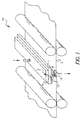
- Figure 1 shows a schematic diagram of an exemplary continuous ink jet print head and nozzle array as a print medium (e.g. paper) rolls under the ink jet print head.
- a print medium e.g. paper
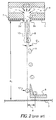
- Figure 2 is a cross-sectional view of one nozzle tip from a prior art nozzle array showing d 1 (distance to print medium) and ⁇ 1 (angle of deflection).
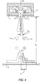
- Figure 3 shows a top view directly into a nozzle with an asymmetric heater surrounding the nozzle.
- Figure 4 is a cross-sectional view of one nozzle tip from one embodiment of the present invention showing d 2 and ⁇ 2 .
- Figure 5 is a cross-sectional view of one nozzle tip from a preferred embodiment of the present invention showing d 3 and ⁇ 3 .
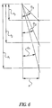
- Figure 6 is a graph illustrating the relationships between d 1 - d 3 , ⁇ 1 - ⁇ 3 , and A.
- a continuous ink jet printer system is generally shown at 10.
- the print head 1 from which extends an array of nozzle heaters 2, houses heater control circuits (not shown) which process signals to an ink pressure regulator (not shown).
- Heater control circuits read data from the image memory, and send time-sequenced electrical pulses to the array of nozzle heaters 2. These pulses are applied at an appropriate time, and to the appropriate nozzle, so that drops formed from a continuous ink jet stream will form spots on a recording medium 3, in the appropriate position designated by the data sent from the image memory. Pressurized ink travels from an ink reservoir (not shown) to an ink delivery channel 4 and through nozzle array 2 onto either the recording medium 3 or the gutter 9.
- ink delivery channel 4 shows arrows 5 that depict a substantially vertical flow pattern of ink headed into nozzle bore 6.
- wall 7 which serves, inter alia, to insulate the ink in the channel 4 from heat generated in the nozzle heater 2a/2a'.
- Thick wall 7 may also be referred to as the "orifice membrane.”
- An ink stream 8 forms as a meniscus of ink initially leaving the nozzle 2a/2a'. At a distance below the nozzle 2a/2a' ink stream 8 breaks into a plurality of drops 11.
- FIG 3 is an expanded bottom view of heater 2a/2a' showing the line 2-2, along which line the Figure 2 cross-sectional illustration is viewed.
- Heater 2a/2a' can be seen to have two sections (sections 2a and 2a'). Each section covers approximately one half of the nozzle bore opening 6.
- heater sections can vary in number and sectional design.
- One section provides a common connection G, and isolated connection P. The other has G' and P' respectively.
- Asymmetrical application of heat merely means applying electrical current to one or the other section of the heater independently. By so doing, the heat will deflect the ink stream 8, and deflect the drops 11, away from the particular source of the heat.
- the ink drops 11 are deflected at an angle ⁇ 1 (in Figure 2) and will travel a vertical distance d 1 onto recording media 3 from the print head.
- ⁇ 1 in Figure 2
- A distance defines the space between where the deflection angle ⁇ 1 would place the deflected drops 11 on the recording media (or a catcher) and where the drops 12 would have landed without deflection.
- the stream deflects in a direction anyway from the application of heat.
- the ink gutter 9 is configured to catch deflected ink droplets 11 while allowing undeflected drop 12 to reach a recording medium.
- An alternative embodiment of the present invention could reorient ink gutter (“catcher") 9 to be placed so as to catch undeflected drops 12 while allowing deflected drops 11 to reach the recording medium.
- the ink in the delivery channel emanates from a pressurized reservoir (not shown), leaving the ink in the channel under pressure.
- a pressurized reservoir not shown
- the ink pressure suitable for optimal operation would depend upon a number of factors, particularly geometry and thermal properties of the nozzles and thermal properties of the ink.
- a constant pressure can be achieved by employing an ink pressure regulator (not shown).
- the lateral course of ink flow patterns 5 in the ink delivery channel 4 are enhanced by, a geometric obstruction 20, placed in the delivery channel 4, just below the nozzle bore 6.
- This lateral flow enhancing obstruction 20 can be varied in size, shape and position, but serves to improve the deflection by many times x, based upon the lateralness of the flow and can therefore reduce the dependence upon ink properties (i.e. surface tension, density, viscosity, thermal conductivity, specific heat, etc.), nozzle geometry, and nozzle thermal properties while providing greater degree of control and improved image quality.
- the obstruction 20 has a lateral wall parallel to the reservoir side of wall 7, such as squares, cubes, rectangles, triangles, etc.
- the deflection enhancement may be seen by comparing for example the margins of difference between ⁇ 1 of Figure 2 and ⁇ 2 of Figure 4.
- This increased stream deflection enables improvements in drop placement (and thus image quality) by allowing the recording medium 3 to be placed closer to the print head 1 (d 2 is less than d 1 ) while preserving the other system level tolerances (i.e. spacing, alignment etc.) for example see distance A.
- the orifice membrane or wall 7 can also be thinner. We have found that a thinner wall provides additional enhancement in deflection which, in turn, serves to lessen the amount of heat needed per degree of the angle of deflection ⁇ 2 .
- Figure 6 shows the relationship of a constant drop placement A as distances to the print media d 1 , d 2 , and d 3 become less and less and as deflection angles ⁇ 1 , ⁇ 2 , and ⁇ 3 become increasingly larger.
Abstract
Description
- The present invention relates generally to the field of digitally controlled ink jet printing systems. It particularly relates to improving those systems that asymmetrically heat a continuous ink stream, in order to deflect the stream's flow between a non-print mode and a print mode.
- Ink jet printing is only one of many digitally controlled printing systems. Other digital printing systems include laser electrophotographic printers, LED electrophotographic printers, dot matrix impact printers, thermal paper printers, film recorders, thermal wax printers, and dye diffusion thermal transfer printers. Ink jet printers have become distinguished from the other digital printing systems because of the ink jet's non-impact nature, its low noise, its use of plain paper, and its avoidance of toner transfers and filing.
- The ink jet printers can be categorized as either drop-on-demand or continuous systems. However, it is the continuous ink jet system which has gained increasingly more recognition over the years. Major developments in continuous ink jet printing are as follows:
- Continuous ink jet printing itself dates back to at least 1929. See U.S. Patent 1,941,001 which issued to Hansell that year.
- U.S. Patent No. 3,373,437, which issued to Sweet et al. in March 1968, discloses an array of continuous ink jet nozzles wherein ink drops to be printed are selectively charged and deflected towards the recording medium. This technique is known as binary deflection continuous ink jet printing, and is used by several manufacturers, including Elmjet and Scitex.
- U.S. Patent No. 3,416,153, issued to Hertz et al. in December 1968. It discloses a method of achieving variable optical density of printed spots, in continuous ink jet printing. Therein the electrostatic dispersion of a charged drop stream serves to modulate the number of droplets which pass through a small aperture. This technique is used in ink jet printers manufactured by Iris.
- U.S. Patent No. 4,346,387, also issued to Hertz, but it issued in 1982. It discloses a method and apparatus for controlling the electrostatic charge on droplets. The droplets are formed by the breaking up of a pressurized liquid stream, at a drop formation point located within an electrostatic charging tunnel, having an electrical field. Drop formation is effected at a point in the electric field, corresponding to whatever predetermined charge is desired. In addition to charging tunnels, deflection plates are used to actually deflect the drops.
- Until recently, conventional continuous ink jet techniques all utilized, in one form or another, electrostatic charging tunnels that were placed close to the point where the drops are formed in a stream. In the tunnels, individual drops may be charged selectively. The selected drops are charged and deflected downstream by the presence of deflector plates that have a large potential difference between them. A gutter (sometimes referred to as a "catcher") is normally used to intercept the charged drops and establish a non-print mode, while the uncharged drops are free to strike the recording medium in a print mode as the ink stream is thereby deflected, between the "non-print" mode and the "print" mode.
- A continuous ink jet printer system has been suggested which renders the above-described electrostatic charging tunnels unnecessary. Additionally, it serves to better couple the functions of (1) droplet formation and (2) droplet deflection. The printer system comprises an ink delivery channel, a source of pressurized ink in communication with the ink delivery channel, and a nozzle having a bore which opens into the ink delivery channel, from which a continuous stream of ink flows. A droplet generator inside the nozzle causes the ink stream to break up into a plurality of droplets at a position spaced from the nozzle. The droplets are deflected by heat from a heater (in the nozzle bore) which heater has a selectively actuated section, i.e. a section associated with only a portion of the nozzle bore. Selective actuation of a particular heater section, at a particular portion of the nozzle bore produces what has been termed an asymmetrical application of heat to the stream. Alternating the sections can, in turn, alternate the direction in which this asymmetrical heat is applied and serves to thereby deflect the ink droplets, inter alia, between a "print" direction (onto a recording medium) and a "non-print" direction (back into a "catcher").
- Asymmetrically applied heat results in stream deflection, the magnitude of which depends upon several factors, e.g. the geometric and thermal properties of the nozzles, the quantity of applied heat, the pressure applied to, and the physical, chemical and thermal properties of the ink. Although solvent-based (particularly alcohol-based) inks have quite good deflection patterns, and achieve high image quality in asymmetrically heated continuous ink jet printers, water-based inks until now, have not. Water-based inks require a greater degree of deflection for comparable image quality than the asymmetric treatment, jet velocity, spacing, and alignment tolerances have in the past allowed. Accordingly, a means for enhancing the degree of deflection for such continuous ink jet systems, within system tolerances would represent a surprising but significant advancement in the art and satisfy an important need in the industry for water-based, and thus more environmentally friendly inks.
- It is therefore a principal object of the present invention to improve the magnitude of ink droplet deflection within continuous ink jet asymmetrically heated printing systems, without negating otherwise acceptable system tolerances.
- With the above object in view, the invention is defined by the several claims appended hereto.
- According to an aspect of the invention, lateral flow of ink entering the nozzle bore section of a continuous ink jet printer system is increased. The printer system is of the type employing asymmetrical heating for drop deflection. Said lateral flow is increased by imposing particular geometric obstructions at a position upstream from the nozzle bore entrance.
- Figure 1 shows a schematic diagram of an exemplary continuous ink jet print head and nozzle array as a print medium (e.g. paper) rolls under the ink jet print head.
- Figure 2 is a cross-sectional view of one nozzle tip from a prior art nozzle array showing d1 (distance to print medium) and 1 (angle of deflection).
- Figure 3 shows a top view directly into a nozzle with an asymmetric heater surrounding the nozzle.
- Figure 4 is a cross-sectional view of one nozzle tip from one embodiment of the present invention showing d2 and 2.
- Figure 5 is a cross-sectional view of one nozzle tip from a preferred embodiment of the present invention showing d3 and 3.
- Figure 6 is a graph illustrating the relationships between d1 - d3, 1 - 3, and A.
- The present description will be directed, in particular, to elements forming part of, or cooperating directly with, apparatus or processes of the present invention. It is to be understood that elements not specifically shown or described may take various forms well known to those skilled in the art.
- Referring to Figure 1, a continuous ink jet printer system is generally shown at 10. The
print head 1, from which extends an array ofnozzle heaters 2, houses heater control circuits (not shown) which process signals to an ink pressure regulator (not shown). - Heater control circuits read data from the image memory, and send time-sequenced electrical pulses to the array of
nozzle heaters 2. These pulses are applied at an appropriate time, and to the appropriate nozzle, so that drops formed from a continuous ink jet stream will form spots on arecording medium 3, in the appropriate position designated by the data sent from the image memory. Pressurized ink travels from an ink reservoir (not shown) to anink delivery channel 4 and throughnozzle array 2 onto either therecording medium 3 or thegutter 9. - Referring now to Figure 2, an enlarged cross-sectional view of a
single nozzle heater 2a/2a' from among thenozzle array 2 shown in Figure 1, is illustrated, as it is in the prior art. Note thatink delivery channel 4 showsarrows 5 that depict a substantially vertical flow pattern of ink headed intonozzle bore 6. There is a relatively thick wall 7 which serves, inter alia, to insulate the ink in thechannel 4 from heat generated in thenozzle heater 2a/2a'. Thick wall 7 may also be referred to as the "orifice membrane." Anink stream 8 forms as a meniscus of ink initially leaving thenozzle 2a/2a'. At a distance below thenozzle 2a/2a' ink stream 8 breaks into a plurality ofdrops 11. - Figure 3 is an expanded bottom view of
heater 2a/2a' showing the line 2-2, along which line the Figure 2 cross-sectional illustration is viewed.Heater 2a/2a' can be seen to have two sections (sections ink stream 8, and deflect thedrops 11, away from the particular source of the heat. For a given amount of heat, the ink drops 11 are deflected at an angle 1 (in Figure 2) and will travel a vertical distance d1 ontorecording media 3 from the print head. There also is a distance "A", which distance defines the space between where the deflection angle 1 would place the deflected drops 11 on the recording media (or a catcher) and where thedrops 12 would have landed without deflection. The stream deflects in a direction anyway from the application of heat. Theink gutter 9 is configured to catch deflectedink droplets 11 while allowingundeflected drop 12 to reach a recording medium. An alternative embodiment of the present invention could reorient ink gutter ("catcher") 9 to be placed so as to catch undeflected drops 12 while allowing deflected drops 11 to reach the recording medium. - The ink in the delivery channel emanates from a pressurized reservoir (not shown), leaving the ink in the channel under pressure. In the past the ink pressure suitable for optimal operation would depend upon a number of factors, particularly geometry and thermal properties of the nozzles and thermal properties of the ink. A constant pressure can be achieved by employing an ink pressure regulator (not shown).
- Referring to Figure 4, in the operation of the present invention, the lateral course of
ink flow patterns 5 in theink delivery channel 4, are enhanced by, ageometric obstruction 20, placed in thedelivery channel 4, just below thenozzle bore 6. This lateralflow enhancing obstruction 20 can be varied in size, shape and position, but serves to improve the deflection by many times x, based upon the lateralness of the flow and can therefore reduce the dependence upon ink properties (i.e. surface tension, density, viscosity, thermal conductivity, specific heat, etc.), nozzle geometry, and nozzle thermal properties while providing greater degree of control and improved image quality. Preferably theobstruction 20 has a lateral wall parallel to the reservoir side of wall 7, such as squares, cubes, rectangles, triangles, etc. The deflection enhancement may be seen by comparing for example the margins of difference between 1 of Figure 2 and 2 of Figure 4. This increased stream deflection enables improvements in drop placement (and thus image quality) by allowing therecording medium 3 to be placed closer to the print head 1 (d2 is less than d1) while preserving the other system level tolerances (i.e. spacing, alignment etc.) for example see distance A. The orifice membrane or wall 7 can also be thinner. We have found that a thinner wall provides additional enhancement in deflection which, in turn, serves to lessen the amount of heat needed per degree of the angle of deflection 2. - Referring now to Figure 5 drop placement and thus image quality can be even further enhanced by an
obstruction 20 which provides almost total lateral flow at the entrance tonozzle bore 6. The distance d3 to print medium 3 is again lessened per degree of heat because deflection angle 3 can be increased per unit temperature. - Figure 6 shows the relationship of a constant drop placement A as distances to the print media d1, d2, and d3 become less and less and as deflection angles 1, 2, and 3 become increasingly larger. As a consequence of enhanced lateral flow, the ability to miniaturize the printer's structural dimensions while enhancing image size and enhancing image detail is achieved.
Claims (8)
- Apparatus for controlling ink in a continuous ink jet printer in which a continuous stream of ink (8) is emitted from a nozzle, said apparatus comprising:an ink delivery channel (4) having disposed therein a geometric obstruction (20) to include lateral flow of the ink at a predetermined magnitude;a source of pressurized ink;the source of pressurized ink communicating with the ink delivery channel;a nozzle bore (6) which opens into the ink delivery to establish a continuous flow of ink in a stream, the nozzle bore defining a nozzle bore perimeter; anda nozzle heater having a selectively actuated section (2a, 2a') associated with only a portion of the nozzle bore perimeter, whereby actuation of the heater section produces an asymmetric application of heat to the stream which controls the stream direction thereby enabling the stream to deflect in a direction away from the applied heat, and which deflection is in a magnitude proportional to the lateral flow magnitude.
- The apparatus of claim 1, wherein the geometric obstruction has a lateral wall parallel to the orifice membrane wall.
- The apparatus of claim 2, wherein the geometric obstruction's lateral wall has a length which is proportional to the magnitude of the lateral flow.
- The apparatus of claim 2, wherein the geometric obstruction is selected from the group of geometrics consisting of rectangular, square, cubical and triangular.
- Apparatus of claim 1, wherein the magnitude of deflection is enhanced as the orifice membrane wall is reduced in thickness.
- A method for improving the image quality of the continuous ink jet printer of claim 1, said method comprising increasing the lateral ink flow in order to increase the magnitude of deflection.
- The method of claim 6, further comprising reducing the orifice membrane wall's thickness in order to improve deflection.
- The apparatus of claim 1, further comprising a distance (d1, d2, d3) between the nozzle heater and a recording medium (3) onto which the ink prints, said distance being less than such distance for ink jet printers having no geometric obstructions to induce lateral flow.
Applications Claiming Priority (2)
| Application Number | Priority Date | Filing Date | Title |
|---|---|---|---|
| US09/470,638 US6497510B1 (en) | 1999-12-22 | 1999-12-22 | Deflection enhancement for continuous ink jet printers |
| US470638 | 1999-12-22 |
Publications (3)
| Publication Number | Publication Date |
|---|---|
| EP1110732A2 true EP1110732A2 (en) | 2001-06-27 |
| EP1110732A3 EP1110732A3 (en) | 2002-06-12 |
| EP1110732B1 EP1110732B1 (en) | 2006-04-26 |
Family
ID=23868395
Family Applications (1)
| Application Number | Title | Priority Date | Filing Date |
|---|---|---|---|
| EP00204448A Expired - Lifetime EP1110732B1 (en) | 1999-12-22 | 2000-12-11 | Deflection enhancement for continuous ink jet printers |
Country Status (4)
| Country | Link |
|---|---|
| US (2) | US6497510B1 (en) |
| EP (1) | EP1110732B1 (en) |
| JP (1) | JP4594516B2 (en) |
| DE (1) | DE60027526T2 (en) |
Cited By (4)
| Publication number | Priority date | Publication date | Assignee | Title |
|---|---|---|---|---|
| EP1219427A2 (en) | 2000-12-29 | 2002-07-03 | Eastman Kodak Company | Incorporation of supplementary heaters in the ink channels of cmos/mems integrated ink jet print head and method of forming same |
| EP1219425A2 (en) | 2000-12-29 | 2002-07-03 | Eastman Kodak Company | Cmos/mems integrated ink jet print head with oxide based lateral flow nozzle architecture and method of forming same |
| EP1219424A3 (en) * | 2000-12-29 | 2003-05-14 | Eastman Kodak Company | Cmos/mems integrated ink jet print head with silicon based lateral flow nozzle architecture and method of forming same |
| EP1452315A3 (en) * | 2003-02-27 | 2005-08-31 | Sony Corporation | Liquid discharge apparatus and method for discharging liquid |
Families Citing this family (27)
| Publication number | Priority date | Publication date | Assignee | Title |
|---|---|---|---|---|
| US6497510B1 (en) * | 1999-12-22 | 2002-12-24 | Eastman Kodak Company | Deflection enhancement for continuous ink jet printers |
| US6986566B2 (en) | 1999-12-22 | 2006-01-17 | Eastman Kodak Company | Liquid emission device |
| US6746108B1 (en) * | 2002-11-18 | 2004-06-08 | Eastman Kodak Company | Method and apparatus for printing ink droplets that strike print media substantially perpendicularly |
| JP3805756B2 (en) * | 2003-03-28 | 2006-08-09 | 株式会社東芝 | Inkjet recording device |
| US7051654B2 (en) * | 2003-05-30 | 2006-05-30 | Clemson University | Ink-jet printing of viable cells |
| US20060100308A1 (en) * | 2004-11-09 | 2006-05-11 | Eastman Kodak Company | Overcoat composition for printed images |
| US7897655B2 (en) * | 2004-11-09 | 2011-03-01 | Eastman Kodak Company | Ink jet ink composition |
| US7549298B2 (en) * | 2004-12-04 | 2009-06-23 | Hewlett-Packard Development Company, L.P. | Spray cooling with spray deflection |
| JP2007050584A (en) * | 2005-08-17 | 2007-03-01 | Fujifilm Holdings Corp | Mist jet head and image forming apparatus |
| US7731341B2 (en) | 2005-09-07 | 2010-06-08 | Eastman Kodak Company | Continuous fluid jet ejector with anisotropically etched fluid chambers |
| US7785496B1 (en) | 2007-01-26 | 2010-08-31 | Clemson University Research Foundation | Electrochromic inks including conducting polymer colloidal nanocomposites, devices including the electrochromic inks and methods of forming same |
| US7758155B2 (en) * | 2007-05-15 | 2010-07-20 | Eastman Kodak Company | Monolithic printhead with multiple rows of inkjet orifices |
| US20080284835A1 (en) * | 2007-05-15 | 2008-11-20 | Panchawagh Hrishikesh V | Integral, micromachined gutter for inkjet printhead |
| US20090033727A1 (en) * | 2007-07-31 | 2009-02-05 | Anagnostopoulos Constantine N | Lateral flow device printhead with internal gutter |
| US8585179B2 (en) * | 2008-03-28 | 2013-11-19 | Eastman Kodak Company | Fluid flow in microfluidic devices |
| US8398210B2 (en) | 2011-04-19 | 2013-03-19 | Eastman Kodak Company | Continuous ejection system including compliant membrane transducer |
| US8529021B2 (en) | 2011-04-19 | 2013-09-10 | Eastman Kodak Company | Continuous liquid ejection using compliant membrane transducer |
| AU2012286817A1 (en) | 2011-07-26 | 2014-02-13 | The Curators Of The University Of Missouri | Engineered comestible meat |
| WO2015038988A1 (en) | 2013-09-13 | 2015-03-19 | Modern Meadow, Inc. | Edible and animal-product-free microcarriers for engineered meat |
| CA2938156C (en) | 2014-02-05 | 2022-05-10 | Modern Meadow, Inc. | Dried food products formed from cultured muscle cells |
| JP2015214036A (en) * | 2014-05-08 | 2015-12-03 | 株式会社日立産機システム | Ink jet recorder |
| ES2842501T5 (en) | 2015-09-21 | 2023-04-13 | Modern Meadow Inc | Fiber Reinforced Fabric Composite Materials |
| KR20170096093A (en) | 2016-02-15 | 2017-08-23 | 브렌던 패트릭 퍼셀 | Composite biofabricated material |
| FR3065394B1 (en) | 2017-04-21 | 2019-07-05 | Dover Europe Sàrl | METHOD AND DEVICE FOR HYDRODYNAMIC INKJET DEFLECTION |
| AU2018253595A1 (en) | 2017-11-13 | 2019-05-30 | Modern Meadow, Inc. | Biofabricated leather articles having zonal properties |
| EP3704202A4 (en) | 2019-01-17 | 2020-12-16 | Modern Meadow, Inc. | Layered collagen materials and methods of making the same |
| US11557895B2 (en) | 2021-04-30 | 2023-01-17 | Taiwan Semiconductor Manufacturing Company, Ltd | Power clamp |
Citations (4)
| Publication number | Priority date | Publication date | Assignee | Title |
|---|---|---|---|---|
| US1941001A (en) | 1929-01-19 | 1933-12-26 | Rca Corp | Recorder |
| US3373437A (en) | 1964-03-25 | 1968-03-12 | Richard G. Sweet | Fluid droplet recorder with a plurality of jets |
| US3416153A (en) | 1965-10-08 | 1968-12-10 | Hertz | Ink jet recorder |
| US4346387A (en) | 1979-12-07 | 1982-08-24 | Hertz Carl H | Method and apparatus for controlling the electric charge on droplets and ink-jet recorder incorporating the same |
Family Cites Families (15)
| Publication number | Priority date | Publication date | Assignee | Title |
|---|---|---|---|---|
| NL6818587A (en) | 1967-12-28 | 1969-07-01 | ||
| US3878519A (en) | 1974-01-31 | 1975-04-15 | Ibm | Method and apparatus for synchronizing droplet formation in a liquid stream |
| US4812859A (en) | 1987-09-17 | 1989-03-14 | Hewlett-Packard Company | Multi-chamber ink jet recording head for color use |
| JPH0469249A (en) * | 1990-07-11 | 1992-03-04 | Tokyo Electric Co Ltd | Ink jet printer head |
| US5068006A (en) | 1990-09-04 | 1991-11-26 | Xerox Corporation | Thermal ink jet printhead with pre-diced nozzle face and method of fabrication therefor |
| AU657720B2 (en) | 1991-01-30 | 1995-03-23 | Canon Kabushiki Kaisha | A bubblejet image reproducing apparatus |
| JP3114776B2 (en) * | 1992-06-23 | 2000-12-04 | セイコーエプソン株式会社 | Printer using inkjet line recording head |
| DE69324166T2 (en) * | 1993-01-06 | 1999-09-02 | Seiko Epson Corp | INK JET PRINT HEAD |
| JP3592780B2 (en) * | 1995-02-22 | 2004-11-24 | 富士写真フイルム株式会社 | Liquid injection device |
| DE69706751T2 (en) * | 1996-04-30 | 2002-07-04 | Scitex Digital Printing Inc | Droplet generator fed at the top |
| US6509917B1 (en) | 1997-10-17 | 2003-01-21 | Eastman Kodak Company | Continuous ink jet printer with binary electrostatic deflection |
| US6079821A (en) * | 1997-10-17 | 2000-06-27 | Eastman Kodak Company | Continuous ink jet printer with asymmetric heating drop deflection |
| US5966154A (en) * | 1997-10-17 | 1999-10-12 | Eastman Kodak Company | Graphic arts printing plate production by a continuous jet drop printing with asymmetric heating drop deflection |
| US6497510B1 (en) * | 1999-12-22 | 2002-12-24 | Eastman Kodak Company | Deflection enhancement for continuous ink jet printers |
| US6382782B1 (en) | 2000-12-29 | 2002-05-07 | Eastman Kodak Company | CMOS/MEMS integrated ink jet print head with oxide based lateral flow nozzle architecture and method of forming same |
-
1999
- 1999-12-22 US US09/470,638 patent/US6497510B1/en not_active Expired - Lifetime
-
2000
- 2000-12-11 DE DE60027526T patent/DE60027526T2/en not_active Expired - Lifetime
- 2000-12-11 EP EP00204448A patent/EP1110732B1/en not_active Expired - Lifetime
- 2000-12-21 JP JP2000389103A patent/JP4594516B2/en not_active Expired - Fee Related
-
2002
- 2002-10-18 US US10/273,916 patent/US6761437B2/en not_active Expired - Fee Related
Patent Citations (4)
| Publication number | Priority date | Publication date | Assignee | Title |
|---|---|---|---|---|
| US1941001A (en) | 1929-01-19 | 1933-12-26 | Rca Corp | Recorder |
| US3373437A (en) | 1964-03-25 | 1968-03-12 | Richard G. Sweet | Fluid droplet recorder with a plurality of jets |
| US3416153A (en) | 1965-10-08 | 1968-12-10 | Hertz | Ink jet recorder |
| US4346387A (en) | 1979-12-07 | 1982-08-24 | Hertz Carl H | Method and apparatus for controlling the electric charge on droplets and ink-jet recorder incorporating the same |
Cited By (10)
| Publication number | Priority date | Publication date | Assignee | Title |
|---|---|---|---|---|
| EP1219427A2 (en) | 2000-12-29 | 2002-07-03 | Eastman Kodak Company | Incorporation of supplementary heaters in the ink channels of cmos/mems integrated ink jet print head and method of forming same |
| EP1219425A2 (en) | 2000-12-29 | 2002-07-03 | Eastman Kodak Company | Cmos/mems integrated ink jet print head with oxide based lateral flow nozzle architecture and method of forming same |
| EP1219424A3 (en) * | 2000-12-29 | 2003-05-14 | Eastman Kodak Company | Cmos/mems integrated ink jet print head with silicon based lateral flow nozzle architecture and method of forming same |
| US6780339B2 (en) | 2000-12-29 | 2004-08-24 | Eastman Kodak Company | CMOS/MEMS integrated ink jet print head with oxide based lateral flow nozzle architecture and method of forming same |
| EP1452315A3 (en) * | 2003-02-27 | 2005-08-31 | Sony Corporation | Liquid discharge apparatus and method for discharging liquid |
| US7306309B2 (en) | 2003-02-27 | 2007-12-11 | Sony Corporation | Liquid discharge apparatus and method for discharging liquid |
| EP1932674A2 (en) * | 2003-02-27 | 2008-06-18 | Sony Corporation | Liquid discharge apparatus and method for discharging liquid |
| EP1932674A3 (en) * | 2003-02-27 | 2008-11-26 | Sony Corporation | Liquid discharge apparatus and method for discharging liquid |
| EP1932673A3 (en) * | 2003-02-27 | 2008-11-26 | Sony Corporation | Liquid discharge apparatus and method for discharging liquid |
| CN101254694B (en) * | 2003-02-27 | 2013-09-18 | 索尼株式会社 | Liquid discharge apparatus and method for discharging liquid |
Also Published As
| Publication number | Publication date |
|---|---|
| EP1110732A3 (en) | 2002-06-12 |
| JP4594516B2 (en) | 2010-12-08 |
| US20030043223A1 (en) | 2003-03-06 |
| DE60027526T2 (en) | 2006-11-23 |
| EP1110732B1 (en) | 2006-04-26 |
| JP2001179983A (en) | 2001-07-03 |
| DE60027526D1 (en) | 2006-06-01 |
| US6497510B1 (en) | 2002-12-24 |
| US6761437B2 (en) | 2004-07-13 |
Similar Documents
| Publication | Publication Date | Title |
|---|---|---|
| EP1110732B1 (en) | Deflection enhancement for continuous ink jet printers | |
| US6509917B1 (en) | Continuous ink jet printer with binary electrostatic deflection | |
| EP0911168B1 (en) | Continuous ink jet printer with asymmetric heating drop deflection | |
| US6746108B1 (en) | Method and apparatus for printing ink droplets that strike print media substantially perpendicularly | |
| US6217163B1 (en) | Continuous ink jet print head having multi-segment heaters | |
| EP1108542B1 (en) | Continuous ink jet system having non-circular orifices | |
| EP1219428A2 (en) | Ink jet apparatus having amplified asymmetric heating drop deflection | |
| EP0911165B1 (en) | Continuous ink jet printer with variable contact drop deflection | |
| EP1112847B1 (en) | Continuous ink jet printer with a notch deflector | |
| US6588890B1 (en) | Continuous inkjet printer with heat actuated microvalves for controlling the direction of delivered ink | |
| EP1193066B1 (en) | Steering fluid device and method for increasing the angle of deflection of ink droplets generated by an asymmetric heat-type inkjet printer | |
| US6254225B1 (en) | Continuous ink jet printer with asymmetric heating drop deflection | |
| US6508542B2 (en) | Ink drop deflection amplifier mechanism and method of increasing ink drop divergence | |
| US7364277B2 (en) | Apparatus and method of controlling droplet trajectory | |
| US6986566B2 (en) | Liquid emission device | |
| EP0911166A2 (en) | Continuous ink jet printer with electrostatic drop deflection | |
| US6578955B2 (en) | Continuous inkjet printer with actuatable valves for controlling the direction of delivered ink | |
| US6402305B1 (en) | Method for preventing ink drop misdirection in an asymmetric heat-type ink jet printer |
Legal Events
| Date | Code | Title | Description |
|---|---|---|---|
| PUAI | Public reference made under article 153(3) epc to a published international application that has entered the european phase |
Free format text: ORIGINAL CODE: 0009012 |
|
| AK | Designated contracting states |
Kind code of ref document: A2 Designated state(s): AT BE CH CY DE DK ES FI FR GB GR IE IT LI LU MC NL PT SE TR |
|
| AX | Request for extension of the european patent |
Free format text: AL;LT;LV;MK;RO;SI |
|
| PUAL | Search report despatched |
Free format text: ORIGINAL CODE: 0009013 |
|
| AK | Designated contracting states |
Kind code of ref document: A3 Designated state(s): AT BE CH CY DE DK ES FI FR GB GR IE IT LI LU MC NL PT SE TR |
|
| AX | Request for extension of the european patent |
Free format text: AL;LT;LV;MK;RO;SI |
|
| 17P | Request for examination filed |
Effective date: 20021113 |
|
| AKX | Designation fees paid |
Designated state(s): DE FR GB |
|
| 17Q | First examination report despatched |
Effective date: 20030214 |
|
| GRAP | Despatch of communication of intention to grant a patent |
Free format text: ORIGINAL CODE: EPIDOSNIGR1 |
|
| GRAS | Grant fee paid |
Free format text: ORIGINAL CODE: EPIDOSNIGR3 |
|
| GRAA | (expected) grant |
Free format text: ORIGINAL CODE: 0009210 |
|
| AK | Designated contracting states |
Kind code of ref document: B1 Designated state(s): DE FR GB |
|
| REG | Reference to a national code |
Ref country code: GB Ref legal event code: FG4D |
|
| REF | Corresponds to: |
Ref document number: 60027526 Country of ref document: DE Date of ref document: 20060601 Kind code of ref document: P |
|
| ET | Fr: translation filed | ||
| PLBE | No opposition filed within time limit |
Free format text: ORIGINAL CODE: 0009261 |
|
| STAA | Information on the status of an ep patent application or granted ep patent |
Free format text: STATUS: NO OPPOSITION FILED WITHIN TIME LIMIT |
|
| 26N | No opposition filed |
Effective date: 20070129 |
|
| PGFP | Annual fee paid to national office [announced via postgrant information from national office to epo] |
Ref country code: GB Payment date: 20101123 Year of fee payment: 11 |
|
| PGFP | Annual fee paid to national office [announced via postgrant information from national office to epo] |
Ref country code: FR Payment date: 20111205 Year of fee payment: 12 |
|
| PGFP | Annual fee paid to national office [announced via postgrant information from national office to epo] |
Ref country code: DE Payment date: 20111230 Year of fee payment: 12 |
|
| GBPC | Gb: european patent ceased through non-payment of renewal fee |
Effective date: 20121211 |
|
| REG | Reference to a national code |
Ref country code: FR Ref legal event code: ST Effective date: 20130830 |
|
| REG | Reference to a national code |
Ref country code: DE Ref legal event code: R119 Ref document number: 60027526 Country of ref document: DE Effective date: 20130702 |
|
| PG25 | Lapsed in a contracting state [announced via postgrant information from national office to epo] |
Ref country code: DE Free format text: LAPSE BECAUSE OF NON-PAYMENT OF DUE FEES Effective date: 20130702 |
|
| PG25 | Lapsed in a contracting state [announced via postgrant information from national office to epo] |
Ref country code: FR Free format text: LAPSE BECAUSE OF NON-PAYMENT OF DUE FEES Effective date: 20130102 Ref country code: GB Free format text: LAPSE BECAUSE OF NON-PAYMENT OF DUE FEES Effective date: 20121211 |