EP1111666A2 - Process for making structures on integrated circuits - Google Patents
Process for making structures on integrated circuits Download PDFInfo
- Publication number
- EP1111666A2 EP1111666A2 EP00890355A EP00890355A EP1111666A2 EP 1111666 A2 EP1111666 A2 EP 1111666A2 EP 00890355 A EP00890355 A EP 00890355A EP 00890355 A EP00890355 A EP 00890355A EP 1111666 A2 EP1111666 A2 EP 1111666A2
- Authority
- EP
- European Patent Office
- Prior art keywords
- masking structure
- auxiliary layer
- masking
- layer
- planarization
- Prior art date
- Legal status (The legal status is an assumption and is not a legal conclusion. Google has not performed a legal analysis and makes no representation as to the accuracy of the status listed.)
- Withdrawn
Links
Images

Classifications
-
- H—ELECTRICITY
- H01—ELECTRIC ELEMENTS
- H01L—SEMICONDUCTOR DEVICES NOT COVERED BY CLASS H10
- H01L21/00—Processes or apparatus adapted for the manufacture or treatment of semiconductor or solid state devices or of parts thereof
- H01L21/02—Manufacture or treatment of semiconductor devices or of parts thereof
- H01L21/04—Manufacture or treatment of semiconductor devices or of parts thereof the devices having at least one potential-jump barrier or surface barrier, e.g. PN junction, depletion layer or carrier concentration layer
- H01L21/18—Manufacture or treatment of semiconductor devices or of parts thereof the devices having at least one potential-jump barrier or surface barrier, e.g. PN junction, depletion layer or carrier concentration layer the devices having semiconductor bodies comprising elements of Group IV of the Periodic System or AIIIBV compounds with or without impurities, e.g. doping materials
- H01L21/30—Treatment of semiconductor bodies using processes or apparatus not provided for in groups H01L21/20 - H01L21/26
- H01L21/31—Treatment of semiconductor bodies using processes or apparatus not provided for in groups H01L21/20 - H01L21/26 to form insulating layers thereon, e.g. for masking or by using photolithographic techniques; After treatment of these layers; Selection of materials for these layers
- H01L21/3105—After-treatment
- H01L21/311—Etching the insulating layers by chemical or physical means
- H01L21/31144—Etching the insulating layers by chemical or physical means using masks
-
- H—ELECTRICITY
- H01—ELECTRIC ELEMENTS
- H01L—SEMICONDUCTOR DEVICES NOT COVERED BY CLASS H10
- H01L21/00—Processes or apparatus adapted for the manufacture or treatment of semiconductor or solid state devices or of parts thereof
- H01L21/02—Manufacture or treatment of semiconductor devices or of parts thereof
- H01L21/027—Making masks on semiconductor bodies for further photolithographic processing not provided for in group H01L21/18 or H01L21/34
- H01L21/033—Making masks on semiconductor bodies for further photolithographic processing not provided for in group H01L21/18 or H01L21/34 comprising inorganic layers
- H01L21/0334—Making masks on semiconductor bodies for further photolithographic processing not provided for in group H01L21/18 or H01L21/34 comprising inorganic layers characterised by their size, orientation, disposition, behaviour, shape, in horizontal or vertical plane
- H01L21/0337—Making masks on semiconductor bodies for further photolithographic processing not provided for in group H01L21/18 or H01L21/34 comprising inorganic layers characterised by their size, orientation, disposition, behaviour, shape, in horizontal or vertical plane characterised by the process involved to create the mask, e.g. lift-off masks, sidewalls, or to modify the mask, e.g. pre-treatment, post-treatment
-
- H—ELECTRICITY
- H01—ELECTRIC ELEMENTS
- H01L—SEMICONDUCTOR DEVICES NOT COVERED BY CLASS H10
- H01L21/00—Processes or apparatus adapted for the manufacture or treatment of semiconductor or solid state devices or of parts thereof
- H01L21/02—Manufacture or treatment of semiconductor devices or of parts thereof
- H01L21/04—Manufacture or treatment of semiconductor devices or of parts thereof the devices having at least one potential-jump barrier or surface barrier, e.g. PN junction, depletion layer or carrier concentration layer
- H01L21/18—Manufacture or treatment of semiconductor devices or of parts thereof the devices having at least one potential-jump barrier or surface barrier, e.g. PN junction, depletion layer or carrier concentration layer the devices having semiconductor bodies comprising elements of Group IV of the Periodic System or AIIIBV compounds with or without impurities, e.g. doping materials
- H01L21/30—Treatment of semiconductor bodies using processes or apparatus not provided for in groups H01L21/20 - H01L21/26
- H01L21/302—Treatment of semiconductor bodies using processes or apparatus not provided for in groups H01L21/20 - H01L21/26 to change their surface-physical characteristics or shape, e.g. etching, polishing, cutting
- H01L21/306—Chemical or electrical treatment, e.g. electrolytic etching
- H01L21/308—Chemical or electrical treatment, e.g. electrolytic etching using masks
- H01L21/3083—Chemical or electrical treatment, e.g. electrolytic etching using masks characterised by their size, orientation, disposition, behaviour, shape, in horizontal or vertical plane
- H01L21/3086—Chemical or electrical treatment, e.g. electrolytic etching using masks characterised by their size, orientation, disposition, behaviour, shape, in horizontal or vertical plane characterised by the process involved to create the mask, e.g. lift-off masks, sidewalls, or to modify the mask, e.g. pre-treatment, post-treatment
-
- H—ELECTRICITY
- H01—ELECTRIC ELEMENTS
- H01L—SEMICONDUCTOR DEVICES NOT COVERED BY CLASS H10
- H01L21/00—Processes or apparatus adapted for the manufacture or treatment of semiconductor or solid state devices or of parts thereof
- H01L21/02—Manufacture or treatment of semiconductor devices or of parts thereof
- H01L21/04—Manufacture or treatment of semiconductor devices or of parts thereof the devices having at least one potential-jump barrier or surface barrier, e.g. PN junction, depletion layer or carrier concentration layer
- H01L21/18—Manufacture or treatment of semiconductor devices or of parts thereof the devices having at least one potential-jump barrier or surface barrier, e.g. PN junction, depletion layer or carrier concentration layer the devices having semiconductor bodies comprising elements of Group IV of the Periodic System or AIIIBV compounds with or without impurities, e.g. doping materials
- H01L21/30—Treatment of semiconductor bodies using processes or apparatus not provided for in groups H01L21/20 - H01L21/26
- H01L21/31—Treatment of semiconductor bodies using processes or apparatus not provided for in groups H01L21/20 - H01L21/26 to form insulating layers thereon, e.g. for masking or by using photolithographic techniques; After treatment of these layers; Selection of materials for these layers
- H01L21/3205—Deposition of non-insulating-, e.g. conductive- or resistive-, layers on insulating layers; After-treatment of these layers
- H01L21/321—After treatment
- H01L21/3213—Physical or chemical etching of the layers, e.g. to produce a patterned layer from a pre-deposited extensive layer
- H01L21/32139—Physical or chemical etching of the layers, e.g. to produce a patterned layer from a pre-deposited extensive layer using masks
Definitions
- the invention relates to a method for producing structures in chips, in which a sequence of structuring steps self-adjusting is applied.
- each individual structuring step is hereby using a mask, each time one Photo mask must be precisely aligned.
- the photo mask exactly on the already existing structure to be aligned with whatever the structures that are becoming smaller in semiconductor production place high demands to the adjustment accuracy.
- the process flow should be kept as simple as possible to keep the manufacturing costs as low as possible.
- the present invention aims to be a simple method to create structures in chips at which aligning the photo masks and the associated Adjustment problems are avoided and which for the production of small structures.
- the Structuring steps are self-adjusting and a simple process flow can be guaranteed.
- the method according to the invention exists to achieve this object essentially in that by structuring a first auxiliary layer applied to a support after a first Masking a first masking structure is formed, which protrude at least one over the surface of the carrier Sub-area has that subsequently another Structuring step, for example by etching, implanting or CVD (chemical vapor deposition), using the previously produced first masking structure made as a mask and that then the first masking structure for training a second masking structure thereby inverted is that at least a second on the first masking structure Auxiliary layer applied, at least the structure thus formed partially removed and the resulting first auxiliary layer is selectively removed, whereupon the second masking structure as a mask for a further structuring step is used.
- subsequently another Structuring step for example by etching, implanting or CVD (chemical vapor deposition)
- a first auxiliary layer applied to a support after a a masking structure is formed for the first masking which protrude at least one over the surface of the carrier Sub-area is the prerequisite for this created one in subsequent structuring steps Inversion of the structure in such a way that the im first projecting sub-area formed is removed and remaining parts each as reference elements for the Self-adjustment take effect.
- Masking structure can be produced in that the first masking structure is inverted.
- the inversion takes place hiebei according to the invention in that the first masking structure when a second auxiliary layer is applied and subsequently carried out an at least partial removal becomes.
- the removal can in principle be carried out by planarization, such a planarization so far only for training of flat surface structures, but not, as according to the invention proposed to use for inverting a structure has been.
- planarization which, as one preferred further development corresponds, for example by a chemical-mechanical grinding process and / or etching back process can be made, a new structure after the partial Material removal of the higher parts of the chip formed, in which the first masking structure, insofar as it is still left, is again exposed and subsequently is selectively removed.
- the remaining parts of the second Auxiliary layer form a second masking structure, which as Mask is used for the further structuring steps.
- this sequence of structuring steps results in where as an essential step an inversion the structure using planarization techniques is a particularly simple procedure for training of small structures and especially for example to form a large number of semiconductor switching or Components, such as bipolar transistors, on the Surface of the chip, so that a higher component density at the same time increased precision of the respective layer boundaries can be achieved.
- the removal is preferably carried out by a chemical-mechanical grinding or by etching back.
- etchback methods for the Planarization to invert the structure is advantageous proceeded that in addition to the first masking structure to the second auxiliary layer a planarization layer from one Material is applied that has good planarization properties owns.
- the planarization layer forms in lower ones Areas a thicker layer than over the higher chip parts. Now you can etch evenly with an ideal one Etch rate for the planarization layer and the higher ones Structures, so the topography of the planarized is transferred Layer surface on the chip surface. That way ensures that the desired inversion of the structure with high precision is achieved.
- the procedure according to the invention is such that the second Auxiliary layer and possibly not the planarization layer becomes planarizing.
- a non-planarizing etching has here the preference that the material take directed and in the first place Line is vertical, such a non-planarizing Etching especially for the formation of spacers and therefore especially for the purposes of self-adjustment Advantage is. It is therefore preferred in the context of the method proceeded so that the first and / or the second A masking structure is applied, which then anisotropic to form a spacer is etched.
- the strength of the first and / or is applied to the second masking structure in consequently ensures the precision of the adjustment, since the remaining spacers a thickness towards the surface have measured, which is essentially the strength of the applied layer corresponds.
- the procedure according to the invention is such that the first Masking structure made of silicon nitride, so that in the Follow a simple removal of this layer with conventional ones Methods, for example using hot phosphoric acid.
- the second masking structure made of silicon oxide is also advantageous trained and the planarization layer from one organic polymer.
- the removal of organic polymers can by thermal processes and for example also by plasma etching take place, layers of silicon oxide or polycrystalline Silicon in such a selective removal step cannot be changed.
- the second auxiliary layer can advantageously also consist of an organic one Polymer exist, in which case the selective Removal of this planarization layer from the rest Layers is also guaranteed.
- a carrier material that does not have any etching selectivity compared to layers to be applied subsequently has, is advantageously carried out so that the carrier itself a third auxiliary layer is made of a material with good Etching selectivity to the first and second masking structure consists.
- the deposition of the respective layers can be done with conventional Procedure.
- a second auxiliary layer is advantageous applied by means of a CVD process, the second auxiliary layer also consist of an organic polymer can, which is applied with a spin process.
- the method according to the invention is preferably suitable for Formation of bipolar transistors, due to the high Precision the electrical parameters of the transistor more precise can be adjusted.
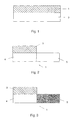
- Fig. 1 denotes a semiconductor substrate on which a first auxiliary layer 2 is applied.
- the first auxiliary layer 2 now becomes a first masking structure 3 formed, which a region 4 of the semiconductor substrate 1 covered and a further region 5 of the semiconductor substrate 1 leaves uncovered, as shown in Fig. 2 is.
- the unmasked area 5 can subsequently, for example by implantation, can be structured as shown in FIG. 3 is.
- the first masking structure 3 must be the rest In this case, the chip superstructures protrude so far that the following one Planarization step specifically removed these structures can be. 4 shows how the inversion of the masking structure 3 is being prepared.
- a second Auxiliary layer 6 on the first masking structure 3 and on the applied unmasked area 5 of the semiconductor substrate 1, whereupon all of the material towering above level 7 through planarization processes is removed.
- the exposed masking structure 3 can now, for example, by Etching, selectively removed, leaving only the second Auxiliary layer 6 remains, which is the inverted structure of the Masking 3 corresponds and as a masking structure for a subsequent structuring of area 4 of the semiconductor substrate 1 serves.
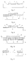
- 7 to 11 is the application of the invention Process shown on the manufacture of a bipolar transistor.
- the problem with bipolar transistors is that an intrinsic Base area and an emitter area centrally structured must become. Laterally this central area must be observed a defined distance, the base supply line structures (e.g. through an implant step or through the Growing a silicide). These two structuring steps must be exactly aligned with each other. Too big Distance means that the resistance of the base lead increases too small a distance or an overlap has the consequence that the base region is partially highly doped or that the Shorted emitter.
- 7 is the semiconductor substrate, in which the collector is already included, designated 8.
- the intrinsic base area should now be in area 9 and to the side of it, each observing one Distance a, extrinsic areas 10 for the base lead be formed.
- a first masking structure is used 11 applied, which is the intrinsic base area covers, as shown in Fig. 8.
- the Thickness exactly the distance a between intrinsic and extrinsic Base corresponds.
- spacer layer 12 spacers 13 are formed so that now how 9, the extrinsic areas, for example can be doped with boron.
- an auxiliary layer 14 on the first masking structure 11 Spacers and over the exposed substrate surface applied, so that now the structure shown in Fig. 10 is formed.
- the material that is outstanding over level 15 is through Planarization process removed, so that the masking structure 11 is exposed, whereupon it is removed by selective etching becomes.
Abstract
Description
Die Erfindung betrifft ein Verfahren zum Herstellen von Strukturen in Chips, bei welchem eine Folge von Strukturierungs-schritten selbstjustierend angewendet wird.The invention relates to a method for producing structures in chips, in which a sequence of structuring steps self-adjusting is applied.
In der Halbleiterfertigung sind üblicherweise mehrere aufeinanderfolgende Strukturierungsschritte notwendig, um Halbleiterbauelemente, wie beispielsweise bipolare Transistoren, zu verwirklichen. Jeder einzelne Strukturierungsschritt wird hierbei unter Verwendung einer Maske vorgenommen, wobei jedesmal eine Fotomaske genau ausgerichtet werden muß. Insbesondere muß ab dem zweiten Strukturierungsschritt die Fotomaske genau an der schon vorhandenen Struktur ausgerichtet werden, was bei den immer kleiner werdenden Strukturen in der Halbleiterfertigung hohe Anforderungen an die Justiergenauigkeit stellt. Gleichzeitig muß jedoch der Prozeßablauf möglichst einfach gehalten werden, um die Herstellungskosten möglichst niedrig zu halten.In semiconductor manufacturing, there are usually several consecutive ones Structuring steps necessary to make semiconductor components, such as bipolar transistors. Each individual structuring step is hereby using a mask, each time one Photo mask must be precisely aligned. In particular, from second structuring step the photo mask exactly on the already existing structure to be aligned with whatever the structures that are becoming smaller in semiconductor production place high demands to the adjustment accuracy. At the same time however, the process flow should be kept as simple as possible to keep the manufacturing costs as low as possible.
Die vorliegende Erfindung zielt darauf ab, ein einfaches Verfahren zum Herstellen von Strukturen in Chips zu schaffen, bei welchem ein Ausrichten der Fotomasken und die damit verbundenen Justierprobleme vermieden werden und welches für die Herstellung von kleinen Strukturen geeignet ist. Insbesondere sollen die Strukturierungsschritte selbstjustierend vorgenommen werden und ein einfacher Prozeßablauf gewährleistet sein.The present invention aims to be a simple method to create structures in chips at which aligning the photo masks and the associated Adjustment problems are avoided and which for the production of small structures. In particular, the Structuring steps are self-adjusting and a simple process flow can be guaranteed.
Zur Lösung dieser Aufgabe besteht das erfindungsgemäße Verfahren im wesentlichen darin, daß durch das Strukturieren einer ersten auf einem Träger aufgebrachten Hilfsschicht nach einer ersten Maskierung eine erste Maskierungsstruktur ausgebildet wird, welche wenigstens einen über die Oberfläche des Trägers vorragenden Teilbereich aufweist, daß nachfolgend ein weiterer Strukturierungsschritt, beispielsweise durch Ätzen, Implantieren oder CVD (chemical vapor deposition), unter Verwendung der zuvor hergestellten ersten Maskierungsstruktur als Maske vorgenommen wird und daß anschließend die erste Maskierungsstruktur zur Ausbildung einer zweiten Maskierungsstruktur dadurch invertiert wird, daß auf die erste Maskierungsstruktur wenigsten eine zweite Hilfsschicht aufgebracht, die so gebildete Struktur zumindest teilweise abgetragen und die dadurch freigelegte erste Hilfsschicht selektiv entfernt wird, worauf die zweite Maskierungsstruktur als Maske für einen weiteren Strukturierungsschritt verwendet wird. Dadurch, daß durch das Strukturieren einer ersten auf einen Träger aufgebrachten Hilfsschicht nach einer ersten Maskierung eine Maskierungsstruktur ausgebildet wird, welche wenigstens einen über die Oberfläche des Trägers vorragenden Teilbereich aufweist, wird die Voraussetzung dafür geschaffen, bei nachfolgenden Strukturierungsschritten eine Inversion der Struktur dahingehend vorzunehmen, daß der im ersten Schritt gebildete vorragende Teilbereich abgetragen wird und verbleibende Teile jeweils als Bezugselemente für die Selbstjustierung wirksam werden. Insbesonders wird die Voraussetzung dafür geschaffen, daß bei einem nachfolgend weiteren Strukturierungsschritt, beispielsweise durch Ätzen, Implantieren oder CVD (Chemical vapor deposition), die zuvor hergestellte erste Maskierungsstruktur als Maske eingesetzt werden kann, wobei anschließend an die erste Maskierungsstruktur eine weitere Maskierungsstruktur dadurch hergestellt werden kann, daß die erste Maskierungsstruktur invertiert wird. Die Inversion erfolgt hiebei erfindungsgemäß dadurch, daß auf die erste Maskierungsstruktur wengistens eine zweite Hilfsschicht aufgetragen wird und in der Folge ein zumindest teilweises Abtragen vorgenommen wird. Das Abtragen kann prinzipiell durch Planarisierung erfolgen, wobei eine derartige Planarisierung bisher nur zur Ausbildung von ebenen Oberflächenstrukturen, nicht aber, wie erfindungsgemäß vorgeschlagen, zum Invertieren einer Struktur verwendet wurde. Durch die Planarisierung, welche, wie es einer bevorzugten Weiterbildung entspricht, beispielsweise durch ein chemisch-mechanisches Schleifverfahren und/oder Rückätzverfahren vorgenommen werden kann, wird eine neue Struktur nach der teilweisen Materialabtragung der höher gelegenen Teile des Chip gebildet, bei welcher die erste Maskierungsstruktur, soweit sie noch verblieben ist, wiederum freigelegt wird und in der Folge selektiv entfernt wird. Die nun verbleibenden Teile der zweiten Hilfsschicht bilden eine zweite Maskierungsstruktur, welche als Maske für die weiteren Strukturierungsschritte verwendet wird. Insgesamt ergibt sich durch diese Abfolge von Strukturierungsschritten, bei welcher als wesentlicher Schritt eine Inversion der Struktur unter Verwendung von Planarisierungsverfahren vorgenommen wird, eine besonders einfache Verfahrensweise zur Ausbildung von kleinen Strukturen und insbesondere beispielsweise zur Ausbildung einer hohen Anzahl von Halbleiterschalt- oder Bauelementen, wie beispielsweise bipolaren Transistoren, auf der Oberfläche des Chips, sodaß eine höhere Bauteildichte bei gleichzeitig erhöhter Präzision der jeweiligen Schichtgrenzen erzielt werden kann.The method according to the invention exists to achieve this object essentially in that by structuring a first auxiliary layer applied to a support after a first Masking a first masking structure is formed, which protrude at least one over the surface of the carrier Sub-area has that subsequently another Structuring step, for example by etching, implanting or CVD (chemical vapor deposition), using the previously produced first masking structure made as a mask and that then the first masking structure for training a second masking structure thereby inverted is that at least a second on the first masking structure Auxiliary layer applied, at least the structure thus formed partially removed and the resulting first auxiliary layer is selectively removed, whereupon the second masking structure as a mask for a further structuring step is used. By structuring a first auxiliary layer applied to a support after a a masking structure is formed for the first masking, which protrude at least one over the surface of the carrier Sub-area is the prerequisite for this created one in subsequent structuring steps Inversion of the structure in such a way that the im first projecting sub-area formed is removed and remaining parts each as reference elements for the Self-adjustment take effect. In particular, the requirement created for the fact that in a subsequent Structuring step, for example by etching, implanting or CVD (Chemical vapor deposition), the previously made first masking structure can be used as a mask, a further one following the first masking structure Masking structure can be produced in that the first masking structure is inverted. The inversion takes place hiebei according to the invention in that the first masking structure when a second auxiliary layer is applied and subsequently carried out an at least partial removal becomes. The removal can in principle be carried out by planarization, such a planarization so far only for training of flat surface structures, but not, as according to the invention proposed to use for inverting a structure has been. Through the planarization, which, as one preferred further development corresponds, for example by a chemical-mechanical grinding process and / or etching back process can be made, a new structure after the partial Material removal of the higher parts of the chip formed, in which the first masking structure, insofar as it is still left, is again exposed and subsequently is selectively removed. The remaining parts of the second Auxiliary layer form a second masking structure, which as Mask is used for the further structuring steps. Overall, this sequence of structuring steps results in where as an essential step an inversion the structure using planarization techniques is a particularly simple procedure for training of small structures and especially for example to form a large number of semiconductor switching or Components, such as bipolar transistors, on the Surface of the chip, so that a higher component density at the same time increased precision of the respective layer boundaries can be achieved.
Wie bereits erwähnt erfolgt das Abtragen bevorzugt durch ein chemisch-mechanisches Schleifverfahren oder durch Rückätzverfahren. Im Falle der Verwendung von Rückätzverfahren für die Planarisierung zur Invertierung der Struktur wird mit Vorteil so vorgegangen, daß auf die erste Maskierungsstruktur zusätzlich zur zweiten Hilfsschicht eine Planarisierungsschicht aus einem Material aufgebracht wird, das gute Planarisierungseigenschaften besitzt. Die Planarisierungsschicht bildet in tiefer gelegenen Bereichen eine dickere Schicht als über den höhereren Chipteilen. Ätzt man nun gleichmäßig mit einer idealerweise gleichen Ätzrate für die Planarisierungsschicht und die höher gelegenen Strukturen, so überträgt sich die Topographie der planarisierten Schichtoberflächeauf die Chipoberfläche. Auf diese Weise wird sichergestellt, daß die gewünschte Inversion der Struktur mit hoher Präzision erreicht wird.As already mentioned, the removal is preferably carried out by a chemical-mechanical grinding or by etching back. In the case of using etchback methods for the Planarization to invert the structure is advantageous proceeded that in addition to the first masking structure to the second auxiliary layer a planarization layer from one Material is applied that has good planarization properties owns. The planarization layer forms in lower ones Areas a thicker layer than over the higher chip parts. Now you can etch evenly with an ideal one Etch rate for the planarization layer and the higher ones Structures, so the topography of the planarized is transferred Layer surface on the chip surface. That way ensures that the desired inversion of the structure with high precision is achieved.
Mit Vorteil wird erfindungsgemäß so vorgegangen, daß die zweite Hilfsschicht und gegebenenfalls die Planarisierungsschicht nicht planarisierend wird. Ein nicht planarisierendes Ätzen hat hiebei den Vorzug, daß die Materialabnahme gerichtet und in erster Linie vertikal erfolgt, wobei ein derartiges nicht planarisierendes Ätzen insbesondere für die Ausbildung von Abstandshaltern und damit für die Zwecke der Selbstjustierung von besonderem Vorteil ist. In bevorzugter Weise wird daher im Rahmen des Verfahrens so vorgegangen, daß auf die erste und/oder die zweite Maskierungsstruktur eine Schicht aufgebracht wird, welche anschließend zur Ausbildung eines Abstandhalters anisotrop geätzt wird. Durch Wahl der Stärke der auf die erste und/oder auf die zweite Maskierungsstruktur aufgebrachten Schicht wird in der Folge die Präzision der Justierung gewährleistet, da die verbleibenden Abstandhalter eine Stärke in Richtung der Oberfläche gemessen aufweisen, welche im wesentlichen der Stärke der aufgebrachten Schicht entspricht. Advantageously, the procedure according to the invention is such that the second Auxiliary layer and possibly not the planarization layer becomes planarizing. A non-planarizing etching has here the preference that the material take directed and in the first place Line is vertical, such a non-planarizing Etching especially for the formation of spacers and therefore especially for the purposes of self-adjustment Advantage is. It is therefore preferred in the context of the method proceeded so that the first and / or the second A masking structure is applied, which then anisotropic to form a spacer is etched. By choosing the strength of the first and / or is applied to the second masking structure in consequently ensures the precision of the adjustment, since the remaining spacers a thickness towards the surface have measured, which is essentially the strength of the applied layer corresponds.
Prinzipiell ist für die Auswahl der einzelnen Schichten in erster Linie das Kriterium maßgebend, daß jeweils abzutragende Schichten mit hoher Selektivität gegenüber nicht abzutragenden Schichten entfernt werden können. Es soll somit eine gute Selektivität für die jeweils sukzessive aufgetragenen Schichten und Hilfsschichten bzw. gegenüber dem Spacermaterial bestehen. Pinzipiell können hiebei alle üblichen und gebräuchlichen Schichten und Hilfsschichten, beispielsweise Polysilizium, Siliziumoxyd, Polymere, Silizide wie z.B. Titansilizid, Wolframsilizid oder dgl., Nitride und Metallschichten, wie beispielsweise Titan-, Aluminium- oder dgl. -schichten zum Einsatz gelangen.In principle for the selection of the individual layers in First and foremost the criterion that is to be deducted Layers with high selectivity compared to those that cannot be removed Layers can be removed. It is said to be good selectivity for the successively applied layers and Auxiliary layers or in relation to the spacer material. In principle can do all common and common layers and auxiliary layers, for example polysilicon, silicon oxide, Polymers, silicides such as e.g. Titanium silicide, tungsten silicide or Like., Nitride and metal layers, such as titanium, Aluminum or the like layers are used.
Mit Vorteil wird erfindungsgemäß so vorgegangen, daß die erste Maskierungsstruktur aus Siliziumnitrid besteht, sodaß in der Folge eine einfache Abtragung dieser Schicht mit konventionellen Methoden, beispielsweise mittels heißer Phosphorsäure gelingt. Mit Vorteil wird weiters die zweite Maskierungsstruktur aus Siliziumoxid ausgebildet und die Planarisierungsschicht aus einem organischen Polymer. Die Abtragung organischer Polymere kann durch thermische Verfahren und beispielsweise auch durch Plasmaätzen erfolgen, wobei Schichten aus Siliziumoxyd oder polykristallinem Silizium bei einem derartigen selektiven Abtrageschritt nicht verändert werden.Advantageously, the procedure according to the invention is such that the first Masking structure made of silicon nitride, so that in the Follow a simple removal of this layer with conventional ones Methods, for example using hot phosphoric acid. The second masking structure made of silicon oxide is also advantageous trained and the planarization layer from one organic polymer. The removal of organic polymers can by thermal processes and for example also by plasma etching take place, layers of silicon oxide or polycrystalline Silicon in such a selective removal step cannot be changed.
Mit Vorteil kann auch die zweite Hilfsschicht aus einem organischen Polymer bestehen, wobei in diesem Fall die selektive Entfernung dieser Planarisierungsschicht gegenüber den übrigen Schichten gleichfalls gewährleistet ist.The second auxiliary layer can advantageously also consist of an organic one Polymer exist, in which case the selective Removal of this planarization layer from the rest Layers is also guaranteed.
Wenn ein Trägermaterial zum Einsatz gelangt, welches keine Ätzselektivität gegenüber nachfolgend aufzubringenden Schichten aufweist, wird mit Vorteil so vorgegangen, daß der Träger selbst eine dritte Hilfsschicht ist, die aus einem Material mit guter Ätzselektivität zur ersten und zweiten Maskierungsstruktur besteht.If a carrier material is used that does not have any etching selectivity compared to layers to be applied subsequently has, is advantageously carried out so that the carrier itself a third auxiliary layer is made of a material with good Etching selectivity to the first and second masking structure consists.
Die Abscheidung der jeweiligen Schichten kann mit konventionellen Verfahren erfolgen. Mit Vorteil wird eine zweite Hilfsschicht mittels eines CVD-Verfahrens aufgebracht, wobei die zweite Hilfsschicht auch aus einem organischen Polymer bestehen kann, das mit einem Spin-Verfahren aufgebracht wird.The deposition of the respective layers can be done with conventional Procedure. A second auxiliary layer is advantageous applied by means of a CVD process, the second auxiliary layer also consist of an organic polymer can, which is applied with a spin process.
Das erfindungsgemäße Verfahren eignet sich bevorzugt für die Ausbildung von Bipolartransistoren, wobei aufgrund der hohen Präzision die elektrischen Parameter des Transistors exakter eingestellt werden können.The method according to the invention is preferably suitable for Formation of bipolar transistors, due to the high Precision the electrical parameters of the transistor more precise can be adjusted.
Die Erfindung wird nachfolgend anhand von in der Zeichnung schematisch erläuterten Ausführungsbeispieles näher erläutert. In dieser zeigen Fig. 1 bis 6 eine schematische Darstellung des erfindungsgemäßen Verfahrens und Fig. 7 bis 11 eine Anwendung des erfindungsgemäßen Verfahrens zur Herstellung von Bipolartransistoren.The invention is described below with reference to the drawing schematically explained embodiment. 1 to 6 show a schematic illustration of the inventive method and Fig. 7 to 11 an application of the inventive method for producing bipolar transistors.
In Fig. 1 ist mit 1 ein Halbleitersubstrat bezeichnet, auf welches
eine erste Hilfsschicht 2 aufgebracht ist. Durch geeignete
Maskierung der ersten Hilfsschicht 2 wird nun eine erste Maskierungsstruktur
3 ausgebildet, welche einen Bereich 4 des Halbleitersubstrats
1 bedeckt und einen weiteren Bereich 5 des Halbleitersubstrats
1 unbedeckt läßt, wie dies in Fig. 2 dargestellt
ist. Der unmaskierte Bereich 5 kann in der Folge, beispielsweise
durch Implantieren, strukturiert werden, wie dies in Fig. 3 dargestellt
ist. Die erste Maskierungsstruktur 3 muß die übrigen
Chipaufbauten hierbei soweit überragen, daß bei dem später folgenden
Planarisierungsschritt gezielt diese Strukturen abgetragen
werden können. Fig. 4 zeigt wie die Inversion der Maskierungsstruktur
3 vorbereitet wird. Zunächst wird eine zweite
Hilfsschicht 6 auf die erste Maskierungsstruktur 3 sowie auf den
unmaskierten Bereich 5 des Halbleitersubstrats 1 aufgebracht,
worauf das gesamte die Ebene 7 überragende Material durch Planarisierungsverfahren
abgetragen wird. Dadurch wird gleichzeitig
die Maskierungsstruktur 3 freigelegt und eine selektive Maskierung
des Bereiches 5 des Halbleitersubstrats 1 durch die zweite
Hilfsschicht 6 erreicht, wie dies in Fig. 5 dargestellt ist. Die
freigelegte Maskierungsstruktur 3 kann nun, beispielsweise durch
Ätzen, selektiv entfernt werden, sodaß lediglich die zweite
Hilfsschicht 6 verbleibt, welche der invertierten Struktur der
Maskierung 3 entspricht und als Maskierungsstruktur für eine
nachfolgende Strukturierung des Bereiches 4 des Halbleitersubstrates
1 dient. Fig. 6 zeigt, daß die zweite Maskierungsstruktur
6 exakt den bereits strukturierten Bereich des Halbleitersubstrats
bedeckt, sodaß nun selektiv der Bereich 4 bearbeitet werden
kann. Es ergibt sich somit, daß ausgehend von einer ersten
Maskierungsstruktur 3 durch eine Abfolge einfacher Verfahrensschritte
eine zweite Maskierungsstruktur 6 ausgebildet werden
kann, welche exakt an der ersten Maskierungsstruktur ausgerichtet
ist.In Fig. 1, 1 denotes a semiconductor substrate on which
a first
In den Fig. 7 bis 11 ist nun die Anwendung des erfindungsgemäßen
Verfahrens auf die Herstellung eines Bipolartransistors gezeigt.
Bei Bipolartransistoren stellt sich das Problem, daß ein intrinsischer
Basisbereich und ein Emitterbereich zentral strukturiert
werden muß. Seitlich dieses zentralen Bereiches muß, unter Einhaltung
eines definierten Abstandes, die Basiszuleitung strukturiert
werden (z.B. durch einen Implantschritt oder durch das
Aufwachsen eines Silizids). Diese beiden Strukturierungsschritte
müssen exakt aufeinander ausgerichtet werden. Ein zu großer
Abstand bedeutet, daß der Widerstand der Basiszuleitung zunimmt,
ein zu kleiner Abstand bzw. ein Überlappen hat zur Folge, daß
der Basisbereich teilweise hoch dotiert wird bzw. daß der
Emitter kurzgeschlossen wird. In Fig. 7 ist das Halbleitersubstrat,
in welchem bereits der Kollektor enthalten ist, mit 8 bezeichnet.
In einem Bereich 9 soll nun der intrinsische Basisbereich
und seitlich davon, jeweils unter Einhaltung eines
Abstandes a, extrinsische Bereiche 10 für die Basiszuleitung
ausgebildet werden. Hierfür wird zunächst eine erste Maskierungsstruktur
11 aufgebracht, welche den intrinsischen Basisbereich
abdeckt, wie dies in Fig. 8 dargestellt ist. Nachfolgend
wird eine Schicht 12 eines Spacermaterials aufgebracht, deren
Dicke genau dem Abstand a zwischen intrinsischer und extrinsischer
Basis entspricht. Durch anisotropes Ätzen der Spacerschicht
12 werden Abstandhalter 13 ausgebildet, sodaß nun, wie
in Fig. 9 dargestellt ist, die extrinsischen Bereiche, beispielsweise
mit Bor, dotiert werden können. Anschließend wird
eine Hilfsschicht 14 auf die erste Maskierungsstruktur 11, die
Abstandshalter sowie über die freiliegende Substratoberfläche
aufgebracht, sodaß nun die in Fig. 10 dargestellte Struktur entsteht.
Das über die Ebene 15 hervorragende Material wird durch
Planarisierungsverfahren abgetragen, sodaß die Maskierungsstruktur
11 freigelegt wird, worauf diese durch selektives Ätzen entfernt
wird. Die dadurch entstehende in Fig. 11 gezeigte Maskierungsstruktur
14 ermöglicht nun das selektive Dotieren des
Kollektorbereiches unter dem intrinsischen Basisbereich 9 mit
dem sogenannten SIC-Implantat (SIC = selektive implanted
collector). Darüber hinaus kann man mit Hilfe der Maskierungsstruktur
14 den Bereich über der intrinsischen Basis freilegen,
in den das Emitterpolysilizium abgeschieden wird. Das erfindungsgemäße
Prinzip der Strukturinversion kann für konventionelle
BJTs (BJT = bipolar junction transistor, bipolarer Sperrschicht
Transistor) mit implantierter Basis als auch für
Bipolartransistoren mit epitaktisch aufgewachsener Basis mit NPN
oder PNP-Polarität angewendet werden.7 to 11 is the application of the invention
Process shown on the manufacture of a bipolar transistor.
The problem with bipolar transistors is that an intrinsic
Base area and an emitter area centrally structured
must become. Laterally this central area must be observed
a defined distance, the base supply line structures
(e.g. through an implant step or through the
Growing a silicide). These two structuring steps
must be exactly aligned with each other. Too big
Distance means that the resistance of the base lead increases
too small a distance or an overlap has the consequence that
the base region is partially highly doped or that the
Shorted emitter. 7 is the semiconductor substrate,
in which the collector is already included, designated 8.
The intrinsic base area should now be in
Claims (13)
Applications Claiming Priority (2)
| Application Number | Priority Date | Filing Date | Title |
|---|---|---|---|
| AT0084199U AT4149U1 (en) | 1999-12-03 | 1999-12-03 | METHOD FOR PRODUCING STRUCTURES IN CHIPS |
| AT84199U | 1999-12-03 |
Publications (2)
| Publication Number | Publication Date |
|---|---|
| EP1111666A2 true EP1111666A2 (en) | 2001-06-27 |
| EP1111666A3 EP1111666A3 (en) | 2002-12-18 |
Family
ID=3501012
Family Applications (1)
| Application Number | Title | Priority Date | Filing Date |
|---|---|---|---|
| EP00890355A Withdrawn EP1111666A3 (en) | 1999-12-03 | 2000-11-29 | Process for making structures on integrated circuits |
Country Status (3)
| Country | Link |
|---|---|
| US (1) | US6562547B2 (en) |
| EP (1) | EP1111666A3 (en) |
| AT (1) | AT4149U1 (en) |
Families Citing this family (1)
| Publication number | Priority date | Publication date | Assignee | Title |
|---|---|---|---|---|
| US6780736B1 (en) * | 2003-06-20 | 2004-08-24 | International Business Machines Corporation | Method for image reversal of implant resist using a single photolithography exposure and structures formed thereby |
Citations (5)
| Publication number | Priority date | Publication date | Assignee | Title |
|---|---|---|---|---|
| US5447874A (en) * | 1994-07-29 | 1995-09-05 | Grivna; Gordon | Method for making a semiconductor device comprising a dual metal gate using a chemical mechanical polish |
| US5614430A (en) * | 1996-03-11 | 1997-03-25 | Taiwan Semiconductor Manufacturing Company Ltd. | Anti-punchthrough ion implantation for sub-half micron channel length MOSFET devices |
| US5614758A (en) * | 1991-07-26 | 1997-03-25 | Hewlett-Packard Company | Fully walled emitter-base in a bipolar transistor |
| EP0795899A1 (en) * | 1996-03-14 | 1997-09-17 | Daimler-Benz Aktiengesellschaft | Method for fabricating a heterojunction bipolar transistor |
| US5856225A (en) * | 1997-11-24 | 1999-01-05 | Chartered Semiconductor Manufacturing Ltd | Creation of a self-aligned, ion implanted channel region, after source and drain formation |
Family Cites Families (13)
| Publication number | Priority date | Publication date | Assignee | Title |
|---|---|---|---|---|
| US3837856A (en) * | 1967-04-04 | 1974-09-24 | Signetics Corp | Method for removing photoresist in manufacture of semiconductor devices |
| US4758528A (en) * | 1980-07-08 | 1988-07-19 | International Business Machines Corporation | Self-aligned metal process for integrated circuit metallization |
| DE3124572A1 (en) | 1981-06-23 | 1982-12-30 | Siemens AG, 1000 Berlin und 8000 München | METHOD FOR PRODUCING SCHOTTKY DIODES |
| DE3304588A1 (en) | 1983-02-10 | 1984-08-16 | Siemens AG, 1000 Berlin und 8000 München | METHOD FOR PRODUCING MOS TRANSISTORS WITH FLAT SOURCE / DRAIN AREAS, SHORT CHANNEL LENGTHS AND A SELF-ADJUSTED CONTACT LEVEL CONSTRUCTING FROM A METAL SILICIDE |
| DE3330895A1 (en) | 1983-08-26 | 1985-03-14 | Siemens AG, 1000 Berlin und 8000 München | METHOD FOR PRODUCING BIPOLAR TRANSISTOR STRUCTURES WITH SELF-ADJUSTED EMITTER AND BASE AREAS FOR HIGH-FREQUENCY CIRCUITS |
| GB2172744B (en) * | 1985-03-23 | 1989-07-19 | Stc Plc | Semiconductor devices |
| US4755476A (en) | 1985-12-17 | 1988-07-05 | Siemens Aktiengesellschaft | Process for the production of self-adjusted bipolar transistor structures having a reduced extrinsic base resistance |
| US4871684A (en) * | 1987-10-29 | 1989-10-03 | International Business Machines Corporation | Self-aligned polysilicon emitter and contact structure for high performance bipolar transistors |
| US5266505A (en) * | 1992-12-22 | 1993-11-30 | International Business Machines Corporation | Image reversal process for self-aligned implants in planar epitaxial-base bipolar transistors |
| JPH07142504A (en) | 1993-11-19 | 1995-06-02 | Oki Electric Ind Co Ltd | Bipolar semiconductor integrated circuit and manufacturing method |
| JPH07221321A (en) | 1994-02-08 | 1995-08-18 | Nippondenso Co Ltd | Semiconductor device and its manufacture |
| JPH1012871A (en) | 1996-06-21 | 1998-01-16 | Toshiba Corp | Manufacture of semiconductor device |
| US5798568A (en) * | 1996-08-26 | 1998-08-25 | Motorola, Inc. | Semiconductor component with multi-level interconnect system and method of manufacture |
-
1999
- 1999-12-03 AT AT0084199U patent/AT4149U1/en not_active IP Right Cessation
-
2000
- 2000-11-29 EP EP00890355A patent/EP1111666A3/en not_active Withdrawn
- 2000-12-01 US US09/727,389 patent/US6562547B2/en not_active Expired - Lifetime
Patent Citations (5)
| Publication number | Priority date | Publication date | Assignee | Title |
|---|---|---|---|---|
| US5614758A (en) * | 1991-07-26 | 1997-03-25 | Hewlett-Packard Company | Fully walled emitter-base in a bipolar transistor |
| US5447874A (en) * | 1994-07-29 | 1995-09-05 | Grivna; Gordon | Method for making a semiconductor device comprising a dual metal gate using a chemical mechanical polish |
| US5614430A (en) * | 1996-03-11 | 1997-03-25 | Taiwan Semiconductor Manufacturing Company Ltd. | Anti-punchthrough ion implantation for sub-half micron channel length MOSFET devices |
| EP0795899A1 (en) * | 1996-03-14 | 1997-09-17 | Daimler-Benz Aktiengesellschaft | Method for fabricating a heterojunction bipolar transistor |
| US5856225A (en) * | 1997-11-24 | 1999-01-05 | Chartered Semiconductor Manufacturing Ltd | Creation of a self-aligned, ion implanted channel region, after source and drain formation |
Non-Patent Citations (2)
| Title |
|---|
| BURGHARTZ J N ET AL: "APCVD-grown self-aligned SiGe-base HBTs" PROCEEDINGS OF THE BIPOLAR/BICOMS CIRCUITS AND TECHNOLOGY MEETING, 1993, MINNEAPOLIS, MN, USA 4-5 OCT. 1993, NEW YORK, NY, USA, IEEE, 4. Oktober 1993 (1993-10-04), Seiten 55-62, XP010244210 ISBN: 0-7803-1316-X * |
| SHIGEMATSU H ET AL: "Ultrahigh fT AND fmax New Self-Alignment InP/InGaAs HBT's with a Highly Be-doped Base Layer Grown by ALE/MOCVD" IEEE ELECTRON DEVICE LETTERS, IEEE INC. NEW YORK, US, Bd. 16, Nr. 2, 1. Februar 1995 (1995-02-01), Seiten 55-57, XP000486726 ISSN: 0741-3106 * |
Also Published As
| Publication number | Publication date |
|---|---|
| EP1111666A3 (en) | 2002-12-18 |
| US6562547B2 (en) | 2003-05-13 |
| AT4149U1 (en) | 2001-02-26 |
| US20030044723A1 (en) | 2003-03-06 |
Similar Documents
| Publication | Publication Date | Title |
|---|---|---|
| EP0013317B1 (en) | Process for the manufacture of field-effect transistors | |
| DE10214066B4 (en) | Semiconductor device having a retrograde doping profile in a channel region and method of making the same | |
| DE19820223C1 (en) | Variable doping epitaxial layer manufacturing method | |
| DE19527131B4 (en) | Semiconductor device with a T-shaped gate structure and method for its production | |
| EP0021147B1 (en) | Process for producing broad and deeply penetrating isolation trenches in a semiconductor substrate | |
| EP0020998B1 (en) | Process for making a bipolar transistor with an ion-implanted emitter | |
| DE2729171C2 (en) | Process for manufacturing an integrated circuit | |
| DE2926874A1 (en) | METHOD FOR PRODUCING LOW-RESISTANT, DIFFUSED AREAS IN SILICON GATE TECHNOLOGY | |
| DE10351008B4 (en) | A method of fabricating transistors having elevated drain and source regions of different height and a semiconductor device | |
| DE2744059A1 (en) | METHOD FOR THE COMMON INTEGRATED PRODUCTION OF FIELD EFFECT AND BIPOLAR TRANSISTORS | |
| EP0005185A1 (en) | Method for simultaneously forming Schottky-barrier diodes and ohmic contacts on doped semiconductor regions | |
| DE3540422C2 (en) | Method for producing integrated structures with non-volatile memory cells which have self-aligned silicon layers and associated transistors | |
| DE102015204411B4 (en) | Transistor and method of making a transistor | |
| DE10107012A1 (en) | Simultaneous formation of poly-poly capacitor, MOS transistor and bipolar transistor on substrate used in production of integrated circuits comprises using polycrystalline silicon to form electrodes | |
| DE60034265T2 (en) | Semiconductor device with SOI structure and its manufacturing method | |
| DE2849373A1 (en) | METHOD OF MANUFACTURING A SEMICONDUCTOR DEVICE | |
| EP0000545B1 (en) | Method for forming a semiconducter device with self-alignment | |
| DE2429957A1 (en) | PROCESS FOR PRODUCING A DOPED ZONE OF A CONDUCTIVITY TYPE IN A SEMICONDUCTOR BODY | |
| EP1701386A1 (en) | Method for intergration of two bilopar transistors on an semiconductor substrate, semiconductor structure in an semiconductor body and an cascod circuit | |
| DE3128629A1 (en) | RESET PROCESS FOR INTEGRATED CIRCUITS | |
| EP1111666A2 (en) | Process for making structures on integrated circuits | |
| DE2930780C2 (en) | Method of manufacturing a VMOS transistor | |
| EP1436842A1 (en) | Bipolar transistor and method for producing the same | |
| DE10241397A1 (en) | Semiconductor element with a T-shaped gate structure with sidewall spacers which are produced in-situ, and a method for producing the semiconductor element | |
| DE19857852B4 (en) | Semiconductor device and method for its production |
Legal Events
| Date | Code | Title | Description |
|---|---|---|---|
| PUAI | Public reference made under article 153(3) epc to a published international application that has entered the european phase |
Free format text: ORIGINAL CODE: 0009012 |
|
| AK | Designated contracting states |
Kind code of ref document: A2 Designated state(s): AT BE CH CY DE DK ES FI FR GB GR IE IT LI LU MC NL PT SE TR |
|
| AX | Request for extension of the european patent |
Free format text: AL;LT;LV;MK;RO;SI |
|
| PUAL | Search report despatched |
Free format text: ORIGINAL CODE: 0009013 |
|
| AK | Designated contracting states |
Kind code of ref document: A3 Designated state(s): AT BE CH CY DE DK ES FI FR GB GR IE IT LI LU MC NL PT SE TR |
|
| AX | Request for extension of the european patent |
Free format text: AL;LT;LV;MK;RO;SI |
|
| 17P | Request for examination filed |
Effective date: 20030227 |
|
| 17Q | First examination report despatched |
Effective date: 20030401 |
|
| AKX | Designation fees paid |
Designated state(s): DE FR GB |
|
| STAA | Information on the status of an ep patent application or granted ep patent |
Free format text: STATUS: THE APPLICATION IS DEEMED TO BE WITHDRAWN |
|
| 18D | Application deemed to be withdrawn |
Effective date: 20030812 |