EP1113828B1 - Respiratory suction catheter apparatus - Google Patents
Respiratory suction catheter apparatus Download PDFInfo
- Publication number
- EP1113828B1 EP1113828B1 EP99946768.1A EP99946768A EP1113828B1 EP 1113828 B1 EP1113828 B1 EP 1113828B1 EP 99946768 A EP99946768 A EP 99946768A EP 1113828 B1 EP1113828 B1 EP 1113828B1
- Authority
- EP
- European Patent Office
- Prior art keywords
- catheter
- flap
- manifold
- endotracheal
- port
- Prior art date
- Legal status (The legal status is an assumption and is not a legal conclusion. Google has not performed a legal analysis and makes no representation as to the accuracy of the status listed.)
- Expired - Lifetime
Links
Images


Classifications
-
- A—HUMAN NECESSITIES
- A61—MEDICAL OR VETERINARY SCIENCE; HYGIENE
- A61M—DEVICES FOR INTRODUCING MEDIA INTO, OR ONTO, THE BODY; DEVICES FOR TRANSDUCING BODY MEDIA OR FOR TAKING MEDIA FROM THE BODY; DEVICES FOR PRODUCING OR ENDING SLEEP OR STUPOR
- A61M16/00—Devices for influencing the respiratory system of patients by gas treatment, e.g. mouth-to-mouth respiration; Tracheal tubes
- A61M16/04—Tracheal tubes
- A61M16/0463—Tracheal tubes combined with suction tubes, catheters or the like; Outside connections
-
- Y—GENERAL TAGGING OF NEW TECHNOLOGICAL DEVELOPMENTS; GENERAL TAGGING OF CROSS-SECTIONAL TECHNOLOGIES SPANNING OVER SEVERAL SECTIONS OF THE IPC; TECHNICAL SUBJECTS COVERED BY FORMER USPC CROSS-REFERENCE ART COLLECTIONS [XRACs] AND DIGESTS
- Y10—TECHNICAL SUBJECTS COVERED BY FORMER USPC
- Y10S—TECHNICAL SUBJECTS COVERED BY FORMER USPC CROSS-REFERENCE ART COLLECTIONS [XRACs] AND DIGESTS
- Y10S128/00—Surgery
- Y10S128/91—Anesthesia gas scavenging system
-
- Y—GENERAL TAGGING OF NEW TECHNOLOGICAL DEVELOPMENTS; GENERAL TAGGING OF CROSS-SECTIONAL TECHNOLOGIES SPANNING OVER SEVERAL SECTIONS OF THE IPC; TECHNICAL SUBJECTS COVERED BY FORMER USPC CROSS-REFERENCE ART COLLECTIONS [XRACs] AND DIGESTS
- Y10—TECHNICAL SUBJECTS COVERED BY FORMER USPC
- Y10S—TECHNICAL SUBJECTS COVERED BY FORMER USPC CROSS-REFERENCE ART COLLECTIONS [XRACs] AND DIGESTS
- Y10S128/00—Surgery
- Y10S128/912—Connections and closures for tubes delivering fluids to or from the body
Definitions
- the present invention relates to a respiratory suction catheter system with an improved mechanism for cleaning the tip of the catheter without drawing an excessive amount of air from the respiration circuit to which the endotracheal catheter is attached.
- the present invention relates principally to a closed suction endotracheal catheter system which provides improved cleaning of the catheter while minimizing or eliminating air drawn from the patient's ventilation circuit.
- an artificial airway such as an endotracheal tube
- the artificial airway's function is primarily to keep the patient's airway open so that adequate lung ventilation can be maintained during the procedure.
- the endotracheal tube will be left in the patient for a prolonged period of time. For example, with many patients, the endotracheal tube will remain in place to sustain mechanical ventilation for the life of the patient.
- an endotracheal tube is to be left in place for any substantial amount of time, it is critical that respiratory secretions be periodically removed. This is most often accomplished with the use of a respiratory suction catheter which is advanced into the endotracheal tube. As the suction catheter is withdrawn, a negative pressure is applied to the interior of the catheter to draw mucus and other secretions from the patient's respiratory system. While a substantial amount of the mucus and other secretions will be withdrawn through the catheter lumen, a portion of the mucus and other secretions remain on the outside of the catheter.
- patient secretions can contain infectious agents, such as streptococcus, pseudomonus, staphylococcus and even HIV, it is important to shield clinicians from contact with the catheter. Likewise, it is important to shield patients from communicable pathogens in the environment and those which may be carried by the clinician. This is particularly important because patients on mechanical ventilation often have compromised immune systems.
- suctioning a patients' artificial airway potentially interferes with proper respiration.
- the most common group of patients who have indwelling endotracheal tubes for prolonged periods are those who must be mechanically ventilated.
- Mechanically ventilated patients will typically have a fitting or manifold attached to the proximal end of the endotracheal tube (i.e., the end extending outside the patient) at an endotracheal tube hub.
- a pair of ventilator tubes extend from a mechanical ventilator and are typically attached to the manifold by an adapter. One tube provides inspiratory air to the patient for inhalation. The other tube allows for exhaled or expiratory air to exit the system.
- Palmer improved the system by reducing the risk of cross-contamination between the patient and the medical personnel using the device. Since that time, there has been a significant shift toward the use of closed suction catheter systems.
- closed suction catheters The advantage of closed suction catheters is that the ventilating circuit is not detached from the patient during suction procedures, as it is during open suction procedures. Because the catheter is reused a number of times over a twenty-four hour period, it is important that mucus and other secretions be cleaned from the catheter prior to periods of non-use. If the secretions are not removed, the risk of auto-contamination increases. It is also important to clean the lumen of the catheter to maintain suction efficiency.
- suction also causes a volume of respiratory air to be removed through the catheter.
- the air that is evacuated potentially disrupts the carefully controlled ventilatory cycles.
- the amount of respiratory air available to the patient is potentially decreased as a result of catheter cleaning. If the clinician has a hard time cleaning secretions from the catheter, suction may be applied through the catheter several times, thereby repeatedly drawing air from the ventilatory circuit.
- closed suction catheters have been developed to have a cleaning or lavage chamber which is physically isolated from the ventilation circuit.
- a closed suction catheter which has a lavage chamber configured to receive the distal tip of the catheter as it is withdrawn from the manifold.
- a wall is then slid from an open position to a closed position to isolate the distal end of the catheter from the manifold and the ventilation circuit.
- a port is commonly provided to inject lavage solution into the cleaning chamber.
- the cleaning liquid commonly remains in the catheter due to the lack of airflow.
- contaminated liquids remaining in the catheter lumen can be reintroduced to the patient when the cleaning chamber is opened.
- the closed suction catheters presently available suffer from the inability to clean the catheter tip to the most desirable extent. If pathogens or other contaminants remain on the catheter for too long, they can auto-contaminate the patient. Additionally, if mucus and other secretions dry on the catheter, they can interfere with the suction efficiency, present an unsightly appearance and necessitate premature replacement of the closed suction catheter apparatus. Thus, there is a need for a catheter apparatus which has a mechanism for more effectively cleaning the distal end of the catheter without creating a substantial draw on respiratory air in the ventilation circuit
- the present invention may provide such a respiratory suction catheter apparatus which improves removal of mucus and other secretions from the distal tip of the catheter.
- the present invention may provide such a respiratory suction catheter apparatus which causes cleaning to be affected in a turbulent fluid flow.
- the present invention may provide such a respiratory suction catheter apparatus which is easy to use and relatively inexpensive
- an improved respiratory suction catheter apparatus typically include a manifold for attachment to an artificial airway, such as an endotracheal tube, to form a ventilation circuit, a catheter which is displaceable through the manifold and into the artificial airway to suction secretions from the artificial airway and lungs, and a valve mechanism disposed adjacent the ventilation circuit to minimize the air drawn from the ventilation circuit of a patient while the catheter is being cleaned
- valve mechanism may be configured to automatically engage the catheter tip after it is withdrawn through the manifold to thereby minimize the amount of air drawn into the catheter during cleaning.
- valve mechanism may be configured to lock a closed position when it is pulled toward the withdrawn catheter to thereby maintain isolation between the catheter tip and the airway through the manifold.
- valve mechanism may be provided with an air makeup to allow makeup air into the catheter and thereby ensure proper evacuation of secretions and any liquid used to clean the catheter.
- an air turbulence enhancing mechanism may be provided for increasing turbulent airflow around the distal end of the catheter to thereby improve removal of secretions from the catheter.
- an air makeup mechanism may be disposed so as to provide makeup air to the distal end of the catheter which is not drawn from the ventilation circuit.
- a pair of wiper seals are used to more effectively clean the distal end of the catheter tube.
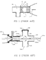
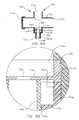
- FIG. 1 there is shown a cross-sectional view of a manifold 10 and catheter cleansing mechanism 14 in accordance with the teachings of the prior art.
- the manifold has a valve mechanism in the form of a rotatable rod 18 for selectively isolating a lavage chamber 20 from the ventilation circuit 26.
- a lavage solution can be injected through a side port 30 to help wash the mucus and other secretions from the exterior of the catheter 22.
- the lavage chamber is not configured for makeup air to enter when the rotatable rod 18 is closed, a vacuum can be created in the lavage chamber 20 which interferes with effective suctioning.
- FIG. 1 An additional disadvantage of the embodiment shown in FIG. 1 is that the closure mechanism for such devices typically must be manually activated. If the user fails to close the rotatable rod 18, actuation of suction through the catheter will draw air from the ventilation circuit 26.
- FIG. 2 there is shown a cross-sectional view of an alternative embodiment of the prior art.
- the manifold 100 is provided with a plurality of ports 104.
- a first port 104a is attached to the hub of an endotracheal tube of the patient to conduct respiratory air to and from the endotracheal tube.
- the manifold forms part of a ventilation circuit.
- the air is typically provided to and removed from the manifold through a second port 104b which is attached to a pair of ventilation tubes via a connector (not shown).
- the ventilation tubes are, in turn, connected to a mechanical ventilator (not shown) in a manner which will be well known to those skilled in the art.
- a third port 104c is provided opposite the second port 104b.
- the third port 104c is typically covered with a cap 108 which is removed when "blow-by" is desired to wean a patient from forced ventilation.
- the manifold also has a fourth port 104d.
- a coupling 112 is configured to form a force-fit engagement with the fourth port 104d and effectively connects the catheter 116 and a protective sleeve 120 to the manifold 100.
- Disposed adjacent a proximal end of the coupling 112 is a lavage port 124 through which a cleaning liquid can be injected to rinse the exterior of the catheter 116.
- Such a configuration is advantageous because the lavage port 124 is positioned adjacent a seal 128 which is configured to wipe mucus and other secretions from the catheter 116 as is drawn through the seal.
- a user will typically withdraw the catheter 116 until the distal end 116a thereof is positioned slightly distally of the seal 128, and then the cleaning solution will be injected into the lavage port 124 to assist in the removal of secretions. While such a method of removing the secretions is generally effective, it can draw more air from the ventilation circuit 132 than is necessary to effectively clean the distal end 116a of the catheter 116. Additionally, it is common for respiratory therapists and other clinicians to maintain the suction on as the distal end 116a of the catheter 116 is drawn from the first port 104a to a position immediately adjacent the seal 128.
- FIG. 3A there is shown a cross-sectional view of a portion of an improved endotracheal catheter, generally indicated at 200.
- the endotracheal catheter includes a manifold, generally indicated at 204 and a catheter 208.
- the manifold 204 includes a plurality of ports 212a-c.
- a first port 212a is configured for attachment to the proximal end of an artificial airway, such as the hub of an endotracheal tube, tracheostomy tube, etc.
- a second port 212b is typically connected to a pair of ventilator tubes (not shown) by means of an adaptor (not shown), in accordance with common practice in the art.
- distal refers generally to the direction of the patient
- proximal refers to the direction of the user.
- the drawings of FIG. 2A are oriented such that the distal (patient) end is toward the top of the page, while the proximal (user) end is toward the bottom of the page.
- conditioned inspiratory air is forced through one of the ventilator tubes, through the second port 212b and the first port 212a and into the patient's lungs via the artificial airway. Exhaled air is carried through the first port 212a and then the second port 212b and out through the other ventilator tube.
- the manifold 204 forms part of a ventilation circuit 214 through which respiratory air is cycled.
- a third port 212c is also forming part of the manifold 204.
- the third port 212c is typically covered by a cap 216.
- the cap 216 may be removed from the third port 212c so that oxygenated air is passed by the patient's endotracheal tube, but inspiratory air is not forced into the patient's lungs by means of a totally closed circuit. This situation, commonly called “blow-by,” enables the patient to gradually resume natural or spontaneous breathing.
- the manifold 204 also has a fourth port 212d.
- the fourth port 212d is disposed generally opposite the first port 212a and is configured to allow the catheter 208 to slide therethrough and into the first port to enable suctioning of the patient. At the completion of suctioning, the catheter 208 is pulled back into the fourth port 212d to prevent interference with the ventilation circuit 214.
- a coupling or adapter 220 Disposed between the wall forming the fourth port 212d and the catheter 208 is a coupling or adapter 220.
- the adapter 220 engages the wall defining the fourth port 212d.
- the adapter 220 engages a collar 224 which closely surrounds the catheter 208 so as to leave a small cylindrical space 226 around the catheter 208.
- the space between the catheter 208 and the collar 224 is between 0.005 and 0.015 inches (between 0.127 and 0.381 mm). This proximity provides two important advantages.
- Injecting lavage/cleaning solution through the lavage port 228 further removes the secretions from the exterior of the catheter 208 and enhances evacuation by suction in the catheter. This configuration also minimizes the volume of air and cleaning solution necessary to effect cleaning.
- While the collar 224 configuration shown in FIG. 3A is beneficial, it is still common to have secretions build up on the distal end 208a of the catheter 208. If such build up is not promptly removed, it can interfere with the ability of the catheter to properly suction the patient. It can also serve as a culture medium for pathogens within the closed suction catheter system.
- a flap 232 is hingedly attached to an annular ring 236 disposed inside the fourth port 212d so as to enable the flap 232 to pivot with respect to the ring to form a self-closing valve member.
- the flap 232 could be attached directly to the wall of the manifold 204 defining the fourth port 212d or to the adapter 220.
- the hinged attachment 240 allows the flap 232 to selectively move while maintaining alignment with the catheter tip, thereby creating a self-closing flap valve.
- the flap 232 is positioned to align with the distal end 208a of the catheter 208 when the catheter is almost completely withdrawn into the collar 224.
- the hinged attachment 240 is sufficiently flexibly that suction through the distal end 208a of the catheter 208 will draw the flap 232 proximally from a first, distal position into a second, proximal position, wherein the flap contacts with the distal end of the catheter.
- the flap 232 and related structures form a self-closing valve wherein no additional external manipulation of the catheter system is needed to close the valve.
- the catheter 208 includes a primary aperture 244 in the distal end 208a and one or more lateral apertures 248 positioned slightly proximal from the distal end.
- suction through catheter tip aperture 244 is dramatically reduced or eliminated.
- Decrease in suction flow through the aperture 244 causes increased suction flow in the lateral apertures 248, thereby increasing the ability of the lateral apertures to evacuate any secretions contained between the outside of the catheter 208 and the interior of the collar 224.
- the lateral apertures 248 are generally smaller than the distal aperture 244 and because airflow to the lateral apertures is limited by the collar 224, a substantial decrease in the amount of air drawn from the ventilation circuit is achieved while simultaneously improving cleaning of the catheter 208.
- the proximal side 232a (i.e., the side opposite the ventilation circuit 214) of the flap 232 is generally planar. In such a configuration, the proximal side 232a of the flap 232 will typically form a substantially complete seal with the distal end 208a of the catheter 208.
- FIG. 3C there is shown a close-up cross-sectional view of the example shown in FIGs. 3A and 3B with a slight modification to the flap 232.
- the flap 232' in FIG. 3C has a channel 252 formed therein on the proximal side 232a'.
- the channel 252 prevents the flap 232' from forming an airtight engagement with the distal end 208a of the catheter 208.
- the channel 252 ensures that a measured volume of air will be drawn into the aperture 244 at the distal most end 208 of the catheter.
- the measured volume of air which is drawn in through the channel 252 can have an important effect. Specifically, the air creates turbulent airflow both within the catheter 208 and immediately around its exterior. The turbulent airflow in turn, assists in breaking up agglomerations of mucus and secretions which lavage/cleaning solution alone may not. Thus, the turbulent airflow helps to provide improved cleaning of the distal end 208a of the catheter 208. This is in sharp contrast to many of the prior art devices which have advocated the use of a lavage/cleaning chamber to clean the exterior of the catheter. Because the lavage/cleaning chamber is usually substantially larger than the catheter or because makeup air is not specifically provided, it is difficult to create turbulent airflow within the chamber. Without turbulent airflow, the mucus and other secretions are often not removed from the exterior of the catheter.
- FIG. 3D there is shown yet another variation of the flap 232 shown in FIGs. 3A and 3B .
- the flap 232" Rather than having a channel formed in a proximal side thereof, the flap 232" has an aperture 260 formed therein so as to allow a relatively small amount of air to pass through the flap 232".
- the small hole creates turbulent airflow at the distal end 208a of the catheter 208 and thereby improves cleaning. It is currently believed that an aperture 260 in the flap 232" with a diameter of about 0.03 inches (0.762 mm) is preferred.
- FIG. 3E shows an example similar to those shown in FIGs. 3A through 3D , except that the flap 232 is disposed to engage the distal end 224a of the collar 224 rather than the distal end 208a of the catheter 208. In such a configuration, suction flow can still be achieved through the aperture 244 at the distal end 208a of the catheter 208.
- a source ofmakeup air will be provided. This can be accomplished by using either of the flap configurations shown in FIGs. 3C and 3D .
- a small hole can be formed in the collar 224 to facilitate a small amount of makeup air being present to enhance suction flow and to increase turbulence.
- the result is an improved ability to clean the distal end 208a of the catheter 208, while at the same time significantly reducing the amount of air which is withdrawn from the ventilation circuit 214.
- consistent ventilation is provided to the patient, and the clinician is able to more easily clean the catheter 208.
- the improved respiratory suction catheter apparatus 300 includes a manifold 304 and a catheter 308.
- the manifold 304 includes a first port 312a, a second port 312b, a third port 312c and a fourth port 312d.
- An adapter 320 is disposed in the fourth port 312d in such a manner as to make the manifold 304 and the catheter 308 a functionally integrated unit.
- the adapter 320 may be adhesively attached to the manifold 304, or may be simply force-fit.
- annular ring is not disposed in the manifold 304 independent of the adapter 320. Rather, an annular ring 326 extends inwardly from a distal end 320a of the adapter 320.
- the annular ring 326 defines an aperture or opening 330 through which the catheter 308 can be extended.
- the opening 330 is slightly larger than the exterior of the catheter 308.
- a flap 336 is also extending inwardly from the adapter 320.
- the flap 336 is preferably hingedly attached to either the adapter directly or to the annular ring 326. When no suction is applied to the catheter 308, or when the distal end 308a of the catheter is disposed distally from the flap 336, the flap will generally extend distally from the annular ring 326 and provide virtually no resistance to advancement of the catheter 308.
- the embodiment in FIGs. 4A through 4C has a makeup air inlet, generally indicated at 350 which is formed in a portion of the wall defining the fourth port 312d of the manifold and the adapter 320.
- the makeup air inlet 350 preferably includes a filter 354 which is selected to substantially prevent cross-contamination between the environment/clinicians and the patient. Disposed adjacent to the filter material is a flexible barrier 358 which forms a one-way valve 360.
- the one-way valve 358 will generally be closed when the catheter 308 is in an extended position, wherein the catheter extends through the opening 330 in the annular ring 326.
- a vacuum will quickly develop on the side of the flap 336 opposite the ventilation circuit 340.
- the vacuum causes the one-way valve 358 to open and allow a supply of makeup air to enter the chamber.
- the makeup air flowing past the flexible one-way valve member 358 helps to create turbulent airflow and facilitate removal of any respiratory secretions on the catheter 308.
- the one-way valve 358 could be configured to provide very little resistance to air inflow, or could be configured to require a substantial vacuum to be present before makeup air is allowed into the area proximal the flap 336.
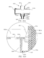
- FIG. 5A there is shown a fragmented, cross-sectional view of an alternative example of an improved respiratory suction catheter apparatus, generally indicated at 400.
- the respiratory suction catheter apparatus includes a manifold 404 and a catheter 408 which is moveable through the manifold to suction secretions from a patient's lungs.
- the manifold includes a first port 412a for attachment to an endotracheal tube or other artificial airway, a second port 412b for attachment to the ventilator tubes of a mechanical ventilator, a third port 412c which is covered with a cap 416, and a fourth port 412d which receives the connector or adaptor 420.
- valve 424 Disposed at the distal end 420a of the adaptor 420 is a valve 424 in a configuration which is commonly referred to as a duckbill valve.
- the valve 424 is formed by a piece of resilient material which opens as the catheter 408 is advanced therethrough, and closes when the catheter is withdrawn.
- the valve 424 is attached to the adaptor 420 by a flexible base 428.
- an air inlet 432 which includes a filter material 436 and a resilient member 440 configured to form a one-way valve 444 similar to that discussed in the previous example.
- a filter material 436 and a resilient member 440 configured to form a one-way valve 444 similar to that discussed in the previous example.
- the valve 424 shown in FIGs 5A through 5C is substantially advanced in several respects.
- the interior of the valve 424 has helical grooves 450 formed therein.
- the helical grooves 450 help to create turbulent airflow around the distal end 408a of the catheter 408.
- the flexible base 428 is configured to allow the valve 420 to be drawn toward the collar 460 to thereby reduce space and improve removal of secretions from the exterior of the catheter 408.
- FIG. 5B there is shown a cross-sectional view similar to that shown in FIG. 5A , but with the distal end 408a of the catheter 408 in a retracted position.
- the suction through the catheter works against the flexible base 428 of the valve and draws the valve toward the collar 460.
- a pair of air inlets 470 are disposed at the base 428 of the valve 424 and allow air into the valve.
- valve 424 may return to the position shown in FIG. 5A , except that it will be closed as the catheter 408 remains substantially in the collar until the next use.
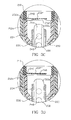
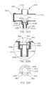
- FIG. 6A there is shown a cross-sectional view of yet another alternative example of an improved endotracheal catheter made in accordance with the principles of the present invention.
- the endotracheal catheter 00 includes a manifold 504 and a catheter 508.
- the manifold 504 has a first port 512a for attachment to the hub of an artificial airway of a patient, and a second port 512b for attachment to the ventilator tubes (not shown) of a mechanical ventilator so as to define a ventilation circuit 516.
- the manifold also includes a third port 512c which is configured to receive the catheter 508. Disposed in the third port 512c are a pair of floating flexible disks or membranes 520 and 524. Each of the disks defines an aperture or opening 528 and 532, respectively, through which the catheter 508 may be slid. An end view of the disks 520 and 524 with the catheter being slid therethrough is shown in FIG. 6D .
- a second lavage port 550 can be added distally from the disks.
- the second lavage port 550 typically would not be used for cleaning of the catheter 508.
- FIG. 7A there is shown a cross-sectional view of still another example of an improved endotracheal catheter. Most portions of the endotracheal catheter shown in FIG. 7A are the same as those discussed with respect to FIGs. 6A through 6D and are numbered accordingly.
- the one major difference between the examples of FIGs. 6A through 6D and FIG. 7A is that the disks 520 and 524 of the previous embodiment are replaced with a resilient closing membrane 570 which is attached at one end 570a to the manifold 504 and at an opposing end 570b to an adapter 572 holding the catheter 508.
- the adapter 572 or manifold 504 can be rotated to twist the membrane 570 and thereby either reduce or enlarge the size of a hole 580 ( FIG. 7B ) formed by the material.
- a hole 580 FIG. 7B
- the adapter 572 or manifold 504 can be rotated to twist the membrane 570 and thereby either reduce or enlarge the size of a hole 580 ( FIG. 7B ) formed by the material.
- the resilient material 570 When suctioning of a patient is desired, the resilient material 570 is rotated to allow the catheter to pass therethrough. Because swivels 5 74 are disposed on the first and second ports 512a and 512b, the rotation of the resilient material to expand or contract the hole therethrough will provide virtually no discomfort to the patient, while effectively controlling the amount of air which is drawn from the ventilation circuit 516 when the distal end 508a of the catheter 508 is being cleaned.
- FIG. 7B shows an end view of the resilient membrane 570.
- the respiratory suction catheter apparatus 600 includes a manifold 604 and a catheter 608 which is moveable through the manifold.
- the manifold 604 incudes a first port 612a for connection to the hub of an endotracheal tube, a second port 612b for connection (via ventilator tubes) to a mechanical ventilator, and a third port 612e and cap 616 which can be used for blow-by.
- the fourth port 612d is different from those discussed previously because it has a shroud 620 placed therein.
- the shroud 620 is attached to a plunger 624 so as to allow the user to move the shroud between a first position adjacent the sidewall of the fourth port 612d ( FIG. 8A ) and a second position ( FIG. 8B ) wherein the shroud is disposed approximately at the center of port 612d.
- the shroud 620 will typically be moved into the first position so that it does not interfere with advancement of the catheter 608 through the manifold 604, Once suctioning has been completed, the catheter 608 is withdrawn into the collar 634. The plunger 624 is then pressed so as to move the shroud 620 over the distal end 634a of the collar 634 to cover the distal end 608a of the catheter 608. Typically, the catheter 608 will then be advanced toward the distal end 620a of the shroud 620. Lavage/cleaning solution will then be applied through the lavage port 640 while suction is applied.
- a small gap can be formed between the shroud 620 and the collar 634 to ensure turbulent airflow into the distal end 608a of the catheter 608.
- grooves or some other pattern may be formed in the shroud to encourage turbulent airflow.
- a valve member may be included to allow for makeup air in a similar manner as discussed with several of the examples above.
- FIG. 9A there is shown a fragmented, cross-sectional view of an alternate example of an improved endotracheal catheter system, generally indicated at 700, incorporating aspects of the present invention.
- the endotracheal catheter system includes a manifold, generally indicated at 704, and a catheter 708.
- the manifold 704 includes a plurality ofports 712a-712d.
- the first port 712a is configured for attachment to the proximal end of an artificial airway, such as the hub of an endotracheal tube, tracheostomy tube, etc.
- a second port 712b is typically connected to a pair of ventilator tubes (not shown) by means of an adaptor (not shown), in accordance with common practice in the art.
- conditioned inspiratory air is forced through one of the ventilator tubes, through the second port 712b and the first port 712a and into the patient's lungs via the artificial airway. Exhaled air is carried through the first port 712a and then the second port 712b and out through the other ventilator tube.
- the manifold 704 forms part of a ventilation circuit 714 through which respiratory air is cycled.
- a third port 712c is also forming part of the manifold 704 .
- the third port 712c is typically covered by a cap 716 which may be removed to facilitate "blow-by" and thereby enable the patient to gradually resume spontaneous breathing.
- a cap 716 which may be removed to facilitate "blow-by" and thereby enable the patient to gradually resume spontaneous breathing.
- the manifold 704 also has a fourth port 712d.
- the fourth port 712d is disposed generally opposite the first port 712a and is configured to allow the catheter 708 to slide therethrough and into the first port to enable suctioning of the patient. At the completion of suctioning, the catheter 708 is pulled back into the fourth port 712d to facilitate cleaning and to prevent interference with the ventilation circuit 714.
- a coupling or adapter 720 Disposed between the wall forming the fourth port 712d and the catheter 708 is a coupling or adapter 720.
- the adapter 720 engages the wall defining the fourth port 712d.
- the adapter 720 engages the catheter 708. (If desired a collar, such as that shown in FIG. 3A at 224, could be used between the catheter 708 and the adapter 720).
- the adapter 720 preferably has a cylindrical hollow which forms a first portion 720a disposed toward a proximal end thereof, and a second portion 720b disposed toward a distal end thereof. At the first portion 720a, the diameter of the cylindrical hollow is substantially the same as the outer diameter of the catheter 708 so that the first portion 720a of the adapter 720 closely surrounds the catheter.
- the second portion 720b of the adapter's cylindrical hollow has a larger diameter than the first portion 720a. This larger diameter forms a collection area in which mucus and other secretions can collect as the catheter 708 is drawn proximally through the adapter 720.
- a flap 732 is hingedly attached to an annular ring 736 disposed inside the fourth port 712d so as to enable the flap 732 to pivot with respect to the ring.
- the flap 732 could be attached directly to the wall of the manifold 704 defining the fourth port 712d or to the adapter 720.
- the hinged attachment 740 allows the flap 732 to selectively move while maintaining alignment with the distal end 708a of the catheter 708, thereby creating a flap valve.
- an aperture 760 Disposed in the flap 732 is an aperture 760 which is positioned to provide a small amount of air into the interior of the distal end 708a of the catheter 708, As with previous examples the aperture 760 provides a small amount of air into the catheter 708 to facilitate cleaning without drawing excessive air from the inhalation circuit of the patient.
- the flap 732 engages the ring 736.
- the flap 732 is pivotably attached to the ring 736 to enable movement as a flap valve as discussed above.
- the flap 732 is configured to engage a flange 764 which extends inwardly from the ring 736. More specifically, the ends of the flap 732 and the flange 764 are configured to complement one another so as to nest in one another or otherwise form a locking engagement.
- the end 764a of the flange 764 is provided with a V-shaped groove and the complimentary end 732a of the flap 732 is a V-shaped projection.
- the suction of air through the tube will cause the flap 732 to be pulled into contact with the distal end of the catheter and thereby improve cleaning of the catheter as has been discussed with previous examples.
- the end 732a of the flap 732 will nest in the groove in the end 764a of the flange 764, thereby locking the flap in a closed position. With the flap 732 locked closed, the risk of mucus or other materials coming back into the ventilation circuit 714 is significantly reduced.
- the engagement between the flap 732 and the flange 764 provides a locking mechanism which prevents flap 732 from being moved from the closed position ( FIG. 9B ) to the open position wherein the flap 732 does not interfere with distal movement of the catheter 708.
- the only mechanism for maintaining the flap 732 in the closed position is via suction.
- the present example provides a positive retention of the flap 732 in the closed position.
- the flap 732 can be opened by advancing the distal end 708a of the catheter 708 and forcing the end 732a of the flap out of engagement with the flange 764.
- the amount of force required is minimal above that normally exerted to advance the catheter for suctioning.
- a lavage port could be used with the adapter 720 to enhance cleaning of the catheter 708.
- the lavage port could be placed along either the first or second portions, 720a and 720b, depending on the tolerances thereof.
- FIG. 10A there is shown a fragmented, cross-sectional view of an alternate example of an improved endotracheal catheter system, generally indicated at 800.
- the endotracheal catheter system includes a locking valve mechanism, generally indicated at 810.
- the endotracheal catheter 800 includes a manifold, generally indicated at 804 and the catheter 808.
- the manifold includes first, second, third and fourth ports 812a-812d which define a ventilation circuit 814 and otherwise function in the same manner as the first through fourth ports 712a-712d discussed above.
- An adapter 820 is disposed in the fourth port 812d in a manner similar to that discussed with respect to the prior example.
- the adapter 820 may include first and second portions 820a and 820b having different diameters to facilitate collection of mucus and other secretions, and to otherwise improve the workings of the device.
- a flap 832 which is configured to engage the distal end 808a of the catheter 808.
- the flap 832 is pivotably attached to a ring 836 disposed in the fourth port 812d. (Of course, the flap 832 could be directly connected to the wall defining the fourth port 812d).
- the flap 832 is drawn into contact with the distal end 808a of the catheter 808 as suction is applied through the catheter and the catheter is drawn proximally through the adapter 820.
- an aperture 860 is formed in the flap 832 so that the flap provides resistance to airflow into the distal end 808a of the catheter 808 without completely terminating airflow. The reduced airflow improves cleaning, while complete lack of airflow can inhibit the same.
- the size of the aperture 860 is preferably about 0.03 inches (0.762 mm) in diameter.
- an inwardly extending projection 864 which forms a catch.
- the projection 864 is disposed on the ring 836 opposite the location at which the flap 832 is attached to the ring. (As with the flap 832, the projection could also be directly mounted on in the fourth port 812d).
- the flap 832 As the flap 832 is drawn proximally by suction through the catheter 808, the flap passes over the projection 864 which extends inwardly slightly further than the end 832a of the flap. Thus, once the flap 832 has moved proximally beyond the extreme inward point of the projection 864, distal movement of the flap is restricted by the projection. Thus, the flap 832 becomes frictionally engaged behind the projection 864 until it is forced distally past the projection by advancement of the catheter 808. (although discussed above as requiring suction, those skilled in the art will appreciate that the flap 832 (etc.) could be configured to bias the flap into the proximal or closed position).
- FIG. 10B there is shown a close-up view of the locking valve mechanism and locking structure discussed above.
- the end 832a of the flap 832 is tapered to a point 832b which is formed on the distal side of the flap.
- the projection 864 tapers toward a point disposed at the proximal end 864a thereof.
- Such a configuration enables the end 832a of the flap 832 to slide proximally over the projection 864, while requiring additional effort to move the flap distally past the projection.
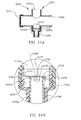
- FIG. 11A shows a cross-sectional view of yet another example of an improved endotracheal catheter, generally indicated at 900.
- the catheter 900 includes a manifold 904 and a catheter 908.
- the manifold 904 includes first, second, third and fourth ports, 912a-912d, the first and fourth of which are aligned to allow advancement of the catheter 908 through the manifold.
- An adapter 920 is disposed in the fourth port 912d and functions as a guide for the catheter 908 as it is advanced and retracted.
- the adapter 920 preferably includes a first portion 920a having an inner diameter approximately the same size as the outside diameter of the catheter 908, and a second portion 920b having a diameter which is larger than that of the first portion.
- a flap 932 is attached to the ring 936b and extends inwardly so as to be disposed perpendicular to the travel path of the catheter 908 as it is advanced through the manifold 904.
- the flap 932 preferably has a small hole 960 to allow a small amount of air through the flap 932.
- the flap 932 is pivotably attached to the ring 936b so that as the distal end 908a of the catheter 908 is withdrawn through the fourth port 912d, suction from the catheter draws the flap 932 into contact with the distal end 908a. In such a manner, the flap 932 functions as a flap valve to substantially occlude the distal end of the catheter 908.
- FIG. 11B Also shown more clearly in FIG. 11B is a catch 964 which is attached by an arm 968 to the ring 936a.
- the catch 964 is configured to engage the flap 932 to lock the flap in a desired location.
- the flap 932 As the catheter 908 is withdrawn through the fourth port 912b, the flap 932 is drawn to the distal end 908a and drawn proximally by the suction through the catheter. (Biasing could also be used).
- the end 932a of the flap 932 opposite the attachment arm 940 between the flap and the ring 936b engages the catch 964 and causes the catch to be defected out of the way (to the right in FIG. 11B ). Once the end 932e of the flap 932 has passed by the catch 964, the catch moves back into its normal position.
- the catch 964 engages the end 932a of the flap 932 and locks the flap in a proximal, closed position.
- the catheter 908 is advanced with sufficient force to cause the catch 964 to deflect out of the way.
- the flap 932 may then pivot distally and the catheter 908 advance.
- FIG. 11C there is shown an end view of the flap 932, the rings (shown jointly as 936) and associated structure.
- the flap 932 is attached to the ring 936 by two arms 948, each forming an attachment point 940.
- the opposite end 932a of the flap 932 engages the catch 964 which is attached to the ring 936 by an arm 968.
- the catch 940 effectively locks the flap 932 in a proximal position until the user forcibly advances the catheter in a distal direction, causing the catch to release the flap.
- a single arm 948 could be used with the flap 932, and multiple catches 964 could be used.
- a single ring could be used rather than the first and second rings 936a and 936b to support the flap 932 and the catch 968.
- modifications can be made to flap 932' to provide other benefits.
- the flap 932' is attached to the ring 936' by a pair of arms 948'.
- the arms 948' could be configured to bias the flap 932' into the closed position.
- the flap 932' is generally circular, but has two rounded projections 950' which extend outwardly and are spaced approximately 90 degrees apart.
- the projections serve two important purposes. First, even if the generally circular portion of the flap 932' were slightly smaller than the distal opening of the endotracheal tube (not shown), the projections 950' would prevent the flap from entering the endotracheal tube. Second, the projections 950' would cause the flap to align for air flow to continue to the patient without laying flat to cover any passage which might interfere with airflow to or from the patient,
- the aperture 960' which is formed in the generally circular portion of the flap 932'. As shown, the aperture 960' is between 0.03 and 0.04 inches in diameter. While shown as being circular or disk-shaped, those skilled in the art will appreciate, in light of the present disclosure, that other shaped apertures could also be used.
- FIG. 12A there is shown a side cross-sectional view of an improved endotracheal catheter, generally indicated at 1000.
- the improved endotracheal catheter 1000 includes a manifold, generally indicated at 1004, and a catheter 1008.
- the manifold 1004 includes first, second, third and fourth ports 1012a-1012d as set forth above.
- An adapter 1020 is disposed in the fourth port 1012d and facilitates advancement and withdrawal of the catheter through the manifold 1004. While shown as having a first portion 1020a with a smaller diameter and a second portion 1020b with a larger diameter, the adapter 1020 could be made with a uniform interior diameter- In the alternative, the wall defining the fourth port 1012d could be configured to eliminate the need for an adapter,
- a flap 1032 which is connected to a ring 1036.
- the flap 1032 extends inwardly from the ring 1036 and is configured to be disposed perpendicular to the long axis of the catheter 1008.
- the end 1032a of the flap 1032 engages a catch mechanism 1064 which extends inwardly.
- the catch mechanism 1064 is formed by at least one projection 1068 which extends proximally and inwardly from the ring 1036.
- the projection 1068 returns to its normal position and thereby locks the flap in the proximal position.
- FIG. 12C shows an end view of the ring 1036 and the flap 1032.
- the flap 1032 is attached to the ring 1036 by a single arm 1048.
- a pair of catch mechanisms 1064 in the form of projections 1068 are spaced apart at 120 degree intervals. Having the catch mechanisms 1064 spaced helps to stabilize the flap 1032 when in the locked position.
- FIG. 13A there is shown a fragmented, cross-sectional view of an alternate example of an improved endotracheal catheter, generally indicated at 1100.
- the endotracheal catheter 1100 includes a manifold, generally indicated at 1104 and a catheter 1108.
- the manifold 1104 includes first, second, third and fourth ports 1112a-1112d which enable ventilation and other procedures through the manifold.
- the adapter 1120 is configured to receive the catheter 1108 as it is advanced and retracted through the manifold 1104.
- the adapter 1120 includes a first portion 1120a wherein the interior diameter of the adapter is only slightly larger than the exterior diameter of the catheter, and a second portion 1120b wherein an open area is left around the catheter 1108.
- a flap 1132 pivotably attached to a ring 1136.
- the flap 1132 pivots to selectively occlude the distal end 1108a of the catheter 1108.
- an aperture 1160 is formed in the flap 1132.
- the flap 1132 does not engage a flange or projection on the ring 1136. Rather, the flap 1132 is provided with a projection 1132a disposed on the flap's proximal side 1132b.
- the projection 1132a has an outer diameter 1132d which is substantially the same as the inner diameter 1108b of the distal end 1108a of the catheter 1108.
- FIG. 13B there is shown a close-up view of the flap/catheter engagement of FIG. 13A -
- the proximally extending projection 1132a of the flap 1132 nests in the open distal end 1108a of the catheter 1108 to restrict airflow through the open distal end. Air flow continues, of course, through lateral openings (such as those shown in FIGs. 3A-3D ) in the catheter 1108.
- the projection 1132a of the flap 1132 can be removed from the catheter 1108 by either advancing the catheter through the fourth port 1112d and having the flap 1132 pull the projection 1132a from the catheter, or by withdrawing the catheter proximally until the projection is pulled from catheter.
- FIG. 13C there is shown a close-up view of the flap/catheter engagement of FIG. 13A with a modification to the flap 1132. While the view of FIG. 13B shows a projection which is solid except for the aperture 1160, those skilled in the art will appreciate that any configuration which enables a friction fit between the projection and the distal end 1108a of the catheter 1108 will work. Thus, in FIG. 13C , the projection 1132a is formed by an annular flange which extends proximally from the flap 1132. Other configurations may also be used.
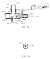
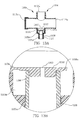
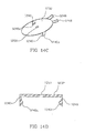
- FIG. 14A there is shown a fragmented, partially cut away, cross-sectional view of yet another alternate example of an improved endotracheal catheter, generally indicated at 1200.
- the endotracheal catheter 1200 includes a manifold, generally indicated at 1204 and a catheter 1208.
- the manifold 1204 includes first, second, third and fourth ports 1212a-1212d which function in the same manner discussed above with respect to other examples.
- An adapter 1220 is disposed in the fourth port 1212d so that the catheter 1208 reciprocates through the adapter as it is advanced into and withdrawn from the manifold 1204.
- the adapter 1220 may have a first portion 1220a defining a first diameter slightly larger than the catheter 1208 and a second portion 1220b defining a larger area around the catheter.
- a flap 1232 configured to engage the distal end 1208a of the catheter.
- the flap 1232 is typically pivotably attached by an arm 1248 to a ring 1236 which is also disposed in the fourth port 1212d.
- the flap 1232 could be directly attached to the wall defining the fourth port, or anchored in some other way.
- FIG. 14B there is shown a close-up view of the structures within the fourth port 1212d.
- the pivoting function of the flap 1232 is similar to many of the examples discussed above, in that the flap is drawn into contact with the distal end 1208a of the catheter 1208 as the catheter is withdrawn through the fourth port 1212d. Unlike the prior embodiments, however, the flap 1232 includes a pair of catches 1240 which extend proximally from the flap.
- one of the catches 1240a is disposed at the right side of the catheter 1208, while the other is made visible by the cutaway portion 1208' of the catheter. While the catches 1240 are disposed so that one catch is positioned 90 degrees from the arm and the other catch 180 degrees from the arm, it is presently understood that the preferred positioning of the catches is for them to be disposed 180 degrees from each other, which each catch being 90 degrees from the arm 1248.
- the catch 1240 engages the distal end 1208a of the catheter 1208, to form a locking mechanism wherein the flap 1232 is held to the distal end 1208a of the catheter 1208 until being forcibly removed therefrom.
- this is accomplished by using catches 1240 which are biased slightly inwardly so that a barb 1240a on the catch engages an annular groove 1208b positioned in the outer diameter of the distal end 1208a of the catheter 1208.
- catches 1240 which are biased slightly inwardly so that a barb 1240a on the catch engages an annular groove 1208b positioned in the outer diameter of the distal end 1208a of the catheter 1208.
- the flap 1232 preferably has a small hole 1248 disposed therein.
- the hole 1250 allows a small amount of airflow into the catheter 1209 through the flap.
- FIGs. 14C and 14D there is shown a perspective view, and a side view of a presently preferred embodiment of the flap 1232 shown in FIGs. 14A and 14B .
- the flap 1232 is attached to the ring (not shown) by the arm 1248, and has a pair of catches 1240 which extend proximally (downwardly as shown in the drawing) to engage the catheter (not shown) and thereby lock the flap to the catheter.
- the catches have barb 1240a configured to nest in a groove or detent in the catheter (not shown).
- the catches 1240 are positioned 180 degrees from each other, with each being 90 degrees from the arm 1248.
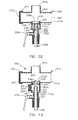
- FIG. 15A shows a cross-sectional view of an endotracheal catheter system 1300 in accordance with the present invention.
- the endotracheal catheter system 1300 includes a manifold, generally indicated at 1304 which forms a fitting for connecting the endotracheal catheter 1300 to the artificial airway (i.e., endotracheal tube) of a patient.
- the endotracheal catheter system 1300 also includes an elongate catheter 1308.
- the manifold 1304 includes a first port 1312a, a second port 1312b and a third port 1312c.
- the first port 1312a is configured to engage an artificial airway, such as an endotracheal tube.
- the second port 1312b provides inspiratory and expiratory airflow to and from the patient.
- a Y-shaped adapter is attached to the second port 1312b.
- many configurations are used in the clinical setting and those skilled in the art will appreciate the different combinations which are available.
- the third port 1312c is disposed opposite the first port 1312a and aligned so that the catheter 1308 can pass through the third port, through the manifold 1304 and through the first port into the artificial airway.
- the first and second ports 1312a and 1312b may also have swivel structures 1314 to enable the manifold 1304 to swivel with respect to adjoining structures and thereby improve patient comfort.
- a coupling or adapter 1320 Connected to the third port 1312c is a coupling or adapter 1320.
- the adapter 1320 engages the wall defining the third port 1312c.
- the inner surface of the adapter 1320 forms a chamber about the distal end 1308a of the catheter 1308. This chamber assists in cleaning the distal end of the catheter in a manner which will be discussed more fully below.
- a collar 1324 Disposed adjacent to the distal end 1320a of the adapter 1320 is a collar 1324 which has a frustoconical bore 1328 extending therethrough. (Those skilled in the art will appreciate that the collar 1324 could be formed integrally with the adapter 1320 if desired).
- the collar 1324 helps to channel the lavage solution along the catheter 1308, through the first port 1312a and into the artificial airway.
- the distal end 1324a of frustoconical bore forms an orifice in the distal end of the collar 1324.
- a flap 1340 supported by a support ring 1344 disposed in the third port 1312c selectively engages the orifice to substantially occlude the orifice when the two are engaged.
- the flap 1340 preferably has one or more holes 1348 formed therein to allow a small amount of air through the flap.
- the flap 1340 may be biased in the occluding position, or may be drawn into the occluding position by suction through the catheter 1308.
- first wiper seal 1352 Disposed at the opposing, proximal end of the collar 1324 is a first wiper seal 1352.
- the wiper seal 1352 is supported by a narrowed portion 1320b of the adapter 1320.
- the wiper seal removes major secretions.
- the adapter 1320 extends proximally and forms a cleaning chamber. Disposed adj acent a proximal end 1320c of the adapter 1320 is a second wiper seal 1356.
- the object of the second wiper seal 1356 is to remove secretions from the exterior of the catheter 1308 as it is withdrawn from the artificial airway of the patient.
- the second wiper seal 1356 will typically have a smaller diameter opening so that the second wiper seal more closely engages the exterior of the catheter 1308 than the first wiper seal.
- FIG. 15B there is shown a side cross-sectional view of the endotracheal catheter 1300 in which the catheter 1308 has been withdrawn through the manifold 1304 into a cleaning position.
- the flap 1340 closes (either due to a bias or the suction through the catheter) to occlude the opening in the collar 1324.
- the distal end 1308a of the catheter is wiped by the wiper seal 1352 so that most secretions thereon are removed.
- the secretions which are removed by the wiper seal 1352 are then carried through the catheter 1308.
- a bottle 1360 is attached to the lavage port 1330 and a cleaning liquid (typically water) is supplied through the side opening 1332 in the collar 1324.
- the cleaning liquid flows around the distal end 1308a of the catheter 1308, indicated by arrow 1364, and cleans those secretions which were not removed by the first wiper seal 1352 from the distal end of the catheter.
- the holes 1348 in the flap 1340 allow a small amount of air into the catheter, thereby facilitating removal of the secretions-
- a makeup air valve could be disposed on the side of the adapter 1320 to allow the inflow of additional air.
Landscapes
- Health & Medical Sciences (AREA)
- Pulmonology (AREA)
- Emergency Medicine (AREA)
- Engineering & Computer Science (AREA)
- Anesthesiology (AREA)
- Biomedical Technology (AREA)
- Heart & Thoracic Surgery (AREA)
- Hematology (AREA)
- Life Sciences & Earth Sciences (AREA)
- Animal Behavior & Ethology (AREA)
- General Health & Medical Sciences (AREA)
- Public Health (AREA)
- Veterinary Medicine (AREA)
- External Artificial Organs (AREA)
- Media Introduction/Drainage Providing Device (AREA)
- Infusion, Injection, And Reservoir Apparatuses (AREA)
Description
- The present invention relates to a respiratory suction catheter system with an improved mechanism for cleaning the tip of the catheter without drawing an excessive amount of air from the respiration circuit to which the endotracheal catheter is attached.
- More specifically, the present invention relates principally to a closed suction endotracheal catheter system which provides improved cleaning of the catheter while minimizing or eliminating air drawn from the patient's ventilation circuit.
- There are a variety of different circumstances under which a person may be required to have an artificial airway, such as an endotracheal tube, placed in his or her respiratory system. In some circumstances, such as surgery, the artificial airway's function is primarily to keep the patient's airway open so that adequate lung ventilation can be maintained during the procedure. In many other situations, however, the endotracheal tube will be left in the patient for a prolonged period of time. For example, with many patients, the endotracheal tube will remain in place to sustain mechanical ventilation for the life of the patient.
- If an endotracheal tube is to be left in place for any substantial amount of time, it is critical that respiratory secretions be periodically removed. This is most often accomplished with the use of a respiratory suction catheter which is advanced into the endotracheal tube. As the suction catheter is withdrawn, a negative pressure is applied to the interior of the catheter to draw mucus and other secretions from the patient's respiratory system. While a substantial amount of the mucus and other secretions will be withdrawn through the catheter lumen, a portion of the mucus and other secretions remain on the outside of the catheter.
- Because patient secretions can contain infectious agents, such as streptococcus, pseudomonus, staphylococcus and even HIV, it is important to shield clinicians from contact with the catheter. Likewise, it is important to shield patients from communicable pathogens in the environment and those which may be carried by the clinician. This is particularly important because patients on mechanical ventilation often have compromised immune systems.
- In addition to concerns of cross-contamination, suctioning a patients' artificial airway potentially interferes with proper respiration. The most common group of patients who have indwelling endotracheal tubes for prolonged periods are those who must be mechanically ventilated. Mechanically ventilated patients will typically have a fitting or manifold attached to the proximal end of the endotracheal tube (i.e., the end extending outside the patient) at an endotracheal tube hub. A pair of ventilator tubes extend from a mechanical ventilator and are typically attached to the manifold by an adapter. One tube provides inspiratory air to the patient for inhalation. The other tube allows for exhaled or expiratory air to exit the system.
- Until the 1980s, it was common to disconnect the patient from the manifold and ventilator tubes each time the patient needed to be suctioned. Interference with the air supply to the patient, even if only for a few seconds, was often unnecessarily distressing to the patient. These problems were initially overcome in the invention disclosed in
U.S. Patent No. 3,991,762 to Radford . Radford developed what is commonly referred to as a closed suction catheter system. In a closed suction catheter system, a catheter is maintained within a protective sleeve which is attached to the manifold. When suctioning is desired, the catheter is advanced through the manifold and into the artificial airway. Negative pressure is then applied to the catheter and secretions within the patient's respiratory system are evacuated. Improvements were made to the system by the invention disclosed inU.S. Patent No. 4,569,344 to Palmer . Palmer improved the system by reducing the risk of cross-contamination between the patient and the medical personnel using the device. Since that time, there has been a significant shift toward the use of closed suction catheter systems. - The advantage of closed suction catheters is that the ventilating circuit is not detached from the patient during suction procedures, as it is during open suction procedures. Because the catheter is reused a number of times over a twenty-four hour period, it is important that mucus and other secretions be cleaned from the catheter prior to periods of non-use. If the secretions are not removed, the risk of auto-contamination increases. It is also important to clean the lumen of the catheter to maintain suction efficiency.
- There are several mechanisms by which the catheter may be cleaned. First, in
U.S. Patent No. 4,569,344 , there is shown a lavage port which enables the user to inject liquid into the area surrounding the distal end of the catheter after it has been withdrawn from the patient. When liquid is injected into the closed suction catheter apparatus and suction is applied, the liquid helps to loosen and remove the secretions from the exterior of the catheter. - One significant problem with simply injecting liquid and applying suction to remove it, is that the suction also causes a volume of respiratory air to be removed through the catheter. In a "closed system," the air that is evacuated potentially disrupts the carefully controlled ventilatory cycles. Thus, the amount of respiratory air available to the patient is potentially decreased as a result of catheter cleaning. If the clinician has a hard time cleaning secretions from the catheter, suction may be applied through the catheter several times, thereby repeatedly drawing air from the ventilatory circuit.
- Other closed suction catheters have been developed to have a cleaning or lavage chamber which is physically isolated from the ventilation circuit. For example, in
U.S. Patent No. 5,487,381 to Jinotti , there is shown a closed suction catheter which has a lavage chamber configured to receive the distal tip of the catheter as it is withdrawn from the manifold. A wall is then slid from an open position to a closed position to isolate the distal end of the catheter from the manifold and the ventilation circuit. A port is commonly provided to inject lavage solution into the cleaning chamber. - One problem which is present in such a configuration is that there is a lack of air flow to allow the suction catheter to clean properly. The application of negative pressure in the catheter can create a vacuum within the chamber m the absence of sufficient air flow into the chamber. Thus, isolating the chamber inhibits free evacuation of the cleaning solution. Additionally, movement of the wall requires an extra step on the part of the clinician.
- Further, in one presently available product, the cleaning liquid commonly remains in the catheter due to the lack of airflow. Thus, contaminated liquids remaining in the catheter lumen can be reintroduced to the patient when the cleaning chamber is opened.
- Additional systems are shown in
US5775325 which discloses a two part tracheal suction system,FR2528707 WO95/14498 WO98/05371 US5490503 which discloses a suction catheter having multiple valves and a collet assembly. - In addition to the above concerns, the closed suction catheters presently available suffer from the inability to clean the catheter tip to the most desirable extent. If pathogens or other contaminants remain on the catheter for too long, they can auto-contaminate the patient. Additionally, if mucus and other secretions dry on the catheter, they can interfere with the suction efficiency, present an unsightly appearance and necessitate premature replacement of the closed suction catheter apparatus. Thus, there is a need for a catheter apparatus which has a mechanism for more effectively cleaning the distal end of the catheter without creating a substantial draw on respiratory air in the ventilation circuit
- In accordance with the present invention there is provided an endotracheal system as set forth in claim 1.
- In embodiments the present invention may provide an improved respiratory suction catheter apparatus which minimizes the amount of air drawn from the ventilation circuit during cleaning of the distal end of the catheter
- In embodiments the present invention may provide such a respiratory suction catheter apparatus which improves removal of mucus and other secretions from the distal tip of the catheter.
- In embodiments the present invention may provide such a respiratory suction catheter apparatus wherein the mechanisms for improving cleaning function automatically to separate a cleaning area from the ventilation circuit
- In embodiments the present invention may provide such a respiratory suction catheter apparatus which causes cleaning to be affected in a turbulent fluid flow.
- The present invention may provide such a respiratory suction catheter apparatus which is easy to use and relatively inexpensive
- Various examples of the above and other objects of the invention are realized in specific illustrated embodiments and examples of an improved respiratory suction catheter apparatus set forth more fully herein and claimed below The embodiments of an improved respiratory suction catheter apparatus typically include a manifold for attachment to an artificial airway, such as an endotracheal tube, to form a ventilation circuit, a catheter which is displaceable through the manifold and into the artificial airway to suction secretions from the artificial airway and lungs, and a valve mechanism disposed adjacent the ventilation circuit to minimize the air drawn from the ventilation circuit of a patient while the catheter is being cleaned
- In embodiments of the invention, the valve mechanism may be configured to automatically engage the catheter tip after it is withdrawn through the manifold to thereby minimize the amount of air drawn into the catheter during cleaning.
- In embodiments of the present invention, the valve mechanism may be configured to lock a closed position when it is pulled toward the withdrawn catheter to thereby maintain isolation between the catheter tip and the airway through the manifold.
- In embodiments of the present invention, the valve mechanism may be provided with an air makeup to allow makeup air into the catheter and thereby ensure proper evacuation of secretions and any liquid used to clean the catheter.
- In embodiments of the present invention, an air turbulence enhancing mechanism may be provided for increasing turbulent airflow around the distal end of the catheter to thereby improve removal of secretions from the catheter.
- In embodiments of the present invention, an air makeup mechanism may be disposed so as to provide makeup air to the distal end of the catheter which is not drawn from the ventilation circuit.
- In accordance with the present invention, a pair of wiper seals are used to more effectively clean the distal end of the catheter tube.
- The above and other objects, features and advantages of the invention will become apparent from a consideration of the following detailed description presented in connection with the accompanying drawings in which:
-
FIG. 1 shows a cross-sectional view of a manifold and catheter cleansing mechanism in accordance with the teachings of the prior art; -
FIG. 2 shows a cross-sectional view of a manifold and catheter cleaning mechanism in accordance with the teachings of another embodiment of the prior art; -
FIG. 3A shows a cross-sectional view of the manifold and distal portion of a catheter of an improved respiratory suction catheter apparatus with a valve member in an open position. -
FIG. 3B shows a cross-sectional view of the manifold and catheter portion shown inFIG. 3A , with the valve in a second, closed position; -
FIG. 3C shows a fragmented, close-up cross-sectional view of one embodiment of the improved respiratory suction catheter apparatus shown inFIG. 3A ; -
FIG. 3D shows a fragmented, close-up cross-sectional view of another embodiment of the improved respiratory suction catheter apparatus shown inFIG. 3A ; -
FIG. 3E shows a cross-sectional view similar to those shown inFIGs. 3A through 3D of an alternate embodiment wherein the flap engages the collar; -
FIG. 4A shows a fragmented, cross-sectional view of an alternative improved respiratory suction catheter apparatus having a valve in an open position. -
FIG. 4B shows a fragmented, cross-sectional view of the apparatus ofFIG. 4A , wherein the valve is in a closed position to isolate the catheter from the ventilation circuit; -
FIG. 4C shows a fragmented, cross-sectional view of the apparatus ofFIGs. 4A and4B , with an air makeup mechanism in an open position to facilitate sectioning of mucus and the like; -
FIG. 5A shows a fragmented, cross-sectional view of an alternative improved respiratory suction catheter apparatus having a valve in an open position. -
FIG. 5B shows a fragmented, cross-sectional view of the apparatus shown inFIG. 5A with the valve in a closed position; -
FIG. 5C shows a partial cross-sectional view of the valve of the apparatus shown inFIGs. 5A and 5B ; -
FIG. 6A shows a fragmented, cross-sectional view of yet another alternative improved respiratory suction catheter apparatus. -
FIG. 6B shows a fragmented, cross-sectional view of the apparatus shown inFIG. 6A in a closed configuration; -
FIGs. 6C and 6D show end views of the valve mechanism of the apparatus shown inFIGs. 6A and 6B in a relaxed position and with a catheter extending therethrough, respectively; -
FIG. 7A shows a fragmented, cross-sectional view of still another improved respiratory suction catheter apparatus; -
FIG. 7B shows a partial end view of the improved respiratory suction catheter apparatus ofFIG. 7A in a closed position; -
FIG. 8A shows a fragmented, cross-sectional view of still yet another improved respiratory suction catheter apparatus. -
FIG. 8B shows a fragmented, cross-section view of the improved endotracheal catheter ofFIG. 8A , wherein the valve mechanism is in a closed configuration; -
FIG. 9A shows a fragmented, cross-sectional view of an improved endotracheal catheter wherein the valve mechanism locks in a closed position; -
FIG. 9B shows a close-up view of the locking valve mechanism and associated structure ofFIG. 9A . -
FIG. 10A shows a fragmented, cross-sectional view of an alternate improved endotracheal catheter with a locking valve mechanism; -
FIG. 10B shows a close-up view of the locking valve mechanism and associated structure ofFIG. 10A ; -
FIG. 11A shows a fragmented, cross-sectional view of another improved endotracheal catheter which has a locking valve mechanism disposed thereon; -
FIG. 11B shows a close-up view of the locking valve mechanism and associated structure ofFIG. 11A ; -
FIG. 11C shows a close-up end view of the locking valve mechanism ofFIGS. 11A and 11B ; -
FIG. 11D shows a close-up end view of an alternate of the flap shown inFIG. 11C ; -
FIG. 12A shows a fragmented, cross-sectional view of yet another improved endotracheal catheter which has a locking mechanism disposed thereon; -
FIG. 12B shows a close-up view of the locking valve mechanism and associated structure ofFIG. 12A ; -
FIG. 12C shows a close-up end view of the locking valve mechanism ofFIGs. 12A and 12B ; -
FIG. 13A shows a fragmented, cross-sectional view of an alternate endotracheal catheter with a locking valve mechanism; -
FIG. 13B shows a close-up view of the locking valve mechanism and associated structure ofFIG. 13A ; -
FIG. 14A shows a fragmented, cross-sectional view of an alternate improved endotracheal catheter with a locking valve mechanism; -
FIG. 14B shows a close-up view of the locking valve mechanism and associated structure ofFIG. 14A ; -
FIG. 14C shows a perspective view of the flap shown inFIGs. 14A and 14B ; -
FIG. 14D shows a side view of the flap shown inFIGs. 14A through 14C . -
FIG. 15A shows a fragmented, cross-sectional view of an improved endotracheal catheter in accordance with the present invention in which a pair of wiper seals are used to enhance cleaning of the distal end of the catheter tube; and -
FIG. 15B shows a cross-sectional view similar to that ofFIG. 15A , but with the catheter tube pulled back into a proximal position. - Reference will now be made to the drawings in which the various elements of the present invention will be given numeral designations and in which the invention will be discussed so as to enable one skilled in the art to make and use the invention. It is to be understood that the following description is only exemplary of the principles of the present invention, and should not be viewed as narrowing the pending claims. Those skilled in the art will appreciate that aspects of the various embodiments discussed may be interchanged and modified without departing from the scope of the invention.
- Referring to
FIG. 1 , there is shown a cross-sectional view of a manifold 10 andcatheter cleansing mechanism 14 in accordance with the teachings of the prior art. The manifold has a valve mechanism in the form of arotatable rod 18 for selectively isolating alavage chamber 20 from theventilation circuit 26. When the distal end of thecatheter 22 is disposed in thelavage chamber 20, a lavage solution can be injected through aside port 30 to help wash the mucus and other secretions from the exterior of thecatheter 22. Because of the relative size and dimensions of thelavage chamber 20, however, there is nothing to force vigorous interaction between the lavage solution and the secretions on the exterior of the catheter. Additionally, because the lavage chamber is not configured for makeup air to enter when therotatable rod 18 is closed, a vacuum can be created in thelavage chamber 20 which interferes with effective suctioning. - An additional disadvantage of the embodiment shown in
FIG. 1 is that the closure mechanism for such devices typically must be manually activated. If the user fails to close therotatable rod 18, actuation of suction through the catheter will draw air from theventilation circuit 26. - Turning now to
FIG. 2 , there is shown a cross-sectional view of an alternative embodiment of the prior art. The manifold 100 is provided with a plurality ofports 104. Afirst port 104a is attached to the hub of an endotracheal tube of the patient to conduct respiratory air to and from the endotracheal tube. Thus, the manifold forms part of a ventilation circuit. The air is typically provided to and removed from the manifold through asecond port 104b which is attached to a pair of ventilation tubes via a connector (not shown). The ventilation tubes are, in turn, connected to a mechanical ventilator (not shown) in a manner which will be well known to those skilled in the art. - A
third port 104c is provided opposite thesecond port 104b. Thethird port 104c is typically covered with acap 108 which is removed when "blow-by" is desired to wean a patient from forced ventilation. - The manifold also has a
fourth port 104d. Acoupling 112 is configured to form a force-fit engagement with thefourth port 104d and effectively connects thecatheter 116 and aprotective sleeve 120 to themanifold 100. Disposed adjacent a proximal end of thecoupling 112 is alavage port 124 through which a cleaning liquid can be injected to rinse the exterior of thecatheter 116. Such a configuration is advantageous because thelavage port 124 is positioned adjacent aseal 128 which is configured to wipe mucus and other secretions from thecatheter 116 as is drawn through the seal. Thus, a user will typically withdraw thecatheter 116 until thedistal end 116a thereof is positioned slightly distally of theseal 128, and then the cleaning solution will be injected into thelavage port 124 to assist in the removal of secretions. While such a method of removing the secretions is generally effective, it can draw more air from theventilation circuit 132 than is necessary to effectively clean thedistal end 116a of thecatheter 116. Additionally, it is common for respiratory therapists and other clinicians to maintain the suction on as thedistal end 116a of thecatheter 116 is drawn from thefirst port 104a to a position immediately adjacent theseal 128. - Turning now to
FIG. 3A , there is shown a cross-sectional view of a portion of an improved endotracheal catheter, generally indicated at 200. The endotracheal catheter includes a manifold, generally indicated at 204 and acatheter 208. The manifold 204 includes a plurality ofports 212a-c. Afirst port 212a is configured for attachment to the proximal end of an artificial airway, such as the hub of an endotracheal tube, tracheostomy tube, etc. Asecond port 212b is typically connected to a pair of ventilator tubes (not shown) by means of an adaptor (not shown), in accordance with common practice in the art. - As used herein, distal refers generally to the direction of the patient, while proximal refers to the direction of the user. Unless otherwise noted, the drawings of
FIG. 2A are oriented such that the distal (patient) end is toward the top of the page, while the proximal (user) end is toward the bottom of the page. - During normal usage, conditioned inspiratory air is forced through one of the ventilator tubes, through the
second port 212b and thefirst port 212a and into the patient's lungs via the artificial airway. Exhaled air is carried through thefirst port 212a and then thesecond port 212b and out through the other ventilator tube. Thus, the manifold 204 forms part of aventilation circuit 214 through which respiratory air is cycled. Also forming part of the manifold 204 is athird port 212c. Thethird port 212c is typically covered by acap 216. - Whenever mechanical ventilation is used, it is the goal to someday return the patient to voluntary or spontaneous breathing. To accomplish this, the patient must usually be weaned from the mechanical ventilation to spontaneous breathing. To this end, the
cap 216 may be removed from thethird port 212c so that oxygenated air is passed by the patient's endotracheal tube, but inspiratory air is not forced into the patient's lungs by means of a totally closed circuit. This situation, commonly called "blow-by," enables the patient to gradually resume natural or spontaneous breathing. - The manifold 204 also has a
fourth port 212d. Thefourth port 212d is disposed generally opposite thefirst port 212a and is configured to allow thecatheter 208 to slide therethrough and into the first port to enable suctioning of the patient. At the completion of suctioning, thecatheter 208 is pulled back into thefourth port 212d to prevent interference with theventilation circuit 214. - Disposed between the wall forming the
fourth port 212d and thecatheter 208 is a coupling oradapter 220. On an outer extreme, theadapter 220 engages the wall defining thefourth port 212d. On an inner extreme, theadapter 220 engages acollar 224 which closely surrounds thecatheter 208 so as to leave a smallcylindrical space 226 around thecatheter 208. Ideally the space between thecatheter 208 and thecollar 224 is between 0.005 and 0.015 inches (between 0.127 and 0.381 mm). This proximity provides two important advantages. First, iflavage needs to be provided to the lungs of the patient, injecting lavage solution through thelavage port 228 and into thecylindrical space 226 causes a stream of lavage solution to be directed out thedistal end 224a of the collar and through thefirst port 212a. If the spacing between thecatheter 208 and thecollar 224 is too large (as in the art discussed above), the lavage solution cannot be thus directed. Second, as thecatheter 208 is drawn back into thecollar 224 after use, the collar helps to wipe any heavy layers of mucus or other secretions from the outside of the catheter. - Injecting lavage/cleaning solution through the
lavage port 228 further removes the secretions from the exterior of thecatheter 208 and enhances evacuation by suction in the catheter. This configuration also minimizes the volume of air and cleaning solution necessary to effect cleaning. - While the
collar 224 configuration shown inFIG. 3A is beneficial, it is still common to have secretions build up on thedistal end 208a of thecatheter 208. If such build up is not promptly removed, it can interfere with the ability of the catheter to properly suction the patient. It can also serve as a culture medium for pathogens within the closed suction catheter system. - It has been found that selective obstruction of the airflow into the
distal end 208a of thecatheter 208 significantly improves catheter cleaning. Additionally, it has been found that such a mechanism for improved cleaning also minimizes the withdrawal of air from theventilation circuit 214. - As shown in
FIG. 3A , aflap 232 is hingedly attached to anannular ring 236 disposed inside thefourth port 212d so as to enable theflap 232 to pivot with respect to the ring to form a self-closing valve member. Of course, theflap 232 could be attached directly to the wall of the manifold 204 defining thefourth port 212d or to theadapter 220. The hingedattachment 240 allows theflap 232 to selectively move while maintaining alignment with the catheter tip, thereby creating a self-closing flap valve. - As shown in
FIG. 3B , theflap 232 is positioned to align with thedistal end 208a of thecatheter 208 when the catheter is almost completely withdrawn into thecollar 224. The hingedattachment 240 is sufficiently flexibly that suction through thedistal end 208a of thecatheter 208 will draw theflap 232 proximally from a first, distal position into a second, proximal position, wherein the flap contacts with the distal end of the catheter. Thus, theflap 232 and related structures form a self-closing valve wherein no additional external manipulation of the catheter system is needed to close the valve. - As with most closed suction catheters, the
catheter 208 includes aprimary aperture 244 in thedistal end 208a and one or morelateral apertures 248 positioned slightly proximal from the distal end. When theflap 232 moves proximally and contacts thedistal end 208a of thecatheter 208, suction throughcatheter tip aperture 244 is dramatically reduced or eliminated. Decrease in suction flow through theaperture 244 causes increased suction flow in thelateral apertures 248, thereby increasing the ability of the lateral apertures to evacuate any secretions contained between the outside of thecatheter 208 and the interior of thecollar 224. Because thelateral apertures 248 are generally smaller than thedistal aperture 244 and because airflow to the lateral apertures is limited by thecollar 224, a substantial decrease in the amount of air drawn from the ventilation circuit is achieved while simultaneously improving cleaning of thecatheter 208. - As shown in
FIGs. 3A and 3B , theproximal side 232a (i.e., the side opposite the ventilation circuit 214) of theflap 232 is generally planar. In such a configuration, theproximal side 232a of theflap 232 will typically form a substantially complete seal with thedistal end 208a of thecatheter 208. - Turning now to
FIG. 3C , there is shown a close-up cross-sectional view of the example shown inFIGs. 3A and 3B with a slight modification to theflap 232. Unlike theflap 232 inFIGs. 3A and 3B which is substantially planar, the flap 232' inFIG. 3C has achannel 252 formed therein on theproximal side 232a'. Thechannel 252 prevents the flap 232' from forming an airtight engagement with thedistal end 208a of thecatheter 208. In other words, thechannel 252 ensures that a measured volume of air will be drawn into theaperture 244 at the distalmost end 208 of the catheter. - The measured volume of air which is drawn in through the
channel 252 can have an important effect. Specifically, the air creates turbulent airflow both within thecatheter 208 and immediately around its exterior. The turbulent airflow in turn, assists in breaking up agglomerations of mucus and secretions which lavage/cleaning solution alone may not. Thus, the turbulent airflow helps to provide improved cleaning of thedistal end 208a of thecatheter 208. This is in sharp contrast to many of the prior art devices which have advocated the use of a lavage/cleaning chamber to clean the exterior of the catheter. Because the lavage/cleaning chamber is usually substantially larger than the catheter or because makeup air is not specifically provided, it is difficult to create turbulent airflow within the chamber. Without turbulent airflow, the mucus and other secretions are often not removed from the exterior of the catheter. - Turning now to
FIG. 3D , there is shown yet another variation of theflap 232 shown inFIGs. 3A and 3B . Rather than having a channel formed in a proximal side thereof, theflap 232" has an aperture 260 formed therein so as to allow a relatively small amount of air to pass through theflap 232". As with the apparatus ofFIG. 3C , the small hole creates turbulent airflow at thedistal end 208a of thecatheter 208 and thereby improves cleaning. It is currently believed that an aperture 260 in theflap 232" with a diameter of about 0.03 inches (0.762 mm) is preferred. - While shown in
FIGs. 3A through 3D as engaging thedistal end 208a of thecatheter 208, theflap 232 forming a flap valve need not engage the catheter itself. Thus, for example,FIG. 3E shows an example similar to those shown inFIGs. 3A through 3D , except that theflap 232 is disposed to engage thedistal end 224a of thecollar 224 rather than thedistal end 208a of thecatheter 208. In such a configuration, suction flow can still be achieved through theaperture 244 at thedistal end 208a of thecatheter 208. - Preferably, a source ofmakeup air will be provided. This can be accomplished by using either of the flap configurations shown in
FIGs. 3C and 3D . In the alternative, a small hole can be formed in thecollar 224 to facilitate a small amount of makeup air being present to enhance suction flow and to increase turbulence. - Regardless of which configuration of those shown in
FIGs. 3A through 3E is used, the result is an improved ability to clean thedistal end 208a of thecatheter 208, while at the same time significantly reducing the amount of air which is withdrawn from theventilation circuit 214. Thus, consistent ventilation is provided to the patient, and the clinician is able to more easily clean thecatheter 208. - Turning now to
FIG. 4A , there is shown another embodiment of an improved respiratory suction catheter apparatus, generally indicated at 300. The improved respiratorysuction catheter apparatus 300 includes a manifold 304 and acatheter 308. As with the previous embodiment, the manifold 304 includes afirst port 312a, asecond port 312b, athird port 312c and afourth port 312d. - An
adapter 320 is disposed in thefourth port 312d in such a manner as to make the manifold 304 and thecatheter 308 a functionally integrated unit. Theadapter 320 may be adhesively attached to the manifold 304, or may be simply force-fit. - Unlike the example discussed with
FIGs. 3A through 3D , an annular ring is not disposed in the manifold 304 independent of theadapter 320. Rather, anannular ring 326 extends inwardly from adistal end 320a of theadapter 320. Theannular ring 326 defines an aperture oropening 330 through which thecatheter 308 can be extended. Thus, theopening 330 is slightly larger than the exterior of thecatheter 308. - Also extending inwardly from the
adapter 320 is aflap 336. Theflap 336 is preferably hingedly attached to either the adapter directly or to theannular ring 326. When no suction is applied to thecatheter 308, or when thedistal end 308a of the catheter is disposed distally from theflap 336, the flap will generally extend distally from theannular ring 326 and provide virtually no resistance to advancement of thecatheter 308. - As shown in
FIG. 4B , as thedistal end 308a of thecatheter 308 is withdrawn through theannular ring 326 while suction is applied, a vacuum is created which pulls theflap 336 over theopening 330, thereby isolating thedistal end 308a of thecatheter 308 from theventilation circuit 340 and preventing the catheter from drawing air away from a patient to whom the manifold is attached. While theflap 336 could be configured in the manner shown inFIGs. 3C and 3D , the present configuration does not necessitate the use of makeup air from theventilation circuit 340. - If the
catheter 308 were simply left in thechamber 348 behind theflap 336/annular ring 326 and lavage were injected into the chamber, a substantial negative pressure could build within the chamber. Additionally, because no relief is provided, it would be difficult to suction mucus etc. from the chamber once the lavage source had been sucked dry. To overcome these problems with the prior art, the embodiment inFIGs. 4A through 4C has a makeup air inlet, generally indicated at 350 which is formed in a portion of the wall defining thefourth port 312d of the manifold and theadapter 320. Themakeup air inlet 350 preferably includes afilter 354 which is selected to substantially prevent cross-contamination between the environment/clinicians and the patient. Disposed adjacent to the filter material is aflexible barrier 358 which forms a one-way valve 360. - As shown in
FIGs. 4B and 4C , the one-way valve 358 will generally be closed when thecatheter 308 is in an extended position, wherein the catheter extends through theopening 330 in theannular ring 326. However, once thedistal end 308a of thecatheter 308 has been withdrawn through theopening 330 in theannular ring 326 and theflap 336 has been drawn closed, a vacuum will quickly develop on the side of theflap 336 opposite theventilation circuit 340. The vacuum causes the one-way valve 358 to open and allow a supply of makeup air to enter the chamber. The makeup air flowing past the flexible one-way valve member 358 helps to create turbulent airflow and facilitate removal of any respiratory secretions on thecatheter 308. This is preferably accomplished at about the same time the user utilizes thelavage port 370 to inject lavage/cleaning solution through thespace 372 between thecollar 374 and thecatheter 308. It will be appreciated that the one-way valve 358 could be configured to provide very little resistance to air inflow, or could be configured to require a substantial vacuum to be present before makeup air is allowed into the area proximal theflap 336. - Turning now to
FIG. 5A , there is shown a fragmented, cross-sectional view of an alternative example of an improved respiratory suction catheter apparatus, generally indicated at 400. The respiratory suction catheter apparatus includes a manifold 404 and acatheter 408 which is moveable through the manifold to suction secretions from a patient's lungs. As with the previously discussed examples, the manifold includes afirst port 412a for attachment to an endotracheal tube or other artificial airway, asecond port 412b for attachment to the ventilator tubes of a mechanical ventilator, athird port 412c which is covered with acap 416, and afourth port 412d which receives the connector oradaptor 420. - Disposed at the
distal end 420a of theadaptor 420 is avalve 424 in a configuration which is commonly referred to as a duckbill valve. Thevalve 424 is formed by a piece of resilient material which opens as thecatheter 408 is advanced therethrough, and closes when the catheter is withdrawn. Thevalve 424 is attached to theadaptor 420 by aflexible base 428. - Also disposed in the
adaptor 420 is anair inlet 432 which includes afilter material 436 and aresilient member 440 configured to form a one-way valve 444 similar to that discussed in the previous example. While duckbill valves have been used in endotracheal catheter systems in the past, thevalve 424 shown inFIGs 5A through 5C is substantially advanced in several respects. First, as shown inFIGs. 5A and 5C , the interior of thevalve 424 hashelical grooves 450 formed therein. Thehelical grooves 450 help to create turbulent airflow around thedistal end 408a of thecatheter 408. Additionally, theflexible base 428 is configured to allow thevalve 420 to be drawn toward thecollar 460 to thereby reduce space and improve removal of secretions from the exterior of thecatheter 408. - Turning now specifically to
FIG. 5B , there is shown a cross-sectional view similar to that shown inFIG. 5A , but with thedistal end 408a of thecatheter 408 in a retracted position. Once thedistal end 408a of thecatheter 408 is withdrawn proximally from thevalve 424, the suction through the catheter works against theflexible base 428 of the valve and draws the valve toward thecollar 460. A pair ofair inlets 470 are disposed at thebase 428 of thevalve 424 and allow air into the valve. - Applying suction to the
valve 424 and through theair inlets 470 as shown inFIG. 5B creates a vacuum between theadaptor 420 and theflexible base 428, thereby causing the one-way valve 444 to open and allow air into theair inlets 470 at the top of thecollar 460. This air mixes with the water injected through thelavage port 480 and turbulently travels along thedistal end 408a of thecatheter 408. The turbulent motion of the air/water mixture is enhanced by thehelical grooves 450. - Once suction through the
catheter 408 is stopped, there is no longer a negative pressure from the catheter to keep the one-way flap valve 444 closed, or to maintain thevalve 444 adjacent to the distal end of the collar. Thus, thevalve 424 may return to the position shown inFIG. 5A , except that it will be closed as thecatheter 408 remains substantially in the collar until the next use. - Turning now to
FIG. 6A , there is shown a cross-sectional view of yet another alternative example of an improved endotracheal catheter made in accordance with the principles of the present invention. The endotracheal catheter 00 includes a manifold 504 and acatheter 508. The manifold 504 has afirst port 512a for attachment to the hub of an artificial airway of a patient, and asecond port 512b for attachment to the ventilator tubes (not shown) of a mechanical ventilator so as to define aventilation circuit 516. - The manifold also includes a
third port 512c which is configured to receive thecatheter 508. Disposed in thethird port 512c are a pair of floating flexible disks ormembranes opening catheter 508 may be slid. An end view of thedisks FIG. 6D . - When the
catheter 508 is withdrawn through theopenings disks catheter 508, as shown inFIG. 6B . This substantially seals the two disks together in an arrangement without overlapping openings as shown inFIGS. 6B and 6C . This configuration minimizes or eliminates (depending on the seal) air flow out of the ventilation circuit as lavage solution is injected through thelavage port 540 and thedistal end 508a of thecatheter 508 is cleaned. - Because the
lavage port 540 is disposed behind thedisks second lavage port 550 can be added distally from the disks. Thesecond lavage port 550 typically would not be used for cleaning of thecatheter 508. - Turning now to
FIG. 7A there is shown a cross-sectional view of still another example of an improved endotracheal catheter. Most portions of the endotracheal catheter shown inFIG. 7A are the same as those discussed with respect toFIGs. 6A through 6D and are numbered accordingly. The one major difference between the examples ofFIGs. 6A through 6D andFIG. 7A is that thedisks resilient closing membrane 570 which is attached at oneend 570a to the manifold 504 and at anopposing end 570b to anadapter 572 holding thecatheter 508. Theadapter 572 ormanifold 504 can be rotated to twist themembrane 570 and thereby either reduce or enlarge the size of a hole 580 (FIG. 7B ) formed by the material. By twisting theresilient material 570 to close thehole 580, the drawing of air from theventilation circuit 516 can be reduced or even eliminated. - When suctioning of a patient is desired, the
resilient material 570 is rotated to allow the catheter to pass therethrough. Becauseswivels 5 74 are disposed on the first andsecond ports ventilation circuit 516 when thedistal end 508a of thecatheter 508 is being cleaned. -
FIG. 7B shows an end view of theresilient membrane 570. By rotating theresilient membrane 570 in one direction, thehole 580 is enlarged. By rotating the resilient material in an opposing direction, the size of thehole 580 is reduced. - Turning now to
FIGs. 8A and 8B , there is shown yet another endotracheal catheter The respiratorysuction catheter apparatus 600 includes a manifold 604 and acatheter 608 which is moveable through the manifold. As with many of the examples discussed previously, the manifold 604 incudes afirst port 612a for connection to the hub of an endotracheal tube, asecond port 612b for connection (via ventilator tubes) to a mechanical ventilator, and a third port 612e and cap 616 which can be used for blow-by. - The
fourth port 612d is different from those discussed previously because it has ashroud 620 placed therein. Theshroud 620 is attached to aplunger 624 so as to allow the user to move the shroud between a first position adjacent the sidewall of thefourth port 612d (FIG. 8A ) and a second position (FIG. 8B ) wherein the shroud is disposed approximately at the center ofport 612d. - During use of the respiratory
suction catheter apparatus 600, theshroud 620 will typically be moved into the first position so that it does not interfere with advancement of thecatheter 608 through the manifold 604, Once suctioning has been completed, thecatheter 608 is withdrawn into thecollar 634. Theplunger 624 is then pressed so as to move theshroud 620 over thedistal end 634a of thecollar 634 to cover thedistal end 608a of thecatheter 608. Typically, thecatheter 608 will then be advanced toward thedistal end 620a of theshroud 620. Lavage/cleaning solution will then be applied through thelavage port 640 while suction is applied. - If desired, a small gap can be formed between the
shroud 620 and thecollar 634 to ensure turbulent airflow into thedistal end 608a of thecatheter 608. Likewise, grooves or some other pattern may be formed in the shroud to encourage turbulent airflow. Additionally, a valve member may be included to allow for makeup air in a similar manner as discussed with several of the examples above. - Turning now to
FIG, 9A , there is shown a fragmented, cross-sectional view of an alternate example of an improved endotracheal catheter system, generally indicated at 700, incorporating aspects of the present invention. The endotracheal catheter system includes a manifold, generally indicated at 704, and acatheter 708. As with several of the previous examples, the manifold 704 includes a plurality ofports 712a-712d. Thefirst port 712a is configured for attachment to the proximal end of an artificial airway, such as the hub of an endotracheal tube, tracheostomy tube, etc. Asecond port 712b is typically connected to a pair of ventilator tubes (not shown) by means of an adaptor (not shown), in accordance with common practice in the art. During normal usage, conditioned inspiratory air is forced through one of the ventilator tubes, through thesecond port 712b and thefirst port 712a and into the patient's lungs via the artificial airway. Exhaled air is carried through thefirst port 712a and then thesecond port 712b and out through the other ventilator tube. Thus, the manifold 704 forms part of aventilation circuit 714 through which respiratory air is cycled. - Also forming part of the manifold 704 is a
third port 712c. Thethird port 712c is typically covered by a cap 716 which may be removed to facilitate "blow-by" and thereby enable the patient to gradually resume spontaneous breathing. Those skilled in the art will appreciate that while the provision of a third port for blow-by is preferred, it is not necessary to the practice of the principles of the invention. Thus, a manifold similar to that shown inFIGs. 6A and7A or some other manifold configuration could be used. - The manifold 704 also has a
fourth port 712d. Thefourth port 712d is disposed generally opposite thefirst port 712a and is configured to allow thecatheter 708 to slide therethrough and into the first port to enable suctioning of the patient. At the completion of suctioning, thecatheter 708 is pulled back into thefourth port 712d to facilitate cleaning and to prevent interference with theventilation circuit 714. - Disposed between the wall forming the
fourth port 712d and thecatheter 708 is a coupling oradapter 720. On an outer extreme, theadapter 720 engages the wall defining thefourth port 712d. On an inner extreme, theadapter 720 engages thecatheter 708. (If desired a collar, such as that shown inFIG. 3A at 224, could be used between thecatheter 708 and the adapter 720). - The
adapter 720 preferably has a cylindrical hollow which forms afirst portion 720a disposed toward a proximal end thereof, and asecond portion 720b disposed toward a distal end thereof. At thefirst portion 720a, the diameter of the cylindrical hollow is substantially the same as the outer diameter of thecatheter 708 so that thefirst portion 720a of theadapter 720 closely surrounds the catheter. - The
second portion 720b of the adapter's cylindrical hollow has a larger diameter than thefirst portion 720a. This larger diameter forms a collection area in which mucus and other secretions can collect as thecatheter 708 is drawn proximally through theadapter 720. - As has been mentioned previously, it has been found that selective obstruction of the airflow into the
distal end 708a of thecatheter 708 can significantly improve catheter cleaning. Additionally, it has been found that such a mechanism for improved cleaning also minimizes the withdrawal of air from theventilation circuit 714. - As shown in
FIG. 9A , aflap 732 is hingedly attached to anannular ring 736 disposed inside thefourth port 712d so as to enable theflap 732 to pivot with respect to the ring. Of course, theflap 732 could be attached directly to the wall of the manifold 704 defining thefourth port 712d or to theadapter 720. The hinged attachment 740 allows theflap 732 to selectively move while maintaining alignment with thedistal end 708a of thecatheter 708, thereby creating a flap valve. - Disposed in the
flap 732 is anaperture 760 which is positioned to provide a small amount of air into the interior of thedistal end 708a of thecatheter 708, As with previous examples theaperture 760 provides a small amount of air into thecatheter 708 to facilitate cleaning without drawing excessive air from the inhalation circuit of the patient. - With the
flap 732 occluding airflow into thedistal end 708a of thecatheter 708, increased suction is applied to thelateral openings 738 which are formed in the catheter proximal from the distal end. The increased suction, in turn, creates improved cleaning of thecatheter 708. - One significant difference between the
flap 732 and those shown in previous examples is the manner in which it engages thering 736. On one end, theflap 732 is pivotably attached to thering 736 to enable movement as a flap valve as discussed above. At an opposing end, theflap 732 is configured to engage aflange 764 which extends inwardly from thering 736. More specifically, the ends of theflap 732 and theflange 764 are configured to complement one another so as to nest in one another or otherwise form a locking engagement. Thus, as shown more clearly inFIG. 9B , theend 764a of theflange 764 is provided with a V-shaped groove and thecomplimentary end 732a of theflap 732 is a V-shaped projection. - As the
catheter 708 is withdrawn through theadapter 720 to the point where thedistal end 708a of the catheter is disposed behind thering 736, the suction of air through the tube will cause theflap 732 to be pulled into contact with the distal end of the catheter and thereby improve cleaning of the catheter as has been discussed with previous examples. Once thecatheter 708 is sufficiently withdrawn through theadapter 720, theend 732a of theflap 732 will nest in the groove in theend 764a of theflange 764, thereby locking the flap in a closed position. With theflap 732 locked closed, the risk of mucus or other materials coming back into theventilation circuit 714 is significantly reduced. - Thus, the engagement between the
flap 732 and theflange 764 provides a locking mechanism which preventsflap 732 from being moved from the closed position (FIG. 9B ) to the open position wherein theflap 732 does not interfere with distal movement of thecatheter 708. With some of the prior examples, the only mechanism for maintaining theflap 732 in the closed position is via suction. In contrast, the present example provides a positive retention of theflap 732 in the closed position. - When the next suctioning procedure is desired, the
flap 732 can be opened by advancing thedistal end 708a of thecatheter 708 and forcing theend 732a of the flap out of engagement with theflange 764. The amount of force required is minimal above that normally exerted to advance the catheter for suctioning. - While not shown in
FIGs. 9A and 9B , a lavage port could be used with theadapter 720 to enhance cleaning of thecatheter 708. The lavage port could be placed along either the first or second portions, 720a and 720b, depending on the tolerances thereof. - Turning now to
FIG. 10A , there is shown a fragmented, cross-sectional view of an alternate example of an improved endotracheal catheter system, generally indicated at 800. As with the previous example, the endotracheal catheter system includes a locking valve mechanism, generally indicated at 810. - The
endotracheal catheter 800 includes a manifold, generally indicated at 804 and thecatheter 808. The manifold includes first, second, third andfourth ports 812a-812d which define aventilation circuit 814 and otherwise function in the same manner as the first throughfourth ports 712a-712d discussed above. - An
adapter 820 is disposed in thefourth port 812d in a manner similar to that discussed with respect to the prior example. Theadapter 820 may include first andsecond portions - Also disposed in the
fourth port 812d is aflap 832 which is configured to engage the distal end 808a of thecatheter 808. Theflap 832 is pivotably attached to aring 836 disposed in thefourth port 812d. (Of course, theflap 832 could be directly connected to the wall defining thefourth port 812d). As with several of the previously discussed examples, theflap 832 is drawn into contact with the distal end 808a of thecatheter 808 as suction is applied through the catheter and the catheter is drawn proximally through theadapter 820. Preferably, anaperture 860 is formed in theflap 832 so that the flap provides resistance to airflow into the distal end 808a of thecatheter 808 without completely terminating airflow. The reduced airflow improves cleaning, while complete lack of airflow can inhibit the same. The size of theaperture 860 is preferably about 0.03 inches (0.762 mm) in diameter. - Also disposed on the
ring 836 is an inwardly extendingprojection 864 which forms a catch. Preferably, theprojection 864 is disposed on thering 836 opposite the location at which theflap 832 is attached to the ring. (As with theflap 832, the projection could also be directly mounted on in thefourth port 812d). - As the
flap 832 is drawn proximally by suction through thecatheter 808, the flap passes over theprojection 864 which extends inwardly slightly further than theend 832a of the flap. Thus, once theflap 832 has moved proximally beyond the extreme inward point of theprojection 864, distal movement of the flap is restricted by the projection. Thus, theflap 832 becomes frictionally engaged behind theprojection 864 until it is forced distally past the projection by advancement of thecatheter 808. (While discussed above as requiring suction, those skilled in the art will appreciate that the flap 832 (etc.) could be configured to bias the flap into the proximal or closed position). - Referring specifically to
FIG. 10B , there is shown a close-up view of the locking valve mechanism and locking structure discussed above. As shown, theend 832a of theflap 832 is tapered to apoint 832b which is formed on the distal side of the flap. Theprojection 864 tapers toward a point disposed at theproximal end 864a thereof. Such a configuration enables theend 832a of theflap 832 to slide proximally over theprojection 864, while requiring additional effort to move the flap distally past the projection. -
FIG. 11A shows a cross-sectional view of yet another example of an improved endotracheal catheter, generally indicated at 900. Thecatheter 900 includes a manifold 904 and acatheter 908. The manifold 904 includes first, second, third and fourth ports, 912a-912d, the first and fourth of which are aligned to allow advancement of thecatheter 908 through the manifold. - An
adapter 920 is disposed in thefourth port 912d and functions as a guide for thecatheter 908 as it is advanced and retracted. Theadapter 920 preferably includes afirst portion 920a having an inner diameter approximately the same size as the outside diameter of thecatheter 908, and asecond portion 920b having a diameter which is larger than that of the first portion. - Also disposed in the
fourth port 912d is a pair ofrings flap 932 is attached to thering 936b and extends inwardly so as to be disposed perpendicular to the travel path of thecatheter 908 as it is advanced through themanifold 904. Theflap 932 preferably has asmall hole 960 to allow a small amount of air through theflap 932. - Referring more specifically to
FIG. 11B , theflap 932 is pivotably attached to thering 936b so that as thedistal end 908a of thecatheter 908 is withdrawn through thefourth port 912d, suction from the catheter draws theflap 932 into contact with thedistal end 908a. In such a manner, theflap 932 functions as a flap valve to substantially occlude the distal end of thecatheter 908. - Also shown more clearly in
FIG. 11B is acatch 964 which is attached by anarm 968 to thering 936a. Thecatch 964 is configured to engage theflap 932 to lock the flap in a desired location. As thecatheter 908 is withdrawn through thefourth port 912b, theflap 932 is drawn to thedistal end 908a and drawn proximally by the suction through the catheter. (Biasing could also be used). Theend 932a of theflap 932 opposite theattachment arm 940 between the flap and thering 936b engages thecatch 964 and causes the catch to be defected out of the way (to the right inFIG. 11B ). Once the end 932e of theflap 932 has passed by thecatch 964, the catch moves back into its normal position. In such a position, thecatch 964 engages theend 932a of theflap 932 and locks the flap in a proximal, closed position. To release theflap 932, thecatheter 908 is advanced with sufficient force to cause thecatch 964 to deflect out of the way. Theflap 932 may then pivot distally and thecatheter 908 advance. - Turning now to
FIG. 11C , there is shown an end view of theflap 932, the rings (shown jointly as 936) and associated structure. Theflap 932 is attached to thering 936 by twoarms 948, each forming anattachment point 940. Theopposite end 932a of theflap 932 engages thecatch 964 which is attached to thering 936 by anarm 968. Thecatch 940 effectively locks theflap 932 in a proximal position until the user forcibly advances the catheter in a distal direction, causing the catch to release the flap. - Those skilled in the art will appreciate that numerous modifications could be used to accomplish the principles of the above examples. As an example, a
single arm 948 could be used with theflap 932, andmultiple catches 964 could be used. Likewise, a single ring could be used rather than the first andsecond rings flap 932 and thecatch 968. Furthermore, as is shown inFIG. 11D , modifications can be made to flap 932' to provide other benefits. - As shown in
FIG. 11D , the flap 932' is attached to the ring 936' by a pair of arms 948'. As mentioned above, the arms 948' could be configured to bias the flap 932' into the closed position. - The flap 932' is generally circular, but has two rounded projections 950' which extend outwardly and are spaced approximately 90 degrees apart. The projections serve two important purposes. First, even if the generally circular portion of the flap 932' were slightly smaller than the distal opening of the endotracheal tube (not shown), the projections 950' would prevent the flap from entering the endotracheal tube. Second, the projections 950' would cause the flap to align for air flow to continue to the patient without laying flat to cover any passage which might interfere with airflow to or from the patient,
- Also shown in
FIG. 11D is the aperture 960' which is formed in the generally circular portion of the flap 932'. As shown, the aperture 960' is between 0.03 and 0.04 inches in diameter. While shown as being circular or disk-shaped, those skilled in the art will appreciate, in light of the present disclosure, that other shaped apertures could also be used. - Turning now to
FIG. 12A , there is shown a side cross-sectional view of an improved endotracheal catheter, generally indicated at 1000. The improvedendotracheal catheter 1000 includes a manifold, generally indicated at 1004, and acatheter 1008. The manifold 1004 includes first, second, third andfourth ports 1012a-1012d as set forth above. - An
adapter 1020 is disposed in thefourth port 1012d and facilitates advancement and withdrawal of the catheter through themanifold 1004. While shown as having afirst portion 1020a with a smaller diameter and asecond portion 1020b with a larger diameter, theadapter 1020 could be made with a uniform interior diameter- In the alternative, the wall defining thefourth port 1012d could be configured to eliminate the need for an adapter, - Also disposed in the
fourth port 1012d is aflap 1032 which is connected to aring 1036. Theflap 1032 extends inwardly from thering 1036 and is configured to be disposed perpendicular to the long axis of thecatheter 1008. - Like the previous example, the
end 1032a of theflap 1032 engages acatch mechanism 1064 which extends inwardly. As shown more clearly inFIG. 12B , thecatch mechanism 1064 is formed by at least oneprojection 1068 which extends proximally and inwardly from thering 1036. As theflap 1032 is drawn proximally by thecatheter 1008, theend 1032a of the flap is drawn over theprojection 1068 which temporarily deflects. Once theflap 1032 has moved a sufficient distance proximally, theprojection 1068 returns to its normal position and thereby locks the flap in the proximal position. -
FIG. 12C shows an end view of thering 1036 and theflap 1032. Theflap 1032 is attached to thering 1036 by asingle arm 1048. A pair ofcatch mechanisms 1064 in the form ofprojections 1068 are spaced apart at 120 degree intervals. Having thecatch mechanisms 1064 spaced helps to stabilize theflap 1032 when in the locked position. - Turning now to
FIG. 13A there is shown a fragmented, cross-sectional view of an alternate example of an improved endotracheal catheter, generally indicated at 1100. Theendotracheal catheter 1100 includes a manifold, generally indicated at 1104 and acatheter 1108. The manifold 1104 includes first, second, third andfourth ports 1112a-1112d which enable ventilation and other procedures through the manifold. - Disposed in the
fourth port 1112d is anadapter 1120. Theadapter 1120 is configured to receive thecatheter 1108 as it is advanced and retracted through themanifold 1104. Theadapter 1120 includes afirst portion 1120a wherein the interior diameter of the adapter is only slightly larger than the exterior diameter of the catheter, and asecond portion 1120b wherein an open area is left around thecatheter 1108. - Also disposed in the
fourth port 1112d of the manifold 1104 is aflap 1132 pivotably attached to aring 1136. (As with several of the previously discussed examples, the ring could be omitted and the flap directly attached to the manifold). Theflap 1132 pivots to selectively occlude thedistal end 1108a of thecatheter 1108. To prevent complete termination of airflow into thedistal end 1108a of thecatheter 1108, however, anaperture 1160 is formed in theflap 1132. - Unlike the examples discussed above with respect to
FIGs 9A through 12B , theflap 1132 does not engage a flange or projection on thering 1136. Rather, theflap 1132 is provided with aprojection 1132a disposed on the flap's proximal side 1132b. Theprojection 1132a has an outer diameter 1132d which is substantially the same as the inner diameter 1108b of thedistal end 1108a of thecatheter 1108. - As suction is applied through the
catheter 1108 and it is withdrawn through thefourth port 1112d, theprojection 1132a is drawn into thedistal end 1108a of thecatheter 1108 where it forms a friction fit between theflap 1132 and the catheter - Turning now to
FIG. 13B , there is shown a close-up view of the flap/catheter engagement ofFIG. 13A - Theproximally extending projection 1132a of theflap 1132 nests in the opendistal end 1108a of thecatheter 1108 to restrict airflow through the open distal end. Air flow continues, of course, through lateral openings (such as those shown inFIGs. 3A-3D ) in thecatheter 1108. Theprojection 1132a of theflap 1132 can be removed from thecatheter 1108 by either advancing the catheter through thefourth port 1112d and having theflap 1132 pull theprojection 1132a from the catheter, or by withdrawing the catheter proximally until the projection is pulled from catheter. - Turning now to
FIG. 13C , there is shown a close-up view of the flap/catheter engagement ofFIG. 13A with a modification to theflap 1132. While the view ofFIG. 13B shows a projection which is solid except for theaperture 1160, those skilled in the art will appreciate that any configuration which enables a friction fit between the projection and thedistal end 1108a of thecatheter 1108 will work. Thus, inFIG. 13C , theprojection 1132a is formed by an annular flange which extends proximally from theflap 1132. Other configurations may also be used. - Turning now to
FIG. 14A , there is shown a fragmented, partially cut away, cross-sectional view of yet another alternate example of an improved endotracheal catheter, generally indicated at 1200. Theendotracheal catheter 1200 includes a manifold, generally indicated at 1204 and acatheter 1208. The manifold 1204 includes first, second, third andfourth ports 1212a-1212d which function in the same manner discussed above with respect to other examples. - An
adapter 1220 is disposed in thefourth port 1212d so that thecatheter 1208 reciprocates through the adapter as it is advanced into and withdrawn from themanifold 1204. As with several examples discussed above, theadapter 1220 may have afirst portion 1220a defining a first diameter slightly larger than thecatheter 1208 and asecond portion 1220b defining a larger area around the catheter. - Also disposed in the
fourth port 1212d is aflap 1232 configured to engage thedistal end 1208a of the catheter. Theflap 1232 is typically pivotably attached by anarm 1248 to aring 1236 which is also disposed in thefourth port 1212d. However, theflap 1232 could be directly attached to the wall defining the fourth port, or anchored in some other way. - Referring to
FIG. 14B , there is shown a close-up view of the structures within thefourth port 1212d. The pivoting function of theflap 1232 is similar to many of the examples discussed above, in that the flap is drawn into contact with thedistal end 1208a of thecatheter 1208 as the catheter is withdrawn through thefourth port 1212d. Unlike the prior embodiments, however, theflap 1232 includes a pair ofcatches 1240 which extend proximally from the flap. - As shown in
FIG. 14B , one of thecatches 1240a is disposed at the right side of thecatheter 1208, while the other is made visible by the cutaway portion 1208' of the catheter. While thecatches 1240 are disposed so that one catch is positioned 90 degrees from the arm and the other catch 180 degrees from the arm, it is presently understood that the preferred positioning of the catches is for them to be disposed 180 degrees from each other, which each catch being 90 degrees from thearm 1248. - The
catch 1240 engages thedistal end 1208a of thecatheter 1208, to form a locking mechanism wherein theflap 1232 is held to thedistal end 1208a of thecatheter 1208 until being forcibly removed therefrom. Typically, this is accomplished by usingcatches 1240 which are biased slightly inwardly so that abarb 1240a on the catch engages an annular groove 1208b positioned in the outer diameter of thedistal end 1208a of thecatheter 1208. As suction is applied and theflap 1232 is drawn toward thedistal end 1208a of thecatheter 1208 and eachcatch 1240 slides along the catheter until it engages the groove 1208b. Once engaged, theflap 1232 remains locked to the distal end of thecatheter 1208 until the catheter is moved sufficiently in either direction to pull thecatch 1240 from the groove 1208b. - As with the prior examples, the
flap 1232 preferably has asmall hole 1248 disposed therein. Thehole 1250 allows a small amount of airflow into the catheter 1209 through the flap. - Turning now to
FIGs. 14C and 14D , there is shown a perspective view, and a side view of a presently preferred embodiment of theflap 1232 shown inFIGs. 14A and 14B . Theflap 1232 is attached to the ring (not shown) by thearm 1248, and has a pair ofcatches 1240 which extend proximally (downwardly as shown in the drawing) to engage the catheter (not shown) and thereby lock the flap to the catheter. Preferably, the catches havebarb 1240a configured to nest in a groove or detent in the catheter (not shown). As mentioned above, thecatches 1240 are positioned 180 degrees from each other, with each being 90 degrees from thearm 1248. -
FIG. 15A shows a cross-sectional view of anendotracheal catheter system 1300 in accordance with the present invention. Theendotracheal catheter system 1300 includes a manifold, generally indicated at 1304 which forms a fitting for connecting theendotracheal catheter 1300 to the artificial airway (i.e., endotracheal tube) of a patient. Theendotracheal catheter system 1300 also includes anelongate catheter 1308. - The manifold 1304 includes a
first port 1312a, a second port 1312b and athird port 1312c. Thefirst port 1312a is configured to engage an artificial airway, such as an endotracheal tube. The second port 1312b provides inspiratory and expiratory airflow to and from the patient. Typically, a Y-shaped adapter is attached to the second port 1312b. However, many configurations are used in the clinical setting and those skilled in the art will appreciate the different combinations which are available. - The
third port 1312c is disposed opposite thefirst port 1312a and aligned so that thecatheter 1308 can pass through the third port, through the manifold 1304 and through the first port into the artificial airway. As shown inFIG. 15A , the first andsecond ports 1312a and 1312b may also haveswivel structures 1314 to enable the manifold 1304 to swivel with respect to adjoining structures and thereby improve patient comfort. - Connected to the
third port 1312c is a coupling oradapter 1320. On the outer surface of thedistal end 1320a, theadapter 1320 engages the wall defining thethird port 1312c. The inner surface of theadapter 1320 forms a chamber about thedistal end 1308a of thecatheter 1308. This chamber assists in cleaning the distal end of the catheter in a manner which will be discussed more fully below. - Disposed adjacent to the
distal end 1320a of theadapter 1320 is acollar 1324 which has afrustoconical bore 1328 extending therethrough. (Those skilled in the art will appreciate that thecollar 1324 could be formed integrally with theadapter 1320 if desired). - When lavage solution is injected through a
lavage port 1330 and aside opening 1332 into thefrustoconical bore 1328, thecollar 1324 helps to channel the lavage solution along thecatheter 1308, through thefirst port 1312a and into the artificial airway. - The distal end 1324a of frustoconical bore forms an orifice in the distal end of the
collar 1324. Aflap 1340, supported by asupport ring 1344 disposed in thethird port 1312c selectively engages the orifice to substantially occlude the orifice when the two are engaged. As with prior embodiments, theflap 1340 preferably has one ormore holes 1348 formed therein to allow a small amount of air through the flap. Also, like prior embodiments, theflap 1340 may be biased in the occluding position, or may be drawn into the occluding position by suction through thecatheter 1308. - Disposed at the opposing, proximal end of the
collar 1324 is afirst wiper seal 1352. Preferably, thewiper seal 1352 is supported by a narrowedportion 1320b of theadapter 1320. Those skilled in the art, however, will appreciate that other mechanisms for holding thewiper seal 1352 could be used. As thecatheter 1308 is withdrawn past thefirst wiper seal 1352, the wiper seal removes major secretions. - From the
wiper seal 1352, theadapter 1320 extends proximally and forms a cleaning chamber. Disposed adj acent aproximal end 1320c of theadapter 1320 is asecond wiper seal 1356. As with thefirst wiper seal 1352, the object of thesecond wiper seal 1356 is to remove secretions from the exterior of thecatheter 1308 as it is withdrawn from the artificial airway of the patient. However, thesecond wiper seal 1356 will typically have a smaller diameter opening so that the second wiper seal more closely engages the exterior of thecatheter 1308 than the first wiper seal. - Conventionally, a single wiper seal has been used. The wiper seal was placed in the location of the
second wiper seal 1356 to wipe secretions from the catheter as it was withdrawn. The distal most 0.5-1 inch (12.7-25.4 mm) of the catheter, however, was never physically wiped. Instead, the operator attempted to clean this portion with solution injected through a lavage port. - Turning now to
FIG. 15B , there is shown a side cross-sectional view of theendotracheal catheter 1300 in which thecatheter 1308 has been withdrawn through the manifold 1304 into a cleaning position. As thecatheter 1308 is withdrawn, theflap 1340 closes (either due to a bias or the suction through the catheter) to occlude the opening in thecollar 1324. - As the
catheter 1308 is withdrawn proximally out of thecollar 1324 and past thewiper seal 1352, thedistal end 1308a of the catheter is wiped by thewiper seal 1352 so that most secretions thereon are removed. The secretions which are removed by thewiper seal 1352 are then carried through thecatheter 1308. - Once the
distal end 1308a of thecatheter 1308 has advanced beyond thefirst wiper seal 1352, abottle 1360 is attached to thelavage port 1330 and a cleaning liquid (typically water) is supplied through theside opening 1332 in thecollar 1324. The cleaning liquid flows around thedistal end 1308a of thecatheter 1308, indicated byarrow 1364, and cleans those secretions which were not removed by thefirst wiper seal 1352 from the distal end of the catheter. - At the same time, the
holes 1348 in theflap 1340 allow a small amount of air into the catheter, thereby facilitating removal of the secretions- If desired, a makeup air valve could be disposed on the side of theadapter 1320 to allow the inflow of additional air. - By use of these various configurations, the cleaning of the distal end of a catheter can be enhanced while minimizing or eliminating the air drawn from the ventilation circuit of the patient. Those skilled in the art will appreciate modifications which can be made without departing scope of the present invention. The appended claims are intended to cover such modifications.
Claims (15)
- An endotracheal catheter system comprising:an elongate catheter (1308) having a distal end;a manifold (1304) defining a portion of a ventilator circuit disposed in communication with the catheter (1308) so as to allow the catheter (1308) to be advanced through the ventilator circuit of the manifold (1304) and into the respiratory tract of the patient; andfirst wiper seal (1352) disposed for engaging the catheter (1308) as it is retracted through the manifold (1304),characterised by further comprising a self-closing valve member (1340) disposed adjacent the catheter (1308) to selectively isolate the catheter (1308) from the ventilator circuit in the manifold (1304); and
a second wiper seal disposed for engaging the catheter (1308) as it is retracted through the manifold (1304), the first wiper seal (1352) being disposed distally from the second wiper seal (1356). - The endotracheal catheter system of claim 1, wherein the catheter (1308) is retractable through the manifold (1304) such that the distal end of the catheter (1308) is disposed between the first and second wiper seals (1352, 1356).
- The endotracheal catheter system of claim 2, further comprising a lavage port (1330) disposed for releasing cleaning liquid onto the catheter, the lavage port (1330) being disposed distally from the first wiper seal (1352).
- The endotracheal catheter system of any preceding claim, wherein the self-closing valve member (1340) is disposed in the manifold (1304).
- The endotracheal catheter system of any preceding claim, wherein the self-closing valve member (1340) is moveable between an open position wherein the self-closing valve member (1340) permits advancement of the catheter (1308) through the manifold (1304), and a closed position, wherein the valve member (1340) isolates the catheter (1308) from the ventilator circuit.
- The endotracheal catheter system of claim 5, wherein the valve member (1340) closes responsive to suction applied through the catheter (1308) when the catheter (1308) is not advanced through the manifold (1304).
- The endotracheal catheter system of claim 6, wherein the valve member (1340) includes a flap which is pivotable between open and closed positions.
- The endotracheal catheter system of claim 7, wherein the valve member further comprises a locking member (764;810;1240) to maintain the flap (1340) in the closed position.
- The endotracheal catheter system of claim 8, wherein the locking member (764;810;1240) comprises a flap.
- The endotracheal catheter system of claim 5, wherein the valve member (1340) is biased in a closed position.
- The endotracheal catheter system of claim 10, wherein the valve member (1340) includes a flap which is movable between open and closed positions, and wherein the flap is biased toward the closed position.
- The endotracheal catheter system of claim 11, wherein the valve member (1340) further comprises a locking member (764;810;1240) for holding the flap in the closed position.
- The endotracheal catheter system of claim 12, wherein the locking member (864;964) comprises a catch.
- The endotracheal catheter system of claim 1, wherein the self-closing valve member (1340) comprises a flap for at least partially occluding the distal end of the catheter (1308) and means (864) for holding the flap in a frictional engagement with the distal end of the catheter (1308).
- The endotracheal catheter system of claim 1, wherein the self-closing valve (1340) member comprises a collar (1324) having a bore therethrough and a flap configured for selectively engaging the collar (1324) to selectively cover the bore.
Applications Claiming Priority (7)
| Application Number | Priority Date | Filing Date | Title |
|---|---|---|---|
| US15629798A | 1998-09-17 | 1998-09-17 | |
| US156297 | 1998-09-17 | ||
| US15760598A | 1998-09-21 | 1998-09-21 | |
| US157605 | 1998-09-21 | ||
| US09/357,591 US6227200B1 (en) | 1998-09-21 | 1999-07-20 | Respiratory suction catheter apparatus |
| US357591 | 1999-07-20 | ||
| PCT/US1999/020437 WO2000015276A1 (en) | 1998-09-17 | 1999-09-07 | Respiratory suction catheter apparatus |
Publications (3)
| Publication Number | Publication Date |
|---|---|
| EP1113828A1 EP1113828A1 (en) | 2001-07-11 |
| EP1113828A4 EP1113828A4 (en) | 2009-08-12 |
| EP1113828B1 true EP1113828B1 (en) | 2013-11-06 |
Family
ID=33134573
Family Applications (1)
| Application Number | Title | Priority Date | Filing Date |
|---|---|---|---|
| EP99946768.1A Expired - Lifetime EP1113828B1 (en) | 1998-09-17 | 1999-09-07 | Respiratory suction catheter apparatus |
Country Status (7)
| Country | Link |
|---|---|
| US (2) | US6227200B1 (en) |
| EP (1) | EP1113828B1 (en) |
| JP (1) | JP4087567B2 (en) |
| AU (1) | AU5909899A (en) |
| CA (1) | CA2343890C (en) |
| TW (1) | TW426530B (en) |
| WO (1) | WO2000015276A1 (en) |
Families Citing this family (147)
| Publication number | Priority date | Publication date | Assignee | Title |
|---|---|---|---|---|
| US7347828B2 (en) * | 1996-11-25 | 2008-03-25 | Boston Scientific Miami Corporation | Suction adapter for medical instrument |
| WO1999042156A1 (en) | 1998-02-24 | 1999-08-26 | Boston Scientific Limited | High flow rate dialysis catheters and related methods |
| PT1091781E (en) * | 1998-06-28 | 2004-03-31 | Alfred Enzinger | DEVICE FOR THE EXPEXTORACOO REMOVAL FROM A TRACHE CATHETER |
| US6227200B1 (en) * | 1998-09-21 | 2001-05-08 | Ballard Medical Products | Respiratory suction catheter apparatus |
| US7021313B1 (en) * | 1998-09-21 | 2006-04-04 | Ballard Medical Products | Respiratory suction catheter apparatus with improved valve and collar |
| US6415788B1 (en) * | 1999-07-02 | 2002-07-09 | Enternet Medical, Inc. | Apparatus for treating respiratory gases including liquid trap |
| US7152603B1 (en) * | 1999-12-13 | 2006-12-26 | Kimberly-Clark Worldwide, Inc. | Endotracheal catheter and manifold assembly with improved valve |
| US6543451B1 (en) * | 1999-12-23 | 2003-04-08 | Kimberly-Clark Worldwide, Inc. | Endotracheal catheter and manifold assembly with improved seal and valve |
| ES2218403T3 (en) * | 2000-04-06 | 2004-11-16 | Unomedical A/S | A COUPLING PROVISION. |
| DK174620B1 (en) * | 2000-04-06 | 2003-07-28 | Maersk Medical As | A valve assembly |
| AU2001233625A1 (en) * | 2000-04-06 | 2001-10-23 | Maersk Medical A/S | A manifold |
| DE10046196A1 (en) * | 2000-09-19 | 2002-03-28 | Hendrik Vogt | Appliance for separating gas and fluid flows in bronchial tube catheters traps phlegm in hemi-spherical vessel for discharge through separate discharge tube |
| US6612304B1 (en) | 2000-10-05 | 2003-09-02 | Kimberly-Clark Worldwide, Inc. | Respiratory care multiple access port assembly and adapter |
| US6769430B1 (en) | 2000-10-31 | 2004-08-03 | Kimberly-Clark Worldwide, Inc. | Heat and moisture exchanger adaptor for closed suction catheter assembly and system containing the same |
| US6609520B1 (en) * | 2000-10-31 | 2003-08-26 | Kimberly-Clark Worldwide, Inc. | Closed suction catheter adaptor and assembly containing the same |
| US6602219B2 (en) * | 2000-12-19 | 2003-08-05 | Kimberly-Clark Worldwide, Inc. | Turbulent air cleaning method and apparatus for catheter assemblies |
| US6629530B2 (en) * | 2000-12-22 | 2003-10-07 | Kimberly-Clark Worldwide, Inc. | Single-element sealing valve for a respiratory support system |
| US6588427B1 (en) | 2002-02-25 | 2003-07-08 | Kimberly-Clark Worldwide, Inc. | Heat and moisture exchanger adapter to closed suction catheter assembly and system having improved catheter cleaning |
| US6949066B2 (en) * | 2002-08-21 | 2005-09-27 | World Heart Corporation | Rotary blood pump diagnostics and cardiac output controller |
| US8574204B2 (en) | 2002-10-21 | 2013-11-05 | Angiodynamics, Inc. | Implantable medical device for improved placement and adherence in the body |
| US7988679B2 (en) | 2003-03-18 | 2011-08-02 | Navilyst Medical, Inc. | Pressure responsive slit valve assembly for a plurality of fluids and uses thereof |
| CA2521432A1 (en) * | 2003-04-04 | 2004-10-21 | Minnesota Medtec, Inc. | Guide catheter and method of making same |
| US20100145313A1 (en) * | 2003-04-04 | 2010-06-10 | Packard Brian M | System and method for treating septal defects |
| EP1610692A4 (en) * | 2003-04-04 | 2009-07-15 | Minnesota Medtec Inc | Introduction apparatus |
| US7191782B2 (en) * | 2003-05-06 | 2007-03-20 | Kimberly-Clark Worldwide, Inc. | Respiratory suction catheter apparatus configured for releasable attachment with an artificial airway structure |
| US7263997B2 (en) * | 2003-05-06 | 2007-09-04 | Kimberly-Clark Worldwide, Inc | Respiratory apparatus having an instrument introduction section and manifold |
| US7556041B2 (en) * | 2003-05-06 | 2009-07-07 | Kimberly-Clark Worldwide, Inc. | Respiratory apparatus having an introduction section configured for releasable attachment with a respiratory instrument |
| US7588033B2 (en) | 2003-06-18 | 2009-09-15 | Breathe Technologies, Inc. | Methods, systems and devices for improving ventilation in a lung area |
| DE10337138A1 (en) * | 2003-08-11 | 2005-03-17 | Freitag, Lutz, Dr. | Method and arrangement for the respiratory assistance of a patient as well as tracheal prosthesis and catheter |
| US7435236B2 (en) | 2003-06-27 | 2008-10-14 | Navilyst Medical, Inc. | Pressure actuated valve with improved biasing member |
| JP2007506480A (en) | 2003-08-18 | 2007-03-22 | ワンドカ,アンソニー・ディ | Methods and apparatus for non-invasive ventilation with a nasal interface |
| US7252652B2 (en) * | 2003-08-29 | 2007-08-07 | Boston Scientific Scimed, Inc. | Valved catheters including high flow rate catheters |
| US20050165364A1 (en) * | 2004-01-22 | 2005-07-28 | Dimatteo Kristian | Valved catheter to bypass connector |
| US9314608B2 (en) | 2004-01-29 | 2016-04-19 | Angiodynamics, Inc | Pressure activated safety valve with high flow slit |
| US8034035B2 (en) | 2004-01-29 | 2011-10-11 | Navilyst Medical, Inc. | Pressure activated safety valve with high flow slit |
| US9933079B2 (en) | 2004-01-29 | 2018-04-03 | Angiodynamics, Inc. | Stacked membrane for pressure actuated valve |
| US8187234B2 (en) * | 2004-01-29 | 2012-05-29 | Navilyst Medical, Inc. | Pressure activated safety valve with anti-adherent coating |
| US8328768B2 (en) * | 2005-02-11 | 2012-12-11 | Angiodynamics, Inc | Pressure activated safety valve with improved flow characteristics and durability |
| EP1926517A2 (en) * | 2005-09-20 | 2008-06-04 | Lutz Freitag | Systems, methods and apparatus for respiratory support of a patient |
| CA2622256A1 (en) * | 2005-12-15 | 2007-06-21 | Ashland Licensing And Intellectual Property Llc | Interior protectant/cleaner composition |
| CA2632361C (en) * | 2005-12-15 | 2016-01-26 | Ashland Licensing And Intellectual Property Llc | Spray wax composition |
| US8585660B2 (en) | 2006-01-25 | 2013-11-19 | Navilyst Medical, Inc. | Valved catheter with power injection bypass |
| JP5191005B2 (en) | 2006-05-18 | 2013-04-24 | ブリーズ テクノロジーズ, インコーポレイテッド | Method and device for tracheostomy |
| US7527058B2 (en) | 2006-06-14 | 2009-05-05 | Medical Device Group, Inc. | Respiratory suction catheter assembly |
| US20070296125A1 (en) * | 2006-06-22 | 2007-12-27 | Joel Colburn | Thin cuff for use with medical tubing and method and apparatus for making the same |
| US8196584B2 (en) | 2006-06-22 | 2012-06-12 | Nellcor Puritan Bennett Llc | Endotracheal cuff and technique for using the same |
| US20070295337A1 (en) * | 2006-06-22 | 2007-12-27 | Nelson Donald S | Endotracheal cuff and technique for using the same |
| US8434487B2 (en) * | 2006-06-22 | 2013-05-07 | Covidien Lp | Endotracheal cuff and technique for using the same |
| EP2068992B1 (en) | 2006-08-03 | 2016-10-05 | Breathe Technologies, Inc. | Devices for minimally invasive respiratory support |
| GB0616687D0 (en) * | 2006-08-23 | 2006-10-04 | Smiths Group Plc | Fluid-flow apparatus and arrangements |
| US20080051759A1 (en) * | 2006-08-24 | 2008-02-28 | Boston Scientific Scimed, Inc. | Polycarbonate polyurethane venous access devices |
| US20080053454A1 (en) * | 2006-09-01 | 2008-03-06 | Nellcor Puritan Bennett Incorporated | Endotracheal tube including a partially inverted cuff collar |
| US8684175B2 (en) | 2006-09-22 | 2014-04-01 | Covidien Lp | Method for shipping and protecting an endotracheal tube with an inflated cuff |
| US8561614B2 (en) * | 2006-09-28 | 2013-10-22 | Covidien Lp | Multi-layer cuffs for medical devices |
| US8307830B2 (en) | 2006-09-29 | 2012-11-13 | Nellcor Puritan Bennett Llc | Endotracheal cuff and technique for using the same |
| US8807136B2 (en) * | 2006-09-29 | 2014-08-19 | Covidien Lp | Self-sizing adjustable endotracheal tube |
| US20080078405A1 (en) * | 2006-09-29 | 2008-04-03 | Crumback Gary L | Self-sizing adjustable endotracheal tube |
| US7950393B2 (en) * | 2006-09-29 | 2011-05-31 | Nellcor Puritan Bennett Llc | Endotracheal cuff and technique for using the same |
| US20080078401A1 (en) * | 2006-09-29 | 2008-04-03 | Nellcor Puritan Bennett Incorporated | Self-sizing adjustable endotracheal tube |
| US20080078399A1 (en) * | 2006-09-29 | 2008-04-03 | O'neil Michael P | Self-sizing adjustable endotracheal tube |
| US7993071B2 (en) * | 2006-10-25 | 2011-08-09 | Burrell E. Clawson | Assemblies for coupling two elements and coupled assemblies |
| US20080210243A1 (en) * | 2007-03-02 | 2008-09-04 | Jessica Clayton | Endotracheal cuff and technique for using the same |
| US20080215034A1 (en) * | 2007-03-02 | 2008-09-04 | Jessica Clayton | Endotracheal cuff and technique for using the same |
| US8012141B2 (en) * | 2007-03-29 | 2011-09-06 | Wright Clifford A | Suction wand |
| WO2008144589A1 (en) | 2007-05-18 | 2008-11-27 | Breathe Technologies, Inc. | Methods and devices for sensing respiration and providing ventilation therapy |
| US20080289658A1 (en) * | 2007-05-21 | 2008-11-27 | Eli Bradley A | Human-interface cleaning device and cleaning method |
| US8372215B2 (en) * | 2007-05-21 | 2013-02-12 | Bradley A. Eli | Human-interface cleaning device |
| US9138552B2 (en) * | 2007-06-05 | 2015-09-22 | Cedars-Sinai Medical Center | Closed suctioning and rinsing methods and tracheal devices |
| US8567399B2 (en) | 2007-09-26 | 2013-10-29 | Breathe Technologies, Inc. | Methods and devices for providing inspiratory and expiratory flow relief during ventilation therapy |
| JP5513392B2 (en) | 2007-09-26 | 2014-06-04 | ブリーズ・テクノロジーズ・インコーポレーテッド | Method and apparatus for treating sleep apnea |
| WO2009052506A1 (en) * | 2007-10-19 | 2009-04-23 | Navilyst Medical, Inc. | Recirculation minimizing catheter |
| US8750978B2 (en) * | 2007-12-31 | 2014-06-10 | Covidien Lp | System and sensor for early detection of shock or perfusion failure and technique for using the same |
| US8772399B2 (en) * | 2008-04-07 | 2014-07-08 | Ashland Licensing And Intellectual Property, Llc | Flexible protective and lustrous spray gel dressing composition |
| JP5758799B2 (en) | 2008-04-18 | 2015-08-05 | ブリーズ・テクノロジーズ・インコーポレーテッド | Method and device for sensing respiratory effects and controlling ventilator function |
| US8770193B2 (en) | 2008-04-18 | 2014-07-08 | Breathe Technologies, Inc. | Methods and devices for sensing respiration and controlling ventilator functions |
| US8257321B2 (en) | 2008-05-21 | 2012-09-04 | Navilyst Medical, Inc. | Pressure activated valve for high flow rate and pressure venous access applications |
| WO2009157908A1 (en) | 2008-06-27 | 2009-12-30 | Davol, Inc. | Endoscopic vacuum controller |
| US9719302B2 (en) | 2008-08-20 | 2017-08-01 | Foro Energy, Inc. | High power laser perforating and laser fracturing tools and methods of use |
| AU2009340454A1 (en) | 2008-08-20 | 2010-08-26 | Foro Energy Inc. | Method and system for advancement of a borehole using a high power laser |
| US9244235B2 (en) | 2008-10-17 | 2016-01-26 | Foro Energy, Inc. | Systems and assemblies for transferring high power laser energy through a rotating junction |
| US9089928B2 (en) | 2008-08-20 | 2015-07-28 | Foro Energy, Inc. | Laser systems and methods for the removal of structures |
| US9267330B2 (en) | 2008-08-20 | 2016-02-23 | Foro Energy, Inc. | Long distance high power optical laser fiber break detection and continuity monitoring systems and methods |
| US10301912B2 (en) * | 2008-08-20 | 2019-05-28 | Foro Energy, Inc. | High power laser flow assurance systems, tools and methods |
| US8627901B1 (en) | 2009-10-01 | 2014-01-14 | Foro Energy, Inc. | Laser bottom hole assembly |
| US8571368B2 (en) | 2010-07-21 | 2013-10-29 | Foro Energy, Inc. | Optical fiber configurations for transmission of laser energy over great distances |
| US9360631B2 (en) | 2008-08-20 | 2016-06-07 | Foro Energy, Inc. | Optics assembly for high power laser tools |
| CA2734296C (en) | 2008-08-22 | 2018-12-18 | Breathe Technologies, Inc. | Methods and devices for providing mechanical ventilation with an open airway interface |
| CA2739435A1 (en) | 2008-10-01 | 2010-04-08 | Breathe Technologies, Inc. | Ventilator with biofeedback monitoring and control for improving patient activity and health |
| US8307829B2 (en) * | 2008-12-23 | 2012-11-13 | Kimberly-Clark Worldwide, Inc. | Respiratory access assembly with rotating lock and method |
| WO2010115170A2 (en) | 2009-04-02 | 2010-10-07 | Breathe Technologies, Inc. | Methods, systems and devices for non-invasive open ventilation for treating airway obstructions |
| US9132250B2 (en) | 2009-09-03 | 2015-09-15 | Breathe Technologies, Inc. | Methods, systems and devices for non-invasive ventilation including a non-sealing ventilation interface with an entrainment port and/or pressure feature |
| US8337470B2 (en) * | 2009-01-28 | 2012-12-25 | Angiodynamics, Inc. | Three-way valve for power injection in vascular access devices |
| US8083721B2 (en) | 2009-01-29 | 2011-12-27 | Navilyst Medical, Inc. | Power injection valve |
| US8628056B2 (en) * | 2009-02-02 | 2014-01-14 | Aptargroup, Inc. | Dual sealing system for use with a probe |
| US8382908B2 (en) | 2009-02-06 | 2013-02-26 | Endoclear, Llc | Methods for cleaning endotracheal tubes |
| WO2011126812A1 (en) | 2010-03-29 | 2011-10-13 | Endoclear, Llc | Airway cleaning and visualization |
| US8468637B2 (en) | 2009-02-06 | 2013-06-25 | Endoclear Llc | Mechanically-actuated endotracheal tube cleaning device |
| US9962512B2 (en) | 2009-04-02 | 2018-05-08 | Breathe Technologies, Inc. | Methods, systems and devices for non-invasive ventilation including a non-sealing ventilation interface with a free space nozzle feature |
| US20100256546A1 (en) * | 2009-04-03 | 2010-10-07 | Davis Scott A | Polycarbonate Polyurethane Venous Access Devices Having Enhanced Strength |
| US8590534B2 (en) * | 2009-06-22 | 2013-11-26 | Covidien Lp | Cuff for use with medical tubing and method and apparatus for making the same |
| US8007468B2 (en) | 2009-07-13 | 2011-08-30 | Navilyst Medical, Inc. | Method to secure an elastic component in a valve |
| US8496634B2 (en) * | 2009-07-16 | 2013-07-30 | Mayo Foundation For Medical Education And Research | Colonic lavage catheter |
| GB0914557D0 (en) | 2009-08-20 | 2009-09-30 | Smiths Medical Int Ltd | Ventilation and suction systems and assemblies |
| CA2774902C (en) | 2009-09-03 | 2017-01-03 | Breathe Technologies, Inc. | Methods, systems and devices for non-invasive ventilation including a non-sealing ventilation interface with an entrainment port and/or pressure feature |
| US20110071500A1 (en) * | 2009-09-21 | 2011-03-24 | Navilyst Medical, Inc. | Branched catheter tip |
| US20110087093A1 (en) * | 2009-10-09 | 2011-04-14 | Navilyst Medical, Inc. | Valve configurations for implantable medical devices |
| US8328760B2 (en) * | 2010-01-11 | 2012-12-11 | Angiodynamics, Inc. | Occlusion resistant catheter |
| US9445714B2 (en) | 2010-03-29 | 2016-09-20 | Endoclear Llc | Endotracheal tube coupling adapters |
| JP5891226B2 (en) | 2010-08-16 | 2016-03-22 | ブリーズ・テクノロジーズ・インコーポレーテッド | Method, system and apparatus for providing ventilatory assistance using LOX |
| WO2012045051A1 (en) | 2010-09-30 | 2012-04-05 | Breathe Technologies, Inc. | Methods, systems and devices for humidifying a respiratory tract |
| WO2012116155A1 (en) | 2011-02-24 | 2012-08-30 | Foro Energy, Inc. | Electric motor for laser-mechanical drilling |
| US9050435B2 (en) | 2011-03-22 | 2015-06-09 | Angiodynamics, Inc. | High flow catheters |
| US9999746B2 (en) | 2011-03-22 | 2018-06-19 | Angiodynamics, Inc. | High flow catheters |
| JP5677164B2 (en) * | 2011-03-28 | 2015-02-25 | テルモ株式会社 | Connector and suction catheter device including the same |
| GB201119794D0 (en) | 2011-11-16 | 2011-12-28 | Airway Medix Spolka Z O O | Ballooned ventilation tube cleaning device |
| EP2714168B1 (en) | 2011-03-29 | 2019-03-20 | Teleflex Life Sciences Unlimited Company | Ballooned ventilation tube cleaning device |
| EP2715887A4 (en) | 2011-06-03 | 2016-11-23 | Foro Energy Inc | Rugged passively cooled high power laser fiber optic connectors and methods of use |
| TWM423561U (en) * | 2011-10-27 | 2012-03-01 | Changhua Christian Hospital | Isolation device capable of replacing sputum suction tube |
| US9707339B2 (en) | 2012-03-28 | 2017-07-18 | Angiodynamics, Inc. | High flow rate dual reservoir port system |
| US9713704B2 (en) | 2012-03-29 | 2017-07-25 | Bradley D. Chartrand | Port reservoir cleaning system and method |
| US9895524B2 (en) | 2012-07-13 | 2018-02-20 | Angiodynamics, Inc. | Fluid bypass device for valved catheters |
| US9205242B2 (en) | 2012-11-19 | 2015-12-08 | Angiodynamics, Inc. | Port septum with integral valve |
| US10004863B2 (en) * | 2012-12-04 | 2018-06-26 | Endoclear Llc | Closed suction cleaning devices, systems and methods |
| US10166321B2 (en) | 2014-01-09 | 2019-01-01 | Angiodynamics, Inc. | High-flow port and infusion needle systems |
| WO2015187583A1 (en) | 2014-06-03 | 2015-12-10 | Endoclear Llc | Cleaning devices, systems and methods |
| US20150352303A1 (en) * | 2014-06-05 | 2015-12-10 | Grant Godwin | Device having manual resuscitation and suction capabilities |
| CN205181939U (en) | 2014-08-08 | 2016-04-27 | 康尔福盛2200公司 | Air flue adapter subassembly |
| JP2017526501A (en) * | 2014-08-08 | 2017-09-14 | ヴィヤイレ メディカル コンシューマブルズ エルエルシー | Cleaning port assembly for airway adapter |
| US10500360B1 (en) | 2014-08-29 | 2019-12-10 | Teleflex Life Sciences Unlimited Company | Catheter for cleaning of tracheal ventilation tubes |
| USD796668S1 (en) | 2015-08-07 | 2017-09-05 | Vyaire Medical Consumables Llc | Suction control valve |
| USD809126S1 (en) | 2015-08-07 | 2018-01-30 | Vyaire Medical Consumables Llc | Airway adapter |
| US11452831B2 (en) | 2016-01-06 | 2022-09-27 | Airway Medix S.A. | Closed suction system |
| GB2546082B (en) | 2016-01-06 | 2018-05-16 | Airway Medix S A | Closed suction system |
| US10625137B2 (en) | 2016-03-18 | 2020-04-21 | Icon Health & Fitness, Inc. | Coordinated displays in an exercise device |
| US10493349B2 (en) | 2016-03-18 | 2019-12-03 | Icon Health & Fitness, Inc. | Display on exercise device |
| US10946153B2 (en) | 2016-05-16 | 2021-03-16 | Teleflex Life Sciences Pte. Ltd. | Mechanical user control elements for fluid input module |
| US10610678B2 (en) | 2016-08-11 | 2020-04-07 | Angiodynamics, Inc. | Bi-directional, pressure-actuated medical valve with improved fluid flow control and method of using such |
| US10625114B2 (en) | 2016-11-01 | 2020-04-21 | Icon Health & Fitness, Inc. | Elliptical and stationary bicycle apparatus including row functionality |
| EP3777899A1 (en) | 2016-12-30 | 2021-02-17 | Endoclear LLC | Sterilization device |
| US10792449B2 (en) | 2017-10-03 | 2020-10-06 | Breathe Technologies, Inc. | Patient interface with integrated jet pump |
| GB201717237D0 (en) | 2017-10-20 | 2017-12-06 | Smiths Medical International Ltd | Suction catheter assemblies |
| GB201902868D0 (en) | 2019-03-02 | 2019-04-17 | Smiths Medical International Ltd | Suction catheter assemblies and assemblies including a suction catheter assembly |
| CN111544724B (en) * | 2019-05-10 | 2023-05-09 | 华中科技大学同济医学院附属协和医院 | Multifunctional protector for tracheostomy tube |
| GB201915251D0 (en) | 2019-10-22 | 2019-12-04 | Smiths Medical International Ltd | Connectors and assemblies |
| GB202006539D0 (en) | 2020-05-04 | 2020-06-17 | Smiths Medical International Ltd | Closed-system suction catheter assemblies |
| GB202011662D0 (en) | 2020-07-28 | 2020-09-09 | Smiths Medical International Ltd | Closed-system suction catheter |
| WO2022238668A1 (en) | 2021-05-10 | 2022-11-17 | Smiths Medical International Limited | Suction catheter assemblies |
Family Cites Families (107)
| Publication number | Priority date | Publication date | Assignee | Title |
|---|---|---|---|---|
| US3240431A (en) * | 1964-05-27 | 1966-03-15 | Clayton Corp Of Delaware | Combination valve spout and spray head assembly |
| US3710942A (en) | 1967-06-02 | 1973-01-16 | Pall Corp | Valve for fluid lines and structures containing the same |
| US3831629A (en) | 1972-01-24 | 1974-08-27 | Halkey Roberts Corp | Check valve |
| US3834388A (en) | 1973-01-29 | 1974-09-10 | Cenco Medical Health Supply Co | Suction control arrangement for a suction catheter |
| US3902500A (en) | 1974-03-01 | 1975-09-02 | Gale E Dryden | Endotracheal catheter with means for positive ventilation and sterile technique |
| US3937220A (en) | 1974-03-04 | 1976-02-10 | International Paper Company | Sterile aspiration catheter |
| US3991762A (en) | 1974-09-30 | 1976-11-16 | Radford F Richard | Aspirating device for patient ventilation apparatus |
| US4015336A (en) | 1975-07-01 | 1977-04-05 | Johnson W Grant | Valve for an oral evacuator system |
| US4047527A (en) | 1975-11-21 | 1977-09-13 | Kelsen Arthur F | Oral syringe |
| US4193406A (en) | 1978-09-18 | 1980-03-18 | Jinotti Walter J | Dual purpose catheter |
| US4351328A (en) | 1980-03-27 | 1982-09-28 | Sontek Industries, Inc. | Simultaneous respiration and endotracheal suctioning of a critically ill patient |
| US4468224A (en) | 1982-01-28 | 1984-08-28 | Advanced Cardiovascular Systems, Inc. | System and method for catheter placement in blood vessels of a human patient |
| SE434703B (en) | 1982-02-23 | 1984-08-13 | Gambro Engstrom Ab | DEVICE FOR CONNECTING AN ANGOSIS OR RESPIRATORY DEVICE TO A PATIENT |
| DE3222539C2 (en) * | 1982-06-16 | 1984-07-26 | Drägerwerk AG, 2400 Lübeck | Suction adapter and suction device set using this adapter |
| US4529003A (en) | 1983-03-21 | 1985-07-16 | Syntex, Inc. | Manifold |
| US4622964A (en) | 1983-09-28 | 1986-11-18 | O-Two Systems International Inc. | Valve for breathing device |
| US4595005A (en) | 1984-02-08 | 1986-06-17 | Jinotti Walter J | Dual-purpose catheter |
| US4573965A (en) | 1984-02-13 | 1986-03-04 | Superior Plastic Products Corp. | Device for draining wounds |
| US4574173A (en) | 1984-05-04 | 1986-03-04 | Warner-Lambert Company | Device for RF welding an IV tube to a catheter lumen |
| SE449565C (en) | 1984-06-28 | 1990-01-04 | Gambro Engstrom Ab | ANTICOS AND / OR RESPIRATOR EQUIPMENT INCLUDING A HUMIDIFICATION AND / OR GAS CHAMBER |
| US5277177A (en) | 1984-07-23 | 1994-01-11 | Ballard Medical Products | Single use medical aspirating device and method |
| US5215522A (en) | 1984-07-23 | 1993-06-01 | Ballard Medical Products | Single use medical aspirating device and method |
| US4569344A (en) | 1984-07-23 | 1986-02-11 | Ballard Medical Products | Aspirating/ventilating apparatus and method |
| GB8419510D0 (en) | 1984-07-31 | 1984-09-05 | Smiths Industries Plc | Tracheostomy tube assemblies |
| US4573979A (en) | 1984-08-23 | 1986-03-04 | Innovative Surgical Products, Inc. | Irrigation/aspiration tip |
| DE3525191C1 (en) | 1985-07-15 | 1986-10-23 | Peter von Berg Extracorporale Systeme - Medizintechnik GmbH, 8011 Kirchheim | Flow control device |
| US4705073A (en) | 1986-04-23 | 1987-11-10 | Advanced Medical Devices, Inc. | Molded plastic gate valve and sealing means therefor |
| US4691702A (en) | 1986-10-08 | 1987-09-08 | Becton, Dickinson And Company | Aspirating device |
| US4834726A (en) | 1987-03-11 | 1989-05-30 | Ballard Medical Products | Medical ventilating and aspirating apparatus and methods |
| US4838255A (en) | 1987-03-11 | 1989-06-13 | Ballard Medical Products | Neonatal closed system for involuntary aspiration and ventilation, and method |
| US5107829A (en) | 1987-03-11 | 1992-04-28 | Ballard Medical Products | Neonatal closed system for involuntary aspiration and ventilation, and method |
| US5005568A (en) | 1987-10-07 | 1991-04-09 | Hudson Respiratory Care Inc. | Isolation valve |
| US4929426A (en) | 1987-11-02 | 1990-05-29 | Biologix, Inc. | Portable blood chemistry measuring apparatus |
| GB2213384B (en) | 1988-01-09 | 1991-12-18 | Smiths Industries Plc | Tracheal tube fittings and assemblies |
| US5582165A (en) | 1988-02-28 | 1996-12-10 | Bryan; James F. | Pre-assembled sealed, sheathed catheters and related valve elements with quick disconnect means for endotracheal suctioning |
| USD312880S (en) | 1988-03-04 | 1990-12-11 | Bodai Balazs I | Neonatal suction valve |
| EP0438583A1 (en) * | 1989-08-04 | 1991-07-31 | Nellcor Incorporated | Improved airway adapter with purge means |
| JP2922935B2 (en) * | 1989-08-11 | 1999-07-26 | 東興薬品工業株式会社 | Disposable adapter for nasal spray container for viscous liquid |
| US5140983A (en) | 1990-04-11 | 1992-08-25 | Jinotti Walter J | Multi purpose catheter assembly |
| US5088486A (en) | 1990-04-11 | 1992-02-18 | Jinotti Walter J | Closed system reusable dual purpose catheter |
| US5125893A (en) | 1990-04-16 | 1992-06-30 | Dryden Gale E | Suction catheter with wall lumen for irrigation |
| US5073164A (en) | 1990-05-02 | 1991-12-17 | Hollister William H | Suction catheter |
| US5220916A (en) | 1990-06-14 | 1993-06-22 | Russo Ronald D | Tracheal suction catheter |
| US5083561B1 (en) | 1990-06-14 | 1993-05-18 | D. Russo Ronald | Tracheal suction catheter |
| US5213096A (en) | 1990-06-18 | 1993-05-25 | Gambro Engstrom Ab | Apparatus for connecting a patient to breathing devices, the apparatus including a bacteria filter and gas sampling means |
| US5139018A (en) | 1990-07-24 | 1992-08-18 | Superior Healthcare Group, Inc. | Patient ventilating apparatus with aspirating catheter |
| US5060646A (en) | 1990-09-10 | 1991-10-29 | ||
| US5230332A (en) | 1990-10-22 | 1993-07-27 | Ballard Medical Products | Methods and apparatus for a micro-tracheal catheter hub assembly |
| US5158569A (en) | 1990-12-21 | 1992-10-27 | Ballard Medical Products | Catheter placement locking and sealing device |
| GB9100147D0 (en) | 1991-01-04 | 1991-02-20 | Smiths Industries Plc | Tracheal tube assemblies and liners |
| US5134996A (en) | 1991-01-09 | 1992-08-04 | Smiths Industries Medical Systems, Inc. | Inspiration and expiration indicator for a suction catheter |
| US5309904A (en) | 1991-01-28 | 1994-05-10 | Beck Blaine E | Insufflating/suctioning valve |
| US5191881A (en) | 1991-01-28 | 1993-03-09 | Genesis Medical, Ltd. | Insufflating/suctioning valve |
| IT1249600B (en) * | 1991-02-21 | 1995-03-09 | Elettro Plastica Spa | NASAL DISPENSER OF SPRAYED PHARMACEUTICAL SUBSTANCES |
| US5325851A (en) | 1991-04-01 | 1994-07-05 | Sorenson Laboratories, Inc. | Apparatus and method for ventilating and aspirating |
| US5368017A (en) | 1991-04-01 | 1994-11-29 | Sorenson Laboratories, Inc. | Apparatus for ventilating and aspirating |
| US5255676A (en) | 1991-11-08 | 1993-10-26 | Russo Ronald D | Safety sealed tracheal suction system |
| DE4208912C1 (en) | 1992-03-20 | 1993-05-19 | Rudolf 5300 Bonn De Schoen | |
| US5333606A (en) | 1992-04-24 | 1994-08-02 | Sherwood Medical Company | Method for using a respirator accessory access port and adaptor therefore |
| US5337780A (en) | 1992-10-19 | 1994-08-16 | Sherwood Medical Company | Suction control valve |
| US5333607A (en) | 1992-10-19 | 1994-08-02 | Sherwood Medical Company | Ventilator manifold with accessory access port |
| US5309902A (en) * | 1992-10-19 | 1994-05-10 | Sherwood Medical Company | Respiratory support system and suction catheter device therefor |
| US5355876A (en) | 1992-05-06 | 1994-10-18 | Superior Healthcare Group, Inc. | Patient ventilating apparatus with modular components |
| US5242084A (en) | 1992-05-26 | 1993-09-07 | Jinotti Walter J | Fluid dispensing apparatus |
| US5305762A (en) * | 1992-09-21 | 1994-04-26 | Medical Graphics Corporation | Patient valve incorporating one-way check valves for infection control |
| US5325850A (en) | 1992-09-30 | 1994-07-05 | Smith Industries Medical Systems, Inc. | Suction catheter assemblies |
| DE4234452C2 (en) | 1992-10-13 | 1994-08-18 | Ethicon Gmbh | Reducer for trocar sleeves |
| US5628306A (en) * | 1992-10-19 | 1997-05-13 | Kee; Kok-Hiong | Respiratory manifold with accessory access port |
| US5357946A (en) | 1992-10-19 | 1994-10-25 | Sherwood Medical Company | Ventilator manifold with accessory access port and adaptors therefore |
| US5445141A (en) | 1992-10-19 | 1995-08-29 | Sherwood Medical Company | Respiratory support system |
| US5300043A (en) | 1992-10-23 | 1994-04-05 | Smiths Industries Medical Systems, Inc. | Suction catheter valve |
| US5349950A (en) | 1992-10-28 | 1994-09-27 | Smiths Industries Medical Systems, Inc. | Suction catheter assemblies |
| US5269756A (en) | 1992-11-13 | 1993-12-14 | Medicpro Inc. | Irrigation apparatus and method for suction catheters |
| US5370610A (en) | 1993-02-09 | 1994-12-06 | Reynolds; James R. | Surgical drainage tube system |
| US5254098A (en) | 1993-02-16 | 1993-10-19 | Smiths Industries Medical Systems, Inc. | Suction catheter assemblies |
| US5348542A (en) | 1993-05-05 | 1994-09-20 | Joseph P. Padula | Holder for percutaneously introduced tubes |
| US5346478A (en) | 1993-06-07 | 1994-09-13 | Jinotti Walter J | Pulmonary catheter |
| US5513628A (en) * | 1993-07-14 | 1996-05-07 | Sorenson Critical Care, Inc. | Apparatus and method for ventilating and aspirating |
| US5354267A (en) | 1993-09-20 | 1994-10-11 | Vital Signs Inc. | Irrigation and suction apparatus |
| IT1266797B1 (en) * | 1993-11-09 | 1997-01-21 | Dar Spa | BRONCHOSUCTION DEVICE APPLICABLE TO AN ENDOTRACHEAL TUBE IN A MECHANICAL VENTILATION UNIT. |
| US5676136A (en) | 1993-12-07 | 1997-10-14 | Russo; Ronald D. | Protective suction control catheter with valve |
| US5487381A (en) | 1994-04-20 | 1996-01-30 | Jinotti; Walter J. | Closed system for treating pulmonary patient |
| US5490503A (en) | 1994-04-29 | 1996-02-13 | Smiths Industries Medical Systems, Inc. | Suction catheter having multiple valves and collet assembly |
| US5694922A (en) | 1994-05-18 | 1997-12-09 | Ballard Medical Products | Swivel tube connections with hermetic seals |
| US5735271A (en) | 1994-05-18 | 1998-04-07 | Ballard Medical Products | Multiple access adaptors for monitoring, sampling, medicating, aspirating, and ventilating the respiratory tract of a patient |
| US5467361A (en) | 1994-06-20 | 1995-11-14 | International Business Machines Corporation | Method and system for separate data and media maintenance within direct access storage devices |
| US5496287A (en) | 1994-07-05 | 1996-03-05 | Jinotti; Walter J. | Pulmonary suction catheter |
| US5642726A (en) | 1994-10-18 | 1997-07-01 | Alcove Medical, Inc. | Reduced internal volume neonatal suction adaptor |
| DE4442352C1 (en) | 1994-11-29 | 1995-12-21 | Braun Melsungen Ag | Valve arrangement provided in connector for use e.g. with cannula |
| US5582161A (en) | 1994-12-08 | 1996-12-10 | Sherwood Medical Company | Sheathed catheter adapter and method of use |
| EP0797413B1 (en) | 1994-12-09 | 2003-11-05 | F. Barry Bays | Valve assembly for relieving synovial fluid pressure |
| US5664594A (en) | 1994-12-29 | 1997-09-09 | Sherwood Medical Company | Cleaning device for ventilator manifold and method of use thereof |
| US5513627A (en) | 1995-01-27 | 1996-05-07 | Flam; Gary H. | Esophageal tracheal intubator airway |
| US5598840A (en) | 1995-03-17 | 1997-02-04 | Sorenson Critical Care, Inc. | Apparatus and method for ventilation and aspiration |
| US5605149A (en) | 1995-03-17 | 1997-02-25 | Board Of Regents, The University Of Texas System | Method and apparatus for directing air flow within an intubated patient |
| AU2428495A (en) | 1995-03-28 | 1996-10-16 | Ballard Medical Products | Anti-contaminating catheter sheath with filter/closure barri ers |
| US5775325A (en) | 1995-05-11 | 1998-07-07 | Russo; Ronald D. | Two part closed tracheal suction system |
| US5769702A (en) | 1996-02-01 | 1998-06-23 | Sorenson Critical Care, Inc. | Variable positioning gaseous conduit orifice and method of use |
| IT1283664B1 (en) * | 1996-08-01 | 1998-04-23 | Mallinkrodt Medical S P A | CLOSED SUCTION DEVICE APPLICABLE TO A VENTILATION CIRCUIT |
| US5792113A (en) | 1996-12-12 | 1998-08-11 | Ethicon Endo-Surgerym Inc. | Universal seal for a trocar |
| US5855562A (en) | 1997-01-07 | 1999-01-05 | Hudson Respiratory Care Inc. | Suction control valve |
| US5919174A (en) | 1997-02-03 | 1999-07-06 | Sorenson Critical Care, Inc. | Suction valve assembly |
| US5882348A (en) | 1997-02-03 | 1999-03-16 | Sorenson Critical Care, Inc. | Valved manifold |
| US5813402A (en) | 1997-04-09 | 1998-09-29 | Jinotti; Walter J. | Valve for pulmonary catheter |
| US6176234B1 (en) * | 1997-08-08 | 2001-01-23 | Salter Labs | Mouthpiece for a nebulizer |
| US6165168A (en) | 1997-09-02 | 2000-12-26 | Russo; Ronald D. | Closed system adapter for catheters |
| US6227200B1 (en) * | 1998-09-21 | 2001-05-08 | Ballard Medical Products | Respiratory suction catheter apparatus |
-
1999
- 1999-07-20 US US09/357,591 patent/US6227200B1/en not_active Expired - Lifetime
- 1999-09-07 WO PCT/US1999/020437 patent/WO2000015276A1/en active Application Filing
- 1999-09-07 AU AU59098/99A patent/AU5909899A/en not_active Abandoned
- 1999-09-07 CA CA002343890A patent/CA2343890C/en not_active Expired - Fee Related
- 1999-09-07 EP EP99946768.1A patent/EP1113828B1/en not_active Expired - Lifetime
- 1999-09-07 JP JP2000569860A patent/JP4087567B2/en not_active Expired - Fee Related
- 1999-09-16 TW TW088116031A patent/TW426530B/en active
-
2000
- 2000-10-20 US US09/693,261 patent/US6805125B1/en not_active Expired - Lifetime
Also Published As
| Publication number | Publication date |
|---|---|
| CA2343890C (en) | 2008-07-29 |
| EP1113828A1 (en) | 2001-07-11 |
| CA2343890A1 (en) | 2000-03-23 |
| JP4087567B2 (en) | 2008-05-21 |
| US6227200B1 (en) | 2001-05-08 |
| WO2000015276A1 (en) | 2000-03-23 |
| TW426530B (en) | 2001-03-21 |
| US6805125B1 (en) | 2004-10-19 |
| AU5909899A (en) | 2000-04-03 |
| EP1113828A4 (en) | 2009-08-12 |
| JP2002524210A (en) | 2002-08-06 |
Similar Documents
| Publication | Publication Date | Title |
|---|---|---|
| EP1113828B1 (en) | Respiratory suction catheter apparatus | |
| EP1239909B1 (en) | Endotracheal catheter and manifold assembly with seal and valve | |
| US7021313B1 (en) | Respiratory suction catheter apparatus with improved valve and collar | |
| EP1239907B1 (en) | Endotracheal catheter and manifold assembly with improved valve | |
| EP1237612B1 (en) | Endotracheal catheter and manifold assembly with flap valve | |
| EP1113835B1 (en) | Respiratory suction catheter apparatus | |
| MXPA01002748A (en) | Respiratory suction catheter apparatus |
Legal Events
| Date | Code | Title | Description |
|---|---|---|---|
| PUAI | Public reference made under article 153(3) epc to a published international application that has entered the european phase |
Free format text: ORIGINAL CODE: 0009012 |
|
| 17P | Request for examination filed |
Effective date: 20010316 |
|
| AK | Designated contracting states |
Kind code of ref document: A1 Designated state(s): AT BE CH CY DE DK ES FI FR GB GR IE IT LI LU MC NL PT SE |
|
| AX | Request for extension of the european patent |
Free format text: AL;LT;LV;MK;RO;SI |
|
| RBV | Designated contracting states (corrected) |
Designated state(s): DE FR GB IT NL |
|
| RAP1 | Party data changed (applicant data changed or rights of an application transferred) |
Owner name: KIMBERLY-CLARK WORLDWIDE, INC. |
|
| A4 | Supplementary search report drawn up and despatched |
Effective date: 20090714 |
|
| RIC1 | Information provided on ipc code assigned before grant |
Ipc: A61M 16/04 20060101AFI20090708BHEP |
|
| 17Q | First examination report despatched |
Effective date: 20090908 |
|
| GRAP | Despatch of communication of intention to grant a patent |
Free format text: ORIGINAL CODE: EPIDOSNIGR1 |
|
| INTG | Intention to grant announced |
Effective date: 20130514 |
|
| GRAS | Grant fee paid |
Free format text: ORIGINAL CODE: EPIDOSNIGR3 |
|
| GRAA | (expected) grant |
Free format text: ORIGINAL CODE: 0009210 |
|
| RAP1 | Party data changed (applicant data changed or rights of an application transferred) |
Owner name: KIMBERLY-CLARK WORLDWIDE, INC. |
|
| AK | Designated contracting states |
Kind code of ref document: B1 Designated state(s): DE FR GB IT NL |
|
| REG | Reference to a national code |
Ref country code: GB Ref legal event code: FG4D |
|
| REG | Reference to a national code |
Ref country code: DE Ref legal event code: R096 Ref document number: 69944924 Country of ref document: DE Effective date: 20140102 |
|
| REG | Reference to a national code |
Ref country code: NL Ref legal event code: T3 |
|
| REG | Reference to a national code |
Ref country code: DE Ref legal event code: R097 Ref document number: 69944924 Country of ref document: DE |
|
| PLBE | No opposition filed within time limit |
Free format text: ORIGINAL CODE: 0009261 |
|
| STAA | Information on the status of an ep patent application or granted ep patent |
Free format text: STATUS: NO OPPOSITION FILED WITHIN TIME LIMIT |
|
| 26N | No opposition filed |
Effective date: 20140807 |
|
| REG | Reference to a national code |
Ref country code: DE Ref legal event code: R097 Ref document number: 69944924 Country of ref document: DE Effective date: 20140807 |
|
| REG | Reference to a national code |
Ref country code: DE Ref legal event code: R082 Ref document number: 69944924 Country of ref document: DE Representative=s name: ZIMMERMANN & PARTNER, DE |
|
| REG | Reference to a national code |
Ref country code: DE Ref legal event code: R082 Ref document number: 69944924 Country of ref document: DE Representative=s name: ZIMMERMANN & PARTNER PATENTANWAELTE MBB, DE Effective date: 20150130 Ref country code: DE Ref legal event code: R081 Ref document number: 69944924 Country of ref document: DE Owner name: AVENT, INC., ALPHARETTA, US Free format text: FORMER OWNER: BALLARD MEDICAL PRODUCTS, DRAPER, UTAH, US Effective date: 20131108 Ref country code: DE Ref legal event code: R081 Ref document number: 69944924 Country of ref document: DE Owner name: AVENT, INC., ALPHARETTA, US Free format text: FORMER OWNER: KIMBERLY-CLARK WORLDWIDE, INC., NEENAH, WIS., US Effective date: 20150130 |
|
| REG | Reference to a national code |
Ref country code: GB Ref legal event code: 732E Free format text: REGISTERED BETWEEN 20150402 AND 20150408 |
|
| REG | Reference to a national code |
Ref country code: FR Ref legal event code: PLFP Year of fee payment: 17 |
|
| REG | Reference to a national code |
Ref country code: FR Ref legal event code: TP Owner name: AVENT, INC., US Effective date: 20160420 |
|
| REG | Reference to a national code |
Ref country code: FR Ref legal event code: PLFP Year of fee payment: 18 |
|
| REG | Reference to a national code |
Ref country code: NL Ref legal event code: PD Owner name: AVENT INC; US Free format text: DETAILS ASSIGNMENT: VERANDERING VAN EIGENAAR(S), OVERDRACHT; FORMER OWNER NAME: KIMBERLY-CLARK WORLDWIDE, INC. Effective date: 20160401 |
|
| REG | Reference to a national code |
Ref country code: FR Ref legal event code: PLFP Year of fee payment: 19 |
|
| REG | Reference to a national code |
Ref country code: FR Ref legal event code: PLFP Year of fee payment: 20 |
|
| PGFP | Annual fee paid to national office [announced via postgrant information from national office to epo] |
Ref country code: IT Payment date: 20180828 Year of fee payment: 20 Ref country code: DE Payment date: 20180821 Year of fee payment: 20 Ref country code: FR Payment date: 20180822 Year of fee payment: 20 Ref country code: NL Payment date: 20180824 Year of fee payment: 20 |
|
| PGFP | Annual fee paid to national office [announced via postgrant information from national office to epo] |
Ref country code: GB Payment date: 20180823 Year of fee payment: 20 |
|
| REG | Reference to a national code |
Ref country code: DE Ref legal event code: R071 Ref document number: 69944924 Country of ref document: DE |
|
| REG | Reference to a national code |
Ref country code: NL Ref legal event code: MK Effective date: 20190906 |
|
| REG | Reference to a national code |
Ref country code: GB Ref legal event code: PE20 Expiry date: 20190906 |
|
| PG25 | Lapsed in a contracting state [announced via postgrant information from national office to epo] |
Ref country code: GB Free format text: LAPSE BECAUSE OF EXPIRATION OF PROTECTION Effective date: 20190906 |