EP1114627A1 - Method and apparatus to improve the outflow of the aqueous humor of an eye - Google Patents
Method and apparatus to improve the outflow of the aqueous humor of an eye Download PDFInfo
- Publication number
- EP1114627A1 EP1114627A1 EP00811137A EP00811137A EP1114627A1 EP 1114627 A1 EP1114627 A1 EP 1114627A1 EP 00811137 A EP00811137 A EP 00811137A EP 00811137 A EP00811137 A EP 00811137A EP 1114627 A1 EP1114627 A1 EP 1114627A1
- Authority
- EP
- European Patent Office
- Prior art keywords
- probe
- canal
- schlemm
- section
- designed
- Prior art date
- Legal status (The legal status is an assumption and is not a legal conclusion. Google has not performed a legal analysis and makes no representation as to the accuracy of the status listed.)
- Withdrawn
Links
Images


Classifications
-
- A—HUMAN NECESSITIES
- A61—MEDICAL OR VETERINARY SCIENCE; HYGIENE
- A61F—FILTERS IMPLANTABLE INTO BLOOD VESSELS; PROSTHESES; DEVICES PROVIDING PATENCY TO, OR PREVENTING COLLAPSING OF, TUBULAR STRUCTURES OF THE BODY, e.g. STENTS; ORTHOPAEDIC, NURSING OR CONTRACEPTIVE DEVICES; FOMENTATION; TREATMENT OR PROTECTION OF EYES OR EARS; BANDAGES, DRESSINGS OR ABSORBENT PADS; FIRST-AID KITS
- A61F9/00—Methods or devices for treatment of the eyes; Devices for putting-in contact lenses; Devices to correct squinting; Apparatus to guide the blind; Protective devices for the eyes, carried on the body or in the hand
- A61F9/007—Methods or devices for eye surgery
- A61F9/00781—Apparatus for modifying intraocular pressure, e.g. for glaucoma treatment
Definitions
- the invention relates to a method for improvement of the aqueous humor outflow in one eye and on a device to widen the circular Schlemm's canal.
- the invention has for its object to provide a method and to create a device by means of which the required outflow of the aqueous humor over the natural canal system in one eye and as a result a pressure regulating circulation of the aqueous humor is improved.
- the task regarding the procedure is marked through a first lamellar incision on the surface the sclera with the first swung open in the direction of the cornea Scleral lobes and analogous first recess, one second lamellar arranged within the first recess Incision in the direction of the first scleral flap swung open second scleral flap and similarly trained second recess and one in the area of the second recess exposed section of Schlemm's canal with two opposite openings for injecting a Schlemm's canal-stretching medium, being the first scleral lobe after cutting off the second scleral flap to one analogous to the second incision formed support surface and the sub-scleral space thus formed completely sealed with a viscous medium becomes.
- the device is characterized by one in the Schlemmschen Channel insertable and for the medium to be injected with at least one outlet channel provided, which one oriented in the axial direction and at least twice Has diameter corresponding length.
- Fig. 1 shows a larger scale and in a schematic View shown section of an eye 15 and you can see each a section of the iris 2 (iris), the Cornea 4 (cornea), dermis 3 (sclera), a section of circular Schlemm's canal 5 (sinus venosus sclera) and the channel system formed from a plurality of channels 3 'for the aqueous humor.
- Fig.1 first approximately parabolic incision (incision) in the sclera 3, a trained analogous to the incision and scleral flaps 10 swung open in the direction of the cornea 4 as well as a first recess 11 designed analogously to the same with a circumferential side wall 11 '.
- the scleral lobe 10 is swung open by means not shown in the Position held.
- FIG. 2 shows the section of the eye 15 according to that in FIG drawn line II-II on average and in larger Scale shown and you can see a section of the sclera 3, a section of the cornea 4 with the Descemet membrane 6 (Descemet's membrane) and the Schwalbeschen line 7 (Schwalbe's line), a section of the iris 2 and a Part of the by means of the zonular fibers 9 'with the dermis 3 connected lens 9.
- arrows 1 are essentially the circulation of the aqueous humor (humor aquosus) and with the arrows 1 ' the natural runoff is shown.
- a healthy eye circulates the constantly renewing aqueous humor according to Arrow direction 1 from the rear chamber H to the front chamber V and is in the chamber angle V '(angulus irido-cornealis) according to the Arrows 1 'over the trabecular tissue 8 into the Schlemm's canal 5 and from there via the channel system 3 '(Fig.1) in the derived natural venous system, not shown.
- first incision For the microsurgical intervention, that is not initially shown conjunctiva of the eye withdrawn with suitable means and thereby a sufficient section of the sclera 3 for the first parabolic incision (incision) exposed.
- first incision After the first incision, it becomes the incision appropriately trained first scleral flaps 10 in Direction of the cornea 4 folded and consequently the first Recess 11 with the circumferential side wall 11 'exposed.
- the depth of the first cut for example 3mm x 3mm is chosen, for example, so that the thickness 10 ' of the first scleral flap shown in FIG. 2 in profile cross section 10 about 1/3 of the natural thickness in this area corresponds to the sclera 3. Schlemm's channel 5 is in this first phase (Fig. 2) has not yet been exposed.
- FIG. 3 shows the section of the eye 15 with an inside of the first parabolic incision arranged second Incision.
- the depth of the second Incision is chosen so that in this phase the Schlemmsche Channel 5 with the second scleral flap 12 swung open the entire width of the section designated by 18 Recess 13 is exposed. They are in this phase arranged opposite one another in the region of the section 18 Openings 17 and 17 'of Schlemm's channel 5 for Insert a suitably designed probe (Fig. 5 and Fig. 6) accessible.
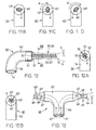
- FIG. 4 shows the section of the eye 15 according to the line IV-IV drawn in FIG. 3 with the two scleral flaps 10 and 12 swung open in the direction of the arrow 16 (FIG. 3) and arrow 16 '(FIG. 4) in section.
- the two scleral flaps 10 and 12 are held in this position for further engagement by means not shown.
- the depth of cut and the thickness 12 'of the second scleral flap 12 shown in cross section in FIG. 4 is selected, for example, in such a way that Schlemm's canal 5 is exposed in an easily accessible manner. This is essentially also achieved in that, owing to the selected depth of cut, a portion 5 'of Schlemm's canal 5 is still present on the inside 12 "of the second scleral flap 12.
- this is in the form of an over the entire width of the second Scleral flap 12 extends approximately groove-shaped Section 5 'of Schlemm's canal 5 shown.
- the two recesses 11 and 13 with the side wall 11 'and the contact surface 14 can also be seen in FIGS. 3 and 4.
- a suitable medium preferably a highly viscous sodium hyaluronate solution (high viscosity hyaluronate) injected.
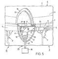
- the section of the eye 15 according to FIG. 3 is larger Scale shown and you can see a section of the Sclera 3 and the two swung open in the direction of cornea 4 or scleral flaps 10 and 12, the second recess 13 with the lateral contact surface 14 of the sclera 3 and the exposed section 18 of the Schlemm's canal 5.
- a first injection unit 25 shown which with an on an arcuate Connection part 30 arranged first probe 35 in the exposed opening 17 of Schlemm's canal 5 is introduced is.
- the injection unit 25 shown in Figure 5 is above a connected supply line 28 with a schematic shown pressure source 26 in the form of a single-chamber syringe or the like in connection.
- a schematic shown pressure source 26 in the form of a single-chamber syringe or the like in connection.
- pressure source 26 By means of, for example manually or electrically operated pressure source 26 is the medium to be injected according to arrow direction 27 in pressed the lumen of Schlemm's canal 5 and this accordingly stretched.
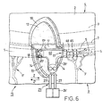
- the part of the eye 15 according to FIG. 5 is shown in FIG. 6 and the part of the sclera 3 and the two scleral flaps 10 and 12 which are swung open or up in the direction of the cornea 4, the second recess 13 with the lateral contact surface 14 of the sclera can be seen 3 and the exposed section 18 of Schlemm's canal 5. Furthermore, one can see a second injection unit inserted into the exposed Schlemm's canal 5 and designated 25 'in its entirety.
- a T- shaped connecting part 60 which is provided with two opposite probes 65 and 65 ', is arranged on the feed line 28' of the schematically illustrated injection unit 25 '.
- the one probe 65 for injecting the highly viscous sodium hyaluronate solution is inserted into an opening 17 of the Schlemm's canal 5 exposed in the region of the section 18.
- the T- shaped connecting part 60 with the probe 65 can be pulled out of the Schlemm's canal 5 and, with a slight lateral movement in the direction of arrow Z ', with the opposite probe 65' into the other opening 17 'of the Schlemm's canal 5 to inject the medium and expand the lumen.
- the medium is pressed one after the other into one opening 17 and then into the other opening 17 '.
- the injection unit 25 'shown in FIG. 6 protrudes a supply line 28 'connected to the pressure source 26 'in connection.
- manually or electrically actuated pressure source 26 ' is the one to be injected Medium according to arrow direction 27 'into the lumen of the Schlemm's canal 5 pressed.
- the one shown in Fig.6 Pressure source 26 ' is preferred in a manner not shown designed as a two-chamber syringe.
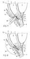
- the aqueous humor can thus in addition to the natural drainage through the trabecular tissue 8 according to arrow direction 1 'also largely over the transparent and partially permeable Descemet membrane 6 according to arrow direction 1 "(Fig.8 and Fig.9) and through the slit-shaped passage 21 into the Schlemmschen Channel 5 related recess 13 derived become.
- the second scleral flap 12 designed accordingly flat recess 13 essentially forms Reservoir for the aqueous humor, which from this is derived in Schlemm's canal 5.
- the second scleral flap 12 is preferred except for a remaining section 12.1 (Fig. 8 and Fig.9), in a manner not shown by means of a suitable surgical cutting instrument. It exists however, the possibility that first the second Scleral flap separated and then by means of the counter the Schwalbesche line pressed swabs 20 the Descemet membrane 6 from the inside of the section 4 'of the cornea 4 to form the gap-shaped passage 21 is solved.
- the columnar shape is maintained Passage 21 of the first scleral flap 10 according to the direction of the arrow 16 "(Fig.8) folded down and schematically as in Fig.9 shown on the parabolic support surface 14 placed.
- the first scleral flap 10 is then in partially known, not shown in more detail the sclera 3 is sewn.
- Room 13 '(subscleral space) in the form of the flat recess 13 is preferably still before complete sewing by means of a syringe, not shown, with highly viscous Medium (viscosity sodium hyaluronate) filled. This will prevents the folded-down first scleral flap 10 with the inside 10 "with the inside surface 13" of the recess 13 comes into contact (Fig. 9).
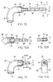
- the first embodiment is arcuate trained and with a first leg 36 and a second leg 36 'provided connector 30 in view and partially shown in section.
- the connector 30 has an inlet opening 31, which in one in the second Leg 36 'provided and delimited by a wall 32 Interior 31 'opens.
- On the second leg 36 'of the connection part 30 a tubular probe 35 is arranged, which is oriented in the axial direction and with the Interior 31 'of the arcuate connector 30 in connection standing hole 33 penetrated in the form of an outlet channel becomes.
- the probe 35 is at one end for insertion into the Schlemm's canal 5, for example, with a convex End face 34 provided. At the other end is probe 35 by means of a conical in the direction of the second leg 36 ' or transition 37 which is designed to widen in a circular arc molded on the connector 30.
- the conical or circular arc Transition 37 ensures when inserted into the opening 17, 17 'of Schlemm's canal 5 (FIG. 5) is a sealing one Facility so that the injected medium escapes any backlog in the lumen of Schlemm's canal 5 largely is prevented.
- Fig.10 In the first embodiment shown in Fig.10 is the one arranged or molded on the connecting part 30 Probe 35 designed as an elongated and flexible tube.
- the probe 35 which is designed as a flexible tube, is as shown schematically in Fig.10, with respect to the Longitudinal axis X in a spatial area with regard to its The position and orientation are freely movable.
- the probe 35 can be used for the exit of Schlemm's canal 5 (Fig.5) medium to be injected additionally with a number Outlet openings arranged at a distance from one another in the axial direction 38 be provided, which with the as an outlet channel trained bore 33 are connected.
- the probe 35 starts from the distal end or the end face 34 in the direction of the transition 37 is designed to expand conically.
- the tube can become loose due to the flexibility of insertion in Schlemm's canal 5 (Fig. 6) in terms of location and orientation to the respective inner shape of the Adjust Schlemm's canal 5 automatically.
- the probe 35 is preferably from a flexible tube, for example made of a transparent, flexible plastic tube.
- the probe 35 can also consist of a flexible Metal tubes are made of, for example is made of a nickel-titanium alloy. With the above Examples mentioned are the tubes with such limited Flexibility made that a kink at one longer embodiment of the probe is excluded.
- Fig.10A is a first variant of the on the second leg 36 'of the connecting part 30' arranged probe 35 '.
- the tubular probe 35 ' in a correspondingly designed recess 36 "of the connecting part 30 'inserted and by suitable means, for example by an adhesive connection with the connecting part 30 'firmly connected.
- the tubular probe 35 ' stands over an axially oriented and as an outlet channel trained bore 33 'with the interior 31' in Connection.
- the probe 35 ' for the exit of the medium to be injected into Schlemm's canal 5 (Fig. 5) with a number in the axial direction at a distance from each other arranged outlet openings 38 'provided with the Bore 33 'communicate.
- the related to the outside diameter of the probe 35 'offset annular end face 37' of the connecting part 30 'ensures when inserted into the Schlemmschen Channel 5 (Fig.5) also a largely sealing Contact the opening 17 and 17 'so that the escape of the injected medium in the event of a backlog in the lumen of the Schlemm's channel 5 is also prevented.
- 10B is a second variant of the one with the bore 33 " and the outlet openings 38 'and not at one shown connector arranged and tubular trained probe 35 "shown.
- this variant the distal end face 34 "of the probe 35" as a circular bead 39 trained.
- the arcuate trained connecting part 40 comprises a first leg 46 and a second leg 46 'and is essentially analogous to that described above in connection with Fig.10 Connection part 30 formed. Deviating from that is on the second leg 46 'a relatively short and with a longitudinal axis X-shaped probe 45 or 45 ', which is formed by a oriented in the axial direction and with the interior 41 'of the connecting part 40 communicating bore 43 is penetrated in the form of an outlet channel. Probe 45 can continue with a number in the axial direction at a distance to each other arranged outlet openings 48 be, which are connected to the bore 43. To the The probe 45 is, for example, inserted into Schlemm's canal 5 provided with a cambered end face 44.
- the probe 40 is in the direction of one of the second leg 46 'conical or arcuate widening transition 47 on the connecting part 40 molded.
- the conical or circular transition 47 ensures when inserted into the opening 17, 17 'of the Schlemm's canal 5 (Fig.5) a sealing system, see above that any escape of the injected medium Backflow in the lumen of Schlemm's canal 5 largely prevented becomes.
- the probe 45 starts from the distal end or the end face 44 in the direction of the transition 47 is designed to widen conically.
- the one provided in the second leg 46 'of the connecting part 40 Interior 41 ' has a funnel-shaped inner wall 42, starting from the inside diameter of the interior 41 ' in the direction of the bore 43 designed as an outlet channel is tapered.
- the towards the hole 43 essentially tapered nozzle-shaped Inner wall 42 advantageously results in a compressed one and pressure accelerated exit of the in the lumen of the Schlemm's channel 5 medium to be injected.
- the second Connecting part 40 arranged probe 45 or 45 'in a not shown This is also analogous to probe 35 'according to FIG. 10A or analogously to the probe 35 "according to FIG. 10B can.
- 11A shows this along the line XI-XI in section Connection part 40 shown with the first leg 46 and the circular cross section and provided with the bore 43 formed as an outlet channel Probe 45.
- Fig.llB is a first variant of the along the line XI-XI shown in section and molded on the connector 40 Probe 45 'shown.
- the probe 45 ' is here as an approximately elliptical in cross-section Tubes formed, which of one as an outlet channel elliptical bore 43 'is penetrated.
- 11c is the probe which is elliptical in profile cross section 45 'for better handling and better insertion into the Schlemm's channel 5 (5) with respect to the longitudinal axis X below right angle ⁇ and in Fig.llD at obtuse angle ⁇ ' the second leg 46 'of the connecting part 40 respectively molded.
- the arcuate trained connecting part 50 comprises a first leg 56 and a second leg 56 'and is essentially analogous to that in connection with that in Fig. 10 or Fig.10A or Fig.10B described connector 30 or with the aid of FIGS. 11 or 11A to 11D described connector 40 formed.
- an elongated probe 55, 55 ' is formed on the second leg 56', which are circular or elliptical in profile cross-section is.
- the probe 55, 55 ' is different from the embodiment according to Fig. 10 and Fig. 11 on the outer circumference at least one oriented in the axial direction thereof and profile groove 53 or 53 'designed as an outlet channel Mistake.
- the individual profile groove 53 or 53 ' stands with interior 51 'of the second leg delimited by the wall 52 56 'in connection.
- the probe is 55 or 55 ' analogous to the probes 35 and 45 described above on the End face 54 is, for example, cambered.
- the probe 50 is in the direction of one of the second leg 56 'conical or arcuate widening transition 57 on the connector 50 molded.
- the conical or circular transition 57 ensures when inserted into the opening 17, 17 'of the Schlemm's canal 5 (Fig.5) a sealing system, see above that any escape of the injected medium Backflow in the lumen of Schlemm's canal 5 largely prevented becomes.
- the probe 55 or 55 ′ arranged on the connecting part 50 according to FIG Fig.12 can also be analogous to that in connection above described with Fig.10 and on the arcuate connector 30 arranged probe 35 made of a flexible Plastic tubes made with limited flexibility become.
- the probe 55, 55 ' is in relation to the longitudinal axis X in a spatial area in terms of their location and orientation analogous to Fig. 10 designed to move freely.
- FIGS. 12A and 12B each show the connecting part 50 with the average along the line XII-XII shown probe 55 and 55 '.
- connector 50 is the probe 55 in Profile cross-section circular.
- the probe 55 On the outside the probe 55, for example, several are distributed to each other and in connection with the interior 51 'of the connecting part 50 standing and each designed as an outlet channel 53 arranged.
- the connection part shown in FIG. 12B 50 is the integrally formed probe 55 'in the profile cross section elliptical.
- the elliptical Probe 55 ' are also several distributed to each other and in connection with the interior 51 'of the connecting part 50 standing profile grooves 53 'arranged.
- connection parts 30, 40 or 50 each with it arranged or molded probes 35,45,45 ' or 55,55 'are designed such that the medium is sequential either in one or the other opposite Opening or into the lumen of the surgically exposed Schlemm's canal 5 is injectable (Fig. 6).
- FIG. 13 shows, as a third exemplary embodiment, the connection part 60 shown in view for the injection unit 25 ′ shown schematically in FIG. 6.
- the connection part 60 which is approximately T- shaped in profile cross section, has on the upper section 66 'two probes 65 and 65' arranged opposite one another and each penetrated by a bore 63 or 63 'designed as an outlet channel. Furthermore, a leg 66, which is arranged transversely thereto and is provided with two separate inlet openings 61, 61 ', is formed on the upper section 66'.
- the inlet openings 61 and 61 ' are connected to the holes 63 and 63' provided in the probes 65 and 65 '.
- the length of the two probes 65 and 65 ' can also be different, as shown schematically in FIG.
- probes 65 and 65 'can be analogous to probe 35 (Fig. 10) each be designed as a flexible tube, which when inserted into the opening of Schlemm's canal 5 with respect to the longitudinal axis X with respect to the position and Orientation is free to move and adhere to the shape of the lumen.
- the two probes 65 and 65 'can also in profile cross-section according to the variant according to Fig.llA and 11B or according to the variant according to FIG. 12A and 12B are formed.
- the probe 65 or 65 ' is, for example, cambered on the end face 64 and 64', analogously to the probes 35 and 45 described above.
- the two probes 65 and 65 ' are each integrally formed on the T- shaped connecting part 60 by means of a transition 67 and 67' which widens conically or in the shape of a circular arc in the direction of the upper section 66 '.
- the conical or circular-shaped transition 67 and 67 ' ensures a sealing system each time it is inserted into the opening 17, 17' of Schlemm's canal 5 (FIG. 5), so that the injected medium escapes largely in the event of a backflow in the lumen of Schlemm's canal 5 is prevented.
Abstract
Description
Die Erfindung bezieht sich auf ein Verfahren zum Verbessern des Kammerwasserabflusses in einem Auge sowie auf eine Vorrichtung zum Aufweiten des zirkulären Schlemmschen Kanals.The invention relates to a method for improvement of the aqueous humor outflow in one eye and on a device to widen the circular Schlemm's canal.
Aus den Druckschriften (US-A 5,360,399 und US-A 5,486,165) ist ein Verfahren sowie eine Vorrichtung zur Durchführung des Verfahrens bekannt, mittels welchem/welcher das dem Schlemmschen Kanal vorgelagerte und infolge krankhafter Veränderungen den Abfluss des Kammerwassers teilweise oder vollständig obstruierende Trabekulargewebe mittels einer in den Schlemmschen Kanal injizierten hochviskosen, wässrigen Lösung im wesentlichen hydraulisch gedehnt wird, und dadurch an einigen Stellen für den Abfluss des Kammerwassers geöffnet wird.From the publications (US-A 5,360,399 and US-A 5,486,165) is a method and an apparatus for performing the Method known, by means of which the Schlemmschen Channel upstream and as a result of pathological changes the drainage of the aqueous humor partially or completely Obstructing trabecular tissue using one in the Schlemmschen Channel injected highly viscous, aqueous solution essentially is hydraulically stretched, and thereby on some Places for the drainage of the aqueous humor is opened.
Der Erfindung liegt die Aufgabe zugrunde ein Verfahren anzugeben sowie eine Vorrichtung zu schaffen, mittels welchem/welcher der erforderliche Abfluss des Kammerwassers über das natürliche Kanalsystem in einem Auge und infolge dessen eine den Druck regulierende Zirkulation des Kammerwassers verbessert wird.The invention has for its object to provide a method and to create a device by means of which the required outflow of the aqueous humor over the natural canal system in one eye and as a result a pressure regulating circulation of the aqueous humor is improved.
Die Aufgabe hinsichtlich des Verfahrens ist gekennzeichnet durch einen ersten lamellaren Einschnitt an der Oberfläche der Sklera mit in Richtung der Kornea aufgeschwenktem ersten Skleralappen und analog ausgebildeter erster Ausnehmung, einen innerhalb der ersten Ausnehmung angeordneten zweiten lamellaren Einschnitt mit in Richtung des ersten Skleralappens aufgeschwenktem zweiten Skleralappen und analog ausgebildeter zweiter Ausnehmung sowie ein im Bereich der zweiten Ausnehmung freigelegtes Teilstück des Schlemmschen Kanals mit zwei gegenüberliegenden Öffnungen zum Injizieren eines den Schlemmschen Kanal dehnenden Mediums, wobei der erste Skleralappen nach dem Abtrennen des zweiten Skleralappens auf eine analog dem zweiten Einschnitt ausgebildete Auflagefläche gelegt wird und der dadurch gebildete subsklerale Raum vor dem vollständigen Verschliessen mit einem viskosen Medium gefüllt wird.The task regarding the procedure is marked through a first lamellar incision on the surface the sclera with the first swung open in the direction of the cornea Scleral lobes and analogous first recess, one second lamellar arranged within the first recess Incision in the direction of the first scleral flap swung open second scleral flap and similarly trained second recess and one in the area of the second recess exposed section of Schlemm's canal with two opposite openings for injecting a Schlemm's canal-stretching medium, being the first scleral lobe after cutting off the second scleral flap to one analogous to the second incision formed support surface and the sub-scleral space thus formed completely sealed with a viscous medium becomes.
Nach einem weiteren Merkmal des Verfahrens besteht zudem die Möglichkeit, dass zur Bildung eines die kammerwasserdurchlässige Descemet-Membran mit der zweiten Ausnehmung beziehungsweise mit dem subskleralen Raum verbindenden Spalts die Descemet-Membrane durch eine geringe Anpresskraft im Bereich der Schwalbeschen Linie von der Kornea gelöst wird.According to a further feature of the method, there is also Possibility to form a water permeable Descemet membrane with the second recess respectively with the gap connecting the sub-scleral space Descemet membrane due to a low contact pressure in the area the Schwalbesch line is detached from the cornea.
Hierdurch wird erreicht, dass das in natürlicherweise über das Trabekulargewebe in den Schlemmschen Kanal abgeleitete Kammerwasser zusätzlich noch von der Vorderkammer über die Descemt-Membran und den Spalt in den mit dem Schlemmschen Kanal in Verbindung stehenden subskleralen Raum gelangen kann.This ensures that the naturally over the trabecular tissue was derived into Schlemm's canal Aqueous humor in addition from the anterior chamber over the Descemt membrane and the gap in the Schlemm's canal related sub-scleral space.
Die Vorrichtung ist gekennzeichnet durch eine in den Schlemmschen Kanal einführbare und für das zu injizierende Medium mit mindestens einem Austrittskanal versehene Sonde, welche eine in axialer Richtung orientierte und mindestens dem zweifachen Durchmesser entsprechende Länge aufweist.The device is characterized by one in the Schlemmschen Channel insertable and for the medium to be injected with at least one outlet channel provided, which one oriented in the axial direction and at least twice Has diameter corresponding length.
Weitere Vorteile, Merkmale und Einzelheiten der Erfindung ergeben sich aus den einzelnen Patentansprüchen, der nachstehenden Beschreibung und der Zeichnung.Further advantages, features and details of the invention result from the individual claims, the following Description and the drawing.
Die Erfindung wird nachstehend anhand von Ausführungsbeispielen in Verbindung mit der Zeichnung beschrieben. Es zeigt:
- Fig.1
- ein in schematischer Ansicht und in grösserem Massstab dargestelltes Teilstück eines Auges mit einem ersten parabolischen Einschnitt in der Sklera und aufgeklapptem ersten Skleralappen;
- Fig.2
- das entlang der Linie II-II in Fig.1 im Schnitt dargestellte Teilstück des Auges mit aufgeklapptem ersten Skleralappen;
- Fig.3
- das Teilstück des Auges gemäss Fig.1 mit einem innerhalb des ersten parabolischen Einschnitts angeordneten zweiten parabolischen Einschnitt und aufgeklapptem zweiten Skleralappen;
- Fig.4
- das entlang der Linie IV-IV in Fig.3 im Schnitt dargestellte Teilstück des Auges mit den beiden aufgeklappten Skleralappen;
- Fig.5
- ein erstes Ausführungsbeispiel einer in den freigelegten Schlemmschen Kanal eingeführten und an einem bogenförmigen Anschlussteil angeordneten Sonde;
- Fig.6
- ein zweites Ausführungsbeispiel der in den freigelegten Schlemmschen Kanal eingeführten und an einem T-förmigen Anschlussteil angeordneten Sonde;
- Fig.7
- das Teilstück des Auges gemäss Fig.4 mit einem im Bereich der beiden aufgeklappten Skleralappen mit geringer Kraft im wesentlichen gegen die Schwalbesche Linie wirkenden Tupfer;
- Fig. 8
- das Teilstück des Auges gemäss Fig.7 bei welchem die Descemets-Membran von der Kornea gelöst und der zweite Skleralappen abgetrennt ist;
- Fig.9
- das Teilstück des Auges gemäss Fig.8 mit heruntergeklapptem ersten Skleralappen;
- Fig.10
- ein in Ansicht sowie in grösserem Massstab dargestelltes erstes Ausführungsbeispiel der an einem Anschlussteil angeformten Sonde;
- Fig.10A
- eine erste Variante der an dem Anschlussteil gemäss Fig.10 angeordneten Sonde;
- Fig.10B
- eine zweite Variante der an dem Anschlussteil gemäss Fig.10 angeordneten Sonde;
- Fig.11
- ein in Ansicht und teilweise im Schnitt dargestelltes zweites Ausführungsbeispiel der an einem Anschlussteil angeformten Sonde;
- Fig.11A
- das entlang der Linie XI-XI im Schnitt dargestellte Anschlussteil gemäss Fig.11 mit der im Profilquerschnitt dargestellten Sonde;
- Fig.11B
- das Anschlussteil gemäss Fig.11 mit einer ersten Variante der angeformten Sonde;
- Fig.11C
- eine im Profilquerschnitt dargestellte zweite Variante der Sonde gemäss Fig.11B;
- Fig.11D
- eine im Profilquerschnitt dargestellte dritte Variante der Sonde gemäss Fig.11B;
- Fig.12
- ein in Ansicht und teilweise im Schnitt dargestelltes drittes Ausführungsbeispiel der an einem bogenförmigen Anschlussteil angeformten Sonde;
- Fig.12A
- das entlang der Linie XII-XII im Schnitt dargestellte Anschlussteil gemäss Fig.12 mit der im Profilquerschnitt dargestellten Sonde;
- Fig.12B
- eine im Profilquerschnitt dargestellten Variante der Sonde gemäss Fig.12A; und
- Fig.13
- das T-förmige Anschlussteil der Injektionseinheit gemäss Fig.6 mit zwei gegenüberliegend angeformten Sonden.
- Fig. 1
- a part of an eye shown in a schematic view and on a larger scale with a first parabolic incision in the sclera and opened first scleral flap;
- Fig. 2
- the section of the eye shown in section along the line II-II in FIG. 1 with the first scleral flap opened;
- Fig. 3
- the section of the eye according to FIG. 1 with a second parabolic incision arranged within the first parabolic incision and an opened second scleral flap;
- Fig. 4
- the section of the eye shown in section along the line IV-IV in FIG. 3 with the two opened scleral flaps;
- Fig. 5
- a first embodiment of a probe inserted into the exposed Schlemm's canal and arranged on an arcuate connector;
- Fig. 6
- a second embodiment of the probe inserted into the exposed Schlemm's canal and arranged on a T-shaped connector;
- Fig. 7
- the section of the eye according to FIG. 4 with a swab acting in the region of the two opened scleral flaps with little force essentially against the Schwalbesche line;
- Fig. 8
- the section of the eye according to FIG. 7 in which the Descemets membrane is detached from the cornea and the second scleral flap is separated;
- Fig. 9
- the section of the eye according to FIG. 8 with the first scleral flap folded down;
- Fig. 10
- a first embodiment shown in view and on a larger scale of the probe formed on a connecting part;
- Fig.10A
- a first variant of the probe arranged on the connecting part according to FIG. 10;
- Fig. 10B
- a second variant of the probe arranged on the connecting part according to FIG. 10;
- Fig. 11
- a second embodiment shown in view and partially in section of the probe formed on a connecting part;
- Fig.11A
- the connecting part shown in section along the line XI-XI according to FIG. 11 with the probe shown in the profile cross section;
- Fig. 11B
- the connector according to Figure 11 with a first variant of the molded probe;
- Fig.11C
- a second variant of the probe shown in profile cross-section according to Fig. 11B;
- Fig.11D
- a third variant of the probe shown in profile cross section according to FIG. 11B;
- Fig. 12
- a third embodiment shown in view and partly in section of the probe formed on an arcuate connector;
- Fig.12A
- the connection part shown along the line XII-XII in accordance with FIG. 12 with the probe shown in the profile cross section;
- Fig.12B
- a variant of the probe shown in profile cross section according to Fig.12A; and
- Fig. 13
- the T-shaped connecting part of the injection unit according to FIG. 6 with two probes molded onto it.
Fig.1 zeigt ein in grösserem Massstab sowie in schematischer
Ansicht dargestelltes Teilstück eines Auges 15 und man erkennt
jeweils ein Teilstück der Regenbogenhaut 2 (Iris), der
Hornhaut 4 (Kornea), der Lederhaut 3 (Sklera), ein Teilstück
des zirkulären Schlemmschen Kanals 5 (Sinus venosus sclera)
und das aus einer Vielzahl von Kanälen gebildete Kanalsystem
3' für das Kammerwasser. Weiterhin erkennt man in Fig.1 einen
ersten etwa parabolisch ausgebildeten Einschnitt (Inzision)
in der Sklera 3, einen analog dem Einschnitt ausgebildeten
und in Richtung der Kornea 4 aufgeschwenkten Skleralappen 10
sowie eine analog demselben ausgebildete erste Ausnehmung 11
mit einer umlaufenden Seitenwand 11'. Der Skleralappen 10
wird durch nicht dargestellte Mittel in der aufgeschwenkten
Position gehalten.Fig. 1 shows a larger scale and in a schematic
View shown section of an
In Fig.2 ist das Teilstück des Auges 15 gemäss der in Fig.1
eingezeichneten Linie II-II im Schnitt sowie in grösserem
Massstab dargestellt und man erkennt ein Teilstück der Sklera
3, ein Teilstück der Kornea 4 mit der Descemet-Membrane 6
(Descemet's Membran) und der Schwalbeschen Linie 7 (Schwalbe's
line), ein Teilstück der Regenbogenhaut 2 sowie ein
Teilstück der mittels der Zonularfasern 9' mit der Lederhaut
3 verbundenen Linse 9. Weiterhin erkennt man den gemäss
Pfeilrichtung 16 aufgeschwenkten ersten Skleralappen 10 mit
der analog ausgebildeten ersten Ausnehmung 11 sowie den
Schlemmschen Kanal 5 mit dem vorgelagerten Trabekulargewebe 8
(trabecular meshwork).2 shows the section of the
In Fig.2 ist mit den Pfeilen 1 im wesentlichen die Zirkulation
des Kammerwassers (humor aquosus) und mit den Pfeilen 1'
der natürliche Abfluss dargestellt. Bei einem gesunden Auge
zirkuliert das sich ständig erneuernde Kammerwasser gemäss
Pfeilrichtung 1 von der Hinterkammer H zur Vorderkammer V und
wird im Kammerwinkel V' (angulus irido-cornealis) gemäss der
Pfeile 1' über das Trabekulargewebe 8 in den Schlemmschen Kanal
5 und von dort über das Kanalsystem 3' (Fig.1) in das
nicht dargestellte natürliche Venensystem abgeleitet. Bei einem
infolge Verstopfung oder dergleichen nur teilweise funktionsfähigen
beziehungsweise funktionsunfähigen Trabekulargewebe
8 kann der natürliche Abfluss des Kammerwassers derart
begrenzt werden, dass der Druck im Inneren des Auges 15 ansteigt
und infolge dessen die Durchblutung und somit die
Funktion der Sehnerven (nicht dargestellt) eingeschränkt
wird. Diese Krankheit ist allgemein unter dem Begriff "Glaukom"
bekannt, welche zur Erblindung des betroffenen Auges
führen kann.In Fig.2 the
Für den mikrochirurgischen Eingriff wird zunächst die nicht
dargestellte Bindehaut des Auges mit geeigneten Mitteln zurückgezogen
und dadurch ein ausreichendes Teilstück der Sklera
3 für den ersten parabolförmigen Einschnitt (Inzision)
freigelegt. Nach dem ersten Einschnitt wird der dem Einschnitt
entsprechend ausgebildete erste Skleralappen 10 in
Richtung der Kornea 4 geklappt und infolge dessen die erste
Ausnehmung 11 mit der umlaufenden Seitenwand 11' freigelegt.
Die Tiefe des ersten beispielsweise 3mm x 3mm grossen Einschnitts
ist beispielsweise so gewählt, dass die Dicke 10'
des in Fig.2 im Profilquerschnitt dargestellten ersten Skleralappens
10 etwa 1/3 der in diesem Bereich natürlichen Dicke
der Sklera 3 entspricht. Der Schlemmsche Kanal 5 ist in dieser
ersten Phase (Fig.2) noch nicht freigelegt.For the microsurgical intervention, that is not initially
shown conjunctiva of the eye withdrawn with suitable means
and thereby a sufficient section of the
Fig.3 zeigt das Teilstück des Auges 15 mit einem innerhalb
des ersten parabolischen Einschnitts angeordneten zweiten
Einschnitt. Nach der Durchführung des zweiten Einschnitts
wird ein entsprechend parabolförmig ausgebildeter zweiter
Skleralappen 12 in Richtung der Kornea 4 aufgeklappt, infolge
dessen eine analog des zweiten Skleralappens 12 ausgebildete
zweite Ausnehmung 13 freigelegt wird. Die Tiefe des zweiten
Einschnitts ist so gewählt, dass in dieser Phase der Schlemmsche
Kanal 5 bei aufgeschwenktem zweiten Skleralappen 12 über
die gesamte Breite des mit 18 bezeichneten Teilstücks der
Ausnehmung 13 freigelegt ist. In dieser Phase sind die beiden
im Bereich des Teilstücks 18 gegenüberliegend zueinander angeordneten
Öffnungen 17 und 17' des Schlemmschen Kanals 5 zum
Einführen einer entsprechend ausgebildeten Sonde (Fig.5 und
Fig.6) zugänglich.3 shows the section of the
In Fig.4 ist das Teilstück des Auges 15 gemäss der in Fig.3
eingezeichneten Linie IV-IV mit den beiden gemäss Pfeilrichtung
16 (Fig.3) und Pfeilrichtung 16' (Fig.4) aufgeschwenkten
Skleralappen 10 und 12 im Schnitt dargestellt. Die beiden
Skleralappen 10 und 12 sind für den weiteren Eingriff mit
nicht dargestellten Mitteln in dieser Position gehalten. Die
Schnitttiefe sowie die davon abhängige Dicke 12' des in Fig.4
im Profilquerschnitt dargestellten zweiten Skleralappens 12
ist beispielsweise so gewählt, dass der Schlemmsche Kanal 5
gut zugänglich freigelegt ist. Dies wird im wesentlichen auch
dadurch erreicht, dass infolge der gewählten Schnitttiefe an
der Innenseite 12" des zweiten Skleralappens 12 noch ein
Teilstück 5' des Schlemmschen Kanals 5 vorhanden ist. In
Fig.3 ist das in Form einer sich über die gesamte Breite des
zweiten Skleralappens 12 erstreckende etwa rillenförmige
Teilstück 5' des Schlemmschen Kanals 5 dargestellt. Weiterhin
erkennt man in Fig.3 und Fig.4 die beiden Ausnehmungen 11 und
13 mit der Seitenwand 11' und der Auflagefläche 14.4 shows the section of the
Section 5 'of Schlemm's
In einer dritten Phase wird mittels einer entsprechend ausgebildeten
Injektionseinheit 25 oder 25' gemäss Fig.5 oder
Fig.6 in die beiden seitlichen Öffnungen 17 und 17' des freigelegten
Schlemmschen Kanals 5 ein geeignetes Medium, vorzugsweise
eine hochviscose Natrium-Hyaluronat-Lösung (high
viscosity hyaluronate) injiziert. Hierdurch wird das Lumen
des Schlemmschen Kanals 5 mindestens über die gesamte Länge
der eingeführten Sonde aufgeweitet.In a third phase, there is a correspondingly trained
In Fig.5 ist das Teilstück des Auges 15 gemäss Fig.3 in grösserem
Massstab dargestellt und man erkennt ein Teilstück der
Sklera 3 sowie die beiden in Richtung der Kornea 4 aufgeschwenkten
beziehungsweise hochgeklappten Skleralappen 10 und
12, die zweite Ausnehmung 13 mit der seitlichen Auflagefläche
14 der Sklera 3 sowie das freigelegte Teilstück 18 des
Schlemmschen Kanals 5. Zum Injizieren der hochviscosen Natrium-Hyaluronat-Lösung
ist in Fig.5 weiterhin eine erste Injektionseinheit
25 dargestellt, welche mit einer an einem bogenförmigen
Anschlussteil 30 angeordneten ersten Sonde 35 in die
freigelegte Öffnung 17 des Schlemmschen Kanals 5 eingeführt
ist. Nach dem Aufweiten des Lumens mittels der injizierten
Natrium-Hyaluronat-Lösung auf der einen Seite wird die Injektionseinheit
25 mit der Sonde 35 aus der Öffnung 17 herausgezogen
und in nicht näher dargestellter Weise entsprechend gedreht
in die andere, gegenüberliegende Öffnung 17' des
Schlemmschen Kanals 5 zum Injizieren des Mediums beziehungsweise
zum Aufweiten des Lumens eingeführt. In FIG. 5, the section of the
Die in Fig.5 dargestellte Injektionseinheit 25 steht über eine
daran angeschlossene Zuführleitung 28 mit einer schematisch
dargestellten Druckquelle 26 in Form einer Einkammer-Spritze
oder dergleichen in Verbindung. Mittels der beispielsweise
manuell oder elektrisch betätigbaren Druckquelle
26 wird das zu injizierende Medium gemäss Pfeilrichtung 27 in
das Lumen des Schlemmschen Kanals 5 gepresst und dieser entsprechend
gedehnt.The
Einzelheiten und weitere zweckmässige Ausgestaltungen der jeweils
mit der ersten Zuführleitung 28 in Verbindung stehenden
Anschlussteile 30,40 und 50 sowie die daran angeformten beziehungsweise
angeordneten Sonden 35,45 und 55 sowie weitere
Ausgestaltungen derselben werden nachstehend in Verbindung
mit den Figuren 10, 10A, 10B und 11, 11A bis 11D sowie 12, 12A,
12B und 13 im einzelnen beschrieben.Details and further expedient configurations of each
connected to the
In Fig.6 ist das Teilstück des Auges 15 gemäss Fig.5 dargestellt
und man erkennt das Teilstück der Sklera 3 sowie die
beiden in Richtung der Kornea 4 aufgeschwenkten oder hochgeklappten
Skleralappen 10 und 12, die zweite Ausnehmung 13 mit
der seitlichen Auflagefläche 14 der Sklera 3 sowie das freigelegte
Teilstück 18 des Schlemmschen Kanals 5. Weiterhin erkennt
man eine in den freigelegten Schlemmschen Kanal 5 eingeführte
und in der Gesamtheit mit 25' bezeichnete zweite Injektionseinheit.
Bei diesem Ausführungsbeispiel ist an die
Zuführleitung 28' der schematisch dargestellten Injektionseinheit
25' ein T-förmig ausgebildetes und mit zwei gegenüberliegenden
Sonden 65 und 65' versehenes Anschlussteil 60
angeordnet.The part of the
Bei dem in Fig.6 dargestellten Ausführungsbeispiel besteht
die Möglichkeit, dass in einer ersten Phase die eine Sonde 65
zum Injizieren der hochviscosen Natrium-Hyaluronat-Lösung in
die eine im Bereich des Teilstücks 18 freigelegte Öffnung 17
des Schlemmschen Kanals 5 eingeführt wird. Nach dem Aufweiten
des Schlemmschen Kanals 5 kann das T-förmige Anschlussteil 60
mit der Sonde 65 aus dem Schlemmschen Kanal 5 herausgezogen
und durch eine geringe seitliche Bewegung in Pfeilrichtung Z'
mit der gegenüberliegenden Sonde 65' in die andere Öffnung
17' des Schlemmschen Kanals 5 zum Injizieren des Mediums und
Aufweiten des Lumens eingeführt werden. Bei dieser Variante
wird das Medium nacheinander in die eine Öffnung 17 und anschliessend
in die andere Öffnung 17' eingepresst.In the exemplary embodiment shown in FIG. 6, there is the possibility that in a first phase the one
Bei einer nicht dargestellten Variante besteht jedoch auch
die Möglichkeit, dass das T-förmige Anschlussteil 60 im Bereich
des freigelegten Teilstücks 18 zuerst mit der einen
Sonde 65 in die eine Öffnung 17 und gleichzeitig durch eine
geringe seitliche Verschiebung gemäss Pfeilrichtung Z' mit
der zweiten Sonde 65' in die andere gegenüberliegende Öffnung
17' eingeführt wird. Bei dieser Variante besteht folglich die
Möglichkeit, dass das Medium mittels der Druckquelle 26'
gleichzeitig in die beiden Öffnungen 17 und 17' des freigelegten
Schlemmschen Kanals 5 eingepresst werden kann.In a variant not shown, however, there is also the possibility that the T- shaped connecting
Die in Fig.6 dargestellte Injektionseinheit 25' steht über
eine daran angeschlossene Zuführleitung 28' mit der Druckquelle
26' in Verbindung. Mittels der beispielsweise manuell
oder elektrisch betätigbaren Druckquelle 26' wird das zu injizierende
Medium gemäss Pfeilrichtung 27' in das Lumen des
Schlemmschen Kanals 5 gepresst. Die in Fig.6 dargestellte
Druckquelle 26' ist in nicht näher dargestellter Weise vorzugsweise
als Zweikammer-Spritze ausgebildet. Hierdurch besteht
die Möglichkeit, dass das Medium entweder mit der einen
Sonde 65 oder mit der anderen gegenüberliegenden Sonde 65'
beziehungsweise gleichzeitig mit beiden Sonden 65 und 65' in
das Lumen des Schlemmschen Kanals 5 eingepresst werden kann.The injection unit 25 'shown in FIG. 6 protrudes
a supply line 28 'connected to the pressure source
26 'in connection. For example, manually
or electrically actuated pressure source 26 'is the one to be injected
Medium according to arrow direction 27 'into the lumen of the
Schlemm's
Nach dem Aufweiten des Schlemmschen Kanals 5 mittels der Injektionseinheit
25 (Fig.5) beziehungsweise der Injektionseinheit
25' (Fig.6) werden diese in nicht dargestellter Weise
wieder entfernt.After widening Schlemm's
In einer nächsten Phase wird, wie in Fig.7 dargestellt, mittels
eines Tupfers 20 oder dergleichen infolge einer geringen
Kraft mit dem Tupfer 20 im Bereich der Schwalbeschen Linie
die Descemet-Membrane 6 von der Innenseite der Kornea 4 derart
gelöst, dass zwischen der Kornea 4 und der Descemet-Membrane
6 ein in Fig.8 in grösserem Massstab und schematisch
dargestellter Durchgang 21 entsteht. Der etwa spaltförmige
Durchgang 21 erstreckt sich in nicht dargestellter Weise über
die gesamte Breite der in Fig.5 und Fig.6 in Ansicht sowie in
grösserem Massstab dargestellten zweiten Ausnehmung 13.In a next phase, as shown in Fig.7, using
a
Mit dem spaltförmig ausgebildeten Durchgang 21 wird eine zusätzliche
Verbindung zwischen der Vorderkammer V und der
zweiten Ausnehmung 13 geschaffen. Das Kammerwasser kann somit
zusätzlich zu dem natürlichen Abfluss über das Trabekulargewebe
8 gemäss Pfeilrichtung 1' auch noch über die weitgehend
transparente und für das Kammerwasser teildurchlässige Descemet-Membrane
6 gemäss Pfeilrichtung 1" (Fig.8 und Fig.9) und
durch den spaltförmigen Durchgang 21 in die mit dem Schlemmschen
Kanal 5 in Verbindung stehende Ausnehmung 13 abgeleitet
werden. Die dem zweiten Skleralappen 12 entsprechend ausgebildete
flächige Ausnehmung 13 bildet im wesentlichen ein
Sammelbecken (Reservoir) für das Kammerwasser, welches von
diesem in den Schlemmschen Kanal 5 abgeleitet wird.With the gap-shaped
In einer weiteren Phase wird der zweite Skleralappen 12, vorzugsweise
bis auf ein restliches Teilstück 12.1 (Fig.8 und
Fig.9), in nicht näher dargestellter Weise mittels eines geeigneten
chirurgischen Schneidinstruments abgetrennt. Es besteht
jedoch auch die Möglichkeit, dass zuerst der zweite
Skleralappen abgetrennt und anschliessend mittels des gegen
die Schwalbesche Linie gedrückten Tupfers 20 die Descemet-Membrane
6 von der Innenseite des Teilstücks 4' der Kornea 4
zur Bildung des spaltförmigen Durchgangs 21 gelöst wird.In a further phase, the second
In einer nächsten Phase wird unter Beibehaltung des spaltförmigen
Durchgangs 21 der erste Skleralappen 10 gemäss Pfeilrichtung
16" (Fig.8) herunter geklappt und wie in Fig.9 schematisch
dargestellt auf die parabolförmige Auflagefläche 14
gelegt. Anschliessend wird der erste Skleralappen 10 in an
sich bekannter, nicht näher dargestellter Weise teilweise mit
der Sklera 3 vernäht. Der infolge des abgetrennten zweiten
Skleralappens 12 hinter dem ersten Skleralappen 10 entstandene
Raum 13' (subscleral space) in Form der flächigen Ausnehmung
13 wird vorzugsweise vor dem vollständigen Vernähen noch
mittels einer nicht dargestellten Spritze mit hochviscosem
Medium (viscosity sodium hyaluronate) gefüllt. Hierdurch wird
verhindert, dass der heruntergeklappte erste Skleralappen 10
mit der Innenseite 10" mit der Innenfläche 13" der Ausnehmung
13 in Kontakt kommt (Fig.9).In a next phase, the columnar shape is maintained
An dieser Stelle wird darauf hingewiesen, dass ergänzend zu
den vorstehend beschriebenen Ausführungsbeispielen und Varianten
die Möglichkeit besteht, dass zur Aufrechterhaltung des
verbesserten Kammerwasserabflusses ein Stützmittel aus geeignetem
Material in den aufgeweiteten Schlemmschen Kanal 5 beziehungsweise
in den spaltförmigen Durchgang 21 und zusätzlich
in den subskleralen Raum 13' implantiert wird. Diese
Massnahme sowie das speziell ausgebildete Stützmittel sind
nicht Gegenstand vorliegener Erfindung und werden deshalb
nicht näher beschrieben.At this point it should be noted that in addition to
the exemplary embodiments and variants described above
there is a possibility that to maintain the
improved aqueous humor drainage a suitable proppant
Material in the expanded Schlemm's
In Fig.10 ist als erstes Ausführungsbeispiel das bogenförmig
ausgebildete und mit einem ersten Schenkel 36 sowie einem
zweiten Schenkel 36' versehene Anschlussteil 30 in Ansicht
und teilweise im Schnitt dargestellt. Das Anschlussteil 30
hat eine Eintrittsöffnung 31, welche in einen im zweiten
Schenkel 36' vorgesehenen und durch eine Wand 32 begrenzten
Innenraum 31' mündet. An dem zweiten Schenkel 36' des Anschlussteils
30 ist eine röhrchenförmige Sonde 35 angeordnet,
welche von einer in axialer Richtung orientierten und mit dem
Innenraum 31' des bogenförmigen Anschlussteils 30 in Verbindung
stehende Bohrung 33 in Form eines Austrittskanals durchdrungen
wird.In Fig. 10, the first embodiment is arcuate
trained and with a
Die Sonde 35 ist an dem einen Ende zum Einführen in den
Schlemmschen Kanal 5 beispielsweise mit einer bombierten
Stirnseite 34 versehen. An dem anderen Ende ist die Sonde 35
mittels eines in Richtung des zweiten Schenkels 36' konisch
oder kreisbogenförmig erweiternd ausgebildeten Übergang 37 an
dem Anschlussteil 30 angeformt. Der konische oder kreisbogenförmige
Übergang 37 gewährleistet beim Einführen in die Öffnung
17,17' des Schlemmschen Kanals 5 (Fig.5) eine abdichtende
Anlage, so dass ein Entweichen des injizierten Mediums bei
etwaigem Rückstau im Lumen des Schlemmschen Kanals 5 weitgehend
verhindert wird.The
Bei dem in Fig.10 dargestellten ersten Ausführungsbeispiel
ist die am Anschlussteil 30 angeordnete beziehungsweise angeformte
Sonde 35 als längliches und flexibles Röhrchen ausgebildet.
Die als flexibles Röhrchen ausgebildete Sonde 35 ist
wie in Fig.10 schematisch dargestellt, in Bezug auf die
Längsachse X in einem räumlichen Bereich hinsichtlich seiner
Lage und Orientierung frei beweglich ausgebildet. Die Sonde
35 kann für den Austritt des in den Schlemmschen Kanal 5
(Fig.5) zu injizierenden Mediums zusätzlich mit einer Anzahl
in axialer Richtung im Abstand zueinander angeordneten Austrittsöffnungen
38 versehen sein, welche mit der als Austrittskanal
ausgebildeten Bohrung 33 in Verbindung stehen.In the first embodiment shown in Fig.10
is the one arranged or molded on the connecting
Bei einer nicht näher dargestellten Variante besteht auch die
Möglichkeit, dass die Sonde 35 ausgehend von dem distalen Ende
beziehungsweise der Stirnseite 34 in Richtung des Übergangs
37 konisch erweiternd ausgebildet ist. In a variant, not shown, there is also
Possibility that the
Das Röhrchen kann sich aufgrund der Flexibilität beim Einführen
in den Schlemmschen Kanal 5 (Fig.6) hinsichtlich der Lage
und Orientierung an die jeweilige innere Formgebung des
Schlemmschen Kanals 5 selbsttätig anpassen. Die Sonde 35 ist
vorzugsweise aus einem flexiblen Röhrchen, beispielsweise aus
einem transparenten, flexiblen Kunststoffröhrchen hergestellt.
Weiterhin kann die Sonde 35 aber auch aus einem flexiblen
Metallröhrchen bestehen, welches beispielsweise aus
einer Nickel-Titan-Legierung hergestellt ist. Bei den vorstehend
erwähnten Beispielen sind die Röhrchen mit derart begrenzter
Flexibilität hergestellt, dass ein Abknicken bei einer
längeren Ausführungsform der Sonde ausgeschlossen ist.The tube can become loose due to the flexibility of insertion
in Schlemm's canal 5 (Fig. 6) in terms of location
and orientation to the respective inner shape of the
Adjust Schlemm's
In Fig.10A ist eine erste Variante der an dem zweiten Schenkel
36' des Anschlussteils 30' angeordneten Sonde 35' dargestellt.
Bei dieser Variante ist die röhrchenförmige Sonde 35'
in eine entsprechend ausgebildete Ausnehmung 36" des Anschlussteils
30' eingeschoben und durch geeignete Mittel,
beispielsweise durch eine Klebverbindung mit dem Anschlussteil
30' fest verbunden. Die röhrchenförmige Sonde 35'
steht über eine in axialer Richtung orientierte und als Austrittkanal
ausgebildete Bohrung 33' mit dem Innenraum 31' in
Verbindung. Weiterhin ist die Sonde 35' für den Austritt des
in den Schlemmschen Kanal 5 (Fig.5) zu injizierenden Mediums
mit einer Anzahl in axialer Richtung im Abstand zueinander
angeordneten Austrittsöffnungen 38' versehen, welche mit der
Bohrung 33' in Verbindung stehen. Bei dieser Variante ist die
distale Stirnseite als schräg rückwärts geneigte Fläche 34'
ausgebildet. Die in Bezug auf den Aussendurchmesser der Sonde
35' abgesetzte kreisringförmige Stirnseite 37' des Anschlussteils
30' gewährleistet beim Einführen in den Schlemmschen
Kanal 5 (Fig.5) ebenfalls eine weitgehend abdichtende
Anlage an der Öffnung 17 und 17', so dass ein Entweichen des
injizierten Mediums bei etwaigem Rückstau im Lumen des
Schlemmschen Kanals 5 ebenfalls verhindert wird. In Fig.10A is a first variant of the on the second leg
36 'of the connecting part 30' arranged probe 35 '.
In this variant, the tubular probe 35 '
in a correspondingly designed
In Fig.10B ist eine zweite Variante der mit der Bohrung 33"
und den Austrittsöffnungen 38' versehenen und an einem nicht
dargestellten Anschlussteil angeordneten und röhrchenförmig
ausgebildeten Sonde 35" dargestellt. Bei dieser Variante ist
die distale Stirnseite 34" der Sonde 35" als zirkulärer Wulst
39 ausgebildet.10B is a second variant of the one with the
An dieser Stelle wird darauf hingewiesen, dass die an dem jeweiligen
Anschlussteil angeordnete Sonde 35' gemäss Fig.10A
sowie die Sonde 35" gemäss Fig.10B analog der vorstehend in
Verbindung mit Fig.10 beschriebenen und an dem bogenförmigen
Anschlussteil 30 angeordneten Sonde 35 aus einem flexiblen
Kunststoffröhrchen oder aus einem flexiblen, beispielsweise
aus einer Nickel-Titan-Legierung hergestellten Metallröhrchen
mit begrenzter Flexibilität hergestellt werden können.At this point it should be noted that the particular
Connector 35 'arranged in accordance with FIG. 10A
as well as the
Fig.11 zeigt als zweites Ausführungsbeispiel ein in Ansicht
sowie teilweise im Schnitt dargestelltes und mit einer Eintrittsöffnung
41 versehenes Anschlussteil 40. Das bogenförmig
ausgebildete Anschlussteil 40 umfasst einen ersten Schenkel
46 sowie einen zweiten Schenkel 46' und ist im wesentlichen
analog dem vorstehend in Verbindung mit Fig.10 beschriebenen
Anschlussteil 30 ausgebildet. Abweichend davon ist an dem
zweiten Schenkel 46' eine relativ kurze und mit einer Längsachse
X versehene Sonde 45 oder 45' angeformt, welche von einer
in axialer Richtung orientierten und mit dem Innenraum
41' des Anschlussteils 40 in Verbindung stehenden Bohrung 43
in Form eines Austrittskanals durchdrungen wird. Die Sonde 45
kann weiterhin mit einer Anzahl in axialer Richtung im Abstand
zueinander angeordneten Austrittsöffnungen 48 versehen
sein, welche mit der Bohrung 43 in Verbindung stehen. Zum
Einführen in den Schlemmschen Kanal 5 ist die Sonde 45 beispielsweise
mit einer bombierten Stirnseite 44 versehen.11 shows a second exemplary embodiment in view
as well as partially shown in section and with an
An dem anderen Ende ist die Sonde 40 mittels eines in Richtung
des zweiten Schenkels 46' konisch oder kreisbogenförmig
erweiternd ausgebildeten Übergang 47 an dem Anschlussteil 40
angeformt. Der konische oder kreisbogenförmige Übergang 47
gewährleistet beim Einführen in die Öffnung 17,17' des
Schlemmschen Kanals 5 (Fig.5) eine abdichtende Anlage, so
dass ein Entweichen des injizierten Mediums bei etwaigem
Rückstau im Lumen des Schlemmschen Kanals 5 weitgehend verhindert
wird. Bei einer nicht näher dargestellten Variante
besteht auch die Möglichkeit, dass die Sonde 45 ausgehend von
dem distalen Ende beziehungsweise der Stirnseite 44 in Richtung
des Übergangs 47 konisch erweiternd ausgebildet ist.At the other end, the
Der in dem zweiten Schenkel 46' des Anschlussteils 40 vorgesehene
Innenraum 41' hat eine trichterförmige Innenwand 42,
welche ausgehend von dem Innendurchmesser des Innenraums 41'
in Richtung der als Austrittskanal ausgebildeten Bohrung 43
konisch verjüngend ausgebildet ist. Die in Richtung der Bohrung
43 im wesentlichen düsenförmig verjüngend ausgebildete
Innenwand 42 bewirkt in vorteilhafterweise einen komprimierten
und druckbeschleunigten Austritt des in das Lumen des
Schlemmschen Kanals 5 zu injizierenden Mediums.The one provided in the second leg 46 'of the connecting
An dieser Stelle wird darauf hingewiesen, dass die am zweiten
Anschlussteil 40 angeordnete Sonde 45 oder 45' in nicht dargestellter
Weise auch analog der Sonde 35' gemäss Fig.10A
oder analog der Sonde 35" gemäss Fig.10B ausgebildet werden
kann. Fig.11A zeigt das entlang der Linie XI-XI im Schnitt
dargestellte Anschlussteil 40 mit dem ersten Schenkel 46 sowie
die im Profilquerschnitt kreisringförmig ausgebildete und
mit der als Austrittskanal ausgebildeten Bohrung 43 versehene
Sonde 45.At this point it should be noted that the second
In Fig.llB ist eine erste Variante der entlang der Linie XI-XI
im Schnitt dargestellten sowie am Anschlussteil 40 angeformten
Sonde 45' dargestellt. Die Sonde 45' ist hierbei als
ein im Profilquerschnitt etwa ellipsenförmig ausgebildetes
Röhrchen ausgebildet, welches von einer als Austrittskanal
elliptisch ausgebildeten Bohrung 43' durchdrungen wird. In
Fig.11c ist die im Profilquerschnitt ellipsenförmige Sonde
45' zur besseren Handhabung und zum besseren Einführen in den
Schlemmschen Kanal 5 (5) in Bezug auf die Längsachse X unter
rechtem Winkel α und in Fig.llD unter stumpfem Winkel α' an
dem zweiten Schenkel 46' des Anschlussteils 40 angeordnet beziehungsweise
angeformt.In Fig.llB is a first variant of the along the line XI-XI
shown in section and molded on the
Fig.12 zeigt als drittes Ausführungsbeispiel ein in Ansicht
und teilweise im Schnitt dargestelltes und mit einer Eintrittsöffnung
51 versehenes Anschlussteil 50. Das bogenförmig
ausgebildete Anschlussteil 50 umfasst einen ersten Schenkel
56 sowie einen zweiten Schenkel 56' und ist im wesentlichen
analog dem vorstehend in Verbindung mit dem in Fig.10 oder
Fig.10A beziehungsweise Fig.10B beschriebenen Anschlussteil
30 oder mit dem anhand von Fig.11 oder Fig.11A bis Fig.11D
beschriebenen Anschlussteil 40 ausgebildet.12 shows a third exemplary embodiment in view
and partially shown in section and with an
Bei dem dritten Ausführungsbeispiel gemäss Fig.12 ist an dem
zweiten Schenkel 56' eine längliche Sonde 55,55' angeformt,
welche im Profilquerschnitt kreis- oder ellipsenförmig ausgebildet
ist. Die Sonde 55,55' ist abweichend von der Ausführungsform
gemäss Fig.10 und Fig.11 am äusseren Umfang mit
mindestens einer in axialer Richtung derselben orientierten
und als Austrittskanal ausgebildeten Profilnut 53 oder 53'
versehen. Die einzelne Profilnut 53 oder 53' steht mit dem
durch die Wand 52 begrenzten Innenraum 51' des zweiten Schenkels
56' in Verbindung. Die Sonde 55 beziehungsweise 55' ist
analog der vorstehend beschriebenen Sonden 35 und 45 an der
Stirnseite 54 beispielsweise bombiert ausgebildet.In the third exemplary embodiment according to FIG
an
An dem anderen Ende ist die Sonde 50 mittels eines in Richtung
des zweiten Schenkels 56' konisch oder kreisbogenförmig
erweiternd ausgebildeten Übergang 57 an dem Anschlussteil 50
angeformt. Der konische oder kreisbogenförmige Übergang 57
gewährleistet beim Einführen in die Öffnung 17,17' des
Schlemmschen Kanals 5 (Fig.5) eine abdichtende Anlage, so
dass ein Entweichen des injizierten Mediums bei etwaigem
Rückstau im Lumen des Schlemmschen Kanals 5 weitgehend verhindert
wird.At the other end, the
Die an dem Anschlussteil 50 angeordnete Sonde 55 oder 55' gemäss
Fig.12 kann ebenfalls analog der vorstehend in Verbindung
mit Fig.10 beschriebenen und an dem bogenförmigen Anschlussteil
30 angeordneten Sonde 35 aus einem flexiblen
Kunststoffröhrchen mit begrenzter Flexibilität hergestellt
werden. Die Sonde 55,55' ist in Bezug auf die Längsachse X in
einem räumlichen Bereich hinsichtlich ihrer Lage und Orientierung
analog Fig.10 frei beweglich ausgebildet.The
Die beiden Figuren 12A und 12B zeigen jeweils das Anschlussteil
50 mit der entlang der Linie XII-XII im Schnitt
dargestellten Sonde 55 beziehungsweise 55'. Bei dem in
Fig.12A dargestellten Anschlussteil 50 ist die Sonde 55 im
Profilquerschnitt kreisförmig ausgebildet. Am äusseren Umfang
der Sonde 55 sind beispielsweise mehrere verteilt zueinander
und mit dem Innenraum 51' des Anschlussteils 50 in Verbindung
stehende und jeweils als Austrittskanal ausgebildete Profilnuten
53 angeordnet. Bei dem in Fig.12B dargestellten Anschlussteil
50 ist die angeformte Sonde 55' im Profilquerschnitt
elliptisch ausgebildet. Am äusseren Umfang der elliptischen
Sonde 55' sind ebenfalls mehrere verteilt zueinander
und mit dem Innenraum 51' des Anschlussteils 50 in Verbindung
stehende Profilnuten 53' angeordnet.The two FIGS. 12A and 12B each show the connecting
Die vorstehend in Verbindung mit den Figuren 10 bis 12 beschriebenen
Anschlussteile 30,40 oder 50 mit den jeweils daran
angeordneten beziehungsweise angeformten Sonden 35,45,45'
oder 55,55' sind derart ausgebildet, dass das Medium nacheinander
entweder in die eine oder in die andere gegenüberliegende
Öffnung bzw. in das Lumen des chirurgisch freigelegten
Schlemmschen Kanals 5 injizierbar ist (Fig.6). Those described above in connection with Figures 10 to 12
Fig.13 zeigt als drittes Ausführungsbeispiel das in Ansicht
dargestellte Anschlussteil 60 für die in Fig.6 schematisch
dargestellte Injektionseinheit 25'. Das im Profilquerschnitt
etwa T-förmig ausgebildete Anschlussteil 60 hat an dem oberen
Teilstück 66' zwei gegenüberliegend zueinander angeordnete
und jeweils von einer als Austrittskanal ausgebildeten Bohrung
63 beziehungsweise 63' durchdrungene Sonden 65 und 65'.
Weiterhin ist an dem oberen Teilstück 66' ein quer dazu angeordneter
und mit zwei getrennten Eintrittsöffnungen 61,61'
versehener Schenkel 66 angeformt. Die Eintrittsöffnungen 61
und 61' stehen mit den in den Sonden 65 und 65' vorgesehenen
Bohrungen 63 und 63' in Verbindung. Die beiden Sonden 65 und
65' können hinsichtlich der Länge, wie in Fig.6 schematisch
dargestellt, auch unterschiedlich ausgebildet sein.FIG. 13 shows, as a third exemplary embodiment, the
Die beiden seitlich an dem Teilstück 66' angeformten und mit
den als Austrittskanal ausgebildeten Bohrungen 63 und 63'
versehenen Sonden 65 und 65' können analog der Sonde 35
(Fig.10) jeweils als flexibles Röhrchen ausgebildet sein,
welches beim Einführen in die Öffnung des Schlemmschen Kanals
5 in Bezug auf die Längsachse X hinsichtlich der Lage und
Orientierung frei beweglich ist und sich an die Formgebung
des Lumens anpasst. Die beiden Sonden 65 und 65' können auch
im Profilquerschnitt entsprechend der Variante gemäss Fig.llA
und 11B oder aber entsprechend der Variante gemäss Fig.12A
und 12B ausgebildet werden.The two molded on the side of the section 66 'and with
the
Die Sonde 65 beziehungsweise 65' ist analog der vorstehend
beschriebenen Sonden 35 und 45 an der Stirnseite 64 und 64'
beispielsweise bombiert ausgebildet. An dem anderen Ende sind
die beiden Sonden 65 und 65' jeweils mittels eines in Richtung
des oberen Teilstücks 66' konisch oder kreisbogenförmig
erweiternd ausgebildeten Übergangs 67 und 67' an dem T-förmig
ausgebildeten Anschlussteil 60 angeformt. Der konische oder
kreisbogenförmige Übergang 67 und 67' gewährleistet jeweils
beim Einführen in die Öffnung 17,17' des Schlemmschen Kanals
5 (Fig.5) eine abdichtende Anlage, so dass ein Entweichen des
injizierten Mediums bei etwaigem Rückstau im Lumen des
Schlemmschen Kanals 5 weitgehend verhindert wird.The
Claims (16)
Applications Claiming Priority (2)
| Application Number | Priority Date | Filing Date | Title |
|---|---|---|---|
| US09/478,047 US6726676B2 (en) | 2000-01-05 | 2000-01-05 | Method of and device for improving the flow of aqueous humor within the eye |
| US478047 | 2000-01-05 |
Publications (1)
| Publication Number | Publication Date |
|---|---|
| EP1114627A1 true EP1114627A1 (en) | 2001-07-11 |
Family
ID=23898311
Family Applications (1)
| Application Number | Title | Priority Date | Filing Date |
|---|---|---|---|
| EP00811137A Withdrawn EP1114627A1 (en) | 2000-01-05 | 2000-11-30 | Method and apparatus to improve the outflow of the aqueous humor of an eye |
Country Status (5)
| Country | Link |
|---|---|
| US (1) | US6726676B2 (en) |
| EP (1) | EP1114627A1 (en) |
| JP (1) | JP2001218785A (en) |
| AU (1) | AU779982B2 (en) |
| CA (1) | CA2328052A1 (en) |
Cited By (24)
| Publication number | Priority date | Publication date | Assignee | Title |
|---|---|---|---|---|
| WO2001078631A3 (en) * | 2000-04-14 | 2002-04-18 | Glaukos Corp | Apparatus and method for treating glaucoma |
| US6533768B1 (en) | 2000-04-14 | 2003-03-18 | The Regents Of The University Of California | Device for glaucoma treatment and methods thereof |
| US6626858B2 (en) | 1999-04-26 | 2003-09-30 | Gmp Vision Solutions, Inc. | Shunt device and method for treating glaucoma |
| US6666841B2 (en) | 2001-05-02 | 2003-12-23 | Glaukos Corporation | Bifurcatable trabecular shunt for glaucoma treatment |
| US7094225B2 (en) | 2001-05-03 | 2006-08-22 | Glaukos Corporation | Medical device and methods of use of glaucoma treatment |
| US7135009B2 (en) | 2001-04-07 | 2006-11-14 | Glaukos Corporation | Glaucoma stent and methods thereof for glaucoma treatment |
| US7207980B2 (en) | 2004-01-23 | 2007-04-24 | Iscience Surgical Corporation | Composite ophthalmic microcannula |
| US7331984B2 (en) | 2001-08-28 | 2008-02-19 | Glaukos Corporation | Glaucoma stent for treating glaucoma and methods of use |
| US7678065B2 (en) | 2001-05-02 | 2010-03-16 | Glaukos Corporation | Implant with intraocular pressure sensor for glaucoma treatment |
| US7708711B2 (en) | 2000-04-14 | 2010-05-04 | Glaukos Corporation | Ocular implant with therapeutic agents and methods thereof |
| US7867186B2 (en) | 2002-04-08 | 2011-01-11 | Glaukos Corporation | Devices and methods for treatment of ocular disorders |
| US7951155B2 (en) | 2002-03-15 | 2011-05-31 | Glaukos Corporation | Combined treatment for cataract and glaucoma treatment |
| US8007459B2 (en) | 2002-09-21 | 2011-08-30 | Glaukos Corporation | Ocular implant with anchoring mechanism and multiple outlets |
| US8034105B2 (en) | 2004-12-16 | 2011-10-11 | Iscience Interventional Corporation | Ophthalmic implant for treatment of glaucoma |
| US8118768B2 (en) | 2001-04-07 | 2012-02-21 | Dose Medical Corporation | Drug eluting ocular implant with anchor and methods thereof |
| US8506515B2 (en) | 2006-11-10 | 2013-08-13 | Glaukos Corporation | Uveoscleral shunt and methods for implanting same |
| US8617094B2 (en) | 2002-03-07 | 2013-12-31 | Glaukos Corporation | Fluid infusion methods for glaucoma treatment |
| WO2014131423A1 (en) * | 2013-02-27 | 2014-09-04 | El Saadani Abd El Khalik Ebrahim El Sayed | El saadani's glaucoma tube implant (egti) |
| US9301875B2 (en) | 2002-04-08 | 2016-04-05 | Glaukos Corporation | Ocular disorder treatment implants with multiple opening |
| US9554940B2 (en) | 2012-03-26 | 2017-01-31 | Glaukos Corporation | System and method for delivering multiple ocular implants |
| US9592151B2 (en) | 2013-03-15 | 2017-03-14 | Glaukos Corporation | Systems and methods for delivering an ocular implant to the suprachoroidal space within an eye |
| US9730638B2 (en) | 2013-03-13 | 2017-08-15 | Glaukos Corporation | Intraocular physiological sensor |
| US10517759B2 (en) | 2013-03-15 | 2019-12-31 | Glaukos Corporation | Glaucoma stent and methods thereof for glaucoma treatment |
| US11363951B2 (en) | 2011-09-13 | 2022-06-21 | Glaukos Corporation | Intraocular physiological sensor |
Families Citing this family (76)
| Publication number | Priority date | Publication date | Assignee | Title |
|---|---|---|---|---|
| US20040111050A1 (en) * | 2000-04-14 | 2004-06-10 | Gregory Smedley | Implantable ocular pump to reduce intraocular pressure |
| US9603741B2 (en) | 2000-05-19 | 2017-03-28 | Michael S. Berlin | Delivery system and method of use for the eye |
| US6981958B1 (en) * | 2001-05-02 | 2006-01-03 | Glaukos Corporation | Implant with pressure sensor for glaucoma treatment |
| EP1539066B1 (en) * | 2002-09-17 | 2012-11-07 | Iscience Surgical Corporation | Apparatus surgical bypass of aqueous humor |
| ATE439107T1 (en) * | 2003-04-16 | 2009-08-15 | Iscience Interventional Corp | MICROSURGICAL INSTRUMENTS FOR OPHTHALMOLOGY |
| US20040225250A1 (en) | 2003-05-05 | 2004-11-11 | Michael Yablonski | Internal shunt and method for treating glaucoma |
| US7291125B2 (en) * | 2003-11-14 | 2007-11-06 | Transcend Medical, Inc. | Ocular pressure regulation |
| US7431709B2 (en) * | 2003-12-05 | 2008-10-07 | Innfocus, Llc | Glaucoma implant device |
| US7156821B2 (en) * | 2004-04-23 | 2007-01-02 | Massachusetts Eye & Ear Infirmary | Shunt with enclosed pressure-relief valve |
| US7186233B2 (en) * | 2004-04-23 | 2007-03-06 | Massachusetts Eye & Ear Infirmary | Dry eye treatment |
| CN1976732A (en) * | 2004-04-29 | 2007-06-06 | i科学外科公司 | Apparatus and method for surgical enhancement of aqueous humor drainage |
| US20070118065A1 (en) * | 2004-12-03 | 2007-05-24 | Leonard Pinchuk | Glaucoma Implant Device |
| US20070141116A1 (en) * | 2004-12-03 | 2007-06-21 | Leonard Pinchuk | Glaucoma Implant Device |
| US7837644B2 (en) * | 2004-12-03 | 2010-11-23 | Innfocus, Llc | Glaucoma implant device |
| US7594899B2 (en) * | 2004-12-03 | 2009-09-29 | Innfocus, Llc | Glaucoma implant device |
| US7713228B2 (en) * | 2005-01-28 | 2010-05-11 | Alcon, Inc. | Surgical method |
| ES2551782T3 (en) * | 2006-01-17 | 2015-11-23 | Transcend Medical, Inc. | Device for the treatment of glaucoma |
| US20070202186A1 (en) | 2006-02-22 | 2007-08-30 | Iscience Interventional Corporation | Apparatus and formulations for suprachoroidal drug delivery |
| US7909789B2 (en) | 2006-06-26 | 2011-03-22 | Sight Sciences, Inc. | Intraocular implants and methods and kits therefor |
| WO2008022093A2 (en) * | 2006-08-11 | 2008-02-21 | Mynosys Cellular Devices, Inc. | Microsurgery for treatment of glaucoma |
| US20100241046A1 (en) * | 2006-09-06 | 2010-09-23 | Innfocus, Llc | Apparatus, methods and devices for treatment of ocular disorders |
| US7740604B2 (en) | 2007-09-24 | 2010-06-22 | Ivantis, Inc. | Ocular implants for placement in schlemm's canal |
| US20090082862A1 (en) | 2007-09-24 | 2009-03-26 | Schieber Andrew T | Ocular Implant Architectures |
| US8734377B2 (en) | 2007-09-24 | 2014-05-27 | Ivantis, Inc. | Ocular implants with asymmetric flexibility |
| US20170360609A9 (en) | 2007-09-24 | 2017-12-21 | Ivantis, Inc. | Methods and devices for increasing aqueous humor outflow |
| US8512404B2 (en) * | 2007-11-20 | 2013-08-20 | Ivantis, Inc. | Ocular implant delivery system and method |
| US8808222B2 (en) | 2007-11-20 | 2014-08-19 | Ivantis, Inc. | Methods and apparatus for delivering ocular implants into the eye |
| CN101965211A (en) | 2008-03-05 | 2011-02-02 | 伊万提斯公司 | Methods and apparatus for treating glaucoma |
| WO2010065970A1 (en) * | 2008-12-05 | 2010-06-10 | Ivantis, Inc. | Methods and apparatus for delivering ocular implants into the eye |
| US20100191177A1 (en) * | 2009-01-23 | 2010-07-29 | Iscience Interventional Corporation | Device for aspirating fluids |
| US8425473B2 (en) | 2009-01-23 | 2013-04-23 | Iscience Interventional Corporation | Subretinal access device |
| JP5524983B2 (en) | 2009-01-28 | 2014-06-18 | トランセンド・メディカル・インコーポレイテッド | Implant system |
| JP5342301B2 (en) * | 2009-03-30 | 2013-11-13 | 三菱重工業株式会社 | Solar concentrator |
| JP5635605B2 (en) | 2009-07-09 | 2014-12-03 | イバンティス インコーポレイテッド | Intraocular implant and method for delivering an intraocular implant into an eyeball |
| AU2010271274B2 (en) | 2009-07-09 | 2015-05-21 | Alcon Inc. | Single operator device for delivering an ocular implant |
| US8257295B2 (en) | 2009-09-21 | 2012-09-04 | Alcon Research, Ltd. | Intraocular pressure sensor with external pressure compensation |
| WO2011050360A1 (en) | 2009-10-23 | 2011-04-28 | Ivantis, Inc. | Ocular implant system and method |
| US8845572B2 (en) | 2009-11-13 | 2014-09-30 | Grieshaber Ophthalmic Research Foundation | Method and device for the treatment of glaucoma |
| US8529622B2 (en) | 2010-02-05 | 2013-09-10 | Sight Sciences, Inc. | Intraocular implants and related kits and methods |
| US8545430B2 (en) | 2010-06-09 | 2013-10-01 | Transcend Medical, Inc. | Expandable ocular devices |
| US9510973B2 (en) | 2010-06-23 | 2016-12-06 | Ivantis, Inc. | Ocular implants deployed in schlemm's canal of the eye |
| CN106214321B (en) | 2010-10-15 | 2018-08-28 | 科尼尔赛德生物医学公司 | Device for entering eyes |
| CN103476371B (en) | 2011-02-23 | 2015-12-16 | 格里沙贝眼科研究基金会 | Be used for the treatment of glaucomatous implant |
| US8657776B2 (en) | 2011-06-14 | 2014-02-25 | Ivantis, Inc. | Ocular implants for delivery into the eye |
| US9339187B2 (en) | 2011-12-15 | 2016-05-17 | Alcon Research, Ltd. | External pressure measurement system and method for an intraocular implant |
| US8663150B2 (en) | 2011-12-19 | 2014-03-04 | Ivantis, Inc. | Delivering ocular implants into the eye |
| US9095412B2 (en) | 2012-03-20 | 2015-08-04 | Sight Sciences, Inc. | Ocular delivery systems and methods |
| US9358156B2 (en) | 2012-04-18 | 2016-06-07 | Invantis, Inc. | Ocular implants for delivery into an anterior chamber of the eye |
| US10085633B2 (en) | 2012-04-19 | 2018-10-02 | Novartis Ag | Direct visualization system for glaucoma treatment |
| US9241832B2 (en) | 2012-04-24 | 2016-01-26 | Transcend Medical, Inc. | Delivery system for ocular implant |
| US8858491B2 (en) * | 2012-05-23 | 2014-10-14 | Alcon Research, Ltd. | Pre-biased membrane valve |
| US9480598B2 (en) | 2012-09-17 | 2016-11-01 | Novartis Ag | Expanding ocular implant devices and methods |
| MX2015005839A (en) | 2012-11-08 | 2015-12-17 | Clearside Biomedical Inc | Methods and devices for the treatment of ocular diseases in human subjects. |
| WO2014078288A1 (en) | 2012-11-14 | 2014-05-22 | Transcend Medical, Inc. | Flow promoting ocular implant |
| US10617558B2 (en) | 2012-11-28 | 2020-04-14 | Ivantis, Inc. | Apparatus for delivering ocular implants into an anterior chamber of the eye |
| US9295389B2 (en) | 2012-12-17 | 2016-03-29 | Novartis Ag | Systems and methods for priming an intraocular pressure sensor in an intraocular implant |
| US9572712B2 (en) | 2012-12-17 | 2017-02-21 | Novartis Ag | Osmotically actuated fluidic valve |
| US9528633B2 (en) | 2012-12-17 | 2016-12-27 | Novartis Ag | MEMS check valve |
| US9987163B2 (en) | 2013-04-16 | 2018-06-05 | Novartis Ag | Device for dispensing intraocular substances |
| CN105246529B (en) | 2013-05-03 | 2019-06-14 | 科尼尔赛德生物医学公司 | Device and method for ocular injection |
| US10188550B2 (en) | 2013-06-03 | 2019-01-29 | Clearside Biomedical, Inc. | Apparatus and methods for drug delivery using multiple reservoirs |
| US9226851B2 (en) | 2013-08-24 | 2016-01-05 | Novartis Ag | MEMS check valve chip and methods |
| AU2015266850B2 (en) | 2014-05-29 | 2019-12-05 | Glaukos Corporation | Implants with controlled drug delivery features and methods of using same |
| US10709547B2 (en) | 2014-07-14 | 2020-07-14 | Ivantis, Inc. | Ocular implant delivery system and method |
| US10299958B2 (en) | 2015-03-31 | 2019-05-28 | Sight Sciences, Inc. | Ocular delivery systems and methods |
| CN108135470B (en) | 2015-08-14 | 2021-03-09 | 伊万提斯公司 | Ocular implant with pressure sensor and delivery system |
| WO2017040853A1 (en) | 2015-09-02 | 2017-03-09 | Glaukos Corporation | Drug delivery implants with bi-directional delivery capacity |
| US11938058B2 (en) | 2015-12-15 | 2024-03-26 | Alcon Inc. | Ocular implant and delivery system |
| WO2017190142A1 (en) * | 2016-04-29 | 2017-11-02 | Clearside Biomedical, Inc. | Formulations and methods for reduction of intraocular pressure |
| JP2019514581A (en) | 2016-05-02 | 2019-06-06 | クリアサイド バイオメディカル,インコーポレイテッド | Systems and methods for ocular drug delivery |
| US10973681B2 (en) | 2016-08-12 | 2021-04-13 | Clearside Biomedical, Inc. | Devices and methods for adjusting the insertion depth of a needle for medicament delivery |
| US11116625B2 (en) | 2017-09-28 | 2021-09-14 | Glaukos Corporation | Apparatus and method for controlling placement of intraocular implants |
| CN110573117B (en) | 2017-10-06 | 2021-10-26 | 格劳科斯公司 | Systems and methods for delivering multiple ocular implants |
| USD846738S1 (en) | 2017-10-27 | 2019-04-23 | Glaukos Corporation | Implant delivery apparatus |
| US11504270B1 (en) | 2019-09-27 | 2022-11-22 | Sight Sciences, Inc. | Ocular delivery systems and methods |
| WO2022150684A1 (en) | 2021-01-11 | 2022-07-14 | Ivantis, Inc. | Systems and methods for viscoelastic delivery |
Citations (6)
| Publication number | Priority date | Publication date | Assignee | Title |
|---|---|---|---|---|
| US3949750A (en) * | 1974-10-07 | 1976-04-13 | Freeman Jerre M | Punctum plug and method for treating keratoconjunctivitis sicca (dry eye) and other ophthalmic aliments using same |
| US4936825A (en) * | 1988-04-11 | 1990-06-26 | Ungerleider Bruce A | Method for reducing intraocular pressure caused by glaucoma |
| US5360399A (en) | 1992-01-10 | 1994-11-01 | Robert Stegmann | Method and apparatus for maintaining the normal intraocular pressure |
| WO1995008310A1 (en) * | 1993-09-22 | 1995-03-30 | Voir Et Vivre E U R L | Implantable device for the treatment of ×demas |
| US5626558A (en) * | 1995-05-05 | 1997-05-06 | Suson; John | Adjustable flow rate glaucoma shunt and method of using same |
| EP0898947A2 (en) * | 1997-08-15 | 1999-03-03 | GRIESHABER & CO. AG SCHAFFHAUSEN | Method and apparatus to improve the outflow of the aqueous humor of an eye |
Family Cites Families (1)
| Publication number | Priority date | Publication date | Assignee | Title |
|---|---|---|---|---|
| US6162202A (en) * | 1998-10-26 | 2000-12-19 | Sicurelli; Robert | Flexible syringe needle |
-
2000
- 2000-01-05 US US09/478,047 patent/US6726676B2/en not_active Expired - Lifetime
- 2000-11-30 EP EP00811137A patent/EP1114627A1/en not_active Withdrawn
- 2000-12-06 AU AU72059/00A patent/AU779982B2/en not_active Ceased
- 2000-12-11 CA CA002328052A patent/CA2328052A1/en not_active Abandoned
- 2000-12-28 JP JP2000401752A patent/JP2001218785A/en not_active Withdrawn
Patent Citations (7)
| Publication number | Priority date | Publication date | Assignee | Title |
|---|---|---|---|---|
| US3949750A (en) * | 1974-10-07 | 1976-04-13 | Freeman Jerre M | Punctum plug and method for treating keratoconjunctivitis sicca (dry eye) and other ophthalmic aliments using same |
| US4936825A (en) * | 1988-04-11 | 1990-06-26 | Ungerleider Bruce A | Method for reducing intraocular pressure caused by glaucoma |
| US5360399A (en) | 1992-01-10 | 1994-11-01 | Robert Stegmann | Method and apparatus for maintaining the normal intraocular pressure |
| US5486165A (en) | 1992-01-10 | 1996-01-23 | Stegmann; Robert | Method and appliance for maintaining the natural intraocular pressure |
| WO1995008310A1 (en) * | 1993-09-22 | 1995-03-30 | Voir Et Vivre E U R L | Implantable device for the treatment of ×demas |
| US5626558A (en) * | 1995-05-05 | 1997-05-06 | Suson; John | Adjustable flow rate glaucoma shunt and method of using same |
| EP0898947A2 (en) * | 1997-08-15 | 1999-03-03 | GRIESHABER & CO. AG SCHAFFHAUSEN | Method and apparatus to improve the outflow of the aqueous humor of an eye |
Cited By (75)
| Publication number | Priority date | Publication date | Assignee | Title |
|---|---|---|---|---|
| US9827143B2 (en) | 1999-04-26 | 2017-11-28 | Glaukos Corporation | Shunt device and method for treating ocular disorders |
| US8152752B2 (en) | 1999-04-26 | 2012-04-10 | Glaukos Corporation | Shunt device and method for treating glaucoma |
| US8388568B2 (en) | 1999-04-26 | 2013-03-05 | Glaukos Corporation | Shunt device and method for treating ocular disorders |
| EP2260804B1 (en) | 1999-04-26 | 2016-10-19 | Glaukos Corporation | Trabeculotomy device for treating glaucoma |
| US9492320B2 (en) | 1999-04-26 | 2016-11-15 | Glaukos Corporation | Shunt device and method for treating ocular disorders |
| US6626858B2 (en) | 1999-04-26 | 2003-09-30 | Gmp Vision Solutions, Inc. | Shunt device and method for treating glaucoma |
| US6783544B2 (en) | 1999-04-26 | 2004-08-31 | Gmp Vision Solutions, Inc. | Stent device and method for treating glaucoma |
| US10568762B2 (en) | 1999-04-26 | 2020-02-25 | Glaukos Corporation | Stent for treating ocular disorders |
| US6827700B2 (en) | 1999-04-26 | 2004-12-07 | Gmp Vision Solutions, Inc. | Shunt device and method for treating glaucoma |
| US6827699B2 (en) | 1999-04-26 | 2004-12-07 | Gmp Vision Solutions, Inc. | Shunt device and method for treating glaucoma |
| EP2260804B2 (en) † | 1999-04-26 | 2022-03-02 | Glaukos Corporation | Trabeculotomy device for treating glaucoma |
| US7850637B2 (en) | 1999-04-26 | 2010-12-14 | Glaukos Corporation | Shunt device and method for treating glaucoma |
| US8771217B2 (en) | 1999-04-26 | 2014-07-08 | Glaukos Corporation | Shunt device and method for treating ocular disorders |
| US10492950B2 (en) | 1999-04-26 | 2019-12-03 | Glaukos Corporation | Shunt device and method for treating ocular disorders |
| WO2001078631A3 (en) * | 2000-04-14 | 2002-04-18 | Glaukos Corp | Apparatus and method for treating glaucoma |
| US8808219B2 (en) | 2000-04-14 | 2014-08-19 | Glaukos Corporation | Implant delivery device and methods thereof for treatment of ocular disorders |
| US7708711B2 (en) | 2000-04-14 | 2010-05-04 | Glaukos Corporation | Ocular implant with therapeutic agents and methods thereof |
| US9789001B2 (en) | 2000-04-14 | 2017-10-17 | Dose Medical Corporation | Ocular implant with therapeutic agents and methods thereof |
| US8348877B2 (en) | 2000-04-14 | 2013-01-08 | Dose Medical Corporation | Ocular implant with therapeutic agents and methods thereof |
| US8814820B2 (en) | 2000-04-14 | 2014-08-26 | Glaukos Corporation | Ocular implant with therapeutic agent and methods thereof |
| US7867205B2 (en) | 2000-04-14 | 2011-01-11 | Glaukos Corporation | Method of delivering an implant for treating an ocular disorder |
| US6780164B2 (en) | 2000-04-14 | 2004-08-24 | Glaukos Corporation | L-shaped implant with bi-directional flow |
| US6736791B1 (en) | 2000-04-14 | 2004-05-18 | Glaukos Corporation | Glaucoma treatment device |
| US9993368B2 (en) | 2000-04-14 | 2018-06-12 | Glaukos Corporation | System and method for treating an ocular disorder |
| US8333742B2 (en) | 2000-04-14 | 2012-12-18 | Glaukos Corporation | Method of delivering an implant for treating an ocular disorder |
| US6638239B1 (en) | 2000-04-14 | 2003-10-28 | Glaukos Corporation | Apparatus and method for treating glaucoma |
| US8801648B2 (en) | 2000-04-14 | 2014-08-12 | Glaukos Corporation | Ocular implant with anchor and methods thereof |
| US8273050B2 (en) | 2000-04-14 | 2012-09-25 | Glaukos Corporation | Ocular implant with anchor and therapeutic agent |
| US9066782B2 (en) | 2000-04-14 | 2015-06-30 | Dose Medical Corporation | Ocular implant with therapeutic agents and methods thereof |
| US6533768B1 (en) | 2000-04-14 | 2003-03-18 | The Regents Of The University Of California | Device for glaucoma treatment and methods thereof |
| US9987472B2 (en) | 2001-04-07 | 2018-06-05 | Glaukos Corporation | Ocular implant delivery systems |
| US8062244B2 (en) | 2001-04-07 | 2011-11-22 | Glaukos Corporation | Self-trephining implant and methods thereof for treatment of ocular disorders |
| US8118768B2 (en) | 2001-04-07 | 2012-02-21 | Dose Medical Corporation | Drug eluting ocular implant with anchor and methods thereof |
| US9572963B2 (en) | 2001-04-07 | 2017-02-21 | Glaukos Corporation | Ocular disorder treatment methods and systems |
| US7857782B2 (en) | 2001-04-07 | 2010-12-28 | Glaukos Corporation | Ocular implant delivery system and method thereof |
| US7135009B2 (en) | 2001-04-07 | 2006-11-14 | Glaukos Corporation | Glaucoma stent and methods thereof for glaucoma treatment |
| US8075511B2 (en) | 2001-04-07 | 2011-12-13 | Glaukos Corporation | System for treating ocular disorders and methods thereof |
| US8579846B2 (en) | 2001-04-07 | 2013-11-12 | Glaukos Corporation | Ocular implant systems |
| US9155654B2 (en) | 2001-04-07 | 2015-10-13 | Glaukos Corporation | Ocular system with anchoring implant and therapeutic agent |
| US8142364B2 (en) | 2001-05-02 | 2012-03-27 | Dose Medical Corporation | Method of monitoring intraocular pressure and treating an ocular disorder |
| US6666841B2 (en) | 2001-05-02 | 2003-12-23 | Glaukos Corporation | Bifurcatable trabecular shunt for glaucoma treatment |
| US7678065B2 (en) | 2001-05-02 | 2010-03-16 | Glaukos Corporation | Implant with intraocular pressure sensor for glaucoma treatment |
| US8337445B2 (en) | 2001-05-03 | 2012-12-25 | Glaukos Corporation | Ocular implant with double anchor mechanism |
| US7094225B2 (en) | 2001-05-03 | 2006-08-22 | Glaukos Corporation | Medical device and methods of use of glaucoma treatment |
| US7273475B2 (en) | 2001-05-03 | 2007-09-25 | Glaukos Corporation | Medical device and methods of use for glaucoma treatment |
| US10285856B2 (en) | 2001-08-28 | 2019-05-14 | Glaukos Corporation | Implant delivery system and methods thereof for treating ocular disorders |
| US7331984B2 (en) | 2001-08-28 | 2008-02-19 | Glaukos Corporation | Glaucoma stent for treating glaucoma and methods of use |
| US7879079B2 (en) | 2001-08-28 | 2011-02-01 | Glaukos Corporation | Implant delivery system and methods thereof for treating ocular disorders |
| US9561131B2 (en) | 2001-08-28 | 2017-02-07 | Glaukos Corporation | Implant delivery system and methods thereof for treating ocular disorders |
| US9220632B2 (en) | 2002-03-07 | 2015-12-29 | Glaukos Corporation | Fluid infusion methods for ocular disorder treatment |
| US8617094B2 (en) | 2002-03-07 | 2013-12-31 | Glaukos Corporation | Fluid infusion methods for glaucoma treatment |
| US7951155B2 (en) | 2002-03-15 | 2011-05-31 | Glaukos Corporation | Combined treatment for cataract and glaucoma treatment |
| US8882781B2 (en) | 2002-03-15 | 2014-11-11 | Glaukos Corporation | Combined treatment for cataract and glaucoma treatment |
| US9301875B2 (en) | 2002-04-08 | 2016-04-05 | Glaukos Corporation | Ocular disorder treatment implants with multiple opening |
| US7879001B2 (en) | 2002-04-08 | 2011-02-01 | Glaukos Corporation | Devices and methods for treatment of ocular disorders |
| US10485701B2 (en) | 2002-04-08 | 2019-11-26 | Glaukos Corporation | Devices and methods for glaucoma treatment |
| US7867186B2 (en) | 2002-04-08 | 2011-01-11 | Glaukos Corporation | Devices and methods for treatment of ocular disorders |
| US9597230B2 (en) | 2002-04-08 | 2017-03-21 | Glaukos Corporation | Devices and methods for glaucoma treatment |
| US8007459B2 (en) | 2002-09-21 | 2011-08-30 | Glaukos Corporation | Ocular implant with anchoring mechanism and multiple outlets |
| US7207980B2 (en) | 2004-01-23 | 2007-04-24 | Iscience Surgical Corporation | Composite ophthalmic microcannula |
| EP2248494A1 (en) | 2004-01-23 | 2010-11-10 | iScience Interventional Corporation | Composite ophthalmic microcannula |
| US8348924B2 (en) | 2004-01-23 | 2013-01-08 | Iscience Surgical Corporation | Composite ophthalmic microcannula |
| US8172830B2 (en) | 2004-01-23 | 2012-05-08 | Iscience Interventional Corporation | Composite ophthalmic microcannula |
| US8034105B2 (en) | 2004-12-16 | 2011-10-11 | Iscience Interventional Corporation | Ophthalmic implant for treatment of glaucoma |
| US9962290B2 (en) | 2006-11-10 | 2018-05-08 | Glaukos Corporation | Uveoscleral shunt and methods for implanting same |
| US10828195B2 (en) | 2006-11-10 | 2020-11-10 | Glaukos Corporation | Uveoscleral shunt and methods for implanting same |
| US8506515B2 (en) | 2006-11-10 | 2013-08-13 | Glaukos Corporation | Uveoscleral shunt and methods for implanting same |
| US11363951B2 (en) | 2011-09-13 | 2022-06-21 | Glaukos Corporation | Intraocular physiological sensor |
| US9554940B2 (en) | 2012-03-26 | 2017-01-31 | Glaukos Corporation | System and method for delivering multiple ocular implants |
| WO2014131423A1 (en) * | 2013-02-27 | 2014-09-04 | El Saadani Abd El Khalik Ebrahim El Sayed | El saadani's glaucoma tube implant (egti) |
| US9730638B2 (en) | 2013-03-13 | 2017-08-15 | Glaukos Corporation | Intraocular physiological sensor |
| US10849558B2 (en) | 2013-03-13 | 2020-12-01 | Glaukos Corporation | Intraocular physiological sensor |
| US9592151B2 (en) | 2013-03-15 | 2017-03-14 | Glaukos Corporation | Systems and methods for delivering an ocular implant to the suprachoroidal space within an eye |
| US10517759B2 (en) | 2013-03-15 | 2019-12-31 | Glaukos Corporation | Glaucoma stent and methods thereof for glaucoma treatment |
| US11559430B2 (en) | 2013-03-15 | 2023-01-24 | Glaukos Corporation | Glaucoma stent and methods thereof for glaucoma treatment |
Also Published As
| Publication number | Publication date |
|---|---|
| US6726676B2 (en) | 2004-04-27 |
| US20030139729A1 (en) | 2003-07-24 |
| CA2328052A1 (en) | 2001-07-05 |
| AU7205900A (en) | 2001-07-12 |
| JP2001218785A (en) | 2001-08-14 |
| AU779982B2 (en) | 2005-02-24 |
Similar Documents
| Publication | Publication Date | Title |
|---|---|---|
| EP1114627A1 (en) | Method and apparatus to improve the outflow of the aqueous humor of an eye | |
| EP1125568A2 (en) | Method and device to improve as well as to maintain the outflow of the aqueous humor of an eye | |
| EP0550791B1 (en) | Device to keep intraocular pressure at its natural level | |
| EP2361067B1 (en) | Implant for inserting into the schlemm's canal of an eye | |
| DE69633074T2 (en) | INTRAOCULAR IMPLANT, INSERTION DEVICE AND IMPLANTATION PROCEDURE | |
| DE2804058C3 (en) | Medical device for removing foreign objects from a body cavity | |
| EP1109519B1 (en) | Intra-occular implant to assist drainage of the aqueous humour | |
| DE69838955T2 (en) | IMPLANT WITH FLOW CONTROL | |
| DE3715418C2 (en) | ||
| DE60225815T2 (en) | GLAUKOM-STENT FOR GLAUCOMA TREATMENT | |
| DE60037406T2 (en) | INFLATABLE DEVICE FOR TREATING GLAUCOMA | |
| DE60034123T2 (en) | FLOW RATE DEVICE AND FEEDING DEVICE | |
| DE60109919T2 (en) | FLUID SEAL FOR ENDOSCOPE | |
| DE60306502T2 (en) | VASCULAR CLUTCH DEVICE | |
| EP1446079B1 (en) | Device for performing ophthalmological operations | |
| EP3110376B1 (en) | Glaucoma drainage implant | |
| EP1381337A2 (en) | Drainage implant for draining aqueous humour from the anterior aqueous chamber of the eye into schlemm's canal | |
| DE112012005410T5 (en) | Lock device for insertion of a catheter | |
| DE3402573A1 (en) | Balloon dilation apparatus with a cutting tool on a primarily single-lumen multi-purpose catheter | |
| DE112016000756T5 (en) | Device for generating a local vacuum at a distal end of a sampling device | |
| DE2064783A1 (en) | Device for cataract surgery | |
| EP1184010A2 (en) | Aqueous humour drainage device | |
| WO1996008204A1 (en) | Surgical instrument | |
| DE602004000355T2 (en) | phacoemulsification needle | |
| EP3383317B1 (en) | Intraocular lens cartridge comprising a lubricant feed duct, and injector comprising a cartridge |
Legal Events
| Date | Code | Title | Description |
|---|---|---|---|
| PUAI | Public reference made under article 153(3) epc to a published international application that has entered the european phase |
Free format text: ORIGINAL CODE: 0009012 |
|
| AK | Designated contracting states |
Kind code of ref document: A1 Designated state(s): AT BE CH CY DE DK ES FI FR GB GR IE IT LI LU MC NL PT SE TR |
|
| AX | Request for extension of the european patent |
Free format text: AL PAYMENT 20001206;LT PAYMENT 20001206;LV PAYMENT 20001206;MK;RO PAYMENT 20001206;SI PAYMENT 20001206 |
|
| 17P | Request for examination filed |
Effective date: 20010920 |
|
| AKX | Designation fees paid |
Free format text: AT BE CH CY DE DK ES FI FR GB GR IE IT LI LU MC NL PT SE TR |
|
| AXX | Extension fees paid |
Free format text: AL PAYMENT 20001206;LT PAYMENT 20001206;LV PAYMENT 20001206;RO PAYMENT 20001206;SI PAYMENT 20001206 |
|
| RAP1 | Party data changed (applicant data changed or rights of an application transferred) |
Owner name: ALCON GRIESHABER AG |
|
| 17Q | First examination report despatched |
Effective date: 20050126 |
|
| STAA | Information on the status of an ep patent application or granted ep patent |
Free format text: STATUS: THE APPLICATION IS DEEMED TO BE WITHDRAWN |
|
| 18D | Application deemed to be withdrawn |
Effective date: 20050607 |