EP1115005A2 - Radio frequency coil for open magnetic resonance imaging system - Google Patents
Radio frequency coil for open magnetic resonance imaging system Download PDFInfo
- Publication number
- EP1115005A2 EP1115005A2 EP00310654A EP00310654A EP1115005A2 EP 1115005 A2 EP1115005 A2 EP 1115005A2 EP 00310654 A EP00310654 A EP 00310654A EP 00310654 A EP00310654 A EP 00310654A EP 1115005 A2 EP1115005 A2 EP 1115005A2
- Authority
- EP
- European Patent Office
- Prior art keywords
- conductor
- coil
- radio frequency
- arrays
- array
- Prior art date
- Legal status (The legal status is an assumption and is not a legal conclusion. Google has not performed a legal analysis and makes no representation as to the accuracy of the status listed.)
- Withdrawn
Links
Images

Classifications
-
- A—HUMAN NECESSITIES
- A61—MEDICAL OR VETERINARY SCIENCE; HYGIENE
- A61B—DIAGNOSIS; SURGERY; IDENTIFICATION
- A61B5/00—Measuring for diagnostic purposes; Identification of persons
- A61B5/05—Detecting, measuring or recording for diagnosis by means of electric currents or magnetic fields; Measuring using microwaves or radio waves
- A61B5/055—Detecting, measuring or recording for diagnosis by means of electric currents or magnetic fields; Measuring using microwaves or radio waves involving electronic [EMR] or nuclear [NMR] magnetic resonance, e.g. magnetic resonance imaging
-
- G—PHYSICS
- G01—MEASURING; TESTING
- G01R—MEASURING ELECTRIC VARIABLES; MEASURING MAGNETIC VARIABLES
- G01R33/00—Arrangements or instruments for measuring magnetic variables
- G01R33/20—Arrangements or instruments for measuring magnetic variables involving magnetic resonance
- G01R33/28—Details of apparatus provided for in groups G01R33/44 - G01R33/64
- G01R33/32—Excitation or detection systems, e.g. using radio frequency signals
- G01R33/34—Constructional details, e.g. resonators, specially adapted to MR
- G01R33/341—Constructional details, e.g. resonators, specially adapted to MR comprising surface coils
- G01R33/3415—Constructional details, e.g. resonators, specially adapted to MR comprising surface coils comprising arrays of sub-coils, i.e. phased-array coils with flexible receiver channels
-
- G—PHYSICS
- G01—MEASURING; TESTING
- G01R—MEASURING ELECTRIC VARIABLES; MEASURING MAGNETIC VARIABLES
- G01R33/00—Arrangements or instruments for measuring magnetic variables
- G01R33/20—Arrangements or instruments for measuring magnetic variables involving magnetic resonance
- G01R33/28—Details of apparatus provided for in groups G01R33/44 - G01R33/64
- G01R33/32—Excitation or detection systems, e.g. using radio frequency signals
- G01R33/34—Constructional details, e.g. resonators, specially adapted to MR
- G01R33/34046—Volume type coils, e.g. bird-cage coils; Quadrature bird-cage coils; Circularly polarised coils
- G01R33/34061—Helmholtz coils
-
- G—PHYSICS
- G01—MEASURING; TESTING
- G01R—MEASURING ELECTRIC VARIABLES; MEASURING MAGNETIC VARIABLES
- G01R33/00—Arrangements or instruments for measuring magnetic variables
- G01R33/20—Arrangements or instruments for measuring magnetic variables involving magnetic resonance
- G01R33/28—Details of apparatus provided for in groups G01R33/44 - G01R33/64
- G01R33/38—Systems for generation, homogenisation or stabilisation of the main or gradient magnetic field
- G01R33/3806—Open magnet assemblies for improved access to the sample, e.g. C-type or U-type magnets
Definitions
- the present invention relates generally to magnetic resonance imaging (MRI) systems and, more specifically, to a design for a radio frequency coil for an open magnet MRI system.
- MRI magnetic resonance imaging
- Magnetic resonance imaging systems provide images of internal structures of the human body and the like by detecting radio signals produced by the precessing spins of the atomic nuclei of the structure when the structure is placed in a strong polarizing magnetic field.
- the nuclear spins are first excited into precession by a radio frequency (RF) stimulation pulse.
- RF radio frequency
- the spins are isolated spatially by application of one or more gradient magnetic fields that cause their precession frequency to deviate from that provided by the polarizing magnetic field alone.
- the isolated resonance signals produced by these precessing nuclear spins are detected and processed according to techniques well known in the art to produce tomographic or volumetric images.
- a single antenna may be used to transmit the stimulating RF pulse and to receive the weaker resonance signals from the precessing nuclei although often separate antennas are used for these two purposes.
- a polarized gradient magnetic field is produced by a cylindrical, annular magnet having a bore for admitting a patient along the axis of the cylinder aligned with the magnetic field B0. Nuclei precession within the patient is induced by an RF field providing a magnetic vector in a plane perpendicular to the B0 axis.
- an "open" MRI system may be desired in which the annular magnet of the closed MRI system is replaced by opposed magnetic pole faces providing therebetween a relatively unobstructed opening into which a patient may be placed while preserving greater access to the patient than in a closed MRI system.
- the B0 field extends between the pole faces and the RF field is kept perpendicular to the B0 field.
- one or more arrays of parallel conductors positioned near the pole faces are used to provide the RF field. These conductors are energized in a manner that produces a net RF vector in the desired plane perpendicular to the B0 axis.
- each such RF coil is matched to a second array having perpendicularly running conductor elements.
- the two matched RF coils are energized with signals having a 90 degree phase difference so as to create a rotating RF field.
- signals detected at the crossing RF coils are combined with the appropriate 90 degree phase difference to produce a signal with superior signal-to-noise ratio.
- Coils providing for perpendicular reception or transmission patterns are known generally as "quadrature" coils.
- a radio frequency shield may be placed between the RF coils and coils that produce the gradient magnetic field described above, so as to prevent signal from the gradient coils from interfering with reception of signals by the RF coils.
- Such radio frequency shields may be used as a return conductor path for an RF coil.
- conductor patterns designed to approximate the geometry of uniform current sheets parallel to the magnet pole faces are herein used to achieve a high degree of approximation to the desired RF field over the central imaging region.
- a first feature of the invention is an isolation circuit canceling out this capacitive effect.
- a second feature of the invention is an improved termination for these conductor elements that provides greater and more equal current flow. Additionally, a series connection between the coil arrays ensures identically matching current flows through the upper and lower corresponding conductor elements. An effective RF shield is provided for such quadrature coils which accommodates both transmission of magnetic field gradients and reduction of interaction between the gradient coils and the RF coil.
- a quadrature RF coil for an open MRI system includes a polarizing magnet with opposed pole faces for establishing a polarizing field axis.
- the coil includes a first conductor array having separate and substantially aligned conductor elements positioned along a first conductor axis and extending across the polarizing field axis between opposed common connection points.
- a second conductor array includes separated and substantially aligned conductor elements positioned along a second conductor axis extending across the polarizing field axis between opposed common connection points, and extending perpendicularly to the first conductor elements.
- An isolation circuit joins the connection points of each of the first and second conductor arrays to create between the first and second conductor arrays a blocking parallel resonance at the operating radio frequency.
- the isolation circuit may comprise an adjustable inductor for providing parallel resonance in combination with a parasitic capacitive coupling between the overlying conductors of the first and second conductor array. For flexibility in tuning this circuit, a fixed or variable capacitor may be added between the first and second conductor arrays so as to be coupled in parallel with the parasitic capacitance.
- the invention in one embodiment, constitutes an extremely compact planar coil suitable for use in open MRI systems providing high signal-to-noise ratio and quadrature detection. Because an extremely low profile RF coil may be constructed if parasitic capacitance between the elements is overcome, insertion of the inductor to convert this parasitic capacitance into a blocking parallel resonant circuit at the RF frequency, effectively eliminates its effect at the frequencies of interest.
- the radio-frequency body coil would produce a perfectly uniform magnetic field with a direction perpendicular to the static magnetic field produced by the magnetic pole faces.
- the direction perpendicular to the pole faces is parallel to the static magnetic field and is taken as the direction of the z-axis in a Cartesian coordinate system.
- a uniform, infinite, y-directed sheet of current with surface current density ⁇ y does not produce any magnetic field in the y or z directions.
- a pair of coils each with its primary conducting elements located within a rectangular region near to and parallel with the magnet pole faces, can form a practical approximation to the ideal pair of current sheets.
- This region is taken to be of width W in the x-direction and length L in the y-direction.
- the total field produced by the two linear arrays is then given by
- all current elements can be grouped in groups of four wires with positive currents at (x o ,z o ) and (-x o ,z o ) and negative currents at (x o ,-z o ) and (-x o ,-z o ).
- B y 0
- B z 0.
- this coil geometry produces a magnetic field that is predominately in the x-direction near the center of the magnet gap.
- the first and second conductor arrays may be comprised of copper foil laminated to opposite sides of a planar insulating substrate, as typified in conventional printed circuit technology, and the isolation circuit may be coupled to adjacent common connection points on opposite sides of the planar insulating substrate. This simplifies fabrication of extremely compact quadrature coils for open frame MRI systems.
- the printed circuit technology registers the first and second conductor arrays precisely with respect to each other and allows the isolation circuit to operate by connecting to adjacent coil ends through a small aperture in the insulating substrate.
- the conductor elements of each conductor array may be connected together via a first node connection connecting the first ends of the conductor elements to a first node and a second node connection connecting the second ends of the conductor elements to a second node.
- the nodes may in turn be connected to an RF signal line for driving the conductor array or receiving signals from the conductor array.
- the first and second node connections may provide equal impedance paths between each of the ends and the respective nodes. This may be done by providing equal path links between each end and the respective node and, more particularly, by providing a set of separate equal length branches from a signal node, each branch branching again into a second set of separate equal length branches which ultimately connect to the ends of the conductor elements.
- the connection of the conductor elements of the arrays thus promotes equal current through each conductor element, simplifying construction of the resulting field and improving its homogeneity.
- the first and second node connections provide substantially non-overlapping straight line paths between the respective ends and the node.
- This may be realized by a substantially continuous isosceles triangular conductor having its node at the apex and the ends of the conductor elements distributed along the base of the isosceles triangular conductor. In this manner a lowest possible resistance connection between each of the conductor elements and the node is provided.
- the coil of the invention may include an RF shield for a quadrature coil, the latter having a first conductor array and a second perpendicular conductor array.
- the RF shield provides a conductive surface interrupted by channels substantially aligned with the conductor elements of both the first and second conductor arrays. The channels of this RF shield prevent eddy current formation caused by excitation of gradient coil fields such as might interfere with the RF coil and/or reduce the power or affect the shape of the gradient coils.
- the channels aligned with the conductor elements of the first conductor array may be on a first conductive sheet and the channels aligned with the conductor elements of the second conductor array may be on a second conductive sheet adjacent to the first conductive sheet.
- the channels may be bridged by capacitors sized to provide low admittance at the operational radio frequency. The RF shield is thus easily manufactured.
- a quadrature coil set comprised of four crossing conductor arrays may be placed at the pole of the open frame MRI magnet, with a first and third conductor array being at opposite poles and having parallel conductor elements, and a second and fourth conductor array being at opposite poles and having parallel conductor elements perpendicular to the conductor elements of the first and third array.
- Interconnection leads may connect the first and third conductor arrays in series through their connection points and may connect the second and fourth conductor arrays and series through their connection points, thus promoting opposite current flows through the first and third conductor arrays and through the second and fourth conductor arrays.
- Fig. 1 illustrates a prior art "closed" MRI system 10 wherein a polarized magnetic field B0 is produced by a cylindrical, annular magnet 12 having a bore 14 for admitting a patient along the axis of the cylinder aligned with the magnetic field B0. Precession of nuclei within the patient in bore 14 is induced by an RF field providing a magnetic vector in a plane perpendicular to the B0 axis.
- This RF field may be produced by a so called “bird cage” coil 16 having an electrically resonant antenna structure that produces a rotating magnetic field within the desired plane. Exemplary bird cage coils are taught in Hayes U.S. Patents 4,692,705, issued Sept. 8, 1987, and 4,694,255, issued Sept.
- coil is used herein synonymously with the term “antenna” and does not require a coil shape.
- FIG. 2 illustrates an "open" MRI system 18 which is useful for certain procedures, and particularly for surgical procedures.
- annular magnet 12 of the closed MRI system shown in Fig. 1 is replaced by opposed magnetic pole faces 20 providing therebetween a relatively unobstructed opening 22 into which a patient may be placed while preserving greater access to the patient.
- the B0 field extends between pole faces 20 (vertically as depicted) and the RF field is likewise rotated to remain perpendicular to the B0 field.
- a bird cage coil such as coil 16 of Fig. 1, could be used in this application , such coil is undesirable to the extent that it may unduly restrict the newly opened access to the patient.
- one or more arrays of parallel conductors positioned near pole faces 20 may constitute an RF coil 24.
- Fig. 3 illustrates individual conductor elements 26 of the opposed RF coils 24 energized with current flowing in opposite directions so as to produce a net RF vector in the desired plane perpendicular to the B0 axis.
- each such RF coil 24 is matched to a second array having perpendicularly running conductor elements 26.
- the two matched RF coils 24 are energized with signals having a 90 degree phase difference so as to create a rotating RF field as depicted generally in Fig. 2.
- signals detected at the crossing RF coils 24 are combined with the appropriate 90 degree phase difference to produce a signal with superior signal-to-noise ratio.
- Coils providing for perpendicular reception or transmission patterns are known generally as "quadrature" coils.
- a radio frequency shield 28 may be placed between RF coils 24 and gradient coils 30, as shown in Fig. 3, so as to prevent signal from the gradient coils from interfering with reception of signals by RF coils 24.
- Each such radio frequency shield 28 may be used as a return conductor path for a respective RF coil.
- pole faces 20 In order to maintain a high degree of homogeneity for the radio frequency and magnetic fields, pole faces 20 must be situated as close as possible to each other, and therefore RF coils 24 and radio frequency shield 28 should also be as close as possible to each other.
- an open MRI system in accordance with a preferred embodiment of the invention includes opposed RF coils 24a and 24b situated, respectively, at each pole face 20, and each coil is composed of two conductor arrays.
- RF coil 24a includes conductor arrays 32a and 32b while RF coil 24b includes conductor arrays 32c and 32d.
- Each of conductor arrays 32a-32d is composed, respectively, of a planar set of substantially parallel conductor elements 34a-34d arranged to extend substantially perpendicularly to the polarizing axis B0.
- Conductor elements 34a and 34c of conductor arrays 32a and 32c, respectively, are parallel to each other and perpendicular to conductor elements 34b and 34d of conductor arrays 32b and 32d, respectively, so that the conductor arrays of each of RF coils 24a and 24b may produce or detect RF signals in quadrature along mutually perpendicular axes.
- Fig. 5 shows each of the ends of conductor elements 34a being connected together by two independent node connectors 36a respectively, with one of the node connectors electrically joining first ends of conductor elements 34a together and the second of the node connectors electrically joining opposing second ends of conductor elements 34a together so that the conductor elements may be attached to nodes 38a and from there to signal lines 40a.
- Similar connections are made for array 32b of coil 24a with similar reference numbers and a "b" suffix, and similar connections are also made for arrays 32c and 32d of coil 24b (not shown in Fig. 5).
- Each node connector such as connector 36a, may provide for an equal impedance connection between its node 38 and each of the conductor elements, such as elements 34a, by way of a branching structure as shown in Fig. 6, in which equal length constant width branches 42 extend from node 38a to secondary nodes 44 and branch again at secondary nodes 44 into secondary branches 46 also of equal length and width and hence equal impedance.
- Each of secondary branches 46 may proceed to tertiary nodes 48 to create tertiary branches 50 that ultimately communicate with ends of the conductor elements.
- Each of the primary, secondary and tertiary branches need only be of equal length within their rank (as primary, secondary and tertiary) so that any path between node 38a and an end of conductor element 34a has the same path length (and cross-sectional configuration) and hence the same impedance. In this way, current is evenly divided among the conductor elements and does not disproportionately flow through the center conductor element of the RF coil. This greatly simplifies construction of the coil, eliminating any need for variable width conductor elements or variation in the spacing of the conductor elements. These latter variations may be reserved for correcting for higher order errors rather than for fundamental differences in current flow. It will also be understood that this branching approach may be used for any number of conductor elements equal to a power of 2.
- node connector 36a may be a solid sheet of conductor in an isosceles triangle pattern where the apex of the triangle is node 38a and the base connects to the ends of conductor elements 34a. This creates a direct path in a straight line, and hence the shortest possible path, between node 38a and the ends of conductor elements 34a. By allowing these paths to be non-overlapping, resistance between node 38a and each of conductor elements 34a is minimized. For this non-overlapping situation to occur, the height of the isosceles triangle measured from apex to base is substantially greater than three times the width of an average conductor element 34a.
- opposed conductor arrays 32a and 32c having conductor elements 34 oriented in parallel may be connected in series by interconnection leads 52a and 52b joining signal lines 40a and 40c so as to place conductor arrays 32a and 32c in series in a continuous loop, thus providing for countervailing currents as described with respect to Fig. 3.
- An excitation signal 53a may be applied across a capacitor 54a positioned along this loop formed by interconnections 52a and 52b, or alternatively, a resonance signal may be extracted across capacitor 54a during acquisition of the resonance signal.
- conductor arrays 32b and 32d having parallel oriented conductor elements 34b and 34d may be interconnected by leads 52c and 52d and a signal 53b may be inserted across a series connected capacitor 54b or received across that capacitor in a manner similar to that described above.
- Conductor arrays 32a and 32c, and 32b and 32d may alternatively be driven in parallel using properly phased signals, as known in the art, with the advantage of not requiring any direct cabling across the magnet gap
- Conductors 52a-52d may comprise coaxial cable and be routed so as to provide greater accessibility to the area between pole faces 20.
- capacitor 54a or 54b may be centered within one of conductor elements 34a and 34b, or 34c and 34d, respectively, near the edge of the conductor arrays.
- the current conducted by the other conductor elements runs counter to the conductor element having the capacitor for introducing the signal.
- a separate voltage with 180° phase shift may be provided to the lower conductor arrays 32c and 32d.
- This configuration has the disadvantage that the conductor element used for the connection across the capacitor carries current in the opposite direction to the rest of the conductor elements in the array, reducing the strength and uniformity of the generated RF field.
- Signals 53a and 53b will generally have a 90° phase separation and so may be combined by a combiner/splitter 58, shown in Fig. 5, to provide a single quadrature signal on a signal line 60 having an improved signal-to-noise ratio.
- Combiner/splitter 58 may be a hybrid circuit of a type well known in the art.
- an excitation signal received from line 60 may be split by combiner/splitter 58 to excite the coils in quadrature for the reverse effect.
- RF coil 24a may be fabricated by producing conductor arrays 32a and 32b (or 32c and 32d) as etched copper traces on opposite sides of an insulating substrate 62 according to well-known printed circuit techniques.
- the conductor arrays thus may comprise copper foil laminated on substrate 62.
- conductor arrays 32a and 32b may be re-isolated by connecting an isolation circuit 66 between conductor arrays 32a and 32b, the isolation circuit having a impedance exactly sufficient to match parasitic capacitance 64, in this instance through an inductance that creates with capacitance 64 a parallel resonant circuit having a peak impedance at the RF frequency matching the Larmor frequency for which the RF coil is intended.
- isolation circuit 66 may be an adjustable capacitor.
- isolation circuit 66 may provide a fixed inductance, which is easier to fabricate, and may be adjusted by a parallel or series connected adjustable capacitor to provide the same effect.
- the fixed inductance of the isolation circuit may be connected between node connectors 36a and 36b of conductor arrays 32a and 32b, respectively, through a small hole (not shown) cut in substrate 62.
- Conductor arrays 32a and 32b are mounted to substrate 62, which may comprise a polyester resin impregnated fiberglass board, and may then be attached to an outer surface of a planar support structure 67 providing sufficient rigidity to resist the force of a patient placed thereupon (for the lower coil) but having cut-out sections 68 to provide that strength with a reduced amount of material so as to maximize its dielectric constant.
- RF shields 70a and 70b Positioned at one side opposite conductor arrays 32a and 32b are RF shields 70a and 70b, fabricated as copper foil traces laminated to an insulating substrate 72 in much the same manner as conductor arrays 32a and 32b are attached to substrate 62.
- RF shields 70a and 70b provide a conductive plane that prevents interference between gradient coils (shown as coils 30 in Fig. 3) and conductor arrays 32a and 32b. While a continuous copper shield would provide such reduction in interference, it would promote conduction of eddy currents, distorting and sapping energy from the gradient coils.
- shields 70a and 70b include channels 73 of removed copper material extending parallel to conductor elements 34a of conductor array 32a for shield 70a and parallel to conductor elements 34b of conductor array 32b for shield 70b with the channels positioned in each instance to lie approximately midway between the respective conductor elements.
- Channels 73 are essentially parallel on each side of substrate 72, but may converge at their ends if the shields are used for return paths per the parallel connection of the conductor arrays.
- shields 70a and 70b The RF shielding capability of shields 70a and 70b is increased by providing small capacitances 74 bridging channels 73 and adjusted so as to be an open circuit (or high impedance) at the frequencies associated with the gradient coils but a closed circuit (or low impedance) at the much higher frequencies associated with the RF signals.
- An equatorial channel 76 may be added, cutting perpendicularly midway across the channels 73 for further reduction of eddy currents.
- the effect of eddy currents from gradient coils 30 on conductor arrays 32a and 32b may be further reduced by a second equatorial channel 69 severing each of conductor elements 34a and 34b midway along their length.
- the gaps are again bridged by capacitive elements 71 selected to be substantially open circuits at the frequencies associated with the gradient coils but closed circuits at the higher RF frequencies associated with RF coil 24a.
- Capacitive elements 71 provide a resonance with the coil at the Larmor frequency of the nuclear spins, turning each conductor element 34a and 34b into a half-wave resonance conductor. In this way, capacitive element 71 also limits build-up of free charge along the conductor surfaces, thus limiting undesirable effects of capacitive coupling between the conductor elements and any of the subject being imaged and other conductive surfaces within the MRI machine.
- support structure 67 which is of a low dielectric material to eliminate dielectric losses, reduces interaction between RF coil 24a and the gradient coils, as does increasing the dielectric constant of support structure 67. However, if the thickness of support structure 67 is too great, the overall coil structure will intrude upon the imaging volume.
- an extremely compact coil may be provided for an open frame MRI system with the principal dimension being determined by the support structure 67 separating conductor arrays 32a and 32b from shields 70a and 70b on one side of the opening for patient access and by similar support structure separating a second pair of conductor arrays from a second pair of shields on the other side of the opening for patient access.
Abstract
Description
- The present invention relates generally to magnetic resonance imaging (MRI) systems and, more specifically, to a design for a radio frequency coil for an open magnet MRI system.
- Magnetic resonance imaging systems provide images of internal structures of the human body and the like by detecting radio signals produced by the precessing spins of the atomic nuclei of the structure when the structure is placed in a strong polarizing magnetic field. The nuclear spins are first excited into precession by a radio frequency (RF) stimulation pulse. Next the spins are isolated spatially by application of one or more gradient magnetic fields that cause their precession frequency to deviate from that provided by the polarizing magnetic field alone. The isolated resonance signals produced by these precessing nuclear spins are detected and processed according to techniques well known in the art to produce tomographic or volumetric images.
- A single antenna may be used to transmit the stimulating RF pulse and to receive the weaker resonance signals from the precessing nuclei although often separate antennas are used for these two purposes.
- In a prior art "closed" MRI system, a polarized gradient magnetic field is produced by a cylindrical, annular magnet having a bore for admitting a patient along the axis of the cylinder aligned with the magnetic field B0. Nuclei precession within the patient is induced by an RF field providing a magnetic vector in a plane perpendicular to the B0 axis.
- For certain procedures, particularly surgical procedures, an "open" MRI system may be desired in which the annular magnet of the closed MRI system is replaced by opposed magnetic pole faces providing therebetween a relatively unobstructed opening into which a patient may be placed while preserving greater access to the patient than in a closed MRI system. In the open MRI system, the B0 field extends between the pole faces and the RF field is kept perpendicular to the B0 field.
- In open MRI systems, to avoid unduly restricting access to the patient through the opening between opposed magnetic pole faces, one or more arrays of parallel conductors positioned near the pole faces are used to provide the RF field. These conductors are energized in a manner that produces a net RF vector in the desired plane perpendicular to the B0 axis.
- While a single opposed pair of RF coils may be used for producing an oscillating RF field along a single line, preferably each such RF coil is matched to a second array having perpendicularly running conductor elements. For the RF stimulating pulse, the two matched RF coils are energized with signals having a 90 degree phase difference so as to create a rotating RF field. For reception of the resonance signal, signals detected at the crossing RF coils are combined with the appropriate 90 degree phase difference to produce a signal with superior signal-to-noise ratio. Coils providing for perpendicular reception or transmission patterns are known generally as "quadrature" coils.
- A radio frequency shield may be placed between the RF coils and coils that produce the gradient magnetic field described above, so as to prevent signal from the gradient coils from interfering with reception of signals by the RF coils. Such radio frequency shields may be used as a return conductor path for an RF coil.
- While open frame MRI systems provide greater access to a patient for surgical and other procedures than closed MRI systems, providing a high degree of homogeneity for the radio frequency and magnetic fields necessary for high quality imaging is still a challenge. In this regard, it is important that the pole faces be as close as possible to each other, and therefore that the RF coils and radio frequency shield be as close as possible to each other as well. Providing this homogenous RF reception and transmission field with a compact coil structure remains an important area of development.
- A number of improvements to the design of quadrature coils suitable for open frame MRI systems are set forth herein.
- While it is not possible to produce the ideally desired perfectly uniform RF field between the pole faces, conductor patterns designed to approximate the geometry of uniform current sheets parallel to the magnet pole faces are herein used to achieve a high degree of approximation to the desired RF field over the central imaging region.
- Although the conductor elements of each coil array of a quadrature coil will be perpendicular and therefore theoretically isolated, in fact there exists significant capacitive coupling between such elements, particularly when the elements are placed in close proximity as is desired in an open frame MRI system. A first feature of the invention is an isolation circuit canceling out this capacitive effect.
- Conventional termination of the conductor elements of the arrays is unduly resistive and/or promotes unequal current flow through these elements, limiting homogeneity of the resulting field. Accordingly, a second feature of the invention is an improved termination for these conductor elements that provides greater and more equal current flow. Additionally, a series connection between the coil arrays ensures identically matching current flows through the upper and lower corresponding conductor elements. An effective RF shield is provided for such quadrature coils which accommodates both transmission of magnetic field gradients and reduction of interaction between the gradient coils and the RF coil.
- Specifically, a quadrature RF coil for an open MRI system is provided. The MRI system includes a polarizing magnet with opposed pole faces for establishing a polarizing field axis. The coil includes a first conductor array having separate and substantially aligned conductor elements positioned along a first conductor axis and extending across the polarizing field axis between opposed common connection points. A second conductor array includes separated and substantially aligned conductor elements positioned along a second conductor axis extending across the polarizing field axis between opposed common connection points, and extending perpendicularly to the first conductor elements. A combiner/splitter electrically coupled to a connection point of each of the first and second conductor arrays joins them with a common signal line so that a signal path between the common signal line and the connection point of the first conductor array is substantially 90 degrees out of phase with a signal path between the common signal line and the connection point of the second conductor array.
- An isolation circuit joins the connection points of each of the first and second conductor arrays to create between the first and second conductor arrays a blocking parallel resonance at the operating radio frequency. The isolation circuit may comprise an adjustable inductor for providing parallel resonance in combination with a parasitic capacitive coupling between the overlying conductors of the first and second conductor array. For flexibility in tuning this circuit, a fixed or variable capacitor may be added between the first and second conductor arrays so as to be coupled in parallel with the parasitic capacitance.
- Thus the invention, in one embodiment, constitutes an extremely compact planar coil suitable for use in open MRI systems providing high signal-to-noise ratio and quadrature detection. Because an extremely low profile RF coil may be constructed if parasitic capacitance between the elements is overcome, insertion of the inductor to convert this parasitic capacitance into a blocking parallel resonant circuit at the RF frequency, effectively eliminates its effect at the frequencies of interest.
- Ideally, the radio-frequency body coil would produce a perfectly uniform magnetic field with a direction perpendicular to the static magnetic field produced by the magnetic pole faces. The direction perpendicular to the pole faces is parallel to the static magnetic field and is taken as the direction of the z-axis in a Cartesian coordinate system. A uniform, infinite, y-directed sheet of current with surface current density λy does not produce any magnetic field in the y or z directions. The field in the x-direction is given by the expression
- Therefore, two such current sheets with equal but oppositely directed current densities, one located at z = zo, slightly below the upper pole face, and the other at z = -zo, slightly above the lower pole face, will produce a magnetic field
- In theoretical terms this idealized pair of current sheets is an optimized source for the radio-frequency field of an open MR scanner from two points of view:
- (1) The field between the current sheets is completely uniform and independent of position.
- (2) The current sheets provide no obstruction to the region of the gap between the pole faces (-zo < z < zo).
-
- However, because of its infinite extent, a coil consisting of such a pair of current sheets is not a practical design for an MR scanner. Furthermore, a large area conducting sheet of metal such as copper would shield the imaging region from the fields of the switched gradient coils which are typically required in MR imaging and which are located in the space between the RF coils and the magnetic pole faces. In a preferred embodiment of the invention, practical coil designs are provided which approximate the desirable properties of the pair of infinite uniform current sheets as just described.
- A pair of coils, each with its primary conducting elements located within a rectangular region near to and parallel with the magnet pole faces, can form a practical approximation to the ideal pair of current sheets. This region is taken to be of width W in the x-direction and length L in the y-direction. A number N of equally spaced conductor strips, each parallel to the y-axis and extending from y = -L/2 to y = L/2 and each carrying the same y-directed current, are placed within this rectangle and arranged symmetrically around, and parallel to, the y-axis. The same pattern, but with oppositely directed currents, is placed on the lower pole face. By increasing the number of strips so that the space between them becomes negligible and allowing W and L to become arbitrarily large, the magnetic field pattern of this coil pair approaches that of the ideal pair of conducting sheets discussed above. If N is odd, there will be a conducting strip on each coil at the x-location given by xo = 0 and an additional (N-1)/2 pairs of conducting strips located at xo(n) = ±n W/(N-1) for 1 ≤ n ≤ (N-1)/2. If N is even there will be on each coil N/2 pairs of strips at xo(n) = ±(n - 1/2) W/(N-1) for 1 ≤ n ≤ N/2.
- Because the parallel sets of conductors just described do not form closed electric circuits, it is necessary to provide additional conducting elements whose purpose is not primarily to produce the magnetic field in the imaging region but, rather, to close the conducting circuits of each of these two conductor arrays. A number of alternative possibilities are available for completing the circuit paths and the most desirable means of doing this will depend on the particular imaging application and system design being utilized. If the current elements closing the path are located remotely from the region of imaging, the field in the imaging region will be substantially that of the linear conductor arrays. This field is described below.
- Applying the Biot-Savart law to a single linear current element which extends in the y-direction from y = -L/2 to y = L/2 and is located at x = xo and z = zo leads to the following expressions for the magnetic field components at the field point (x,y,z).

- A complete coil pair will contain N linear conductors at xo = xo (n) and z = zo and N additional conductors at xo = xo (n) and z = -zo where n runs from n =1 to n = N. The total field produced by the two linear arrays is then given by

- For a single conducting element, if the length L of the conductor becomes very long compared to the quantities (x-xo) and (z-zo), then
- At the center of the imaging volume (x,y,z) = (0,0,0) and the central field of an individual conducting strip is given by
- If N is even in the symmetry of the inventive coil, all current elements can be grouped in groups of four wires with positive currents at (xo,zo) and (-xo,zo) and negative currents at (xo,-zo) and (-xo,-zo). This group of four wires produces a central field given by
- The total central field is determined by summing over all of the groups of four wires that are present in the coil. If N is odd, there is an additional contribution from the pair of wires at (xo = 0, zo) and (xo = 0, -zo) which must also be added to the field of the other conductors. The central field of this wire pair is
- Therefore, this coil geometry, as desired, produces a magnetic field that is predominately in the x-direction near the center of the magnet gap.
- The first and second conductor arrays may be comprised of copper foil laminated to opposite sides of a planar insulating substrate, as typified in conventional printed circuit technology, and the isolation circuit may be coupled to adjacent common connection points on opposite sides of the planar insulating substrate. This simplifies fabrication of extremely compact quadrature coils for open frame MRI systems. The printed circuit technology registers the first and second conductor arrays precisely with respect to each other and allows the isolation circuit to operate by connecting to adjacent coil ends through a small aperture in the insulating substrate.
- The conductor elements of each conductor array may be connected together via a first node connection connecting the first ends of the conductor elements to a first node and a second node connection connecting the second ends of the conductor elements to a second node. The nodes may in turn be connected to an RF signal line for driving the conductor array or receiving signals from the conductor array. The first and second node connections may provide equal impedance paths between each of the ends and the respective nodes. This may be done by providing equal path links between each end and the respective node and, more particularly, by providing a set of separate equal length branches from a signal node, each branch branching again into a second set of separate equal length branches which ultimately connect to the ends of the conductor elements. The connection of the conductor elements of the arrays thus promotes equal current through each conductor element, simplifying construction of the resulting field and improving its homogeneity.
- In a second preferred embodiment, the first and second node connections provide substantially non-overlapping straight line paths between the respective ends and the node. This may be realized by a substantially continuous isosceles triangular conductor having its node at the apex and the ends of the conductor elements distributed along the base of the isosceles triangular conductor. In this manner a lowest possible resistance connection between each of the conductor elements and the node is provided.
- The coil of the invention may include an RF shield for a quadrature coil, the latter having a first conductor array and a second perpendicular conductor array. The RF shield provides a conductive surface interrupted by channels substantially aligned with the conductor elements of both the first and second conductor arrays. The channels of this RF shield prevent eddy current formation caused by excitation of gradient coil fields such as might interfere with the RF coil and/or reduce the power or affect the shape of the gradient coils.
- The channels aligned with the conductor elements of the first conductor array may be on a first conductive sheet and the channels aligned with the conductor elements of the second conductor array may be on a second conductive sheet adjacent to the first conductive sheet. The channels may be bridged by capacitors sized to provide low admittance at the operational radio frequency. The RF shield is thus easily manufactured.
- A quadrature coil set comprised of four crossing conductor arrays may be placed at the pole of the open frame MRI magnet, with a first and third conductor array being at opposite poles and having parallel conductor elements, and a second and fourth conductor array being at opposite poles and having parallel conductor elements perpendicular to the conductor elements of the first and third array. Interconnection leads may connect the first and third conductor arrays in series through their connection points and may connect the second and fourth conductor arrays and series through their connection points, thus promoting opposite current flows through the first and third conductor arrays and through the second and fourth conductor arrays.
- The invention will now be described in greater detail, by way of example, with reference to the drawings, in which:-
- Fig. 1 is a simplified view of the architecture of a conventional closed MRI system showing orientation of the polarizing field and the perpendicular RF field;
- Fig. 2 is a simplified view, similar to that of Fig. 1, showing the architecture of an open MRI system and the relative positions of the polarizing and RF fields;
- Fig. 3 is a cross sectional view along
line 3--3 of Fig. 2 showing superposition of the fields of the conductor elements of the conductor arrays of Fig. 2 which provide a perpendicular RF field; - Fig. 4 is a view of four conductor arrays arranged in quadrature configuration and connected in series in accordance with a first embodiment of the invention;
- Fig. 5 is a detailed fragmentary view of one of the quadrature coil sets of Fig. 4 showing use of a combiner/splitter to produce the quadrature phased excitation signals and to combine received signals in quadrature for improved signal to noise ratio;
- Fig. 6 is a detailed fragmentary view of a node connector providing for equal length connections between the conductor elements of one conductor array and a node for receiving or transmitting signals from the conductor elements;
- Fig. 7 is a view similar to that of Fig. 6 showing an alternative embodiment of the node connector with reduced resistance between the node and the conductor elements; and
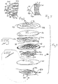
- Fig. 8 is an exploded perspective view of one quadrature coil set showing an RF shield suitable for use with the coil of the invention.
-
- Fig. 1 illustrates a prior art "closed"
MRI system 10 wherein a polarized magnetic field B0 is produced by a cylindrical,annular magnet 12 having abore 14 for admitting a patient along the axis of the cylinder aligned with the magnetic field B0. Precession of nuclei within the patient inbore 14 is induced by an RF field providing a magnetic vector in a plane perpendicular to the B0 axis. This RF field may be produced by a so called "bird cage"coil 16 having an electrically resonant antenna structure that produces a rotating magnetic field within the desired plane. Exemplary bird cage coils are taught in Hayes U.S. Patents 4,692,705, issued Sept. 8, 1987, and 4,694,255, issued Sept. 15, 1987, and Edelstein et al. U.S. Patent 4,680,548, issued July 14, 1987, each of which patent is assigned to the instant assignee and hereby incorporated by reference. The term "coil" is used herein synonymously with the term "antenna" and does not require a coil shape. - Figure 2 illustrates an "open" MRI system 18 which is useful for certain procedures, and particularly for surgical procedures. In this open MRI system,
annular magnet 12 of the closed MRI system shown in Fig. 1 is replaced by opposed magnetic pole faces 20 providing therebetween a relativelyunobstructed opening 22 into which a patient may be placed while preserving greater access to the patient. In the open MRI system, the B0 field extends between pole faces 20 (vertically as depicted) and the RF field is likewise rotated to remain perpendicular to the B0 field. While a bird cage coil, such ascoil 16 of Fig. 1, could be used in this application , such coil is undesirable to the extent that it may unduly restrict the newly opened access to the patient. Therefore, in open MRI systems, one or more arrays of parallel conductors positioned near pole faces 20 may constitute anRF coil 24. Fig. 3 illustratesindividual conductor elements 26 of the opposed RF coils 24 energized with current flowing in opposite directions so as to produce a net RF vector in the desired plane perpendicular to the B0 axis. - While a single opposed pair of RF coils may be used for producing an oscillating RF field along a single line, preferably each
such RF coil 24 is matched to a second array having perpendicularly runningconductor elements 26. For the RF stimulating pulse, the two matched RF coils 24 are energized with signals having a 90 degree phase difference so as to create a rotating RF field as depicted generally in Fig. 2. For reception of the resonance signal, signals detected at the crossing RF coils 24 are combined with the appropriate 90 degree phase difference to produce a signal with superior signal-to-noise ratio. Coils providing for perpendicular reception or transmission patterns are known generally as "quadrature" coils. - A
radio frequency shield 28 may be placed between RF coils 24 and gradient coils 30, as shown in Fig. 3, so as to prevent signal from the gradient coils from interfering with reception of signals by RF coils 24. Each suchradio frequency shield 28 may be used as a return conductor path for a respective RF coil. In order to maintain a high degree of homogeneity for the radio frequency and magnetic fields, pole faces 20 must be situated as close as possible to each other, and therefore RF coils 24 andradio frequency shield 28 should also be as close as possible to each other. - As shown in Fig. 4, an open MRI system in accordance with a preferred embodiment of the invention includes opposed RF coils 24a and 24b situated, respectively, at each
pole face 20, and each coil is composed of two conductor arrays. Thus RF coil 24a includes conductor arrays 32a and 32b while RF coil 24b includesconductor arrays 32c and 32d. Each of conductor arrays 32a-32d is composed, respectively, of a planar set of substantially parallel conductor elements 34a-34d arranged to extend substantially perpendicularly to the polarizing axis B0. Conductor elements 34a and 34c ofconductor arrays 32a and 32c, respectively, are parallel to each other and perpendicular to conductor elements 34b and 34d of conductor arrays 32b and 32d, respectively, so that the conductor arrays of each of RF coils 24a and 24b may produce or detect RF signals in quadrature along mutually perpendicular axes. - Fig. 5 shows each of the ends of conductor elements 34a being connected together by two independent node connectors 36a respectively, with one of the node connectors electrically joining first ends of conductor elements 34a together and the second of the node connectors electrically joining opposing second ends of conductor elements 34a together so that the conductor elements may be attached to nodes 38a and from there to
signal lines 40a. Similar connections are made for array 32b of coil 24a with similar reference numbers and a "b" suffix, and similar connections are also made forarrays 32c and 32d of coil 24b (not shown in Fig. 5). - Each node connector, such as connector 36a, may provide for an equal impedance connection between its node 38 and each of the conductor elements, such as elements 34a, by way of a branching structure as shown in Fig. 6, in which equal length
constant width branches 42 extend from node 38a tosecondary nodes 44 and branch again atsecondary nodes 44 intosecondary branches 46 also of equal length and width and hence equal impedance. Each ofsecondary branches 46 may proceed totertiary nodes 48 to createtertiary branches 50 that ultimately communicate with ends of the conductor elements. Each of the primary, secondary and tertiary branches need only be of equal length within their rank (as primary, secondary and tertiary) so that any path between node 38a and an end of conductor element 34a has the same path length (and cross-sectional configuration) and hence the same impedance. In this way, current is evenly divided among the conductor elements and does not disproportionately flow through the center conductor element of the RF coil. This greatly simplifies construction of the coil, eliminating any need for variable width conductor elements or variation in the spacing of the conductor elements. These latter variations may be reserved for correcting for higher order errors rather than for fundamental differences in current flow. It will also be understood that this branching approach may be used for any number of conductor elements equal to a power of 2. - In an alternative embodiment, shown in Fig. 7, node connector 36a may be a solid sheet of conductor in an isosceles triangle pattern where the apex of the triangle is node 38a and the base connects to the ends of conductor elements 34a. This creates a direct path in a straight line, and hence the shortest possible path, between node 38a and the ends of conductor elements 34a. By allowing these paths to be non-overlapping, resistance between node 38a and each of conductor elements 34a is minimized. For this non-overlapping situation to occur, the height of the isosceles triangle measured from apex to base is substantially greater than three times the width of an average conductor element 34a.
- As shown in Fig. 4, opposed
conductor arrays 32a and 32c having conductor elements 34 oriented in parallel, may be connected in series by interconnection leads 52a and 52b joiningsignal lines 40a and 40c so as to placeconductor arrays 32a and 32c in series in a continuous loop, thus providing for countervailing currents as described with respect to Fig. 3. Anexcitation signal 53a may be applied across a capacitor 54a positioned along this loop formed by interconnections 52a and 52b, or alternatively, a resonance signal may be extracted across capacitor 54a during acquisition of the resonance signal. Similarly, conductor arrays 32b and 32d having parallel oriented conductor elements 34b and 34d may be interconnected by leads 52c and 52d and a signal 53b may be inserted across a series connected capacitor 54b or received across that capacitor in a manner similar to that described above.Conductor arrays 32a and 32c, and 32b and 32d, may alternatively be driven in parallel using properly phased signals, as known in the art, with the advantage of not requiring any direct cabling across the magnet gap - Conductors 52a-52d may comprise coaxial cable and be routed so as to provide greater accessibility to the area between pole faces 20.
- In an alternative embodiment, capacitor 54a or 54b may be centered within one of conductor elements 34a and 34b, or 34c and 34d, respectively, near the edge of the conductor arrays. In this instance, the current conducted by the other conductor elements runs counter to the conductor element having the capacitor for introducing the signal. In this configuration, a separate voltage with 180° phase shift may be provided to the
lower conductor arrays 32c and 32d. This configuration has the disadvantage that the conductor element used for the connection across the capacitor carries current in the opposite direction to the rest of the conductor elements in the array, reducing the strength and uniformity of the generated RF field. -
Signals 53a and 53b will generally have a 90° phase separation and so may be combined by a combiner/splitter 58, shown in Fig. 5, to provide a single quadrature signal on asignal line 60 having an improved signal-to-noise ratio. Combiner/splitter 58 may be a hybrid circuit of a type well known in the art. Likewise, an excitation signal received fromline 60 may be split by combiner/splitter 58 to excite the coils in quadrature for the reverse effect. - As shown in Fig. 8, RF coil 24a may be fabricated by producing conductor arrays 32a and 32b (or 32c and 32d) as etched copper traces on opposite sides of an insulating
substrate 62 according to well-known printed circuit techniques. The conductor arrays thus may comprise copper foil laminated onsubstrate 62. - In Fig. 5, the close proximity of two orthogonal conductor arrays 32a and 32b results in a
parasitic capacitance 64 at each point where conductor elements 34a of conductor array 32a cross conductor elements 34b of conductor array 32b. These parasitic capacitances impair the electrical isolation of conductor arrays 32a and 32b, the condition of isolation being required for maximum signal-to-noise ratio in a quadrature coil. Accordingly, conductor arrays 32a and 32b may be re-isolated by connecting an isolation circuit 66 between conductor arrays 32a and 32b, the isolation circuit having a impedance exactly sufficient to matchparasitic capacitance 64, in this instance through an inductance that creates with capacitance 64 a parallel resonant circuit having a peak impedance at the RF frequency matching the Larmor frequency for which the RF coil is intended. In the event that parasitic inductance (not shown) dominates, isolation circuit 66 may be an adjustable capacitor. Alternatively, isolation circuit 66 may provide a fixed inductance, which is easier to fabricate, and may be adjusted by a parallel or series connected adjustable capacitor to provide the same effect. - In the embodiment shown in Fig. 8, the fixed inductance of the isolation circuit may be connected between node connectors 36a and 36b of conductor arrays 32a and 32b, respectively, through a small hole (not shown) cut in
substrate 62. Conductor arrays 32a and 32b are mounted tosubstrate 62, which may comprise a polyester resin impregnated fiberglass board, and may then be attached to an outer surface of aplanar support structure 67 providing sufficient rigidity to resist the force of a patient placed thereupon (for the lower coil) but having cut-outsections 68 to provide that strength with a reduced amount of material so as to maximize its dielectric constant. Positioned at one side opposite conductor arrays 32a and 32b areRF shields 70a and 70b, fabricated as copper foil traces laminated to an insulatingsubstrate 72 in much the same manner as conductor arrays 32a and 32b are attached tosubstrate 62. RF shields 70a and 70b provide a conductive plane that prevents interference between gradient coils (shown as coils 30 in Fig. 3) and conductor arrays 32a and 32b. While a continuous copper shield would provide such reduction in interference, it would promote conduction of eddy currents, distorting and sapping energy from the gradient coils. Accordingly, shields 70a and 70b includechannels 73 of removed copper material extending parallel to conductor elements 34a of conductor array 32a forshield 70a and parallel to conductor elements 34b of conductor array 32b for shield 70b with the channels positioned in each instance to lie approximately midway between the respective conductor elements.Channels 73 are essentially parallel on each side ofsubstrate 72, but may converge at their ends if the shields are used for return paths per the parallel connection of the conductor arrays. - The RF shielding capability of
shields 70a and 70b is increased by providingsmall capacitances 74bridging channels 73 and adjusted so as to be an open circuit (or high impedance) at the frequencies associated with the gradient coils but a closed circuit (or low impedance) at the much higher frequencies associated with the RF signals. Anequatorial channel 76 may be added, cutting perpendicularly midway across thechannels 73 for further reduction of eddy currents. - The effect of eddy currents from gradient coils 30 on conductor arrays 32a and 32b may be further reduced by a second
equatorial channel 69 severing each of conductor elements 34a and 34b midway along their length. The gaps are again bridged bycapacitive elements 71 selected to be substantially open circuits at the frequencies associated with the gradient coils but closed circuits at the higher RF frequencies associated with RF coil 24a. -
Capacitive elements 71 provide a resonance with the coil at the Larmor frequency of the nuclear spins, turning each conductor element 34a and 34b into a half-wave resonance conductor. In this way,capacitive element 71 also limits build-up of free charge along the conductor surfaces, thus limiting undesirable effects of capacitive coupling between the conductor elements and any of the subject being imaged and other conductive surfaces within the MRI machine. - Increasing the thickness of
support structure 67, which is of a low dielectric material to eliminate dielectric losses, reduces interaction between RF coil 24a and the gradient coils, as does increasing the dielectric constant ofsupport structure 67. However, if the thickness ofsupport structure 67 is too great, the overall coil structure will intrude upon the imaging volume. - Accordingly, it will be understood that an extremely compact coil may be provided for an open frame MRI system with the principal dimension being determined by the
support structure 67 separating conductor arrays 32a and 32b fromshields 70a and 70b on one side of the opening for patient access and by similar support structure separating a second pair of conductor arrays from a second pair of shields on the other side of the opening for patient access.
Claims (15)
- A quadrature coil (24a-24d) for operation at a radio frequency in an open MRI system (18), the MRI system having a polarizing magnet with opposed pole faces (20) for establishing therebetween a polarizing field axis (B0), the coil comprising:a first conductor array (32a) providing separated and substantially aligned conductor elements (34a) positioned along a first conductor axis extending across the polarizing field axis to opposed, common connection points (36a);a second conductor array (32b) providing separated and substantially aligned conductor elements (34b) positioned along a second conductor axis extending across the polarizing field axis to opposed, connection points (36b) and substantially perpendicular to the first conductor elements;a combiner/splitter (58) electrically communicating with a connection point of each of the first and second conductor arrays to join the connection points with a signal line (60) so that a signal path between said signal line and the common connection point of the first conductor array has a substantially 90 degree phase difference from a signal path between the common signal line and the connection point of the second conductor array; andan isolation circuit (66) coupled between the first and second conductor arrays to act as a blocking parallel resonance at the radio frequency.
- The quadrature coil of claim 1 wherein the isolation circuit (66) comprises an adjustable inductor for establishing a parallel resonance in combination with a parasitic capacitive coupling between overlying conductors of the first and second conductor arrays.
- The quadrature coil of claim 1 or 2 wherein the first and second conductor arrays (32a, 32b) comprise copper foil laminated to opposite sides of a planar insulating substrate (62) and wherein the isolation circuit is coupled to adjacent connection points on opposite sides of the planar insulating substrate.
- A radio frequency coil (24a-24d) for an open MRI system (18), the MRI system having a polarizing magnet with opposed pole faces (20) for establishing therebetween a polarizing field axis (B0), the coil comprising:a conductor array (32a) providing separated and substantially aligned conductor elements (34a) positioned along a first conductor axis extending across the polarizing field axis, each conductor element having a first and second end;a first node connection (36a) connecting the first ends of the conductor elements to a first node (38a);a second node connection (36a) connecting the second ends of the conductor elements to a second node (38a);said first and second node connections comprising equal impedance paths between each of the ends and the respective nodes (34a); andan RF signal line (40a) connected to the first and second nodes.
- The radio frequency coil of claim 4 wherein the first and second node connections (36a) provide equal path lengths between each of the ends of the conductor elements and the respective nodes (38a).
- The radio frequency coil of claim 4 wherein the first and second node connections (36a) comprise a first set of separate equal impedance conductive branches (42) extending from each of the single nodes, each conductive branch of the first set further branching into a second set of separate equal impedance branches (46) which ultimately connect with the ends of the conductor elements.
- The radio frequency coil of claim 4 wherein said first and second node connections each comprise substantially non-overlapping straight line paths between the respective ends and the node point.
- The radio frequency coil of claim 7 wherein the substantially non-overlapping straight line paths of each of said first and second node connections are provided by respective continuous isosceles triangular conductors having a respective one of said first and second nodes at the apex of the isosceles triangular conductor and the ends distributed along the base of the isosceles triangular conductor.
- The radio frequency coil of claim 8 wherein the conductor array and the first and second node connections comprise copper foil laminated to opposite sides of a planar insulating substrate (62).
- A quadrature coil (24a-24d) for operation at a radio frequency in an open MRI system (18), the MRI system having a polarizing magnet with opposed pole faces (20) for establishing therebetween a polarizing field axis (B0), the coil comprising:a first conductor array (32a) providing separated and substantially aligned conductor elements (34a) positioned along a first conductor axis extending across the polarizing field axis to opposed connection points;a second conductor array (32b) providing separated and substantially aligned conductor elements (34b) positioned along a second conductor axis extending across the polarizing field axis and substantially perpendicular to the first conductor array to opposed connection points;an RF shield (70a, 70b) positioned between an adjacent pole face and the first and second conductor arrays for providing a conductive surface interrupted by channels (73) substantially aligned with both the first and second conductor axis; anda combiner/splitter (58) electrically communicating with a connection point (38) of each of the first and second conductor arrays to join the connection points with a signal line (60) so that the signal path between said signal line and the connection point of the first conductor array has a substantially 90 degree phase when compared with the signal path between the common signal line and the connection point of the second conductor array.
- The radio frequency coil of claim 10 wherein the channels aligned with the first conductor axis are on a first conductive sheet (70a) and the channels aligned with the second conductive axis are on a second conductive sheet (70b) adjacent to the first conductive sheet.
- The radio frequency coil of claim 10 wherein the channels are bridged by capacitors (74) sized to provide low admittance at the radio frequency.
- The radio frequency coil of claim 11 wherein the first and second conductive sheets (70a, 70b) comprise copper foil laminated to opposite sides of a planar insulating substrate.
- A quadrature coil (24a-24d) for operation at a radio frequency in an open MRI system (18), the MRI system having a polarizing magnet with opposed pole faces (20) for establishing therebetween a polarizing field axis, the coil comprising:whereby current flow direction through the first and third conductor arrays is opposite to current flow direction through the second and fourth conductor arrays, respectively.A.) a first quadrature coil set (24a) positioned at a first pole face and having(a) a first conductor array (32a) providing separated and substantially aligned conductor elements (34a) positioned along a first conductor axis extending across the polarizing field axis to opposed connection points (38a), and(b) a second conductor array (32b) providing separated and substantially aligned conductor elements (34b) positioned along a second conductor axis extending across the polarizing field axis to opposed connection points (38b) in a direction substantially perpendicular to the first conductor array;B.) a second quadrature coil set (24b) positioned at a second pole face and having:(a) a third conductor array (32c) providing separated and substantially aligned conductor elements (34c) positioned along the first conductor axis extending across the polarizing field axis to opposed connection points,(b) a fourth conductor array (32d) providing separated and substantially aligned conductor elements (34d) positioned along the second conductor axis extending across the polarizing field axis to opposed connection points in a direction substantially perpendicular to the first conductor array;C.) interconnection leads (52b, 52a) connecting the first and third conductor arrays in series through their connection points; andD.) interconnection leads (52c, 52d) connecting the second and fourth conductor arrays in series through their connection points;
- The radio frequency coil of claim 14 further including a combiner/splitter (58) joining the interconnection leads of the first and third conductor arrays and the interconnection leads of the second and third conductor arrays so as to promote a respective quadrature current flow between the first and second quadrature coil sets.
Applications Claiming Priority (2)
| Application Number | Priority Date | Filing Date | Title |
|---|---|---|---|
| US455430 | 1999-12-06 | ||
| US09/455,430 US6437567B1 (en) | 1999-12-06 | 1999-12-06 | Radio frequency coil for open magnetic resonance imaging system |
Publications (2)
| Publication Number | Publication Date |
|---|---|
| EP1115005A2 true EP1115005A2 (en) | 2001-07-11 |
| EP1115005A3 EP1115005A3 (en) | 2003-10-08 |
Family
ID=23808773
Family Applications (1)
| Application Number | Title | Priority Date | Filing Date |
|---|---|---|---|
| EP00310654A Withdrawn EP1115005A3 (en) | 1999-12-06 | 2000-11-30 | Radio frequency coil for open magnetic resonance imaging system |
Country Status (5)
| Country | Link |
|---|---|
| US (1) | US6437567B1 (en) |
| EP (1) | EP1115005A3 (en) |
| JP (1) | JP2001198106A (en) |
| KR (1) | KR20010062132A (en) |
| CN (1) | CN1306217A (en) |
Cited By (2)
| Publication number | Priority date | Publication date | Assignee | Title |
|---|---|---|---|---|
| WO2008078269A3 (en) * | 2006-12-20 | 2008-08-28 | Philips Intellectual Property | Arrangement and method for influencing and/or detecting magnetic particles in a region of action, coil arrangement |
| CN104155622B (en) * | 2014-08-26 | 2017-10-03 | 国家电网公司 | A kind of planar radio frequency coils for nuclear magnetic resonance |
Families Citing this family (111)
| Publication number | Priority date | Publication date | Assignee | Title |
|---|---|---|---|---|
| FR2652928B1 (en) | 1989-10-05 | 1994-07-29 | Diadix Sa | INTERACTIVE LOCAL INTERVENTION SYSTEM WITHIN A AREA OF A NON-HOMOGENEOUS STRUCTURE. |
| WO1994004938A1 (en) | 1992-08-14 | 1994-03-03 | British Telecommunications Public Limited Company | Position location system |
| US6226548B1 (en) | 1997-09-24 | 2001-05-01 | Surgical Navigation Technologies, Inc. | Percutaneous registration apparatus and method for use in computer-assisted surgical navigation |
| US6021343A (en) | 1997-11-20 | 2000-02-01 | Surgical Navigation Technologies | Image guided awl/tap/screwdriver |
| US6348058B1 (en) | 1997-12-12 | 2002-02-19 | Surgical Navigation Technologies, Inc. | Image guided spinal surgery guide, system, and method for use thereof |
| US6477400B1 (en) | 1998-08-20 | 2002-11-05 | Sofamor Danek Holdings, Inc. | Fluoroscopic image guided orthopaedic surgery system with intraoperative registration |
| US6470207B1 (en) | 1999-03-23 | 2002-10-22 | Surgical Navigation Technologies, Inc. | Navigational guidance via computer-assisted fluoroscopic imaging |
| US6491699B1 (en) | 1999-04-20 | 2002-12-10 | Surgical Navigation Technologies, Inc. | Instrument guidance method and system for image guided surgery |
| US11331150B2 (en) | 1999-10-28 | 2022-05-17 | Medtronic Navigation, Inc. | Method and apparatus for surgical navigation |
| US6381485B1 (en) | 1999-10-28 | 2002-04-30 | Surgical Navigation Technologies, Inc. | Registration of human anatomy integrated for electromagnetic localization |
| US7366562B2 (en) | 2003-10-17 | 2008-04-29 | Medtronic Navigation, Inc. | Method and apparatus for surgical navigation |
| US8239001B2 (en) | 2003-10-17 | 2012-08-07 | Medtronic Navigation, Inc. | Method and apparatus for surgical navigation |
| US6474341B1 (en) | 1999-10-28 | 2002-11-05 | Surgical Navigation Technologies, Inc. | Surgical communication and power system |
| US6493573B1 (en) | 1999-10-28 | 2002-12-10 | Winchester Development Associates | Method and system for navigating a catheter probe in the presence of field-influencing objects |
| US6499488B1 (en) | 1999-10-28 | 2002-12-31 | Winchester Development Associates | Surgical sensor |
| US8644907B2 (en) | 1999-10-28 | 2014-02-04 | Medtronic Navigaton, Inc. | Method and apparatus for surgical navigation |
| WO2001064124A1 (en) | 2000-03-01 | 2001-09-07 | Surgical Navigation Technologies, Inc. | Multiple cannula image guided tool for image guided procedures |
| GB2360093A (en) * | 2000-03-06 | 2001-09-12 | Marconi Caswell Ltd | NMR system with magnetic flux guide |
| JP3516631B2 (en) * | 2000-03-30 | 2004-04-05 | ジーイー・メディカル・システムズ・グローバル・テクノロジー・カンパニー・エルエルシー | RF coil and magnetic resonance imaging apparatus |
| US6535756B1 (en) | 2000-04-07 | 2003-03-18 | Surgical Navigation Technologies, Inc. | Trajectory storage apparatus and method for surgical navigation system |
| US7085400B1 (en) | 2000-06-14 | 2006-08-01 | Surgical Navigation Technologies, Inc. | System and method for image based sensor calibration |
| JP2002052008A (en) * | 2000-08-08 | 2002-02-19 | Katsumi Kose | Magnetic resonance diagnosing apparatus |
| US6636757B1 (en) * | 2001-06-04 | 2003-10-21 | Surgical Navigation Technologies, Inc. | Method and apparatus for electromagnetic navigation of a surgical probe near a metal object |
| DE10127266C2 (en) * | 2001-06-05 | 2003-12-24 | Siemens Ag | Active NMR transmitter or receiver system |
| JP4496516B2 (en) * | 2002-01-31 | 2010-07-07 | ルネサスエレクトロニクス株式会社 | High frequency wiring |
| US6947786B2 (en) | 2002-02-28 | 2005-09-20 | Surgical Navigation Technologies, Inc. | Method and apparatus for perspective inversion |
| US6990368B2 (en) | 2002-04-04 | 2006-01-24 | Surgical Navigation Technologies, Inc. | Method and apparatus for virtual digital subtraction angiography |
| US7998062B2 (en) | 2004-03-29 | 2011-08-16 | Superdimension, Ltd. | Endoscope structures and techniques for navigating to a target in branched structure |
| US7010834B2 (en) * | 2002-09-10 | 2006-03-14 | Nokia Corporation | Hinge assembly, and associated method, providing multiple axes of rotation |
| US6798204B2 (en) * | 2002-10-09 | 2004-09-28 | Igc - Medical Advances, Inc. | Local RF MRI coil using metal foil construction on a double-sided substrate with holes that directly pass DC conductors |
| AU2003272059A1 (en) * | 2002-10-17 | 2004-05-04 | Ramot At Tel Aviv University Ltd. | A radiofrequency magnetic field resonator and a method of designing the same |
| US7599730B2 (en) | 2002-11-19 | 2009-10-06 | Medtronic Navigation, Inc. | Navigation system for cardiac therapies |
| US7697972B2 (en) | 2002-11-19 | 2010-04-13 | Medtronic Navigation, Inc. | Navigation system for cardiac therapies |
| US7542791B2 (en) | 2003-01-30 | 2009-06-02 | Medtronic Navigation, Inc. | Method and apparatus for preplanning a surgical procedure |
| US7660623B2 (en) | 2003-01-30 | 2010-02-09 | Medtronic Navigation, Inc. | Six degree of freedom alignment display for medical procedures |
| JP3819367B2 (en) * | 2003-02-21 | 2006-09-06 | ジーイー・メディカル・システムズ・グローバル・テクノロジー・カンパニー・エルエルシー | RF shield and MRI equipment |
| US7494596B2 (en) * | 2003-03-21 | 2009-02-24 | Hewlett-Packard Development Company, L.P. | Measurement of etching |
| JP2006525068A (en) * | 2003-05-08 | 2006-11-09 | コーニンクレッカ フィリップス エレクトロニクス エヌ ヴィ | Radio frequency coil system used in magnetic resonance imaging system |
| US6982552B2 (en) * | 2003-05-27 | 2006-01-03 | General Electric Company | Methods and systems for fabricating magnetic resonance gradient coils |
| US7313430B2 (en) | 2003-08-28 | 2007-12-25 | Medtronic Navigation, Inc. | Method and apparatus for performing stereotactic surgery |
| EP2316328B1 (en) | 2003-09-15 | 2012-05-09 | Super Dimension Ltd. | Wrap-around holding device for use with bronchoscopes |
| WO2005025635A2 (en) | 2003-09-15 | 2005-03-24 | Super Dimension Ltd. | System of accessories for use with bronchoscopes |
| US7970452B2 (en) | 2003-09-30 | 2011-06-28 | Hologic, Inc. | Open architecture imaging apparatus and coil system for magnetic resonance imaging |
| US7908690B2 (en) * | 2003-09-30 | 2011-03-22 | Sentinelle Medical, Inc. | Supine patient support for medical imaging |
| US20080077005A1 (en) * | 2004-08-12 | 2008-03-27 | Piron Cameron A | System and Method for Multimodality Breast Imaging |
| US7379769B2 (en) * | 2003-09-30 | 2008-05-27 | Sunnybrook Health Sciences Center | Hybrid imaging method to monitor medical device delivery and patient support for use in the method |
| US7835778B2 (en) | 2003-10-16 | 2010-11-16 | Medtronic Navigation, Inc. | Method and apparatus for surgical navigation of a multiple piece construct for implantation |
| US7840253B2 (en) | 2003-10-17 | 2010-11-23 | Medtronic Navigation, Inc. | Method and apparatus for surgical navigation |
| DE10353343B3 (en) * | 2003-11-14 | 2005-08-25 | Siemens Ag | Magnetic resonance apparatus with a high-frequency screen lying on a reference potential |
| US8764725B2 (en) | 2004-02-09 | 2014-07-01 | Covidien Lp | Directional anchoring mechanism, method and applications thereof |
| US7088100B2 (en) * | 2004-03-11 | 2006-08-08 | General Electric Company | Method and apparatus to generate a circular polarized RF field independent of subject asymmetry |
| US7567834B2 (en) | 2004-05-03 | 2009-07-28 | Medtronic Navigation, Inc. | Method and apparatus for implantation between two vertebral bodies |
| US7102350B2 (en) * | 2004-06-30 | 2006-09-05 | General Electric Company | Shielding apparatus for magnetic resonance imaging |
| US20060025668A1 (en) * | 2004-08-02 | 2006-02-02 | Peterson Thomas H | Operating table with embedded tracking technology |
| GB2419417B (en) * | 2004-10-20 | 2007-05-16 | Gen Electric | Gradient bore cooling and RF shield |
| CN101171526B (en) * | 2005-05-06 | 2012-07-18 | 皇家飞利浦电子股份有限公司 | Electromagnetic shielding for high field MRI coils |
| US7835784B2 (en) | 2005-09-21 | 2010-11-16 | Medtronic Navigation, Inc. | Method and apparatus for positioning a reference frame |
| US9168102B2 (en) | 2006-01-18 | 2015-10-27 | Medtronic Navigation, Inc. | Method and apparatus for providing a container to a sterile environment |
| US8112292B2 (en) | 2006-04-21 | 2012-02-07 | Medtronic Navigation, Inc. | Method and apparatus for optimizing a therapy |
| US8660635B2 (en) | 2006-09-29 | 2014-02-25 | Medtronic, Inc. | Method and apparatus for optimizing a computer assisted surgical procedure |
| US8905920B2 (en) | 2007-09-27 | 2014-12-09 | Covidien Lp | Bronchoscope adapter and method |
| US7940047B2 (en) | 2007-11-23 | 2011-05-10 | Sentinelle Medical, Inc. | Microcontroller system for identifying RF coils in the bore of a magnetic resonance imaging system |
| WO2009074965A1 (en) * | 2007-12-12 | 2009-06-18 | Koninklijke Philips Electronics N.V. | Transmit/receive coil for ultra-high field mri |
| JP2009201886A (en) * | 2008-02-29 | 2009-09-10 | Ge Medical Systems Global Technology Co Llc | Coil, mri apparatus and mri system |
| US9575140B2 (en) | 2008-04-03 | 2017-02-21 | Covidien Lp | Magnetic interference detection system and method |
| EP2297673B1 (en) | 2008-06-03 | 2020-04-22 | Covidien LP | Feature-based registration method |
| US8218847B2 (en) | 2008-06-06 | 2012-07-10 | Superdimension, Ltd. | Hybrid registration method |
| US8932207B2 (en) | 2008-07-10 | 2015-01-13 | Covidien Lp | Integrated multi-functional endoscopic tool |
| US8165658B2 (en) | 2008-09-26 | 2012-04-24 | Medtronic, Inc. | Method and apparatus for positioning a guide relative to a base |
| US8175681B2 (en) | 2008-12-16 | 2012-05-08 | Medtronic Navigation Inc. | Combination of electromagnetic and electropotential localization |
| US8611984B2 (en) | 2009-04-08 | 2013-12-17 | Covidien Lp | Locatable catheter |
| EP2445413B1 (en) * | 2009-06-23 | 2020-02-12 | Invivo Corporation | Variable angle guide holder for a biopsy guide plug |
| US8494614B2 (en) | 2009-08-31 | 2013-07-23 | Regents Of The University Of Minnesota | Combination localization system |
| US8494613B2 (en) | 2009-08-31 | 2013-07-23 | Medtronic, Inc. | Combination localization system |
| JP5497785B2 (en) * | 2009-11-27 | 2014-05-21 | 株式会社日立メディコ | Gradient magnetic field coil and nuclear magnetic resonance imaging apparatus |
| US8258789B2 (en) * | 2009-12-21 | 2012-09-04 | General Electric Company | Apparatus and method for decoupling MR coils |
| CN101856229B (en) * | 2010-04-22 | 2013-04-24 | 杜健军 | Radio-frequency coil device in magnetic resonance imaging system |
| WO2011159834A1 (en) | 2010-06-15 | 2011-12-22 | Superdimension, Ltd. | Locatable expandable working channel and method |
| GB2483890A (en) * | 2010-09-22 | 2012-03-28 | Tesla Engineering Ltd | MRIS gradient coil assembly with screening layers connected to respective coil layers |
| DE102010041202B4 (en) * | 2010-09-22 | 2014-03-06 | Siemens Aktiengesellschaft | Magnetic resonance apparatus, reflector array and high-frequency shielding system for a magnetic resonance apparatus |
| US9913596B2 (en) | 2010-11-25 | 2018-03-13 | Invivo Corporation | Systems and methods for MRI guided trans-orifice and transperineal intervention apparatus with adjustable biopsy needle insertion |
| US8890529B2 (en) * | 2011-05-31 | 2014-11-18 | General Electric Company | System and apparatus for providing interconnections in a gradient coil assembly |
| US9285441B1 (en) * | 2011-06-08 | 2016-03-15 | Abqmr, Inc. | Magnetic field correction system |
| RU2595798C2 (en) * | 2011-10-18 | 2016-08-27 | Конинклейке Филипс Н.В. | Reel assembly of nuclear magnetic resonance with radio frequency screen switchable between locking state and transparent state |
| US20150008924A1 (en) * | 2012-02-01 | 2015-01-08 | Koninklike Philips N.V. | Nanoparticle rf shield for use in an mri device |
| US8659297B2 (en) * | 2012-02-27 | 2014-02-25 | Perinatronics Medical Systems, Inc. | Reducing noise in magnetic resonance imaging using conductive loops |
| CN103837848B (en) * | 2012-11-27 | 2017-05-17 | 朱宇东 | Radio frequency antenna device for magnetic resonance system and method |
| ES2961685T3 (en) | 2013-03-15 | 2024-03-13 | Hologic Inc | System and method of review and analysis of cytological samples |
| CN104076305B (en) | 2013-03-29 | 2018-02-13 | 西门子(深圳)磁共振有限公司 | A kind of debugging apparatus of the body coil of magnetic resonance imaging system |
| DE102013205817A1 (en) * | 2013-04-03 | 2014-10-09 | Siemens Aktiengesellschaft | Transmission arrangement for a tomograph |
| US10952593B2 (en) | 2014-06-10 | 2021-03-23 | Covidien Lp | Bronchoscope adapter |
| CN104698411B (en) * | 2015-02-13 | 2018-06-22 | 江苏麦格思频仪器有限公司 | For the Multi-channel radio-frequency coil of open type magnetic resonance imaging (MRI) system |
| US10426555B2 (en) | 2015-06-03 | 2019-10-01 | Covidien Lp | Medical instrument with sensor for use in a system and method for electromagnetic navigation |
| RU2601373C1 (en) * | 2015-07-03 | 2016-11-10 | федеральное государственное автономное образовательное учреждение высшего образования "Санкт-Петербургский национальный исследовательский университет информационных технологий, механики и оптики" (Университет ИТМО) | Magnetic resonance tomographic scanner |
| US9962134B2 (en) | 2015-10-28 | 2018-05-08 | Medtronic Navigation, Inc. | Apparatus and method for maintaining image quality while minimizing X-ray dosage of a patient |
| CN105807242B (en) * | 2016-05-03 | 2018-08-10 | 北京大学 | A kind of open coil device for magnetic resonance imaging |
| US10478254B2 (en) | 2016-05-16 | 2019-11-19 | Covidien Lp | System and method to access lung tissue |
| EP3499529A4 (en) | 2016-08-10 | 2020-04-29 | IUCF-HYU (Industry-University Cooperation Foundation Hanyang University) | Magnetic field control system |
| US10638952B2 (en) | 2016-10-28 | 2020-05-05 | Covidien Lp | Methods, systems, and computer-readable media for calibrating an electromagnetic navigation system |
| US10418705B2 (en) | 2016-10-28 | 2019-09-17 | Covidien Lp | Electromagnetic navigation antenna assembly and electromagnetic navigation system including the same |
| US10615500B2 (en) | 2016-10-28 | 2020-04-07 | Covidien Lp | System and method for designing electromagnetic navigation antenna assemblies |
| US10722311B2 (en) | 2016-10-28 | 2020-07-28 | Covidien Lp | System and method for identifying a location and/or an orientation of an electromagnetic sensor based on a map |
| US10517505B2 (en) | 2016-10-28 | 2019-12-31 | Covidien Lp | Systems, methods, and computer-readable media for optimizing an electromagnetic navigation system |
| US10751126B2 (en) | 2016-10-28 | 2020-08-25 | Covidien Lp | System and method for generating a map for electromagnetic navigation |
| US10446931B2 (en) | 2016-10-28 | 2019-10-15 | Covidien Lp | Electromagnetic navigation antenna assembly and electromagnetic navigation system including the same |
| US10792106B2 (en) | 2016-10-28 | 2020-10-06 | Covidien Lp | System for calibrating an electromagnetic navigation system |
| US10478087B2 (en) * | 2017-02-16 | 2019-11-19 | Aselsan Elektronik Sanayi Ve Ticaret A.S. | Open bore field free line magnetic particle imaging system |
| US11219489B2 (en) | 2017-10-31 | 2022-01-11 | Covidien Lp | Devices and systems for providing sensors in parallel with medical tools |
| WO2021071938A2 (en) * | 2019-10-08 | 2021-04-15 | Hyperfine Research, Inc. | System and methods for detecting electromagnetic interference in patients during magnetic resonance imaging |
| CN112540332B (en) * | 2020-12-03 | 2023-11-14 | 深圳航天科技创新研究院 | Magnetic resonance radio frequency shielding structure and design method thereof |
| CN114535833A (en) * | 2022-03-15 | 2022-05-27 | 深圳软动智能控制有限公司 | Metal cutting equipment and metal cutting method |
Citations (2)
| Publication number | Priority date | Publication date | Assignee | Title |
|---|---|---|---|---|
| US5467017A (en) * | 1992-09-30 | 1995-11-14 | Siemens Aktiengesellschaft | Antenna arrangement for a nuclear magnetic resonance apparatus |
| EP1059539A2 (en) * | 1999-05-17 | 2000-12-13 | General Electric Company | RF Body Coil for an open MRI system |
Family Cites Families (7)
| Publication number | Priority date | Publication date | Assignee | Title |
|---|---|---|---|---|
| US4694255A (en) | 1983-11-04 | 1987-09-15 | General Electric Company | Radio frequency field coil for NMR |
| US4692705A (en) | 1983-12-23 | 1987-09-08 | General Electric Company | Radio frequency field coil for NMR |
| US4680548A (en) | 1984-10-09 | 1987-07-14 | General Electric Company | Radio frequency field coil for NMR |
| GB2221995B (en) | 1988-08-19 | 1992-12-09 | Picker Int Ltd | Magnetic resonance methods and apparatus |
| US5386191A (en) * | 1993-03-01 | 1995-01-31 | The Regents Of The University Of California | RF coil providing reduced obstruction access to image volume in transverse magnet MRI system |
| US5682098A (en) * | 1996-01-11 | 1997-10-28 | W. L. Gore & Associates, Inc. | Open quadrature whole volume imaging NMR surface coil array including three figure-8 shaped surface coils |
| RU98106937A (en) * | 1998-04-14 | 2000-02-10 | Пикер Нордстар ОЮ (FI) | DEVICE FOR IMAGE FORMATION USING MAGNETIC RESONANCE |
-
1999
- 1999-12-06 US US09/455,430 patent/US6437567B1/en not_active Expired - Fee Related
-
2000
- 2000-11-30 EP EP00310654A patent/EP1115005A3/en not_active Withdrawn
- 2000-12-05 JP JP2000369365A patent/JP2001198106A/en not_active Withdrawn
- 2000-12-05 KR KR1020000073291A patent/KR20010062132A/en not_active Application Discontinuation
- 2000-12-06 CN CN00135095A patent/CN1306217A/en active Pending
Patent Citations (2)
| Publication number | Priority date | Publication date | Assignee | Title |
|---|---|---|---|---|
| US5467017A (en) * | 1992-09-30 | 1995-11-14 | Siemens Aktiengesellschaft | Antenna arrangement for a nuclear magnetic resonance apparatus |
| EP1059539A2 (en) * | 1999-05-17 | 2000-12-13 | General Electric Company | RF Body Coil for an open MRI system |
Non-Patent Citations (1)
| Title |
|---|
| BOSKAMP E B ET AL: "VERTICAL FIELD OPEN RF BODY COILS" PROCEEDINGS OF THE INTERNATIONAL SOCIETY FOR MAGNETIC RESONANCE IN MEDICINE. SCIENTIFIC MEETING AND EXHIBITION, XX, XX, vol. 1, 22 May 1999 (1999-05-22), page 736 XP002140446 * |
Cited By (3)
| Publication number | Priority date | Publication date | Assignee | Title |
|---|---|---|---|---|
| WO2008078269A3 (en) * | 2006-12-20 | 2008-08-28 | Philips Intellectual Property | Arrangement and method for influencing and/or detecting magnetic particles in a region of action, coil arrangement |
| US8264220B2 (en) | 2006-12-20 | 2012-09-11 | Koninklijke Philips Electronics N.V. | Arrangement and method for influencing and/or detecting magnetic particles in a region of action using coil arrangement having a surrounding coil that almost completely surrounds a magnetic field generator |
| CN104155622B (en) * | 2014-08-26 | 2017-10-03 | 国家电网公司 | A kind of planar radio frequency coils for nuclear magnetic resonance |
Also Published As
| Publication number | Publication date |
|---|---|
| EP1115005A3 (en) | 2003-10-08 |
| CN1306217A (en) | 2001-08-01 |
| JP2001198106A (en) | 2001-07-24 |
| KR20010062132A (en) | 2001-07-07 |
| US6437567B1 (en) | 2002-08-20 |
Similar Documents
| Publication | Publication Date | Title |
|---|---|---|
| US6437567B1 (en) | Radio frequency coil for open magnetic resonance imaging system | |
| US7710117B2 (en) | Multi-current elements for magnetic resonance radio frequency coils | |
| US4721913A (en) | NMR local coil network | |
| US4746866A (en) | High-frequency coil system for a magnetic resonance imaging apparatus | |
| US5696449A (en) | RF coil for open MR magnet | |
| US7268554B2 (en) | RF coil for imaging system | |
| US5153517A (en) | Surface resonator for a magnetic resonance imaging apparatus | |
| US7091721B2 (en) | Phased array local coil for MRI imaging having non-overlapping regions of sensitivity | |
| US4766383A (en) | Quadrature antenna for magnetic resonance imaging using elliptical coils | |
| US6008649A (en) | RF coil apparatus for MR system with lateral B0 field | |
| US5682098A (en) | Open quadrature whole volume imaging NMR surface coil array including three figure-8 shaped surface coils | |
| US7088104B2 (en) | MRI tunable antenna and system | |
| US4594566A (en) | High frequency rf coil for NMR device | |
| US6215307B1 (en) | Coils for magnetic resonance imaging | |
| US5467017A (en) | Antenna arrangement for a nuclear magnetic resonance apparatus | |
| EP1363135A2 (en) | Method and apparatus for decoupling of detector elements in a RF detector array for magnetic resonance imaging | |
| US6121776A (en) | Superconducting hybrid-resonator for receiving NMR-signals | |
| US7282916B2 (en) | Time-variable magnetic fields generator and magnetic resonance apparatus embodying same | |
| JPH02249531A (en) | Nuclear magnetic resonance method and apparatus | |
| US9520636B2 (en) | Linear resonator of a high-frequency antenna for a nuclear magnetic resonance imaging apparatus | |
| CN104698411B (en) | For the Multi-channel radio-frequency coil of open type magnetic resonance imaging (MRI) system | |
| GB2151791A (en) | RF Field coils for NMR apparatus | |
| WO2018115223A1 (en) | Rf coil device and rf shield device for different mri modes | |
| EP0565178B1 (en) | Quadrature coil system for use in a magnetic resonance apparatus | |
| JP4309095B2 (en) | MR apparatus having open magnet system and orthogonal coil system |
Legal Events
| Date | Code | Title | Description |
|---|---|---|---|
| PUAI | Public reference made under article 153(3) epc to a published international application that has entered the european phase |
Free format text: ORIGINAL CODE: 0009012 |
|
| AK | Designated contracting states |
Kind code of ref document: A2 Designated state(s): AT BE CH CY DE DK ES FI FR GB GR IE IT LI LU MC NL PT SE TR |
|
| AX | Request for extension of the european patent |
Free format text: AL;LT;LV;MK;RO;SI |
|
| RIC1 | Information provided on ipc code assigned before grant |
Ipc: 7G 01R 33/341 B Ipc: 7G 01R 33/36 B Ipc: 7G 01R 33/34 A |
|
| PUAL | Search report despatched |
Free format text: ORIGINAL CODE: 0009013 |
|
| AK | Designated contracting states |
Kind code of ref document: A3 Designated state(s): AT BE CH CY DE DK ES FI FR GB GR IE IT LI LU MC NL PT SE TR |
|
| AX | Request for extension of the european patent |
Extension state: AL LT LV MK RO SI |
|
| 17P | Request for examination filed |
Effective date: 20040408 |
|
| AKX | Designation fees paid |
Designated state(s): DE NL |
|
| 17Q | First examination report despatched |
Effective date: 20070320 |
|
| STAA | Information on the status of an ep patent application or granted ep patent |
Free format text: STATUS: THE APPLICATION IS DEEMED TO BE WITHDRAWN |
|
| 18D | Application deemed to be withdrawn |
Effective date: 20070731 |