-
The present invention generally relates to implantable cardiac
stimulation devices, e.g., pacemakers or implantable cardioverter
defibrillators (ICDs). The present invention more particularly relates to an
implantable cardiac stimulation device and method which provide pacing of
a heart in different modalities while assisting in the treatment of atrial
arrhythmias by prolonging atrial refractoriness of the heart.
-
Atrial arrhythmias such as paroxysmal atrial fibrillation and flutter are
very common arrhythmias. Such arrhythmias are present in a large
percentage of the bradycardia pacemaker patient population. For these
patients, pacemaker therapy could become a primary indication for
treatment of the disorder.
-
The prolongation of atrial refractoriness is known to reduce the
likelihood of atrial arrhythmias in some patients. Certain drugs, such as
amiodarone or beta-blockers, like sotalol, help to maintain sinus rhythm by
prolonging atrial refractoriness and thus act to reduce atrial arrhythmias in
some patients. Other drugs help slow the ventricular rate once atrial
fibrillation has occurred. These drugs reduce ventricular rate by AV nodal
inhibition. These include verapamil, diltiazem, beta-blockers, and/or
digoxin. However, drugs can cause side effects and many patients are
resistant to drug therapy.
-
It would therefore be desirable to have some means other than the
ingestion of drugs available to this patient population for prolonging atrial
refractoriness. To that end, preemptive electrical stimulation of the atrium
is known to prevent atrial arrhythmias in some patients. The present
invention addresses these issues in the form of an implantable cardiac
stimulation device capable of pacing the heart of a patient in single or dual
chamber modalities while pacing the atria in an improved manner which
assists in prolonging atrial refractoriness and treating atrial arrhythmias.
Furthermore, the present invention provides therapeutic benefit to patients
with hypertension, heart failure, acute myocardial infarction and other
disorders as described below.
-
Others have sought to prevent the onset of atrial arrhythmias with
pacing. For example, U.S. Patent No. 5,403,356 to Hill uses at least two
electrode pairs with one electrode pair being used to detect a
depolarization at a one site, e.g., the high right atrium and detection triggers
stimulation to the triangle of Koch or a site of prolonged effective refractory
period. The triggered stimulation occurs synchronous with the detection or
following a short time delay of less than 50 ms. This short time delay is
used to prevent stimulation during the vulnerable period in the atrium and
thus avoids precipitating atrial arrhythmias. Although stimulation at the
triangle of Koch is intended to synchronize the atrium and the refractory
periods in the atrium, it is not intended to act to prolong atrial refractory
periods. Furthermore, this approach requires implantation of multiple atrial
leads and thus complicates the process of administering therapy.
-
Atrial tachyarrhythmias are often preceded by at least one atrial
premature beat that spontaneously originates from an ectopic site in the
atrium. Mehra has proposed in U.S. Patent No. 5,683,429 using burst
pacing at multiple sites immediately after an atrial premature beat to
prevent a reentry event precipitated by the atrial premature beat. Mehra
also teaches that there may be an unspecified time delay between the atrial
premature beat and the burst of pacing. Although this algorithm was
intended to block reentry as a result of atrial premature beats, it does not
act to prevent atrial premature beats and the potentially ensuing atrial
arrhythmias.
-
The present invention further acts to prevent atrial premature beats
by making the ectopic foci responsible for the atrial premature beat
refractory and thus incapable of spontaneously depolarizing.
-
Furthermore, the present invention has the effect of prolonging the
interval between the pacing atrial events and succeeding spontaneous
native atrial depolarizations. This actually makes it possible to reduce the
hemodynamically effective cardiac rate to a rate lower than the native rate
which is useful for regulating blood pressure. This will benefit patients with
essential hypertension, and patients with heart failure in whom reducing
blood pressure reduces cardiac work and reduces ventricular wall tension.
Reducing the ventricular wall tension allows the heart to assume a smaller
more normal geometry and thus allows for more effective contraction.
-
Slowing the hemodynamically effective rate below the native rate
has significant benefits to patients with coronary heart disease. Perfusion
of the myocardium takes place during diastole and thus slowing the rate
increases the diastolic interval and thus allows more time for perfusion of
ischemic cardiac tissue.
-
A further therapeutic application of the present invention is in the
treatment of patients with diastolic dysfunction. These patients have
hypertrophied hearts with reduced compliance. Reducing the effective
hemodynamic rate has the benefit of allowing more time for filling the
relatively stiff, incompliant ventricles and thus enhances stroke volume and
cardiac performance.
-
Other therapeutic benefits are likely to become apparent with
extensive practice of the present invention.
-
The invention therefore provides an implantable cardiac stimulation
device, e.g., a pacemaker or ICD, including generating means for
delivering pacing pulses to an atrium of a heart and control means
coupled to the generating means for causing the generating means to
deliver a primary pacing pulse to the atrium and causing the generating
means to deliver a secondary pacing pulse to the atrium a delay time
after the delivery of the primary pacing pulse.
-
Preferably the implantable cardiac stimulation device further
includes:
- AV delay timing means for timing an AV delay interval responsive
to the delivery of a primary pacing pulse; and
- second generating means responsive to the AV delay timing means
for providing a ventricular pacing pulse at the end of the AV delay interval
and preferably ventricular activation detecting means for detecting
ventricular activations of the heart and ventricular inhibiting means for
inhibiting the second generating means when a ventricular activation is
detected during the AV delay interval.
-
-
Preferably the implantable cardiac stimulation device further
includes timing means for timing the delay time, wherein the delay time is
preferably between about 180 milliseconds and 300 milliseconds.
-
In accordance with further aspects of the present invention, the
implantable cardiac stimulation device may further include a detector that
detects atrial activations of the heart, wherein the generator control
inhibits the generator from providing the primary pacing pulse when an
atrial activation is detected during an escape interval and wherein the
generator control further causes the generator to deliver the secondary
pacing pulse to the atrium the delay time after an atrial activation is
detected during the escape interval.
-
The implantable cardiac stimulation device preferably further
includes AV delay timing means for timing an AV delay interval
responsive to the delivery of a primary pacing pulse or the detection of an
atrial activation within the escape interval; and
second generating means responsive to the AV delay timing means
for providing a ventricular pacing pulse at the end of the AV delay interval
and preferably further includes ventricular activation detecting means for
detecting ventricular activations of the heart and ventricular inhibiting
means for inhibiting the second generating means when a ventricular
activation is detected during the AV delay interval.
-
In accordance with still further aspects of the present invention, the
implantable cardiac stimulation device may further include an AV delay
timer that times an AV delay interval responsive to the delivery of a
primary pacing pulse or the detection of an atrial activation within the
escape interval, and a second generator responsive to the AV delay timer
that provides a ventricular pacing pulse at the end of the AV delay
interval.
-
In accordance with still further aspects of the present invention, the
implantable cardiac stimulation device may further include a ventricular
detector that detects ventricular activations of the heart and a ventricular
inhibitor that inhibits the second generator when a ventricular activation is
detected during the AV delay interval.
-
The present invention still further provides a method of pacing atria
of a heart. The method includes the steps of delivering a primary pacing
pulse to one of the atria of the heart, timing a delay time period following
the delivery of the primary pacing pulse, and delivering a secondary pacing
pulse to the one of the atria at the end of the delay time period.
-
The method preferably further includes the following features:
the method wherein the delay time period is between about 180
milliseconds and 300 milliseconds, the method additionally comprising the
step of detecting the presence of a P-wave and designating the detected
P-wave as the primary atrial event; the method additionally comprising
delivering a primary pacing pulse to the atrium of the patients heart,
wherein the primary atrial pacing pulse is designated as the primary atrial
event; the method additionally comprising the step of timing an AV delay
time period following the primary atrial event and delivering a ventricular
pacing pulse to a ventricle of the patient's heart at the end of the AV
delay time period; the method additionally comprising the step of
detecting ventricular activations of the patient's heart and inhibiting the
delivery of the ventricular pacing pulse to the ventricle when a ventricular
event is detected during the AV delay time period; the method additionally
comprising the steps of:
- detecting atrial activations of the patient's heart;
- timing an atrial escape interval;
- inhibiting the delivery of the primary atrial pacing pulse
when an atrial activation is detected during the atrial escape interval; and
- timing the delay time period upon detecting an atrial
activation during the atrial escape interval;
- the method additionally comprising the steps of:
- setting the delay time period to a predetermined maximum
value;
- sensing, following the delivery of each secondary atrial
pacing pulse, whether a ventricular depolarization occurred; and
- decreasing the delay time period by a predetermined
amount if a ventricular depolarization was sensed in response to the
secondary atrial pacing pulse, and preferably wherein the step of
decreasing the delay time period is bypassed if the decreasing step would
decrease the delay time below a predetermined minimum value and/or
wherein the step of setting the delay time period to a predetermined
maximum value occurs periodically; the method wherein the step of
delivering the secondary atrial pacing pulse is limited to predefined time
periods, and preferably wherein the predefined time periods include
those time periods when the patient is at rest or wherein the predefined
time periods include a period of time following detection of a high
incidence of premature atrial contractions.
-
-
The present invention also discloses a means to automatically
establish the delay timing of delivery of the secondary atrial pulse. The
advantage of automated adjustment of the delivery of the secondary pacing
pulse is that there is no necessity to manually adjust the interval.
Additionally, if there are physiologic changes to the patients heart that
would necessitate adjustment of the delay it will be automatically performed
by the device thus automatically optimizing therapy.
-
Embodiments of the invention will now be described, by way of
example, with reference to the drawings, in the several figures of which like
reference characters identify identical elements, and wherein:
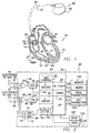
- FIG. 1 is a schematic illustration of a human heart, in need of
cardiac rhythm management, shown in association with an implantable
pacemaker embodying the present invention.
- FIG. 2 is a block diagram of the implantable pacemaker of FIG. 1.
- FIGS. 3 and 4 are cardiac electrograms that illustrate the affects of
adjusting the delay between the primary and secondary atrial pulses.
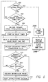
- FIG. 5 is a simplified flowchart of an exemplary implementation of
the method of the present invention.
- FIG. 6 is a simplified flowchart of an exemplary process for
automatically adjusting the atrial delay time between a primary atrial event
and delivery of the secondary atrial pacing pulse if a ventricular
depolarization occurs in response to the secondary atrial pacing pulse.
- Referring now to FIG. 1, a heart 10 in need of cardiac rhythm
management and an associated implantable pacemaker 30 embodying the
present invention are shown. The portions of the heart 10 illustrated in
FIG. 1 are the right ventricle 12, the left ventricle 14, the right atrium 16 and
the left atrium 18. Also illustrated are the superior vena cava 20 and
inferior vena cava 27. As is well known in the art, the pacemaker 30 is
arranged to be implanted in an upper left chest portion of a patient within a
subcutaneous pocket.
-
-
The pacemaker 30 includes a first endocardial lead 32 preferably
having an electrode pair including a distal electrode 34 and a proximal
electrode 36 implanted in electrical contact with an atrium of the patient's
heart. The electrodes 34 and 36 are implanted in the right atrium 16 to
support sensing of right atrial electrical activity and delivery of pacing
pulses to the right atrium 16.
-
Similarly, a second endocardial lead 38 preferably has an electrode
pair including a distal electrode 40 and a proximal electrode 42 implanted in
electrical contact with a ventricle of the patient's heart. The electrodes 40
and 42 are implanted in the right ventricle 12 to support sensing of right
ventricular electrical activity and delivery of pacing pulses to the right
ventricle 12.
-
The implantable pacemaker 30 includes a hermetically sealed,
electrically conductive enclosure 50. As illustrated in FIG. 2, the
pacemaker 30 includes within the enclosure 50 an atrial sense channel 52,
a ventricular sense channel 62, and a pacing pulse generator 70 including
a first or atrial pulse generator 72 (A Gen) for providing atrial pacing pulses
and a second or ventricular pulse generator 74 (V Gen) for providing
ventricular pacing pulses. The pacemaker 30 further includes a control
circuit 80, preferably a microprocessor, a memory 100 and a telemetry
stage 120.
-
The atrial sense channel 52 includes an atrial sense amplifier 54
and an atrial threshold detector 56. The atrial sense amplifier 54 has inputs
coupled to electrodes 34 and 36 of lead 32 and generates an output signal
55 which is input to the atrial threshold detector 56. As further illustrated
the atrial threshold detector 56 has an output 57 which is coupled to the
microprocessor 80.
-
The atrial sense amplifier 54, together with electrodes 34 and 36
sense electrical activity in the right atrium 16. When the output 55 from the
atrial sense amplifier 54 transitions through a programmed threshold of the
atrial threshold detector 56, the atrial threshold detector 56 provides input
signal 57 to the microprocessor 80 indicating that an atrial activation or P-wave
has been detected. Such detection is well known in the art.
-
Similarly, the ventricular sense channel 62 includes a ventricular
sense amplifier 64 and a ventricular threshold detector 66. The ventricular
sense amplifier 64 has inputs coupled to the electrodes 40 and 42 of lead
38 and generates an output signal 65 which is input to the ventricular
threshold detector 66. As further illustrated, the ventricular threshold
detector 66 has an output 67 which is coupled to the microprocessor 80.
-
The ventricular sense amplifier 64, together with electrodes 40 and
42 sense electrical activity in the right ventricle 12. When the output 65 of
the ventricular sense amplifier 64 transitions through a programmed
threshold of the ventricular threshold detector 66, the ventricular threshold
detector 66 provides an input signal 67 to the microprocessor 80 indicating
that a ventricular activation or R-wave has been detected. Such detection
is also well known in the art.
-
The first, or atrial pulse generator 72 has outputs coupled to
electrodes 34 and 36 through lead 32. This permits pacing pulses
produced by the atrial pulse generator 72 to be applied to the right atrium
16. As will be seen hereinafter, these pacing pulses include primary atrial
pacing stimulation pulses (As1) and secondary atrial pacing stimulation
pulses (AS2).
-
The second or ventricular pulse generator 74 has outputs coupled to
electrodes 40 and 42 through lead 38. This permits pacing pulses
produced by the ventricular pulse generator 74 to be applied to the right
ventricle 12.
-
The sense channels 52 and 62 and pulse generators 72 and 74
permit the pacemaker 30, in accordance with the present invention, to
provide single chamber atrial pacing or combined dual chamber atrial and
ventricular pacing. The overall functioning of the pacemaker 30 is
controlled by the microprocessor 80.
-
The microprocessor 80 implements selected pacing modalities by
executing operating instructions stored in the memory 100, and more
specifically, in a memory portion 102. In executing the instructions stored
in memory portion 102, the microprocessor 80 further utilizes pacing
parameters stored in memory portion 104 and detection parameters stored
in memory portion 106. The pacing parameters may include, for example,
AV delays, atrial and ventricular pacing energies, atrial and ventricular
escape intervals, and basic rates, etc. The detection parameters may
include, for example, blanking period durations, refractory periods, and
detection thresholds for the threshold detectors 56 and 66. Such pacing
parameters and detection parameters are well known in the art.
-
The telemetry stage 120 permits mode selections and storage of
pacing and detection parameters in the memory 100 to be made through
the use of an external programmer (not shown) of the type well known in
the art. The telemetry stage includes a receiver 122 which receives
telemetry commands including mode selection commands and pacing and
detection parameters from the programmer. The receiver 122 conveys the
commands to the microprocessor 80 which then stores them in memory
100.
-
The telemetry stage 120 also includes a transmitter 124. The
transmitter may be used for transmitting data to the programmer. The
transmitted data may include sensed electrograms or status information, for
example, as is well known in the art.
-
The microprocessor 80 is coupled to the memory 100 by a multiple-bit
address bus 108 and a bi-directional, multiple-bit data bus 110. The
microprocessor 80 uses the address bus 108 to fetch operating instructions
or programmable parameters from the memory at address locations
defined on the address bus 108. The fetched instructions and parameters
are conveyed to the microprocessor 80 over the data bus 110. Similarly,
the microprocessor 80 may store data in the memory 100 at memory
locations defined on the address bus 108. The microprocessor 80 conveys
the data to the memory over the data bus 110. Such microprocessor and
memory operations are conventional in the art.
-
When executing the operating instructions stored in memory 100,
the microprocessor 80 implements a number of functional stages in
accordance with the present invention. Those stages include a generator
control stage 82 which includes an atrial generator inhibiting stage 84, a
ventricular generator inhibiting stage 86, a primary atrial pacing pulse
stimulation control 88 (AS1), a secondary atrial pacing pulse stimulation
control 90 (AS2), and a ventricular pacing pulse stimulation control 92 (V).
The stages of microprocessor 80 further include an atrial delay timer 94
and an AV delay timer 96.
-
In accordance with a primary aspect of the present invention,
whether the pacemaker 30 is in a single or dual chamber pacing modality,
the generator control stage 82 causes the atrial pulse generator 72 to
provide a secondary atrial pacing pulse to the right atrium 16 a secondary
pacing pulse delay time after causing the atrial pulse generator 72 to
provide a primary atrial pacing pulse to the right atrium 16. When atrial
pacing is in a demand mode, the generator control stage 82 inhibits the
atrial pulse generator 72, and thus the delivery of the primary pacing pulse
if an atrial event, i.e., depolarization signifying activation of the atrium, is
detected during an atrial escape interval. However, the generator control
stage 82 still causes the atrial pulse generator 72 to deliver the secondary
pulse after the secondary pacing pulse delay time following detection of the
atrial event. The secondary pacing pulse prolongs the refractoriness of the
atria. The secondary pacing pulse delay time period, i.e., the period of time
between the primary atrial pacing pulse or the detected atrial depolarization
and the secondary atrial pacing pulse, is preferably between about 180 to
300 milliseconds. The atrial refractory period is typically about 130
milliseconds in normal patients but may be as short as 80 milliseconds in
some patients with recurrent atrial arrhythmias. Accordingly, the secondary
pacing pulse will serve to prolong the period during which the atria are
refractory and thus decrease the likelihood of a spontaneous reentrant
arrhythmia. The ventricle and the AV node will be refractory when the
secondary atrial pacing pulse is delivered. As a result, the secondary atrial
pulse will have no affect on the ventricle. Atrial kick will be provided by the
primary depolarization and it is likely that the atria will be in hemodynamic
block. Thus, the hemodynamics will not be disturbed by the secondary
atrial pacing pulse.
-
As previously mentioned, the atrial pacing may be in a demand
mode. To that end, the atrial generator inhibiting stage 84 preferably
includes an atrial delay timer 94 for timing an atrial escape interval. If,
during the atrial escape interval, the atrial sense channel 52 detects an
atrial event, the atrial generator inhibiting stage 84 will preclude the primary
atrial pulse stimulation control 88 from issuing a control signal to the atrial
pulse generator 72 and thus will inhibit delivery of the primary pacing pulse.
However, upon detection of an atrial event by the atrial sense channel 52,
the atrial delay timer 94 begins timing the secondary pacing pulse delay
period. At the end of the secondary pacing pulse delay time period, the
secondary atrial pacing pulse stimulation control 90 issues a control signal
to the atrial pulse generator 72 to cause it to provide the secondary pacing
pulse.
-
If an atrial event is not detected by the atrial sense channel 52
during the atrial escape interval, the primary atrial pacing pulse stimulation
control 88 issues a control signal to the atrial pulse generator 72 at the end
of the atrial escape interval to cause it to provide the primary pacing pulse.
When the primary pacing pulse is provided by atrial pulse generator 72, the
atrial delay timer 94 commences to time the secondary pacing pulse delay
time period. At the end of the secondary pacing pulse delay time, the
secondary atrial pacing pulse stimulation control 90 then issues a control
signal to the atrial pulse generator 72 to cause the generator 72 to provide
the secondary pacing pulse.
-
The atrial pacing described above may be provided in a single
chamber atrial pacing modality. In such a modality, the primary pacing
pulses, absent spontaneous atrial activations, will occur at a basic rate
consistent with a basic pacing rate stored in memory portion 104 of
memory 100. However, the atrial pacing may be provided in association
with ventricular pacing as well.
-
When dual chamber pacing is provided, the provision of a primary
atrial pacing pulse or the detection of an atrial activation during the atrial
escape interval causes the AV delay timer 96 to time an AV delay time
period. At the end of the AV delay time period, the ventricular pacing pulse
stimulation control 92 issues a control signal to the ventricular pulse
generator 74 causing it to provide a ventricular pacing pulse to the right
ventricle 12. Additionally, the ventricular pacing may further be in a
demand mode. To that end, if a ventricular activation is detected by the
ventricular sense channel 62 during the AV delay time period timed by the
AV delay timer 96, the ventricular inhibit stage 86 will preclude the
ventricular pacing pulse stimulation control 92 from issuing its control signal
to the ventricular generator 74 and thus inhibiting the delivery of the
ventricular pacing pulse.
-
In view of the foregoing, it may be seen that the present invention
provides an implantable pacemaker which extends the atrial refractory
period of a patient's heart without the use of drug therapy. The secondary
atrial pacing pulse follows either a spontaneous atrial activation or a
primary atrial pacing pulse by a predetermined time period, typically
between 180 to 300 milliseconds. This timing will not disturb the
hemodynamics of the heart. The secondary atrial pacing pulse may slow
the sinus rate of the heart, thus increasing the likelihood of dynamic atrial
overdrive pacing wherein overdriving the intrinsic atrial rhythm may occur.
Lastly, the second atrial stimulus will not be conducted because the
ventricle and AV node will be refractory due to a conducted ventricular
depolarization or because of a paced ventricular depolarization.
-
FIGS. 3 and 4 show examples of the use of the present invention.
In the figures, A1 refers to a primary atrial pulse and A2 refers to a
secondary atrial pulse. FIG. 3 shows surface ECG, atrial pacing event
markers, atrial IEGM and ventricular IEGM during double atrial pacing in
AOO mode at a base rate of 90 bpm with an A1-A2 delay of 220ms. The
subject was a dog under the influence of a beta blocking drug (esmolol)
given to slow AV nodal conduction. Note that all atrial stimuli captured the
atrium as indicated by evoked responses evident in the atrial IEGM.
However, only the A1 initiated atrial depolarizations conducted to the
ventricle. This is because the A2 initiated depolarization arrives at the AV
node while it is still refractory due to conducting the A1 initiated
depolarization.
-
FIG. 4 depicts the same conditions as FIG. 3 except that the A1-A2
interval is 260ms. Note that all atrial stimuli captured the atrium. Note also
that the first two and possibly the third A2-initiated atrial depolarizations
conduct to the ventricle. This is because the AV node has had time to
recover from conducting the A1 initiated depolarization and is no longer
refractory when the A2 initiated depolarization arrives. AV nodal
conduction is intermittent, with 6 out of 10 consecutive A2 stimuli
conducting in the test that produced this figure.
-
FIG. 5 is a simplified flow chart showing an exemplary
implementation of a dual chamber embodiment of the present invention
showing the operation of the microprocessor 80 during each cardiac cycle.
Initially in step 200, the atrial threshold sensor 56 is used to determine
whether an atrial event has been sensed. If there has not yet been an
atrial event, the microprocessor 80 determines in step 202 using atrial
delay timer 94 whether the atrial escape interval has timed out. If the atrial
escape interval has not timed out, the process continues with step 200. If
the atrial escape interval has timed out, the process continues with the
primary atrial pacing pulse stimulation control 88 causing the atrial pulse
generator 72 to generate a primary atrial stimulation pulse in step 204.
Next, the AV delay timer 96 is set in step 206A and a secondary stimulation
pulse AA (atrial to atrial pulse) delay, e.g., 180 to 300 ms., is started in step
208A. Alternatively, step 206B is processed if an atrial event was sensed
in step 200 and a secondary stimulation pulse PA (P-wave to atrial pulse)
delay, e.g., 180 to 300 ms., is started in step 208B.
-
In either case, the process continues with step 210 if either (1) an
intrinsic atrial event was sensed or (2) if a primary atrial stimulation pulse
was delivered. In step 210, the secondary atrial pacing pulse stimulation
control 90 causes the atrial pulse generator 72 to deliver a secondary atrial
stimulation pulse following the time out of atrial delay timer 94. In step 212,
it is determined whether a ventricular event, i.e., depolarization signifying
activation of the ventricle, has occurred using the ventricular threshold
sensor 66. If there has not been a ventricular event sensed, the process
continues with step 214 which determines using AV delay timer 96 whether
the AV delay has expired. If the AV delay has not expired, the process
returns to step 212 to continue looking for a ventricular event. If the AV
delay has expired, the ventricular pacing pulse stimulation control 92
causes the ventricular pulse generator 74 to deliver a ventricular pulse in
step 216. The atrial escape interval is then started in step 218 and the
process continues with step 200 for the next cardiac cycle. Alternatively,
the atrial escape interval begins following detection of a ventricular event in
step 212.
-
As has been discussed, the atrial refractory period can be extended
by providing a secondary atrial pulse a delay time following either an
intrinsic atrial event, i.e., a P-wave, or the delivery of a primary atrial pulse.
However, the delay time must be within an appropriate range for each
patient. If the delay time is too short, e.g., less than 120 to 150 ms., the
secondary atrial pulse may cause atrial fibrillation. If the delay time is too
long, e.g., greater than 300 ms., the AV node will no longer be in its
refractory period and the ventricle may be stimulated. Accordingly, an
exemplary auto-adjustment mode for determining optimal AA (primary atrial
pulse to secondary atrial pulse) and PA (intrinsic P-wave to secondary atrial
pulse) delay time values, is presented in reference to FIG. 6.
-
Following, a predetermined time period (see step 220), e.g., once an
hour to once a day, the AA and PA delay time values are extended to a
MaxDelay value, e.g., 350 ms., (see step 222) to restart an auto-adjustment
process. These delay time values are used in step 210 (see
FIG. 5) to determine when the secondary atrial pulse should be delivered.
However, as shown in FIG. 6, optimal delay time values are determined.
Following the delivery of the secondary atrial pulse in step 210A, the
microprocessor 80 determines in step 224 using the ventricular sense
channel 62 whether a ventricular activation, i.e., depolarization occurred. If
ventricular depolarization occurs, then the appropriate delay time value is
decreased in step 226 by a predetermined amount Δ, e.g., 5 ms. The
appropriate delay time value is selected by determining by whether the
primary atrial event was either the delivery of a primary atrial pulse (in
which case the AA delay time is decreased) or whether the primary atrial
event was the detection of a P-wave (in which case the PA delay time is
decreased). However, as previously discussed, the delay time values are
not allowed to decrease below a MinDelay time, e.g., 120 to 150 ms.
Accordingly, it is determined in step 228 whether current delay time value +
▵ exceeds the MinDelay value. If this condition is not satisfied, step 226 is
bypassed.
-
The present invention provides a therapy that can be
advantageously used by an implantable cardiac stimulation device for
prolonging atrial refractoriness to avoid the potential for atrial fibrillation and
flutter. However, the use of multiple atrial pacing pulses will increase the
battery consumption and thus limit the life of the implantable cardiac
stimulation device. Accordingly, it may be desirable to restrict the use of
the aforedescribed therapy to periods of time when prolonging atrial
refractoriness would be most beneficial to a patient. For example, when a
patient is at rest there is greater tendency for vagal-mediated tachycardia to
occur. Accordingly, it may be desirable to only enable secondary atrial
pacing pulses during periods of rest. Such periods of rest can be
determined as described in U.S. Patent No. 5,476,483 to Bomzin, et al.
which is incorporated herein by reference. Additionally, it may be desirable
to sense the occurrence of a high incidence of PACs (premature atrial
contractions), e.g., greater than 2 PACs per minute, and use this
occurrence as a triggering event to enable secondary atrial pacing pulses.
In an exemplary use, the previously described method of providing
secondary atrial pacing pulses would be enabled for a predetermined
period of time, e.g., an hour, following a high incidence of PACs. Following
this predetermined period, secondary atrial pacing pulses would again be
disabled. If a high incidence of PACs should reoccur, the therapy would
again be enabled. Accordingly, battery consumption would be minimized
by only providing this therapy when it is needed.
-
While the invention has been described by means of specific
embodiments and applications thereof, it is understood that numerous
modifications and variations could be made thereto by those skilled in the
art without departing from the spirit and scope of the invention. For
example, dual site atrial pacing in accordance with the present invention is
also possible. Such dual site atrial pacing may be provided by a second
atrial electrode pair being implanted in the coronary sinus near the left
ventricular free wall or, during open heart surgery, being placed on the left
atrial myocardium. The second atrial electrode pair may then be paced
simultaneously with the atrial electrode pair implanted in the right atrium. It
is therefore to be understood that within the scope of the claims, the
invention may be practiced otherwise than as specifically described herein.