EP1118869A1 - Battery voltage detection apparatus and detection method - Google Patents
Battery voltage detection apparatus and detection method Download PDFInfo
- Publication number
- EP1118869A1 EP1118869A1 EP01100154A EP01100154A EP1118869A1 EP 1118869 A1 EP1118869 A1 EP 1118869A1 EP 01100154 A EP01100154 A EP 01100154A EP 01100154 A EP01100154 A EP 01100154A EP 1118869 A1 EP1118869 A1 EP 1118869A1
- Authority
- EP
- European Patent Office
- Prior art keywords
- voltage detection
- capacitor
- potential
- voltage
- battery
- Prior art date
- Legal status (The legal status is an assumption and is not a legal conclusion. Google has not performed a legal analysis and makes no representation as to the accuracy of the status listed.)
- Granted
Links
Images


Classifications
-
- B—PERFORMING OPERATIONS; TRANSPORTING
- B60—VEHICLES IN GENERAL
- B60K—ARRANGEMENT OR MOUNTING OF PROPULSION UNITS OR OF TRANSMISSIONS IN VEHICLES; ARRANGEMENT OR MOUNTING OF PLURAL DIVERSE PRIME-MOVERS IN VEHICLES; AUXILIARY DRIVES FOR VEHICLES; INSTRUMENTATION OR DASHBOARDS FOR VEHICLES; ARRANGEMENTS IN CONNECTION WITH COOLING, AIR INTAKE, GAS EXHAUST OR FUEL SUPPLY OF PROPULSION UNITS IN VEHICLES
- B60K6/00—Arrangement or mounting of plural diverse prime-movers for mutual or common propulsion, e.g. hybrid propulsion systems comprising electric motors and internal combustion engines ; Control systems therefor, i.e. systems controlling two or more prime movers, or controlling one of these prime movers and any of the transmission, drive or drive units Informative references: mechanical gearings with secondary electric drive F16H3/72; arrangements for handling mechanical energy structurally associated with the dynamo-electric machine H02K7/00; machines comprising structurally interrelated motor and generator parts H02K51/00; dynamo-electric machines not otherwise provided for in H02K see H02K99/00
- B60K6/20—Arrangement or mounting of plural diverse prime-movers for mutual or common propulsion, e.g. hybrid propulsion systems comprising electric motors and internal combustion engines ; Control systems therefor, i.e. systems controlling two or more prime movers, or controlling one of these prime movers and any of the transmission, drive or drive units Informative references: mechanical gearings with secondary electric drive F16H3/72; arrangements for handling mechanical energy structurally associated with the dynamo-electric machine H02K7/00; machines comprising structurally interrelated motor and generator parts H02K51/00; dynamo-electric machines not otherwise provided for in H02K see H02K99/00 the prime-movers consisting of electric motors and internal combustion engines, e.g. HEVs
- B60K6/22—Arrangement or mounting of plural diverse prime-movers for mutual or common propulsion, e.g. hybrid propulsion systems comprising electric motors and internal combustion engines ; Control systems therefor, i.e. systems controlling two or more prime movers, or controlling one of these prime movers and any of the transmission, drive or drive units Informative references: mechanical gearings with secondary electric drive F16H3/72; arrangements for handling mechanical energy structurally associated with the dynamo-electric machine H02K7/00; machines comprising structurally interrelated motor and generator parts H02K51/00; dynamo-electric machines not otherwise provided for in H02K see H02K99/00 the prime-movers consisting of electric motors and internal combustion engines, e.g. HEVs characterised by apparatus, components or means specially adapted for HEVs
- B60K6/28—Arrangement or mounting of plural diverse prime-movers for mutual or common propulsion, e.g. hybrid propulsion systems comprising electric motors and internal combustion engines ; Control systems therefor, i.e. systems controlling two or more prime movers, or controlling one of these prime movers and any of the transmission, drive or drive units Informative references: mechanical gearings with secondary electric drive F16H3/72; arrangements for handling mechanical energy structurally associated with the dynamo-electric machine H02K7/00; machines comprising structurally interrelated motor and generator parts H02K51/00; dynamo-electric machines not otherwise provided for in H02K see H02K99/00 the prime-movers consisting of electric motors and internal combustion engines, e.g. HEVs characterised by apparatus, components or means specially adapted for HEVs characterised by the electric energy storing means, e.g. batteries or capacitors
-
- G—PHYSICS
- G01—MEASURING; TESTING
- G01R—MEASURING ELECTRIC VARIABLES; MEASURING MAGNETIC VARIABLES
- G01R31/00—Arrangements for testing electric properties; Arrangements for locating electric faults; Arrangements for electrical testing characterised by what is being tested not provided for elsewhere
- G01R31/36—Arrangements for testing, measuring or monitoring the electrical condition of accumulators or electric batteries, e.g. capacity or state of charge [SoC]
- G01R31/396—Acquisition or processing of data for testing or for monitoring individual cells or groups of cells within a battery
-
- Y—GENERAL TAGGING OF NEW TECHNOLOGICAL DEVELOPMENTS; GENERAL TAGGING OF CROSS-SECTIONAL TECHNOLOGIES SPANNING OVER SEVERAL SECTIONS OF THE IPC; TECHNICAL SUBJECTS COVERED BY FORMER USPC CROSS-REFERENCE ART COLLECTIONS [XRACs] AND DIGESTS
- Y10—TECHNICAL SUBJECTS COVERED BY FORMER USPC
- Y10S—TECHNICAL SUBJECTS COVERED BY FORMER USPC CROSS-REFERENCE ART COLLECTIONS [XRACs] AND DIGESTS
- Y10S903/00—Hybrid electric vehicles, HEVS
- Y10S903/902—Prime movers comprising electrical and internal combustion motors
- Y10S903/903—Prime movers comprising electrical and internal combustion motors having energy storing means, e.g. battery, capacitor
- Y10S903/904—Component specially adapted for hev
- Y10S903/907—Electricity storage, e.g. battery, capacitor
Abstract
Description
- The present invention relates to an apparatus and a method for detecting a voltage of batteries used as a power source for an electric motor of a hybrid vehicle which incorporates the electric motor and a combustion engine together as a driving source thereof.
- An electric motor used as a driving source of an electric car is driven by a battery power supply in which there are a plurality of battery units in a series connection and each of the plurality of the battery units is composed of several low-voltage batteries in a series connection. In such a battery power supply, all of the batteries in the battery units are required to operate normally and at an equal voltage. Therefore, it is necessary to detect a voltage of each battery unit in which several batteries are combined to confirm that each battery is operating normally. The voltage of the battery unit is usually detected by means of a differential amplifier.
- However, in the above-described battery power supply, the total voltage may be as high as about 400 V, so that the battery power supply is required to be in a floating state in which the circuitry is not electrically grounded. Therefore, the voltage of each battery unit is measured in the floating state, i.e., without being established against a ground potential, so that there is a possibility that the detected voltages may undergo substantial fluctuation. Particularly, the voltage of a battery power supply used as a driving source of a hybrid vehicle is normally supplied to an electric motor via an inverter so that the voltage of each battery unit may undergo an even greater fluctuation. A battery unit voltage which in itself undergoes a great fluctuation can not be accurately detected.
- In one aspect of the invention, there is provided a voltage detection apparatus for detecting a voltage of at least one battery, including: capacitor means to which a voltage is applied from the at least one battery and in which an electric charge accumulates; adjustment means for adjusting potentials at both ends of the capacitor means such that a potential difference between a potential at one end of the capacitor means and a reference potential is less than a potential difference between a potential at one end of the at least one battery and the reference potential, and that a potential difference between a potential at another end of the capacitor means and the reference potential is less than a potential difference between a potential at another end of the at least one battery and the reference potential; and voltage detection means for detecting a voltage of the at least one battery based on a potential difference between the one end of the capacitor means and the other end of the capacitor means after the potentials of both ends of the capacitor means have been adjusted by the adjustment means.
- In one embodiment of the invention, the capacitor means includes a plurality of capacitors in a series connection.
- In another embodiment of the invention, the capacitor means is electrically connected with the at least one battery via a first switching means, the adjustment means includes a second switching means for switching a state of the capacitor means so as to be electrically coupled or decoupled to or from a prescribed potential, and the voltage detection means is electrically coupled to the capacitor means via a third switching means.
- In still another embodiment of the invention, the capacitor means is electrically coupled to the prescribed potential via the second switching means, and the potentials at both ends of the capacitor means are adjusted.
- In still another embodiment of the invention, a potential difference between the one end of the at least one battery and the other end of the at least one battery is equal to the potential difference between the one end of the capacitor means and the other end of the capacitor means.
- In still another embodiment of the invention, the capacitor means includes a plurality of capacitors in a series connection and at least one node between the plurality of capacitors is coupled to the prescribed potential via the second switching means.
- In still another embodiment of the invention, the voltage detection apparatus further includes a fourth switching means for switching a state of a first input terminal of the voltage detection means so as to be electrically coupled or decoupled to or from the reference potential.
- In still another embodiment of the invention, the first input terminal is electrically coupled to the reference potential via the fourth switching means and a potential of the first input terminal is equal to the reference potential.
- In still another embodiment of the invention, the voltage detection apparatus further includes conversion means for converting an analog signal from the voltage detection means to a digital signal.
- In still another embodiment of the invention, the voltage detection means is a differential amplifier.
- In another aspect of the invention, there is provided a method for detecting a voltage of at least one battery by means of the voltage detection apparatus, including the steps of: electrically coupling the at least one battery to the capacitor means via the first switching means so as to allow an electric charge to accumulate in the capacitor means; electrically isolating the at least one battery and the capacitor means from each other after the electric charge is accumulated in the capacitor means; electrically coupling the capacitor means to the reference potential via the second switching means, thereby adjusting the potentials at both ends of the capacitor means; electrically coupling the capacitor means to the voltage detection means via the third switching means; and detecting the potential difference between the one end of the capacitor means and the other end of the capacitor means by means of the voltage detection means.
- In one embodiment of the invention, the voltage detection apparatus includes a fourth switching means for switching a state of a first input terminal of the voltage detection means so as to be electrically coupled or decoupled to or from the reference potential, the method further includes the steps of: electrically coupling the first input terminal to the reference potential via the fourth switching means; and switching a state of the first input terminal so as not to be electrically coupled to the reference potential via the fourth switching means after the step of electrically coupling the capacitor means to the voltage detection means.
- In another embodiment of the invention, the step of adjusting the potentials at both ends of the capacitor means and the step of electrically coupling the first input terminal to the reference potential are performed simultaneously.
- Thus, the invention described herein makes possible the advantages of providing a battery voltage detection apparatus which is capable of accurately measuring a voltage of a battery, and a method of detecting a voltage of a battery by means of the apparatus.
- These and other advantages of the present invention will become apparent to those skilled in the art upon reading and understanding the following detailed description with reference to the accompanying figures.
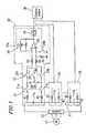
- Figure 1 is a circuit diagram illustrating an example of a voltage detection apparatus according to an embodiment of the present invention.
- Figure 2 is a timing chart describing an operation of the voltage detection apparatus according to an embodiment of the present invention.
- Figure 3 is a circuit diagram illustrating an example of a voltage detection apparatus according to another embodiment of the present invention.
- Embodiments of the present invention will now be described with reference to the accompanying drawings.
- Figure 1 is a circuit diagram illustrating an example of a
voltage detection apparatus 20 according to an embodiment of the present invention. Thevoltage detection apparatus 20 is used for detecting a voltage of abattery power supply 11 used as a power source for an electric motor of a hybrid vehicle which incorporates the electric motor and a combustion engine together as a driving source thereof. In thebattery power supply 11, for example, twenty fourbattery units 11a (three shown in Figure 1 for simplicity), each including a prescribed number (e.g., 10) of batteries (nickel metal hydride storage batteries) in a series connection. One or morevoltage detection apparatuses 20 are used for detecting the voltages of therespective battery units 11a. - An output from the
battery power supply 11 is supplied to a three-phase motor 13 via aninverter 12. The rotating operation of themotor 13 provides a driving force to the vehicle. - Each of the
voltage detection apparatuses 20 has a pair ofcapacitors first switch 21. Hereinafter, thecapacitors first switch 21 includes a pair of normally-open contacts open contact 21a of thefirst switch 21 is inserted between a resistance 41 coupled to a positive electrode of thebattery unit 11a and one terminal of a series circuit composed of thefirst capacitor 28 and thesecond capacitor 29. The normally-open contact 21b of thefirst switch 21 is inserted between aresistance 42 coupled to a negative electrode of the battery unit lla and another terminal of the series circuit composed of thefirst capacitor 28 and thesecond capacitor 29. - A node between the
first capacitor 28 and thesecond capacitor 29 can be body-grounded via asecond switch 22. In other words, the node between thefirst capacitor 28 and thesecond capacitor 29 has a potential equal to that of the body ground when thesecond switch 22 is turned on. As described above, thesecond switch 22 functions as adjusting means for the potential of the node between thefirst capacitor 28 and thesecond capacitor 29. - A voltage across the first and
second capacitors third switch 23. Thethird switch 23 includes a pair of normally-open contacts open contact 23a of thethird switch 23 is inserted between thefirst capacitor 28 and aresistance 43 coupled to a negative terminal of thedifferential amplifier 25. The normally-open contact 23b of thethird switch 23 is inserted between thesecond capacitor 29 and aresistance 44 coupled to a positive terminal of thedifferential amplifier 25. - Input voltages to the negative terminal and the positive terminal of the
differential amplifier 25 can be respectively fixed by an interlocking pair of normally-open contacts fourth switch 24. The normally-open contact 24a of thefourth switch 24 is inserted between the negative terminal of thedifferential amplifier 25 and an output terminal of thedifferential amplifier 25. A resistance 46 is provided in parallel connection with the normally-open contact 24a. The normally-open contact 24b of thefourth switch 24 is inserted between the positive terminal of thedifferential amplifier 25 and the body ground. Aresistance 45 is provided in parallel connection with the normally-open contact 24b. - An output from the
differential amplifier 25 is supplied to an A/D converter 26. An output from the A/D converter 26 is supplied to a control device (CPU) 30 as an output from the entirevoltage detection apparatus 20. - Now, operation of the
voltage detection apparatus 20 having the above-described structure for detecting a voltage of each of thebattery units 11a of thebattery power supply 11 will be described based on a timing chart shown in Figure 2. When detecting a voltage of abattery unit 11a, all of the first through fourth switches 21-24 are placed in an off-state (non-conducting state). Then, firstly, thefirst switch 21 is turned on (conducting) so that normally-open contacts battery unit 11a to be applied to the first andsecond capacitors second capacitors - After the
first switch 21 has been kept ON for a prescribed period of time, thefirst switch 21 is turned OFF so that the normally-open contacts capacitors - After the
first switch 21 is turned OFF, thesecond switch 22 and thefourth switch 24 are turned ON after a lapse of a prescribed period of time. In this case, it is preferable that thesecond switch 22 and thefourth switch 24 are turned on simultaneously, but they may be turned on at separate times. When thesecond switch 22 is turned on, the node between thefirst capacitor 28 and thesecond capacitor 29 is body-grounded and a potential of the node between thecapacitors capacitor 29 may be equal to or less than that of the body ground. Moreover, when thefourth switch 24 is turned on so that each of the normally-open contacts differential amplifier 25 is fixed to a potential equal to that of the output node of the differential amplifier 25 (0 V), and the potential of the positive terminal thereof is fixed to the body ground potential (0 V). The potential of the node between thecapacitors differential amplifier 25 at this point, serves as a reference potential of thedifferential amplifier 25. - After a lapse of a prescribed period of time since the
second switch 22 and thefourth switch 24 are turned on, thethird switch 23 is turned on so that the normally-open contacts second capacitors differential amplifier 25. Since thefourth switch 24 is in an on-state, the voltage of each terminal of thedifferential amplifier 25 is fixed. Therefore, the voltage across the first andsecond capacitors differential amplifier 25. - After a lapse of a prescribed period of time since the
third switch 23 is turned on, thefourth switch 24 is turned off. As a result, the voltage of each terminal of thedifferential amplifier 25 is no longer fixed, so that a voltage corresponding to the electric charge stored in the first andsecond capacitors differential amplifier 25. - In this case, the voltage of each of the
capacitors differential amplifier 25, while the voltage of each input terminal of thedifferential amplifier 25 is fixed to 0 V. Therefore, it is ensured that the voltage of each input terminal will be kept within a tolerable range. Accordingly, an output from thedifferential amplifier 25 is prevented from being saturated, and the voltage applied from each of thecapacitors differential amplifier 25 will be kept within a tolerable range, deterioration and breakdown of thedifferential amplifier 25 can be prevented. - As described above, after an electric charge corresponding to the voltage of the
battery unit 11a is accumulated in thefirst capacitor 28 and thesecond capacitor 29, a stabilized voltage across thefirst capacitor 28 and thesecond capacitor 29 is applied to thedifferential amplifier 25, so that thedifferential amplifier 25 can stably detect the voltage across thecapacitors - The
differential amplifier 25 outputs to the A/D converter 26 a signal corresponding to the voltage applied from thecapacitors D converter 26 converts the output from thedifferential amplifier 25 to a digital signal and outputs the resultant signal to thecontrol device 30. Thecontrol device 30 determines whether the voltage of the battery unit lla as detected by thevoltage detection apparatus 20 has a normal value based on the digital signal output from the A/D converter 26. - As described above, the voltage of each
battery unit 11a is separately detected by the respectivevoltage detection apparatus 20, whereby it can be determined whether the voltage of eachbattery unit 11a is normal. - Figure 3 illustrates a voltage detection apparatus 20' according to an embodiment of the present invention. The structure of the voltage detection apparatus 20' is the same as that of the voltage detection apparatus 20 (Figure 1) except that the
capacitor 29, the normally-open contact 23b and theresistance 44 are omitted. Operating procedures are essentially the same as those of thevoltage detection apparatus 20. Only onecapacitor 28 is provided in the voltage detection apparatus 20' as a capacitor to which a voltage of the battery unit lla is applied, whereby the structure of the voltage detection apparatus 20' can be simplified. - In each of the above-described embodiments of the invention, as each of the first through third switches 21-23 (but not the
fourth switch 24 used for stabilizing the voltage of each input terminal of the differential amplifier 25), a transistor such as an FET (field-effect transistor) or an SSR (solid-state relay) incorporating such a transistor so as to have a high voltage breakdown value, e.g., 400 V, may be used. Thedifferential amplifier 25 used herein may be of any type commonly used in the art. - Moreover, the voltage detection apparatus may be structured so that the on/off timing of each of the switches 21-24 is controlled by the
control device 30 or another control device. - The above-described embodiments have a structure in which the
voltage detection apparatus 20 or 20' is provided corresponding to eachbattery unit 11a, but the present invention is not limited to such a structure. For example, only onevoltage detection apparatus 20 or 20' may be used so as to be selectively coupled to each of thebattery units 11a in turn. - Moreover, three or more capacitors may be provided for accumulating therein an electric charge corresponding to a voltage of a
battery unit 11a. In this case, at least one preselected capacitor may be body-grounded via thesecond switch 22 while the other capacitors may be electrically coupled to thesecond switch 22 via the preselected capacitor. - Moreover, the present invention is operable even if the
fourth switch 24 is omitted from thevoltage detection apparatus 20 or 20'. However, it is more preferable that thevoltage detection apparatus 20 or 20' includes thefourth switch 24. - Moreover, the A/
D converter 26 may be provided externally to thevoltage detection apparatus 20 or 20'. - The present invention provides an apparatus and a method for detecting a voltage which is capable of accurately measuring a voltage of a battery, where a differential amplifier is used to detect a voltage across a capacitor(s) to which a voltage of the battery is applied, the voltage across the capacitor(s) being stabilized in the manner described above. Moreover, a voltage of each input terminal of the differential amplifier is fixed to a prescribed voltage value so that the voltage applied by each capacitor to the differential amplifier is stabilized. Therefore, the voltage of a battery can be detected more accurately.
- Various other modifications will be apparent to and can be readily made by those skilled in the art without departing from the scope and spirit of this invention. Accordingly, it is not intended that the scope of the claims appended hereto be limited to the description as set forth herein, but rather that the claims be broadly construed.
Claims (13)
- A voltage detection apparatus for detecting a voltage of at least one battery, comprising:capacitor means to which a voltage is applied from the at least one battery and in which an electric charge accumulates;adjustment means for adjusting potentials at both ends of the capacitor means such that a potential difference between a potential at one end of the capacitor means and a reference potential is less than a potential difference between a potential at one end of the at least one battery and the reference potential, and that a potential difference between a potential at another end of the capacitor means and the reference potential is less than a potential difference between a potential at another end of the at least one battery and the reference potential; andvoltage detection means for detecting a voltage of the at least one battery based on a potential difference between the one end of the capacitor means and the other end of the capacitor means after the potentials of both ends of the capacitor means have been adjusted by the adjustment means.
- A voltage detection apparatus according to claim 1, wherein the capacitor means comprises a plurality of capacitors in a series connection.
- A voltage detection apparatus according to claim 1, wherein:the capacitor means is electrically connected with the at least one battery via a first switching means;the adjustment means comprises a second switching means for switching a state of the capacitor means so as to be electrically coupled or decoupled to or from a prescribed potential; andthe voltage detection means is electrically coupled to the capacitor means via a third switching means.
- A voltage detection apparatus according to claim 3, wherein the capacitor means is electrically coupled to the prescribed potential via the second switching means and the potentials at both ends of the capacitor means are adjusted.
- A voltage detection apparatus according to claim 1, wherein a potential difference between the one end of the at least one battery and the other end of the at least one battery is equal to the potential difference between the one end of the capacitor means and the other end of the capacitor means.
- A voltage detection apparatus according to claim 3, wherein the capacitor means comprises a plurality of capacitors in a series connection and at least one node between the plurality of capacitors is coupled to the prescribed potential via the second switching means.
- A voltage detection apparatus according to claim 3, further comprising a fourth switching means for switching a state of a first input terminal of the voltage detection means so as to be electrically coupled or decoupled to or from the reference potential.
- A voltage detection apparatus according to claim 7, wherein the first input terminal is electrically coupled to the reference potential via the fourth switching means and a potential of the first input terminal is equal to the reference potential.
- A voltage detection apparatus according to claim 1, further comprising conversion means for converting an analog signal from the voltage detection means to a digital signal.
- A voltage detection apparatus according to claim 1, wherein the voltage detection means is a differential amplifier.
- A method for detecting a voltage of at least one battery by means of the voltage detection apparatus according to claim 3, comprising the steps of:electrically coupling the at least one battery to the capacitor means via the first switching means so as to allow an electric charge to accumulate in the capacitor means;electrically isolating the at least one battery and the capacitor means from each other after the electric charge is accumulated in the capacitor means;electrically coupling the capacitor means to the reference potential via the second switching means, thereby adjusting the potentials at both ends of the capacitor means;electrically coupling the capacitor means to the voltage detection means via the third switching means; anddetecting the potential difference between the one end of the capacitor means and the other end of the capacitor means by means of the voltage detection means.
- A method according to claim 11, wherein the voltage detection apparatus includes a fourth switching means for switching a state of a first input terminal of the voltage detection means so as to be electrically coupled or decoupled to or from the reference potential, the method further comprising the steps of:electrically coupling the first input terminal to the reference potential via the fourth switching means; andswitching a state of the first input terminal so as not to be electrically coupled to the reference potential via the fourth switching means after the step of electrically coupling the capacitor means to the voltage detection means.
- A method according to claim 12, wherein the step of adjusting the potentials at both ends of the capacitor means and the step of electrically coupling the first input terminal to the reference potential are performed simultaneously.
Applications Claiming Priority (2)
| Application Number | Priority Date | Filing Date | Title |
|---|---|---|---|
| JP2000009554A JP4472820B2 (en) | 2000-01-18 | 2000-01-18 | Battery voltage detection device and detection method |
| JP2000009554 | 2000-01-18 |
Publications (3)
| Publication Number | Publication Date |
|---|---|
| EP1118869A1 true EP1118869A1 (en) | 2001-07-25 |
| EP1118869B1 EP1118869B1 (en) | 2008-10-08 |
| EP1118869B8 EP1118869B8 (en) | 2008-12-31 |
Family
ID=18537691
Family Applications (1)
| Application Number | Title | Priority Date | Filing Date |
|---|---|---|---|
| EP01100154A Expired - Lifetime EP1118869B8 (en) | 2000-01-18 | 2001-01-16 | Battery voltage detection apparatus and detection method |
Country Status (4)
| Country | Link |
|---|---|
| US (1) | US6462550B2 (en) |
| EP (1) | EP1118869B8 (en) |
| JP (1) | JP4472820B2 (en) |
| DE (1) | DE60136020D1 (en) |
Cited By (1)
| Publication number | Priority date | Publication date | Assignee | Title |
|---|---|---|---|---|
| DE102007052929A1 (en) * | 2007-11-07 | 2009-05-20 | Braun Gmbh | Circuit arrangement with a battery cascade |
Families Citing this family (16)
| Publication number | Priority date | Publication date | Assignee | Title |
|---|---|---|---|---|
| JP4662098B2 (en) * | 2001-03-27 | 2011-03-30 | 株式会社デンソー | Flying capacitor type assembled battery voltage detector |
| US20030175451A1 (en) * | 2002-03-12 | 2003-09-18 | Palitha Wickramanayake | Chemically-bonded porous coatings that enhance humid fastness and fade fastness performance of ink jet images |
| KR101038204B1 (en) * | 2004-02-25 | 2011-05-31 | 주성엔지니어링(주) | Antenna for plasma |
| US7521896B2 (en) * | 2004-07-20 | 2009-04-21 | Panasonic Ev Energy Co., Ltd. | Abnormal voltage detector apparatus for detecting voltage abnormality in assembled battery |
| JP4905300B2 (en) * | 2006-09-28 | 2012-03-28 | トヨタ自動車株式会社 | Power supply system, vehicle equipped with the same, control method for power supply system, and computer-readable recording medium recording a program for causing a computer to execute the control method |
| JP4881819B2 (en) * | 2007-09-07 | 2012-02-22 | オンセミコンダクター・トレーディング・リミテッド | Battery voltage detection circuit |
| JP5022925B2 (en) * | 2008-01-23 | 2012-09-12 | オンセミコンダクター・トレーディング・リミテッド | Battery voltage detection circuit |
| US8384354B2 (en) | 2009-10-15 | 2013-02-26 | GM Global Technology Operations LLC | Sensor arrangement and method of using the same |
| US8723482B2 (en) * | 2010-11-04 | 2014-05-13 | Elite Power Solutions Llc | Battery unit balancing system |
| JP5718067B2 (en) * | 2011-01-17 | 2015-05-13 | ラピスセミコンダクタ株式会社 | Boosting system, diagnostic method, and diagnostic program |
| EP2802891B1 (en) | 2012-01-12 | 2020-03-04 | Allison Transmission, Inc. | System and method for high voltage cable detection in hybrid vehicles |
| CA2863605C (en) | 2012-02-17 | 2021-01-12 | Allison Transmission, Inc. | High voltage cable detection using rotating machine in hybrid vehicles |
| JP6376722B2 (en) | 2013-02-15 | 2018-08-22 | エイブリック株式会社 | Battery voltage detection circuit |
| US9347998B2 (en) * | 2013-04-17 | 2016-05-24 | Allegro Microsystems, Llc | System and method for measuring battery voltage |
| JP6621256B2 (en) * | 2015-07-16 | 2019-12-18 | ラピスセミコンダクタ株式会社 | Semiconductor device, battery monitoring device, and battery cell voltage detection method |
| US11650656B1 (en) | 2022-04-20 | 2023-05-16 | Hong Kong Applied Science and Technology Research Institute Company Limited | Low-power voltage detector for low-voltage CMOS processes |
Citations (4)
| Publication number | Priority date | Publication date | Assignee | Title |
|---|---|---|---|---|
| US4590430A (en) * | 1982-12-13 | 1986-05-20 | Electricite De France (Service National) | Apparatus for monitoring cell capacity in a storage battery |
| EP0432640A2 (en) * | 1989-12-12 | 1991-06-19 | Fraunhofer-Gesellschaft Zur Förderung Der Angewandten Forschung E.V. | Monitoring device for accumulators |
| DE19618897A1 (en) * | 1996-05-10 | 1997-11-13 | Varta Batterie | Circuit for determining insulation resistance of accumulator battery in sole use |
| JP2000014027A (en) * | 1998-06-23 | 2000-01-14 | Hitachi Ltd | Control device for capacitor |
Family Cites Families (2)
| Publication number | Priority date | Publication date | Assignee | Title |
|---|---|---|---|---|
| US5281920A (en) * | 1992-08-21 | 1994-01-25 | Btech, Inc. | On-line battery impedance measurement |
| US5646534A (en) * | 1995-01-06 | 1997-07-08 | Chrysler Corporation | Battery monitor for electric vehicles |
-
2000
- 2000-01-18 JP JP2000009554A patent/JP4472820B2/en not_active Expired - Lifetime
-
2001
- 2001-01-16 EP EP01100154A patent/EP1118869B8/en not_active Expired - Lifetime
- 2001-01-16 DE DE60136020T patent/DE60136020D1/en not_active Expired - Lifetime
- 2001-01-18 US US09/765,482 patent/US6462550B2/en not_active Expired - Lifetime
Patent Citations (4)
| Publication number | Priority date | Publication date | Assignee | Title |
|---|---|---|---|---|
| US4590430A (en) * | 1982-12-13 | 1986-05-20 | Electricite De France (Service National) | Apparatus for monitoring cell capacity in a storage battery |
| EP0432640A2 (en) * | 1989-12-12 | 1991-06-19 | Fraunhofer-Gesellschaft Zur Förderung Der Angewandten Forschung E.V. | Monitoring device for accumulators |
| DE19618897A1 (en) * | 1996-05-10 | 1997-11-13 | Varta Batterie | Circuit for determining insulation resistance of accumulator battery in sole use |
| JP2000014027A (en) * | 1998-06-23 | 2000-01-14 | Hitachi Ltd | Control device for capacitor |
Non-Patent Citations (1)
| Title |
|---|
| PATENT ABSTRACTS OF JAPAN vol. 2000, no. 04 31 August 2000 (2000-08-31) * |
Cited By (1)
| Publication number | Priority date | Publication date | Assignee | Title |
|---|---|---|---|---|
| DE102007052929A1 (en) * | 2007-11-07 | 2009-05-20 | Braun Gmbh | Circuit arrangement with a battery cascade |
Also Published As
| Publication number | Publication date |
|---|---|
| JP4472820B2 (en) | 2010-06-02 |
| US6462550B2 (en) | 2002-10-08 |
| EP1118869B8 (en) | 2008-12-31 |
| EP1118869B1 (en) | 2008-10-08 |
| US20010019269A1 (en) | 2001-09-06 |
| DE60136020D1 (en) | 2008-11-20 |
| JP2001201548A (en) | 2001-07-27 |
Similar Documents
| Publication | Publication Date | Title |
|---|---|---|
| US6462550B2 (en) | Battery voltage detection apparatus and detection method | |
| US6570387B2 (en) | Multiplex voltage measurement apparatus | |
| JP3518318B2 (en) | Stacked voltage measurement device | |
| US6462510B1 (en) | Battery voltage detector | |
| US7471064B2 (en) | Circuit system for a battery electronic control unit | |
| US6621273B2 (en) | Voltage measurement apparatus | |
| US7759903B2 (en) | Battery voltage measurement circuit, battery voltage measurement method, and battery electric control unit | |
| JP3672183B2 (en) | Battery voltage detector | |
| EP1146345B1 (en) | Multiplex voltage measurement apparatus | |
| JP4974593B2 (en) | Power supply for vehicle | |
| US20110031812A1 (en) | Voltage detection device and power supply system using same | |
| KR20060119780A (en) | Apparatus and method for detecting voltage of assembled battery | |
| US7023178B2 (en) | Voltage measuring apparatus | |
| JP5092812B2 (en) | Battery monitoring device and failure diagnosis method | |
| JP2003114243A (en) | Battery pack voltage detection circuit | |
| JPH11113182A (en) | Instrument for measuring voltage of battery | |
| US20030052688A1 (en) | Battery voltage detection device | |
| CN114746762A (en) | Electric leakage detection device and power supply system for vehicle | |
| CN111077472A (en) | Electric leakage judging system | |
| CN111971564A (en) | Voltage detection circuit for vehicle | |
| JPH04125033A (en) | Two-voltage battery |
Legal Events
| Date | Code | Title | Description |
|---|---|---|---|
| PUAI | Public reference made under article 153(3) epc to a published international application that has entered the european phase |
Free format text: ORIGINAL CODE: 0009012 |
|
| AK | Designated contracting states |
Kind code of ref document: A1 Designated state(s): DE FR GB |
|
| AX | Request for extension of the european patent |
Free format text: AL;LT;LV;MK;RO;SI |
|
| 17P | Request for examination filed |
Effective date: 20010615 |
|
| AKX | Designation fees paid |
Free format text: DE FR GB |
|
| 17Q | First examination report despatched |
Effective date: 20040811 |
|
| 17Q | First examination report despatched |
Effective date: 20040811 |
|
| GRAP | Despatch of communication of intention to grant a patent |
Free format text: ORIGINAL CODE: EPIDOSNIGR1 |
|
| GRAS | Grant fee paid |
Free format text: ORIGINAL CODE: EPIDOSNIGR3 |
|
| GRAA | (expected) grant |
Free format text: ORIGINAL CODE: 0009210 |
|
| AK | Designated contracting states |
Kind code of ref document: B1 Designated state(s): DE FR GB |
|
| REG | Reference to a national code |
Ref country code: GB Ref legal event code: FG4D |
|
| RAP2 | Party data changed (patent owner data changed or rights of a patent transferred) |
Owner name: TOYOTA JIDOSHA KABUSHIKI KAISHA Owner name: PANASONIC CORPORATION |
|
| REF | Corresponds to: |
Ref document number: 60136020 Country of ref document: DE Date of ref document: 20081120 Kind code of ref document: P |
|
| PLBE | No opposition filed within time limit |
Free format text: ORIGINAL CODE: 0009261 |
|
| STAA | Information on the status of an ep patent application or granted ep patent |
Free format text: STATUS: NO OPPOSITION FILED WITHIN TIME LIMIT |
|
| 26N | No opposition filed |
Effective date: 20090709 |
|
| REG | Reference to a national code |
Ref country code: FR Ref legal event code: PLFP Year of fee payment: 16 |
|
| REG | Reference to a national code |
Ref country code: FR Ref legal event code: PLFP Year of fee payment: 17 |
|
| REG | Reference to a national code |
Ref country code: FR Ref legal event code: PLFP Year of fee payment: 18 |
|
| PGFP | Annual fee paid to national office [announced via postgrant information from national office to epo] |
Ref country code: FR Payment date: 20191216 Year of fee payment: 20 |
|
| PGFP | Annual fee paid to national office [announced via postgrant information from national office to epo] |
Ref country code: DE Payment date: 20191231 Year of fee payment: 20 Ref country code: GB Payment date: 20200113 Year of fee payment: 20 |
|
| REG | Reference to a national code |
Ref country code: DE Ref legal event code: R071 Ref document number: 60136020 Country of ref document: DE |
|
| REG | Reference to a national code |
Ref country code: GB Ref legal event code: PE20 Expiry date: 20210115 |
|
| PG25 | Lapsed in a contracting state [announced via postgrant information from national office to epo] |
Ref country code: GB Free format text: LAPSE BECAUSE OF EXPIRATION OF PROTECTION Effective date: 20210115 |