EP1119425B1 - Can end having a strengthened side wall and apparatus and method of making same - Google Patents
Can end having a strengthened side wall and apparatus and method of making same Download PDFInfo
- Publication number
- EP1119425B1 EP1119425B1 EP99943775A EP99943775A EP1119425B1 EP 1119425 B1 EP1119425 B1 EP 1119425B1 EP 99943775 A EP99943775 A EP 99943775A EP 99943775 A EP99943775 A EP 99943775A EP 1119425 B1 EP1119425 B1 EP 1119425B1
- Authority
- EP
- European Patent Office
- Prior art keywords
- side wall
- chuck
- angle
- wall
- seaming
- Prior art date
- Legal status (The legal status is an assumption and is not a legal conclusion. Google has not performed a legal analysis and makes no representation as to the accuracy of the status listed.)
- Expired - Lifetime
Links
Images

Classifications
-
- B—PERFORMING OPERATIONS; TRANSPORTING
- B65—CONVEYING; PACKING; STORING; HANDLING THIN OR FILAMENTARY MATERIAL
- B65D—CONTAINERS FOR STORAGE OR TRANSPORT OF ARTICLES OR MATERIALS, e.g. BAGS, BARRELS, BOTTLES, BOXES, CANS, CARTONS, CRATES, DRUMS, JARS, TANKS, HOPPERS, FORWARDING CONTAINERS; ACCESSORIES, CLOSURES, OR FITTINGS THEREFOR; PACKAGING ELEMENTS; PACKAGES
- B65D7/00—Containers having bodies formed by interconnecting or uniting two or more rigid, or substantially rigid, components made wholly or mainly of metal
- B65D7/12—Containers having bodies formed by interconnecting or uniting two or more rigid, or substantially rigid, components made wholly or mainly of metal characterised by wall construction or by connections between walls
- B65D7/34—Containers having bodies formed by interconnecting or uniting two or more rigid, or substantially rigid, components made wholly or mainly of metal characterised by wall construction or by connections between walls with permanent connections between walls
- B65D7/36—Containers having bodies formed by interconnecting or uniting two or more rigid, or substantially rigid, components made wholly or mainly of metal characterised by wall construction or by connections between walls with permanent connections between walls formed by rolling, or by rolling and pressing
-
- B—PERFORMING OPERATIONS; TRANSPORTING
- B21—MECHANICAL METAL-WORKING WITHOUT ESSENTIALLY REMOVING MATERIAL; PUNCHING METAL
- B21D—WORKING OR PROCESSING OF SHEET METAL OR METAL TUBES, RODS OR PROFILES WITHOUT ESSENTIALLY REMOVING MATERIAL; PUNCHING METAL
- B21D51/00—Making hollow objects
- B21D51/16—Making hollow objects characterised by the use of the objects
- B21D51/38—Making inlet or outlet arrangements of cans, tins, baths, bottles, or other vessels; Making can ends; Making closures
-
- Y—GENERAL TAGGING OF NEW TECHNOLOGICAL DEVELOPMENTS; GENERAL TAGGING OF CROSS-SECTIONAL TECHNOLOGIES SPANNING OVER SEVERAL SECTIONS OF THE IPC; TECHNICAL SUBJECTS COVERED BY FORMER USPC CROSS-REFERENCE ART COLLECTIONS [XRACs] AND DIGESTS
- Y10—TECHNICAL SUBJECTS COVERED BY FORMER USPC
- Y10T—TECHNICAL SUBJECTS COVERED BY FORMER US CLASSIFICATION
- Y10T29/00—Metal working
- Y10T29/53—Means to assemble or disassemble
- Y10T29/53709—Overedge assembling means
Abstract
Description
Claims (12)
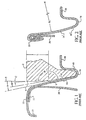
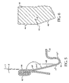
- A method of seaming a can end (10) to a can body (20), said can body (10) defining a central axis thereof, comprising the steps of:a) forming a can end (10) having a side wall (14) and a peripheral seaming panel (13), said side wall (14) formed by a single straight section disposed at an angle A with respect to said central axis that is within the range of 12° to 15°;b) inserting a chuck (42) into said can end adjacent said side wall, said chuck having upper and lower portions (44, 46) forming upper and lower chuck walls, said lower chuck wall (46) being frustoconical and disposed at an angle B with respect to said central axis that is no less than said angle A at which said straight section of said can end side wall is disposed, said upper chuck wall (44) disposed at an angle C with respect to said central axis that is within the range of 0° to -2°; andc) seaming said seaming panel (13) of said can end to a can body so as to reshape said can end side wall into a segmented side wall comprised of upper and lower straight sections (66, 68), said upper and lower straight sections intersecting at an obtuse angle F.
- The method according to claim 1, wherein said obtuse angle F at which said straight sections of can end side wall intersect is within the range of 165° to 170°.
- The method according to claim 1 or claim 2, wherein said seaming step comprises reshaping said can end side wall so as to form a circumferentially extending crease (69) separating said upper and lower straight sections.
- The method according to any one of claims 1 to 3, wherein said upper and lower chuck walls intersect at an edge (45) forming a radius in the range of about 0.001 to 0.020 inch (0.0254 to 0.508 mm).
- The method according to any one of claims 1 to 4, wherein said can end further comprises a circular bead (16), said side wall of said can end extending between said circular bead and said peripheral seaming panel.
- The method according to any one of claims 1 to 5, wherein said upper and lower chuck walls intersect at an edge (45), and wherein the step of inserting said chuck into said can end adjacent said can end side wall comprises inserting said chuck so that there is essentially no gap between said chuck wall edge and said can end side wall.
- The method according to any one of claims 1 to 6, wherein the step of inserting said chuck into said can end adjacent said can end side wall comprises inserting said chuck so that there is an interference between said chuck wall edge and said can end side wall.
- A chuck (42) for use in seaming a can end (10) to a can body (20), said chuck defining a central axis thereof, said can end having a side wall disposed at an angle A with respect to said central axis in the range of 12° to 15°, comprising:a) an upper portion forming an upper wall (44), said upper wall being disposed at an angle C with respect to said central axis that is within the range of 0° to -2°; andb) a lower portion forming a lower wall (46), said lower wall being frustoconical and disposed at an angle D' with respect to said upper wall that is within the range of 162° to 168° and being disposed at an angle B' with respect to said central axis that is not greater than 16°.
- The chuck according to claim 8, wherein said upper and lower chuck walls intersect at an edge (45), said edge forming a radius in the range of about 0.001 to 0.020 inch (0.0254 to 0.508 mm).
- A can comprising:a) a can body (20) defining a central axis thereof; andb) a can end (10"), said can end (10") having a peripheral edge forming a seam (62) in conjunction with said can body that attaches said can end to said can body, said can end having a side wall (14"); characterised in that the side wall is formed by upper and lower straight sections (66, 68), said lower straight section (68) being frustoconical and disposed at an angle A with respect to said central axis that is in the range of 12° to 15°, said upper and lower straight sections intersecting at an obtuse angle F so as to form a circumferentially extending crease (69) separating said upper and lower straight sections.
- The can according to claim 11, wherein said obtuse angle F is within the range of 165° to 170°.
- The can according to claim 10 or claim 11, wherein said can end further comprises a circumferentially extending bead (16), said side wall of said can end extending between said seam and said bead, said upper straight section of said side wall extending between said seam and said crease, said lower straight section of said side wall extending between said crease and said bead.
Applications Claiming Priority (3)
| Application Number | Priority Date | Filing Date | Title |
|---|---|---|---|
| US140722 | 1993-10-21 | ||
| US09/140,722 US6102243A (en) | 1998-08-26 | 1998-08-26 | Can end having a strengthened side wall and apparatus and method of making same |
| PCT/US1999/018944 WO2000012243A2 (en) | 1998-08-26 | 1999-08-19 | Can end having a strengthened side wall and apparatus and method of making same |
Publications (2)
| Publication Number | Publication Date |
|---|---|
| EP1119425A2 EP1119425A2 (en) | 2001-08-01 |
| EP1119425B1 true EP1119425B1 (en) | 2003-09-17 |
Family
ID=22492521
Family Applications (1)
| Application Number | Title | Priority Date | Filing Date |
|---|---|---|---|
| EP99943775A Expired - Lifetime EP1119425B1 (en) | 1998-08-26 | 1999-08-19 | Can end having a strengthened side wall and apparatus and method of making same |
Country Status (14)
| Country | Link |
|---|---|
| US (2) | US6102243A (en) |
| EP (1) | EP1119425B1 (en) |
| JP (2) | JP5021859B2 (en) |
| CN (1) | CN1170642C (en) |
| AT (1) | ATE249899T1 (en) |
| AU (1) | AU748316B2 (en) |
| BR (1) | BR9913252A (en) |
| CA (1) | CA2341197C (en) |
| DE (1) | DE69911443T2 (en) |
| DK (1) | DK1119425T3 (en) |
| ES (1) | ES2204151T3 (en) |
| PL (1) | PL190341B1 (en) |
| PT (1) | PT1119425E (en) |
| WO (1) | WO2000012243A2 (en) |
Families Citing this family (39)
| Publication number | Priority date | Publication date | Assignee | Title |
|---|---|---|---|---|
| US20130221013A1 (en) * | 1997-04-07 | 2013-08-29 | J. Bruce Kolowich | Thermal receptacle with phase change material |
| US7380684B2 (en) | 1999-12-08 | 2008-06-03 | Metal Container Corporation | Can lid closure |
| CA2472295C (en) * | 1999-12-08 | 2011-11-29 | Tuan A. Nguyen | Metallic beverage can end with improved chuck wall and countersink |
| US6561004B1 (en) * | 1999-12-08 | 2003-05-13 | Metal Container Corporation | Can lid closure and method of joining a can lid closure to a can body |
| US8490825B2 (en) | 1999-12-08 | 2013-07-23 | Metal Container Corporation | Can lid closure and method of joining a can lid closure to a can body |
| US6460723B2 (en) | 2001-01-19 | 2002-10-08 | Ball Corporation | Metallic beverage can end |
| BR0207838A (en) * | 2001-02-26 | 2004-06-22 | Ball Corp | Beverage can edge with projected reinforcement fillet |
| US6419110B1 (en) | 2001-07-03 | 2002-07-16 | Container Development, Ltd. | Double-seamed can end and method for forming |
| US7819275B2 (en) * | 2001-07-03 | 2010-10-26 | Container Development, Ltd. | Can shell and double-seamed can end |
| MXPA03012003A (en) * | 2001-07-03 | 2005-07-01 | Container Dev Ltd | Can shell and double-seamed can end. |
| US7341163B2 (en) * | 2001-07-03 | 2008-03-11 | Container Development, Ltd. | Can shell and double-seamed can end |
| ES2259094T3 (en) * | 2001-11-05 | 2006-09-16 | Corus Staal Bv | SUPERIOR CONE FOR A CAN OF AEROSOL, AND A CAN OF AEROSOL PROVIDED WITH THE SAME. |
| US6761280B2 (en) | 2001-12-27 | 2004-07-13 | Alcon Inc. | Metal end shell and easy opening can end for beer and beverage cans |
| US7591392B2 (en) | 2002-04-22 | 2009-09-22 | Crown Packaging Technology, Inc. | Can end |
| US6736283B1 (en) | 2002-11-19 | 2004-05-18 | Alcoa Inc. | Can end, tooling for manufacture of the can end and seaming chuck adapted to affix a converted can end to a can body |
| US6915553B2 (en) * | 2003-02-19 | 2005-07-12 | Rexam Beverage Can Company | Seaming apparatus and method for cans |
| US20060071005A1 (en) | 2004-09-27 | 2006-04-06 | Bulso Joseph D | Container end closure with improved chuck wall and countersink |
| US7506779B2 (en) | 2005-07-01 | 2009-03-24 | Ball Corporation | Method and apparatus for forming a reinforcing bead in a container end closure |
| CN100457561C (en) * | 2006-05-27 | 2009-02-04 | 苏州斯莱克精密设备有限公司 | Anti-atmospheric pressure type metal pop-torp cover |
| JP5208029B2 (en) * | 2009-03-17 | 2013-06-12 | ユニバーサル製缶株式会社 | Can winding device and can winding method |
| JP2011189986A (en) * | 2010-02-17 | 2011-09-29 | Toyo Seikan Kaisha Ltd | Can lid |
| JP5484252B2 (en) * | 2010-08-10 | 2014-05-07 | ユニバーサル製缶株式会社 | Can winding device |
| CN101966887A (en) * | 2010-08-10 | 2011-02-09 | 无锡市四方制桶有限公司 | Pre-rolling free bottom cap of steel drum |
| JP5484273B2 (en) * | 2010-09-07 | 2014-05-07 | ユニバーサル製缶株式会社 | Can winding device |
| JP5452435B2 (en) * | 2010-09-21 | 2014-03-26 | ユニバーサル製缶株式会社 | Can winding method and can winding device |
| US9550604B2 (en) | 2010-10-18 | 2017-01-24 | Silgan Containers Llc | Can end with strengthening bead configuration |
| USD653109S1 (en) | 2010-10-18 | 2012-01-31 | Stolle Machinery Company, Llc | Can end |
| US8727169B2 (en) | 2010-11-18 | 2014-05-20 | Ball Corporation | Metallic beverage can end closure with offset countersink |
| US8939695B2 (en) | 2011-06-16 | 2015-01-27 | Sonoco Development, Inc. | Method for applying a metal end to a container body |
| US8998027B2 (en) | 2011-09-02 | 2015-04-07 | Sonoco Development, Inc. | Retort container with thermally fused double-seamed or crimp-seamed metal end |
| US10131455B2 (en) | 2011-10-28 | 2018-11-20 | Sonoco Development, Inc. | Apparatus and method for induction sealing of conveyed workpieces |
| US10399139B2 (en) | 2012-04-12 | 2019-09-03 | Sonoco Development, Inc. | Method of making a retort container |
| CN103057789A (en) * | 2012-11-20 | 2013-04-24 | 东莞市精丽制罐有限公司 | Box body aluminum bottom rolling and sealing structure of food box and secondary stamping buckle lock-bottom rolling and sealing manufacturing method thereof |
| US9181007B2 (en) | 2013-03-12 | 2015-11-10 | Rexam Beverage Can Company | Beverage can end with vent port |
| US9181015B2 (en) | 2013-03-15 | 2015-11-10 | Raymond Booska | Thermal receptacle with phase change material |
| US11206938B2 (en) | 2013-03-15 | 2021-12-28 | Raymond Booska | Thermal receptacle with phase change material |
| JP2014094411A (en) * | 2013-12-27 | 2014-05-22 | Universal Seikan Kk | Can winding-fastening part structure |
| US10894630B2 (en) * | 2017-08-30 | 2021-01-19 | Stolle Machinery Company, Llc | Pressure can end compatible with standard can seamer |
| KR102394443B1 (en) * | 2020-09-21 | 2022-05-03 | 이정열 | Can Seaming apparatus having multifunctiona seaming chuck |
Family Cites Families (109)
| Publication number | Priority date | Publication date | Assignee | Title |
|---|---|---|---|---|
| US2346165A (en) * | 1940-07-23 | 1944-04-11 | American Can Co | Container |
| US2321408A (en) * | 1941-10-30 | 1943-06-08 | Continental Can Co | Sheet-metal container |
| US2700355A (en) * | 1949-11-10 | 1955-01-25 | Annie B Erb | Method and apparatus for collapsing the countersink wall of a can end |
| US3023927A (en) | 1959-06-24 | 1962-03-06 | George L Ehman | Protector seals |
| US3417898A (en) * | 1965-10-20 | 1968-12-24 | Continental Can Co | Dual wall can end |
| US3409168A (en) * | 1965-10-24 | 1968-11-05 | Continental Can Co | Container |
| US3537291A (en) * | 1967-10-04 | 1970-11-03 | Reynolds Metals Co | Apparatus for and method of forming an end closure for a can |
| GB1276662A (en) * | 1968-12-12 | 1972-06-07 | Petfoods Ltd | Improvements in cans |
| AU443940B2 (en) | 1970-04-29 | 1973-12-13 | Union Carbide Corporation | Union carbide corporation |
| US3672318A (en) * | 1970-05-01 | 1972-06-27 | Continental Can Co | Support for ham cans during double seaming |
| DE2134034C3 (en) * | 1971-07-08 | 1980-04-17 | Rheinpfaelzische Blechemballagenfabrik G. Schoenung & Co Kg, 6730 Neustadt | Seam formation between a metal container and the top or bottom |
| US3967752A (en) | 1972-09-28 | 1976-07-06 | Reynolds Metals Company | Easy-open wall |
| US3843014A (en) | 1973-03-16 | 1974-10-22 | Pechiney Ugine Kuhlmann | Container cover |
| US3957005A (en) * | 1974-06-03 | 1976-05-18 | Aluminum Company Of America | Method for making a metal can end |
| US4093102A (en) * | 1974-08-26 | 1978-06-06 | National Can Corporation | End panel for containers |
| US4015744A (en) | 1975-10-28 | 1977-04-05 | Ermal C. Fraze | Easy-open ecology end |
| US4031837A (en) * | 1976-05-21 | 1977-06-28 | Aluminum Company Of America | Method of reforming a can end |
| US4024981A (en) | 1976-07-01 | 1977-05-24 | Ermal C. Fraze | Easy-open ecology end |
| US4102467A (en) * | 1977-05-04 | 1978-07-25 | Wescan, Inc. | Tapered plastic container with seamed metal end and method for making it |
| US4217843A (en) * | 1977-07-29 | 1980-08-19 | National Can Corporation | Method and apparatus for forming ends |
| US4109599A (en) * | 1977-11-04 | 1978-08-29 | Aluminum Company Of America | Method of forming a pressure resistant end shell for a container |
| US4150765A (en) | 1977-11-10 | 1979-04-24 | The Continental Group, Inc. | Tab construction for easy opening container |
| US4148410A (en) | 1978-01-30 | 1979-04-10 | Ermal C. Fraze | Tab for easy-open ecology end |
| US4308970A (en) * | 1978-11-27 | 1982-01-05 | Holdt J W Von | Plastic bucket defining annular inwardly projecting ridge |
| US4448322A (en) | 1978-12-08 | 1984-05-15 | National Can Corporation | Metal container end |
| US4210257A (en) | 1979-06-21 | 1980-07-01 | American Can Company | Fracture and tear-resistant retained tab |
| US4276993A (en) | 1979-10-10 | 1981-07-07 | The Continental Group, Inc. | Easy-opening container with non-detach tab |
| US4538758A (en) * | 1979-10-11 | 1985-09-03 | Automated Container Corporation | Composite container |
| DE3046726A1 (en) * | 1979-12-21 | 1981-08-27 | Metal Box Ltd., Reading, Berkshire | PLASTIC CONTAINER WITH METAL LID |
| AU541926B2 (en) * | 1980-01-16 | 1985-01-31 | American Can Co. | Buckle resistant can end |
| US4809861A (en) * | 1980-01-16 | 1989-03-07 | American National Can Company | Buckle resistant can end |
| JPS57117323U (en) * | 1981-01-12 | 1982-07-21 | ||
| JPS5841633A (en) * | 1981-09-02 | 1983-03-10 | Kishimoto Akira | Double wind-clamping method and its device |
| US4402421A (en) | 1981-11-27 | 1983-09-06 | Crown Cork & Seal Company, Inc. | Container closure having easy-opening means |
| US4577774A (en) * | 1982-03-11 | 1986-03-25 | Ball Corporation | Buckle resistance for metal container closures |
| US4434641A (en) * | 1982-03-11 | 1984-03-06 | Ball Corporation | Buckle resistance for metal container closures |
| USD279265S (en) | 1982-04-14 | 1985-06-18 | National Can Corporation | End closure for a container |
| US4516420A (en) * | 1983-06-10 | 1985-05-14 | Redicon Corporation | Shell tooling |
| US4578007A (en) * | 1982-09-29 | 1986-03-25 | Aluminum Company Of America | Reforming necked-in portions of can bodies |
| USD285661S (en) | 1983-04-26 | 1986-09-16 | Metal Box P.L.C. | Container closure |
| US4549424A (en) * | 1983-06-10 | 1985-10-29 | Redicon Corporation | Shell tooling method |
| US4626158A (en) * | 1983-07-05 | 1986-12-02 | Gallay S.A. | Container seam and a process for forming a container seam |
| US4465204A (en) | 1983-07-13 | 1984-08-14 | The Stolle Corporation | Pull tab for easy open end |
| US4641761A (en) * | 1983-10-26 | 1987-02-10 | Ball Corporation | Increased strength for metal beverage closure through reforming |
| US4559801A (en) * | 1983-10-26 | 1985-12-24 | Ball Corporation | Increased strength for metal beverage closure through reforming |
| US4567746A (en) * | 1984-01-16 | 1986-02-04 | Dayton Reliable Tool & Mfg. Co. | Method and apparatus for making shells for cans |
| US4735863A (en) * | 1984-01-16 | 1988-04-05 | Dayton Reliable Tool & Mfg. Co. | Shell for can |
| US4606472A (en) * | 1984-02-14 | 1986-08-19 | Metal Box, P.L.C. | Reinforced can end |
| US4571978A (en) | 1984-02-14 | 1986-02-25 | Metal Box P.L.C. | Method of and apparatus for forming a reinforced can end |
| US4722215A (en) * | 1984-02-14 | 1988-02-02 | Metal Box, Plc | Method of forming a one-piece can body having an end reinforcing radius and/or stacking bead |
| US4587825A (en) * | 1984-05-01 | 1986-05-13 | Redicon Corporation | Shell reforming method and apparatus |
| US4587826A (en) * | 1984-05-01 | 1986-05-13 | Redicon Corporation | Container end panel forming method and apparatus |
| US4524879A (en) * | 1984-06-18 | 1985-06-25 | Van Dorn Company | Can end pour spout and pull tab construction |
| US4685582A (en) | 1985-05-20 | 1987-08-11 | National Can Corporation | Container profile with stacking feature |
| FR2570969B1 (en) * | 1984-10-03 | 1989-01-20 | Gallay Sa | PROCESS FOR SHUTTERING WITH CRIMPING AND SHRINKING OF AN END OF A RUBBER BY A CRIMPED BOTTOM AND CRIMPING MANDREL SUITABLE FOR ITS IMPLEMENTATION. |
| US4667384A (en) * | 1984-12-13 | 1987-05-26 | Continental Plastic Beverage Bottles, Inc. | Method of manufacturing a plastic container having an enlarged free end portion for receiving a metal end unit by double seaming |
| US4574608A (en) * | 1985-02-04 | 1986-03-11 | Redicon Corporation | Single station, in-die curling of can end closures |
| US5016785A (en) * | 1985-05-13 | 1991-05-21 | Pittway Corp. | Skirtless mounting cup |
| USD304302S (en) | 1985-06-05 | 1989-10-31 | The Broken Hill Proprietary Company Limited | Can end |
| GB8523262D0 (en) | 1985-09-20 | 1985-10-23 | Metal Box Plc | Metal can end |
| GB8523263D0 (en) | 1985-09-20 | 1985-10-23 | Metal Box Plc | Making metal can ends |
| USD300608S (en) | 1985-09-20 | 1989-04-11 | Mb Group Plc | Container closure |
| JPH0239634Y2 (en) * | 1985-09-27 | 1990-10-24 | ||
| GB8609459D0 (en) * | 1986-04-17 | 1986-05-21 | Int Paint Plc | Bottom seam for pail |
| JPH0117395Y2 (en) * | 1986-05-14 | 1989-05-19 | ||
| US4808052A (en) * | 1986-07-28 | 1989-02-28 | Redicon Corporation | Method and apparatus for forming container end panels |
| US4716755A (en) * | 1986-07-28 | 1988-01-05 | Redicon Corporation | Method and apparatus for forming container end panels |
| US4681238A (en) | 1986-10-03 | 1987-07-21 | Sanchez Ruben G | Re-closure device for pop top containers |
| US4715208A (en) * | 1986-10-30 | 1987-12-29 | Redicon Corporation | Method and apparatus for forming end panels for containers |
| US4713958A (en) * | 1986-10-30 | 1987-12-22 | Redicon Corporation | Method and apparatus for forming container end panels |
| US4865506A (en) * | 1987-08-24 | 1989-09-12 | Stolle Corporation | Apparatus for reforming an end shell |
| US5115938A (en) * | 1987-10-30 | 1992-05-26 | Tri-Tech Systems International, Inc. | Containers and cans and method of and apparatus for producing the same |
| GB8807117D0 (en) * | 1988-03-25 | 1988-04-27 | Metal Box Plc | Lid retaining collar |
| GB8810229D0 (en) * | 1988-04-29 | 1988-06-02 | Metal Box Plc | Can end shells |
| JPH0337804Y2 (en) * | 1988-07-14 | 1991-08-09 | ||
| US4977772A (en) * | 1988-09-02 | 1990-12-18 | Redicon Corporation | Method and apparatus for forming reforming and curling shells in a single press |
| US4903521A (en) * | 1988-09-02 | 1990-02-27 | Redicon Corporation | Method and apparatus for forming, reforming and curling shells in a single press |
| US5071302A (en) * | 1988-09-13 | 1991-12-10 | Continental Can Company, Inc. | Notched double seaming chuck |
| NL8802339A (en) | 1988-09-21 | 1990-04-17 | Leer Koninklijke Emballage | METHOD FOR MANUFACTURING A SHEARING JOINT |
| US4955223A (en) * | 1989-01-17 | 1990-09-11 | Formatec Tooling Systems, Inc. | Method and apparatus for forming a can shell |
| JPH02192837A (en) * | 1989-01-23 | 1990-07-30 | Toyo Seikan Kaisha Ltd | Production of end wall for pressure resistant container |
| US4930658A (en) | 1989-02-07 | 1990-06-05 | The Stolle Corporation | Easy open can end and method of manufacture thereof |
| US4991735A (en) * | 1989-05-08 | 1991-02-12 | Aluminum Company Of America | Pressure resistant end shell for a container and method and apparatus for forming the same |
| US4934168A (en) * | 1989-05-19 | 1990-06-19 | Continental Can Company, Inc. | Die assembly for and method of forming metal end unit |
| JPH03275443A (en) * | 1990-03-10 | 1991-12-06 | Toyo Seikan Kaisha Ltd | Manufacture of lid for use on pressure proof can and the same lid |
| US5320468A (en) * | 1990-07-13 | 1994-06-14 | Kramer Antonio H | Tin can manufacturing process |
| US5069356A (en) * | 1990-11-08 | 1991-12-03 | Automated Container Corporation | Easy open end with temporary retention center for safety purposes |
| US5064087A (en) | 1990-11-21 | 1991-11-12 | Koch Systems Incorporated | Self-opening can lid with improved contour of score |
| AU113173S (en) | 1990-12-01 | 1992-01-15 | Cmb Foodcan Plc | Can end |
| US5149238A (en) * | 1991-01-30 | 1992-09-22 | The Stolle Corporation | Pressure resistant sheet metal end closure |
| US5129541A (en) | 1991-06-04 | 1992-07-14 | Buhrke Industries, Inc. | Easy open ecology end for cans |
| JP3187910B2 (en) * | 1992-01-10 | 2001-07-16 | 三菱重工業株式会社 | Seaming chuck |
| GB9204972D0 (en) * | 1992-03-06 | 1992-04-22 | Cmb Foodcan Plc | Laminated metal sheet |
| US5221183A (en) * | 1992-03-13 | 1993-06-22 | Alco Industries, Inc. | Blower housing seam and method of making same |
| JPH067869A (en) * | 1992-05-13 | 1994-01-18 | Osaka Aerosol Ind Corp | Structure for attaching lid of sealed container |
| DE9211788U1 (en) * | 1992-09-02 | 1993-01-07 | Schmalbach-Lubeca Ag, 3300 Braunschweig, De | |
| JPH06198365A (en) * | 1992-09-21 | 1994-07-19 | Hokkai Can Co Ltd | Seaming device for can top |
| US5356256A (en) * | 1992-10-02 | 1994-10-18 | Turner Timothy L | Reformed container end |
| USD352898S (en) | 1992-11-10 | 1994-11-29 | Carnaudmetalbox S.A. | Easy opening end closure |
| JP3468548B2 (en) | 1993-06-30 | 2003-11-17 | 三菱マテリアル株式会社 | Stay-tab type can lid |
| US5346087A (en) * | 1993-07-23 | 1994-09-13 | Klein Gerald B | Reinforced beverage can end with push down gate |
| US5460286A (en) * | 1993-08-04 | 1995-10-24 | James River Corporation Of Virginia | Beverage cup lid having an annular flange extension for increased cap retention force, and method of manufacture |
| GB2288759B (en) * | 1994-04-20 | 1997-11-19 | Metal Box Plc | Apparatus for forming a seam |
| GB9510515D0 (en) * | 1995-05-24 | 1995-07-19 | Metal Box Plc | Containers |
| USD406236S (en) | 1995-10-05 | 1999-03-02 | Crown Cork & Seal Technologies Corporation | Can end |
| US5636761A (en) * | 1995-10-16 | 1997-06-10 | Dispensing Containers Corporation | Deformation resistant aerosol container cover |
| US5685189A (en) * | 1996-01-22 | 1997-11-11 | Ball Corporation | Method and apparatus for producing container body end countersink |
| US5971259A (en) * | 1998-06-26 | 1999-10-26 | Sonoco Development, Inc. | Reduced diameter double seam for a composite container |
| DE102004037233A1 (en) | 2004-07-31 | 2006-02-16 | Robert Bosch Gmbh | Navigation system with map display and method for adapting a map display in a navigation system |
-
1998
- 1998-08-26 US US09/140,722 patent/US6102243A/en not_active Expired - Lifetime
-
1999
- 1999-08-19 JP JP2000567327A patent/JP5021859B2/en not_active Expired - Lifetime
- 1999-08-19 EP EP99943775A patent/EP1119425B1/en not_active Expired - Lifetime
- 1999-08-19 CN CNB998101427A patent/CN1170642C/en not_active Expired - Fee Related
- 1999-08-19 AT AT99943775T patent/ATE249899T1/en active
- 1999-08-19 BR BR9913252-4A patent/BR9913252A/en not_active IP Right Cessation
- 1999-08-19 DE DE69911443T patent/DE69911443T2/en not_active Expired - Lifetime
- 1999-08-19 AU AU56806/99A patent/AU748316B2/en not_active Ceased
- 1999-08-19 WO PCT/US1999/018944 patent/WO2000012243A2/en active IP Right Grant
- 1999-08-19 DK DK99943775T patent/DK1119425T3/en active
- 1999-08-19 ES ES99943775T patent/ES2204151T3/en not_active Expired - Lifetime
- 1999-08-19 PL PL99347311A patent/PL190341B1/en unknown
- 1999-08-19 CA CA002341197A patent/CA2341197C/en not_active Expired - Fee Related
- 1999-08-19 PT PT99943775T patent/PT1119425E/en unknown
-
2000
- 2000-07-26 US US09/625,772 patent/US6408498B1/en not_active Expired - Lifetime
-
2010
- 2010-09-27 JP JP2010215656A patent/JP5285675B2/en not_active Expired - Lifetime
Also Published As
| Publication number | Publication date |
|---|---|
| JP5285675B2 (en) | 2013-09-11 |
| DE69911443T2 (en) | 2004-07-22 |
| DK1119425T3 (en) | 2003-12-08 |
| PT1119425E (en) | 2003-12-31 |
| ATE249899T1 (en) | 2003-10-15 |
| CN1170642C (en) | 2004-10-13 |
| EP1119425A2 (en) | 2001-08-01 |
| US6408498B1 (en) | 2002-06-25 |
| ES2204151T3 (en) | 2004-04-16 |
| US6102243A (en) | 2000-08-15 |
| JP2011036920A (en) | 2011-02-24 |
| PL190341B1 (en) | 2005-11-30 |
| AU5680699A (en) | 2000-03-21 |
| CN1314831A (en) | 2001-09-26 |
| AU748316B2 (en) | 2002-05-30 |
| CA2341197A1 (en) | 2000-03-09 |
| DE69911443D1 (en) | 2003-10-23 |
| BR9913252A (en) | 2001-05-22 |
| PL347311A1 (en) | 2002-03-25 |
| JP2002523244A (en) | 2002-07-30 |
| WO2000012243A2 (en) | 2000-03-09 |
| JP5021859B2 (en) | 2012-09-12 |
| CA2341197C (en) | 2007-10-30 |
| WO2000012243A3 (en) | 2000-06-22 |
Similar Documents
| Publication | Publication Date | Title |
|---|---|---|
| EP1119425B1 (en) | Can end having a strengthened side wall and apparatus and method of making same | |
| AU599143B2 (en) | Method and apparatus for forming end panels for containers and end panels formed thereby | |
| US4991735A (en) | Pressure resistant end shell for a container and method and apparatus for forming the same | |
| EP0661119B1 (en) | Method and apparatus for performing multiple necking operations on a container body | |
| US6089072A (en) | Method and apparatus for forming a can end having an improved anti-peaking bead | |
| EP1237666B1 (en) | Can lid closure and method of joining a can lid closure to a can body | |
| US4403493A (en) | Method for necking thin wall metallic containers | |
| US5605248A (en) | Beverage container with wavy transition wall geometry | |
| EP0365063B1 (en) | Method of manufacturing a seam connection | |
| EP0292982B1 (en) | Shell for can | |
| US4346580A (en) | Manufacture of lightweight drawn and ironed can bodies | |
| JP2642110B2 (en) | Double winding can lid and manufacturing method thereof | |
| BG62278B1 (en) | Method and device for additional treatment of a closing cover made of steel sheet | |
| MXPA01001971A (en) | Can end having a strengthened side wall and apparatus and method of making same | |
| EP0020926A1 (en) | Method for necking thin wall metallic containers and drawn container produced by this method | |
| US4905859A (en) | Metal packaging can and method of making it | |
| MXPA01001972A (en) | Dual-rated current transformer circuit | |
| JPH05261449A (en) | Punch sleeve for forming can drum in two-piece can | |
| JPH03193228A (en) | Manufacture of neck-in adhesive can shell | |
| JPH11169979A (en) | Method for working aluminum di can |
Legal Events
| Date | Code | Title | Description |
|---|---|---|---|
| PUAI | Public reference made under article 153(3) epc to a published international application that has entered the european phase |
Free format text: ORIGINAL CODE: 0009012 |
|
| AK | Designated contracting states |
Kind code of ref document: A2 Designated state(s): AT BE CH CY DE DK ES FI FR GB GR IE IT LI LU MC NL PT SE |
|
| 17P | Request for examination filed |
Effective date: 20010215 |
|
| 17Q | First examination report despatched |
Effective date: 20020919 |
|
| GRAH | Despatch of communication of intention to grant a patent |
Free format text: ORIGINAL CODE: EPIDOS IGRA |
|
| GRAH | Despatch of communication of intention to grant a patent |
Free format text: ORIGINAL CODE: EPIDOS IGRA |
|
| GRAA | (expected) grant |
Free format text: ORIGINAL CODE: 0009210 |
|
| AK | Designated contracting states |
Kind code of ref document: B1 Designated state(s): AT BE CH CY DE DK ES FI FR GB GR IE IT LI LU MC NL PT SE |
|
| PG25 | Lapsed in a contracting state [announced via postgrant information from national office to epo] |
Ref country code: CY Free format text: LAPSE BECAUSE OF FAILURE TO SUBMIT A TRANSLATION OF THE DESCRIPTION OR TO PAY THE FEE WITHIN THE PRESCRIBED TIME-LIMIT Effective date: 20030917 |
|
| REG | Reference to a national code |
Ref country code: GB Ref legal event code: FG4D |
|
| REG | Reference to a national code |
Ref country code: CH Ref legal event code: EP |
|
| REF | Corresponds to: |
Ref document number: 69911443 Country of ref document: DE Date of ref document: 20031023 Kind code of ref document: P |
|
| REG | Reference to a national code |
Ref country code: IE Ref legal event code: FG4D |
|
| REG | Reference to a national code |
Ref country code: CH Ref legal event code: NV Representative=s name: ISLER & PEDRAZZINI AG |
|
| REG | Reference to a national code |
Ref country code: SE Ref legal event code: TRGR |
|
| REG | Reference to a national code |
Ref country code: DK Ref legal event code: T3 |
|
| REG | Reference to a national code |
Ref country code: GR Ref legal event code: EP Ref document number: 20030404711 Country of ref document: GR |
|
| REG | Reference to a national code |
Ref country code: ES Ref legal event code: FG2A Ref document number: 2204151 Country of ref document: ES Kind code of ref document: T3 |
|
| ET | Fr: translation filed | ||
| PLBE | No opposition filed within time limit |
Free format text: ORIGINAL CODE: 0009261 |
|
| STAA | Information on the status of an ep patent application or granted ep patent |
Free format text: STATUS: NO OPPOSITION FILED WITHIN TIME LIMIT |
|
| PG25 | Lapsed in a contracting state [announced via postgrant information from national office to epo] |
Ref country code: LU Free format text: LAPSE BECAUSE OF NON-PAYMENT OF DUE FEES Effective date: 20040819 |
|
| RAP2 | Party data changed (patent owner data changed or rights of a patent transferred) |
Owner name: CROWN PACKAGING TECHNOLOGY, INC |
|
| PG25 | Lapsed in a contracting state [announced via postgrant information from national office to epo] |
Ref country code: MC Free format text: LAPSE BECAUSE OF NON-PAYMENT OF DUE FEES Effective date: 20040831 |
|
| 26N | No opposition filed |
Effective date: 20040618 |
|
| NLT2 | Nl: modifications (of names), taken from the european patent patent bulletin |
Owner name: CROWN PACKAGING TECHNOLOGY, INC |
|
| REG | Reference to a national code |
Ref country code: CH Ref legal event code: PCAR Free format text: ISLER & PEDRAZZINI AG;POSTFACH 1772;8027 ZUERICH (CH) |
|
| REG | Reference to a national code |
Ref country code: DE Ref legal event code: R082 Ref document number: 69911443 Country of ref document: DE Representative=s name: CALLIES, RAINER, DIPL.-PHYS. DR.RER.NAT., DE Ref country code: DE Ref legal event code: R082 Ref document number: 69911443 Country of ref document: DE Representative=s name: RAINER CALLIES, DE |
|
| PGFP | Annual fee paid to national office [announced via postgrant information from national office to epo] |
Ref country code: CH Payment date: 20150819 Year of fee payment: 17 Ref country code: FI Payment date: 20150812 Year of fee payment: 17 Ref country code: DK Payment date: 20150819 Year of fee payment: 17 Ref country code: DE Payment date: 20150821 Year of fee payment: 17 Ref country code: PT Payment date: 20150818 Year of fee payment: 17 |
|
| PGFP | Annual fee paid to national office [announced via postgrant information from national office to epo] |
Ref country code: NL Payment date: 20150830 Year of fee payment: 17 Ref country code: AT Payment date: 20150820 Year of fee payment: 17 Ref country code: BE Payment date: 20150819 Year of fee payment: 17 Ref country code: SE Payment date: 20150819 Year of fee payment: 17 |
|
| REG | Reference to a national code |
Ref country code: FR Ref legal event code: PLFP Year of fee payment: 18 |
|
| PG25 | Lapsed in a contracting state [announced via postgrant information from national office to epo] |
Ref country code: BE Free format text: LAPSE BECAUSE OF NON-PAYMENT OF DUE FEES Effective date: 20160831 |
|
| REG | Reference to a national code |
Ref country code: DE Ref legal event code: R119 Ref document number: 69911443 Country of ref document: DE |
|
| REG | Reference to a national code |
Ref country code: DK Ref legal event code: EBP Effective date: 20160831 |
|
| REG | Reference to a national code |
Ref country code: SE Ref legal event code: EUG |
|
| REG | Reference to a national code |
Ref country code: CH Ref legal event code: PL |
|
| REG | Reference to a national code |
Ref country code: NL Ref legal event code: MM Effective date: 20160901 |
|
| REG | Reference to a national code |
Ref country code: AT Ref legal event code: MM01 Ref document number: 249899 Country of ref document: AT Kind code of ref document: T Effective date: 20160819 |
|
| PG25 | Lapsed in a contracting state [announced via postgrant information from national office to epo] |
Ref country code: CH Free format text: LAPSE BECAUSE OF NON-PAYMENT OF DUE FEES Effective date: 20160831 Ref country code: LI Free format text: LAPSE BECAUSE OF NON-PAYMENT OF DUE FEES Effective date: 20160831 Ref country code: SE Free format text: LAPSE BECAUSE OF NON-PAYMENT OF DUE FEES Effective date: 20160820 Ref country code: FI Free format text: LAPSE BECAUSE OF NON-PAYMENT OF DUE FEES Effective date: 20160819 |
|
| PG25 | Lapsed in a contracting state [announced via postgrant information from national office to epo] |
Ref country code: AT Free format text: LAPSE BECAUSE OF NON-PAYMENT OF DUE FEES Effective date: 20160819 Ref country code: PT Free format text: LAPSE BECAUSE OF NON-PAYMENT OF DUE FEES Effective date: 20170220 |
|
| PG25 | Lapsed in a contracting state [announced via postgrant information from national office to epo] |
Ref country code: NL Free format text: LAPSE BECAUSE OF NON-PAYMENT OF DUE FEES Effective date: 20160901 |
|
| PG25 | Lapsed in a contracting state [announced via postgrant information from national office to epo] |
Ref country code: DK Free format text: LAPSE BECAUSE OF NON-PAYMENT OF DUE FEES Effective date: 20160831 Ref country code: DE Free format text: LAPSE BECAUSE OF NON-PAYMENT OF DUE FEES Effective date: 20170301 |
|
| REG | Reference to a national code |
Ref country code: FR Ref legal event code: PLFP Year of fee payment: 19 |
|
| PGFP | Annual fee paid to national office [announced via postgrant information from national office to epo] |
Ref country code: IT Payment date: 20170823 Year of fee payment: 19 Ref country code: GR Payment date: 20170811 Year of fee payment: 19 Ref country code: GB Payment date: 20170822 Year of fee payment: 19 Ref country code: ES Payment date: 20170928 Year of fee payment: 19 Ref country code: FR Payment date: 20170822 Year of fee payment: 19 |
|
| PGFP | Annual fee paid to national office [announced via postgrant information from national office to epo] |
Ref country code: IE Payment date: 20170825 Year of fee payment: 19 |
|
| GBPC | Gb: european patent ceased through non-payment of renewal fee |
Effective date: 20180819 |
|
| REG | Reference to a national code |
Ref country code: IE Ref legal event code: MM4A |
|
| PG25 | Lapsed in a contracting state [announced via postgrant information from national office to epo] |
Ref country code: GR Free format text: LAPSE BECAUSE OF NON-PAYMENT OF DUE FEES Effective date: 20190307 |
|
| PG25 | Lapsed in a contracting state [announced via postgrant information from national office to epo] |
Ref country code: IE Free format text: LAPSE BECAUSE OF NON-PAYMENT OF DUE FEES Effective date: 20180819 Ref country code: IT Free format text: LAPSE BECAUSE OF NON-PAYMENT OF DUE FEES Effective date: 20180819 |
|
| PG25 | Lapsed in a contracting state [announced via postgrant information from national office to epo] |
Ref country code: FR Free format text: LAPSE BECAUSE OF NON-PAYMENT OF DUE FEES Effective date: 20180831 |
|
| REG | Reference to a national code |
Ref country code: ES Ref legal event code: FD2A Effective date: 20190918 |
|
| PG25 | Lapsed in a contracting state [announced via postgrant information from national office to epo] |
Ref country code: ES Free format text: LAPSE BECAUSE OF NON-PAYMENT OF DUE FEES Effective date: 20180820 Ref country code: GB Free format text: LAPSE BECAUSE OF NON-PAYMENT OF DUE FEES Effective date: 20180819 |