EP1123730A2 - Static mixer - Google Patents
Static mixer Download PDFInfo
- Publication number
- EP1123730A2 EP1123730A2 EP01101637A EP01101637A EP1123730A2 EP 1123730 A2 EP1123730 A2 EP 1123730A2 EP 01101637 A EP01101637 A EP 01101637A EP 01101637 A EP01101637 A EP 01101637A EP 1123730 A2 EP1123730 A2 EP 1123730A2
- Authority
- EP
- European Patent Office
- Prior art keywords
- webs
- static mixer
- grids
- mixer according
- grid
- Prior art date
- Legal status (The legal status is an assumption and is not a legal conclusion. Google has not performed a legal analysis and makes no representation as to the accuracy of the status listed.)
- Granted
Links
Images


Classifications
-
- B—PERFORMING OPERATIONS; TRANSPORTING
- B01—PHYSICAL OR CHEMICAL PROCESSES OR APPARATUS IN GENERAL
- B01F—MIXING, e.g. DISSOLVING, EMULSIFYING OR DISPERSING
- B01F25/00—Flow mixers; Mixers for falling materials, e.g. solid particles
- B01F25/40—Static mixers
- B01F25/42—Static mixers in which the mixing is affected by moving the components jointly in changing directions, e.g. in tubes provided with baffles or obstructions
- B01F25/43—Mixing tubes, e.g. wherein the material is moved in a radial or partly reversed direction
- B01F25/431—Straight mixing tubes with baffles or obstructions that do not cause substantial pressure drop; Baffles therefor
- B01F25/4316—Straight mixing tubes with baffles or obstructions that do not cause substantial pressure drop; Baffles therefor the baffles being flat pieces of material, e.g. intermeshing, fixed to the wall or fixed on a central rod
- B01F25/43161—Straight mixing tubes with baffles or obstructions that do not cause substantial pressure drop; Baffles therefor the baffles being flat pieces of material, e.g. intermeshing, fixed to the wall or fixed on a central rod composed of consecutive sections of flat pieces of material
-
- F—MECHANICAL ENGINEERING; LIGHTING; HEATING; WEAPONS; BLASTING
- F28—HEAT EXCHANGE IN GENERAL
- F28D—HEAT-EXCHANGE APPARATUS, NOT PROVIDED FOR IN ANOTHER SUBCLASS, IN WHICH THE HEAT-EXCHANGE MEDIA DO NOT COME INTO DIRECT CONTACT
- F28D7/00—Heat-exchange apparatus having stationary tubular conduit assemblies for both heat-exchange media, the media being in contact with different sides of a conduit wall
- F28D7/0058—Heat-exchange apparatus having stationary tubular conduit assemblies for both heat-exchange media, the media being in contact with different sides of a conduit wall the conduits for only one medium being tubes having different orientations to each other or crossing the conduit for the other heat exchange medium
-
- B—PERFORMING OPERATIONS; TRANSPORTING
- B01—PHYSICAL OR CHEMICAL PROCESSES OR APPARATUS IN GENERAL
- B01F—MIXING, e.g. DISSOLVING, EMULSIFYING OR DISPERSING
- B01F23/00—Mixing according to the phases to be mixed, e.g. dispersing or emulsifying
- B01F23/40—Mixing liquids with liquids; Emulsifying
- B01F23/47—Mixing liquids with liquids; Emulsifying involving high-viscosity liquids, e.g. asphalt
-
- B—PERFORMING OPERATIONS; TRANSPORTING
- B01—PHYSICAL OR CHEMICAL PROCESSES OR APPARATUS IN GENERAL
- B01F—MIXING, e.g. DISSOLVING, EMULSIFYING OR DISPERSING
- B01F25/00—Flow mixers; Mixers for falling materials, e.g. solid particles
- B01F25/40—Static mixers
- B01F25/42—Static mixers in which the mixing is affected by moving the components jointly in changing directions, e.g. in tubes provided with baffles or obstructions
- B01F25/43—Mixing tubes, e.g. wherein the material is moved in a radial or partly reversed direction
- B01F25/431—Straight mixing tubes with baffles or obstructions that do not cause substantial pressure drop; Baffles therefor
- B01F25/4317—Profiled elements, e.g. profiled blades, bars, pillars, columns or chevrons
-
- B—PERFORMING OPERATIONS; TRANSPORTING
- B01—PHYSICAL OR CHEMICAL PROCESSES OR APPARATUS IN GENERAL
- B01F—MIXING, e.g. DISSOLVING, EMULSIFYING OR DISPERSING
- B01F25/00—Flow mixers; Mixers for falling materials, e.g. solid particles
- B01F25/40—Static mixers
- B01F25/42—Static mixers in which the mixing is affected by moving the components jointly in changing directions, e.g. in tubes provided with baffles or obstructions
- B01F25/43—Mixing tubes, e.g. wherein the material is moved in a radial or partly reversed direction
- B01F25/431—Straight mixing tubes with baffles or obstructions that do not cause substantial pressure drop; Baffles therefor
- B01F25/4319—Tubular elements
-
- B—PERFORMING OPERATIONS; TRANSPORTING
- B01—PHYSICAL OR CHEMICAL PROCESSES OR APPARATUS IN GENERAL
- B01F—MIXING, e.g. DISSOLVING, EMULSIFYING OR DISPERSING
- B01F35/00—Accessories for mixers; Auxiliary operations or auxiliary devices; Parts or details of general application
- B01F35/90—Heating or cooling systems
-
- F—MECHANICAL ENGINEERING; LIGHTING; HEATING; WEAPONS; BLASTING
- F28—HEAT EXCHANGE IN GENERAL
- F28D—HEAT-EXCHANGE APPARATUS, NOT PROVIDED FOR IN ANOTHER SUBCLASS, IN WHICH THE HEAT-EXCHANGE MEDIA DO NOT COME INTO DIRECT CONTACT
- F28D21/00—Heat-exchange apparatus not covered by any of the groups F28D1/00 - F28D20/00
- F28D2021/0019—Other heat exchangers for particular applications; Heat exchange systems not otherwise provided for
- F28D2021/0052—Other heat exchangers for particular applications; Heat exchange systems not otherwise provided for for mixers
Definitions
- the invention relates to a static mixer consisting of at least one Mixer insert, optionally a support and optionally a hold-down device, with an enclosing housing, the mixer insert consisting of a variety of nested grids, parallel to each other, one on top of the other lying layers arranged webs is composed and wherein the Grid against each other by an angle ⁇ around the main flow direction through the Mixers are arranged twisted.
- a pump presses the liquid through static mixer internals provided pipe, the that of the main flow axis the following liquid is divided into partial flows, depending on the type of internals be swirled and mixed.
- Kenics mixers With the so-called Kenics mixers (see “Mixing during manufacture and processing von Kunststoffe ", publisher VDI Ges. Kunststofftechnik, VDI publishing house 1986, pp. 238-241), the liquid flow of the mixed material is changed into a Pipe installed divider divided into partial flows. This divider is around that Tube axis twisted. A vortex-shaped flow arises in each of the partial flows, which leads to the redistribution of the liquid in the cross section of the tube. Usually several such mixing elements are arranged one behind the other to form the liquid to share again and again and to achieve a sufficient mixer result. A satisfactory mixture is typically only after 10 to 12 mixing elements reached.
- SMX mixers consist of two or more mutually perpendicular grids of parallel Metal strips that are welded together at their crossing points and in are made at an angle to the main flow direction of the mix, in order to to divide and mix the liquid into partial flows.
- the manufacturing effort for this mixer is very high because of the many welded joints to be made.
- a single mixing element is unsuitable as a mixer because it only mixes takes place along a preferred direction transverse to the main flow direction. Therefore several mixing elements, which are rotated by 90 ° to each other, must be used one after the other to be ordered. Good mixing typically requires 5 to 6 mixer elements arranged one behind the other.
- An SMX mixer only points two against each other grid of parallel webs rotated by 180 °. These grids consist of layers more equidistant Walkways. Adjacent layers are aligned. Any location represents a plane of symmetry that is not crossed when mixing.
- the object of the invention is to provide a static mixer which the Mixing effect of the known mixer, especially the SMX mixer, exceeds and can be produced with a minimal manufacturing outlay.
- a static mixer at least from a housing with possibly a support and possibly a hold-down and with a mixer insert consisting of at least three against each other parallel webs twisted around the direction of flow, leading to Flow direction are set.
- the invention relates to a static mixer consisting of at least one Mixer insert, optionally a support and optionally a hold-down device, with an enclosing housing, the mixer insert consisting of at least three nested grids of parallel to each other, one on top of the other lying layers arranged webs is composed and wherein the Grid against each other by an angle ⁇ around the main flow direction through the Mixers are arranged twisted.
- a preferred embodiment of the static mixer is characterized in that that the webs to the main flow direction through the mixer by an angle ⁇ preferably from 30 to 60 °.
- the webs are a grid through the webs of the other grilles, the housing and the end webs fixed in position by the support and / or the hold-down device.
- the number of grids in the mixer insert is preferably static Mixer three or four.
- the static mixer is particularly preferably rotationally symmetrical the number of grids built up.
- a preferred embodiment of the static mixer is characterized in that that three grids with parallel webs are built from parallel layers of webs are, with adjacent layers each sitting on a gap.
- Another preferred embodiment of the static mixer is characterized in that that four grids with parallel webs are built from parallel layers of webs are, with adjacent layers aligned with each other.
- adjacent lattice planes are of a grid is offset from each other and the number of grids is four.
- the webs are designed as hollow webs which open into the housing wall, wherein the housing wall is a casing with feeds divided into several chambers and has derivatives for a heat transfer medium.
- Another object of the invention is the use of the invention static mixer for mixing highly viscous mix, in particular Polymer melts or polymer solutions with additives, other polymers, Dyes, pigments or stabilizers.
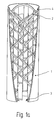
- a static mixer according to the invention is in a perspective View shown; the housing 1 is shown cut away.
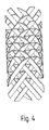
- Figure 4 shows a view along the webs of a grid. It can be seen that the Bars 2a, 2b, 2c through the bars 6a, 6b, 6c and 7a, 7b, 7c of the other grids in their Location are fixed. Bridges are only added in the top and bottom layers fixed by the support 3 or the hold-down device 4 (not shown in FIG. 4).
- Figure 5 shows an arrangement of webs for a mixer insert with a square cross-section and with fourfold rotational symmetry of the webs to each other.
- This mixer insert requires a housing 1 with a square cross section.
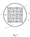
- FIG. 6 shows a mixer / heat exchanger consisting of a Outer housing 10 and an inner housing 1, with nozzle 13 for the product supply and nozzle 14 for product removal, and a supply line 11 and a discharge line 12 for a temperature control medium. Walls between outer housing 10 and inner housing 1 divide the space into two chambers 15 and 16 for the supply and discharge of the heat transfer medium.
- FIG. 9 shows the arrangement of the tubes Bars 17 inside the mixer / heat exchanger. It is marked by four grids with parallel webs, which are at 90 ° to each other Flow direction are arranged rotated.
- a particularly narrow pipe arrangement is achieved in that adjacent grid levels of a grid are arranged offset from one another.
- Figure 10 shows an alternative arrangement of the hollow webs of the mixer insert for a mixer / heat exchanger as shown in Example 4. Adjacent grid levels aligned with each other, the number of grids is four.
- Such a mixer / heat exchanger is particularly suitable for 2-phase flows. Since the distance between the pipes across the flow direction is large compared to the distance in the main flow direction, there are large flow channels for the product. The arrangement of the tubes results in a flow in these flow channels Swirl flow with separation into a gas flow inside the channel and a liquid flow on the outside of the channel. This can cause pressure loss when Flow through such a mixer / heat exchanger can be kept small.
Abstract
Description
Die Erfindung betrifft einen statischen Mischer, bestehend wenigstens aus einem Mischereinsatz, gegebenenfalls einem Auflager und gegebenenfalls einem Niederhalter, mit einem umschließenden Gehäuse, wobei der Mischereinsatz aus einer Vielzahl von ineinander verschachtelten Gittern von zueinander parallelen, in übereinander liegenden Lagen angeordneten Stegen zusammengesetzt ist und wobei die Gitter gegeneinander um einen Winkel α um die Hauptströmungsrichtung durch den Mischer verdreht angeordnet sind.The invention relates to a static mixer consisting of at least one Mixer insert, optionally a support and optionally a hold-down device, with an enclosing housing, the mixer insert consisting of a variety of nested grids, parallel to each other, one on top of the other lying layers arranged webs is composed and wherein the Grid against each other by an angle α around the main flow direction through the Mixers are arranged twisted.
Zum Mischen von insbesondere hochviskosen Flüssigkeiten werden vielfach statische Mischer eingesetzt. Eine Pumpe drückt die Flüssigkeit dabei durch ein mit statischen Mischereinbauten versehenes Rohr, wobei die der Hauptströmungsachse folgende Flüssigkeit in Teilströme aufgeteilt wird, die je nach Art der Einbauten miteinander verwirbelt und vermischt werden.There are many ways to mix particularly viscous liquids static mixer used. A pump presses the liquid through static mixer internals provided pipe, the that of the main flow axis the following liquid is divided into partial flows, depending on the type of internals be swirled and mixed.
Beispielhaft für statische Mischer seien die zwei folgenden Vorrichtungen genannt:The following two devices may be mentioned as examples of static mixers:
Bei den sogenannten Kenics-Mischern (siehe "Mischen beim Herstellen und Verarbeiten von Kunststoffen", Herausgeber VDI Ges. Kunststofftechnik, VDI-Verlag 1986, S. 238-241) wird die Flüssigkeitsströmung des Mischgutes durch ein in ein Rohr eingebautes Trennblech in Teilströme geteilt. Dieses Trennblech ist um die Rohrachse tordiert. In jedem der Teilströme entsteht eine wirbelförmige Strömung, die zur Umverteilung der Flüssigkeit im Querschnitt des Rohres führt. Üblicherweise werden mehrere solcher Mischelemente hintereinander angeordnet, um die Flüssigkeit immer wieder neu zu teilen und ein hinreichendes Mischerergebnis zu erzielen. Eine befriedigende Mischung wird typischerweise erst nach 10 bis 12 Mischelementen erreicht. With the so-called Kenics mixers (see "Mixing during manufacture and processing von Kunststoffe ", publisher VDI Ges. Kunststofftechnik, VDI publishing house 1986, pp. 238-241), the liquid flow of the mixed material is changed into a Pipe installed divider divided into partial flows. This divider is around that Tube axis twisted. A vortex-shaped flow arises in each of the partial flows, which leads to the redistribution of the liquid in the cross section of the tube. Usually several such mixing elements are arranged one behind the other to form the liquid to share again and again and to achieve a sufficient mixer result. A satisfactory mixture is typically only after 10 to 12 mixing elements reached.
Die weiter bekannten sogenannten SMX-Mischer (vgl. Patentschrift US 40 62 524) bestehen aus zwei oder mehr zueinander senkrecht stehenden Gittern von parallelen Blechstreifen, die an ihren Kreuzungspunkten miteinander verschweißt sind und in einem Winkel gegen die Hauptströmungsrichtung des Mischgutes angestellt sind, um die Flüssigkeit in Teilströme zu teilen und zu mischen. Der Herstellungsaufwand für diese Mischer ist wegen der vielen zu tätigenden Schweißverbindungen sehr hoch. Ein einzelnes Mischelement ist als Mischer ungeeignet, da eine Durchmischung nur entlang einer Vorzugsrichtung quer zur Hauptströmungsrichtung erfolgt. Deshalb müssen mehrere Mischelemente, die zueinander um 90° verdreht sind, hintereinander angeordnet werden. Eine gute Durchmischung erfordert typischerweise 5 bis 6 hintereinander angeordnete Mischerelemente.The further known so-called SMX mixers (cf. patent specification US 40 62 524) consist of two or more mutually perpendicular grids of parallel Metal strips that are welded together at their crossing points and in are made at an angle to the main flow direction of the mix, in order to to divide and mix the liquid into partial flows. The manufacturing effort for this mixer is very high because of the many welded joints to be made. A single mixing element is unsuitable as a mixer because it only mixes takes place along a preferred direction transverse to the main flow direction. Therefore several mixing elements, which are rotated by 90 ° to each other, must be used one after the other to be ordered. Good mixing typically requires 5 to 6 mixer elements arranged one behind the other.
Dies lässt sich wie folgt erklären: Ein SMX-Mischer weist nur zwei gegeneinander um 180° verdrehte Gitter paralleler Stege auf. Diese Gitter bestehen aus Lagen äquidistanter Stege. Benachbarte Lagen sind zueinander fluchtend angeordnet. Jede Lage stellt eine Symmetrieebene dar, die bei der Mischung nicht überquert wird.This can be explained as follows: An SMX mixer only points two against each other grid of parallel webs rotated by 180 °. These grids consist of layers more equidistant Walkways. Adjacent layers are aligned. Any location represents a plane of symmetry that is not crossed when mixing.
Aufgabe der Erfindung ist es, einen statischen Mischer bereit zu stellen, der die Mischwirkung der bekannten Mischer, insbesondere des SMX-Mischers, übertrifft und mit einem minimalen Fertigungsaufwand herzustellen ist.The object of the invention is to provide a static mixer which the Mixing effect of the known mixer, especially the SMX mixer, exceeds and can be produced with a minimal manufacturing outlay.
Die Aufgabe wird erfindungsgemäß gelöst durch einen statischen Mischer bestehend wenigstens aus einem Gehäuse mit gegebenenfalls einem Auflager und eventuell einem Niederhalter und mit einem Mischereinsatz bestehend aus mindestens drei gegeneinander um die Strömungsrichtung verdrehten Gittern paralleler Stege, die zur Strömungsrichtung angestellt sind.The object is achieved according to the invention by a static mixer at least from a housing with possibly a support and possibly a hold-down and with a mixer insert consisting of at least three against each other parallel webs twisted around the direction of flow, leading to Flow direction are set.
Gegenstand der Erfindung ist ein Statischer Mischer bestehend wenigstens aus einem Mischereinsatz, gegebenenfalls einem Auflager und gegebenenfalls einem Niederhalter, mit einem umschließenden Gehäuse, wobei der Mischereinsatz aus mindestens drei ineinander verschachtelten Gittern von zueinander parallelen, in übereinander liegenden Lagen angeordneten Stegen zusammengesetzt ist und wobei die Gitter gegeneinander um einen Winkel α um die Hauptströmungsrichtung durch den Mischer verdreht angeordnet sind.The invention relates to a static mixer consisting of at least one Mixer insert, optionally a support and optionally a hold-down device, with an enclosing housing, the mixer insert consisting of at least three nested grids of parallel to each other, one on top of the other lying layers arranged webs is composed and wherein the Grid against each other by an angle α around the main flow direction through the Mixers are arranged twisted.
Bei dieser Konstruktion können die Stege eines Gitters durch die Stege der anderen Gitter in ihrer Position gehalten werden ohne dass sie miteinander verbunden werden müssen. Deshalb ist kein zusätzlicher Aufwand für das Zusammenschweißen der Stege bei dieser Konstruktionsweise erforderlich.With this construction, the bars of one grating can pass through the bars of the other Grids are held in position without being connected have to. Therefore, there is no additional effort for welding the Bridges required in this construction.
Auf Grund der erfindungsgemäßen Anordnung gibt es keine Spiegelsymmetrieebene, so dass die Mischwirkung biaxial erfolgt.Because of the arrangement according to the invention, there is no mirror symmetry plane, so that the mixing effect is biaxial.
Eine bevorzugte Ausführung des statischen Mischers ist dadurch gekennzeichnet, dass die Stege zur Hauptströmungsrichtung durch den Mischer um einen Winkel β bevorzugt von 30 bis 60°, angestellt sind.A preferred embodiment of the static mixer is characterized in that that the webs to the main flow direction through the mixer by an angle β preferably from 30 to 60 °.
In einer bevorzugten Variante des statischen Mischers sind die Stege eines Gitters durch die Stege der anderen Gitter, das Gehäuse sowie bei den endständigen Stegen durch das Auflager und/oder den Niederhalter in ihrer Position fixiert.In a preferred variant of the static mixer, the webs are a grid through the webs of the other grilles, the housing and the end webs fixed in position by the support and / or the hold-down device.
Vorzugsweise beträgt die Anzahl der Gitter des Mischereinsatzes des statischen Mischers drei oder vier.The number of grids in the mixer insert is preferably static Mixer three or four.
Insbesondere bevorzugt ist der statische Mischer rotationssymmetrisch entsprechend der Anzahl der Gitter aufgebaut.The static mixer is particularly preferably rotationally symmetrical the number of grids built up.
Eine bevorzugte Ausführung des statischen Mischers ist dadurch gekennzeichnet, dass drei Gitter mit parallelen Stegen aus parallelen Lagen von Stegen aufgebaut sind, wobei jeweils benachbarte Lagen zueinander auf Lücke sitzen. A preferred embodiment of the static mixer is characterized in that that three grids with parallel webs are built from parallel layers of webs are, with adjacent layers each sitting on a gap.
Eine andere bevorzugte Ausführung des statischen Mischers ist dadurch gekennzeichnet, dass vier Gitter mit parallelen Stegen aus parallelen Lagen von Stegen aufgebaut sind, wobei benachbarte Lagen miteinander fluchten.Another preferred embodiment of the static mixer is characterized in that that four grids with parallel webs are built from parallel layers of webs are, with adjacent layers aligned with each other.
In einer weiteren bevorzugten Form des statischen Mischers sind benachbarte Gitterebenen eines Gitters gegeneinander versetzt angeordnet und die Anzahl der Gitter beträgt vier.In a further preferred form of the static mixer, adjacent lattice planes are of a grid is offset from each other and the number of grids is four.
Wenn der statische Mischer auch als Wärmetauscher verwendet werden soll, können die Stege als Hohlstege ausgebildet werden, die in der Gehäusewand münden, wobei die Gehäusewand eine in mehrere Kammern geteilte Ummantelung mit Zuführungen und Ableitungen für ein Wärmeträgermedium aufweist.If the static mixer is also to be used as a heat exchanger, you can the webs are designed as hollow webs which open into the housing wall, wherein the housing wall is a casing with feeds divided into several chambers and has derivatives for a heat transfer medium.
Weiterer Gegenstand der Erfindung ist die Verwendung des erfindungsgemäßen statischen Mischers zur Mischung von hochviskosem Mischgut, insbesondere von Polymerschmelzen oder Polymerlösungen mit Zusatzstoffen, anderen Polymeren, Farbstoffen, Pigmenten oder Stabilisierungsmitteln.Another object of the invention is the use of the invention static mixer for mixing highly viscous mix, in particular Polymer melts or polymer solutions with additives, other polymers, Dyes, pigments or stabilizers.
Die Erfindung wird nachfolgend anhand der Figuren durch die Beispiele, welche jedoch keine Beschränkung der Erfindung darstellen, weiter erläutert.The invention is explained below with reference to the figures by the examples which however, do not constitute a limitation of the invention, explained further.
Es zeigen:
- Figur 1a
- einen erfindungsgemäßen Mischer in einer perspektivischen Ansicht, dabei ist das Gehäuse geschnitten dargestellt.
- Figur 1b
- den Mischer aus Figur 1a in der Draufsicht
Figur 2- das Gehäuse des Mischers aus Figur 1 im Längsschnitt
Figur 3- die Anordnung der Stege innerhalb des Mischers aus Figur 1a in perspektivischer Ansicht
- Figur 4
- die Anordnung der Stege innerhalb des Mischers aus Figur la bei Blickrichtung entlang der Stege
- Figur 5
- eine Anordnung von Stegen für einen Mischer mit einem quadratischen Querschnitt und mit vierzähliger Rotationssymmetrie
- Figur 6
- die Seitenansicht eines erfindungsgemäßen Mischers in der Funktion als Wärmetauscher
Figur 7- den Querschnitt durch den Mischer/Wärmetauscher aus Fig. 6
Figur 8- den Längsschnitt durch den Mischer/Wärmetauscher aus Fig. 6
Figur 9- den Mischereinsatz im Mischer/Wärmetauscher aus Fig. 6
Figur 10- einen alternativen Mischereinsatz mit vier Gittern
- Figure 1a
- a mixer according to the invention in a perspective view, the housing is shown in section.
- Figure 1b
- the mixer of Figure 1a in plan view
- Figure 2
- the housing of the mixer from Figure 1 in longitudinal section
- Figure 3
- the arrangement of the webs within the mixer of Figure 1a in a perspective view
- Figure 4
- the arrangement of the webs within the mixer of Figure la when looking along the webs
- Figure 5
- an arrangement of webs for a mixer with a square cross-section and with four-fold rotational symmetry
- Figure 6
- the side view of a mixer according to the invention in the function as a heat exchanger
- Figure 7
- the cross section through the mixer / heat exchanger from FIG. 6
- Figure 8
- the longitudinal section through the mixer / heat exchanger from FIG. 6
- Figure 9
- the mixer insert in the mixer / heat exchanger from FIG. 6
- Figure 10
- an alternative mixer insert with four grids
In Figur 1a ist ein erfindungsgemäßer statischer Mischer in einer perspektivischen Ansicht dargestellt; dabei ist das Gehäuse 1 aufgeschnitten dargestellt.In Figure 1a, a static mixer according to the invention is in a perspective View shown; the housing 1 is shown cut away.
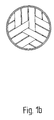
In der Draufsicht auf den Mischer gemäß Figur 1b ist zu erkennen, dass der Mischer dreifach rotationssymmetrisch um die Strömungsmischung aufgebaut ist.In the top view of the mixer according to FIG. 1b it can be seen that the mixer is constructed three times rotationally symmetrical around the flow mixture.
Im Längsschnitt des Gehäuses 1 in Figur 2 ist die Anordnung des Auflagers 3 und
des Niederhalters 4 zu erkennen.In the longitudinal section of the housing 1 in Figure 2, the arrangement of the
In der Darstellung des bloßen Mischereinsatzes nach Figur 3 ist zu erkennen, dass die
drei ineinander verschachtelten Gitter mit parallelen Stegen aus parallelen Lagen 5a,
5b von Stegen 2a, 2b, 2c; 6a, 6b, 6c; 7a, 7b, 7c aufgebaut sind, wobei benachbarte
Lagen 5a (mit den Stegen 2a, 2b, 2c) und 5b (mit den Stegen 12a, 12b, 12c) zueinander
auf Lücke sitzen.In the representation of the mere mixer insert according to Figure 3 it can be seen that the
three nested grids with parallel webs of
Figur 4 zeigt einen Blick entlang der Stege eines Gitters. Es ist zu erkennen, dass die
Stege 2a, 2b, 2c durch die Stege 6a, 6b, 6c bzw. 7a, 7b, 7c der anderen Gitter in ihrer
Lage fixiert sind. Nur in der obersten und untersten Lage werden Stege zusätzlich
durch das Auflager 3 bzw. den Niederhalter 4 (in Fig. 4 nicht gezeichnet) fixiert.Figure 4 shows a view along the webs of a grid. It can be seen that the
Figur 5 zeigt eine Anordnung von Stegen für einen Mischereinsatz mit einem quadratischen Querschnitt und mit vierzähliger Rotationssymmetrie der Stege zueinander. Dieser Mischereinsatz erfordert ein Gehäuse 1 mit quadratischem Querschnitt. Figure 5 shows an arrangement of webs for a mixer insert with a square cross-section and with fourfold rotational symmetry of the webs to each other. This mixer insert requires a housing 1 with a square cross section.
Die Figuren 6, 7 und 8 zeigen einen Mischer/Wärmetauscher bestehend aus einem
Außengehäuse 10 und einem Innengehäuse 1, mit Stutzen 13 für die Produktzufuhr
und Stutzen 14 für die Produktabfuhr, sowie einer Zuleitung 11 und einer Ableitung
12 für ein Temperiermedium. Wände zwischen Außengehäuse 10 und Innengehäuse
1 teilen den Zwischenraum in zwei Kammern 15 und 16 für die Zu- und Ableitung
des Wärmeträgermediums. Figur 9 zeigt die Anordnung der als Rohre ausgebildeten
Stege 17 im Inneren des Mischer/Wärmetauschers. Sie ist gekennzeichnet
durch vier Gitter mit parallelen Stegen, die gegeneinander um 90° bezüglich der
Strömungsrichtung verdreht angeordnet sind.Figures 6, 7 and 8 show a mixer / heat exchanger consisting of a
Eine besonders enge Rohranordnung wird dadurch erreicht, dass benachbarte Gitterebenen eines Gitters gegeneinander versetzt angeordnet sind.A particularly narrow pipe arrangement is achieved in that adjacent grid levels of a grid are arranged offset from one another.
Figur 10 zeigt eine alternative Anordnung der Hohlstege des Mischereinsatzes für einen Mischer/Wärmetauscher wie in Beispiel 4 dargestellt. Benachbarte Gitterebenen fluchten miteinander, die Anzahl der Gitter beträgt vier.Figure 10 shows an alternative arrangement of the hollow webs of the mixer insert for a mixer / heat exchanger as shown in Example 4. Adjacent grid levels aligned with each other, the number of grids is four.
Solch ein Mischer/Wärmetauscher ist besonders für 2-phasige Strömungen geeignet. Da der Abstand der Rohre quer zur Strömungsrichtung groß ist gegenüber dem Abstand in Hauptströmungsrichtung, ergeben sich große Strömungskanäle für das Produkt. Durch die Anordnung der Rohre ergibt sich in diesen Strömungskanälen eine Drallströmung mit Trennung in eine Gasströmung im Kanalinneren und eine Flüssigkeitsströmung an der Außenseite des Kanals. Dadurch kann der Druckverlust beim Durchströmen eines solchen Mischer/Wärmetauschers klein gehalten werden.Such a mixer / heat exchanger is particularly suitable for 2-phase flows. Since the distance between the pipes across the flow direction is large compared to the distance in the main flow direction, there are large flow channels for the product. The arrangement of the tubes results in a flow in these flow channels Swirl flow with separation into a gas flow inside the channel and a liquid flow on the outside of the channel. This can cause pressure loss when Flow through such a mixer / heat exchanger can be kept small.
Claims (13)
Priority Applications (1)
| Application Number | Priority Date | Filing Date | Title |
|---|---|---|---|
| DK01101637T DK1123730T3 (en) | 2000-02-08 | 2001-01-26 | Static mixer |
Applications Claiming Priority (2)
| Application Number | Priority Date | Filing Date | Title |
|---|---|---|---|
| DE10005457 | 2000-02-08 | ||
| DE10005457A DE10005457A1 (en) | 2000-02-08 | 2000-02-08 | Static mixer |
Publications (3)
| Publication Number | Publication Date |
|---|---|
| EP1123730A2 true EP1123730A2 (en) | 2001-08-16 |
| EP1123730A3 EP1123730A3 (en) | 2003-05-02 |
| EP1123730B1 EP1123730B1 (en) | 2004-11-03 |
Family
ID=7630174
Family Applications (1)
| Application Number | Title | Priority Date | Filing Date |
|---|---|---|---|
| EP01101637A Expired - Lifetime EP1123730B1 (en) | 2000-02-08 | 2001-01-26 | Static mixer |
Country Status (9)
| Country | Link |
|---|---|
| US (1) | US6595679B2 (en) |
| EP (1) | EP1123730B1 (en) |
| JP (1) | JP2001246234A (en) |
| AT (1) | ATE281230T1 (en) |
| CA (1) | CA2333839C (en) |
| DE (2) | DE10005457A1 (en) |
| DK (1) | DK1123730T3 (en) |
| ES (1) | ES2232527T3 (en) |
| PT (1) | PT1123730E (en) |
Cited By (14)
| Publication number | Priority date | Publication date | Assignee | Title |
|---|---|---|---|---|
| WO2004098759A1 (en) * | 2003-05-03 | 2004-11-18 | Husky Injection Molding Systems Ltd. | Static mixer and a method of manufacture thereof |
| EP1967806A1 (en) * | 2007-03-09 | 2008-09-10 | Sulzer Chemtech AG | Device for heat exchange and mixing treatment of fluid mediums |
| WO2009000642A1 (en) | 2007-06-22 | 2008-12-31 | Sulzer Chemtech Ag | Static mixing element |
| FR2929856A1 (en) * | 2008-04-15 | 2009-10-16 | Rhodia Operations Sas | PROCESS FOR THE PREPARATION OF CRYSTALS BASED ON A FATTY ACID ESTER |
| WO2011006613A2 (en) | 2009-07-17 | 2011-01-20 | Bayer Technology Services Gmbh | Heat exchange module and compact heat exchangers |
| EP2629039A1 (en) | 2012-02-17 | 2013-08-21 | Armacell Enterprise GmbH | Extensional flow heat exchanger for polymer melts |
| US8628233B2 (en) | 2007-05-24 | 2014-01-14 | Atlas Holding Ag | Flow channel for a mixer heat exchanger |
| EP2851118A1 (en) | 2013-09-20 | 2015-03-25 | Promix Solutions AG | Device for mixing and for heat exchange and method for its production |
| EP2865503A1 (en) | 2013-09-20 | 2015-04-29 | Promix Solutions AG | Method for producing low density foams |
| WO2017129768A1 (en) * | 2016-01-29 | 2017-08-03 | Basf Se | Hollow chamber x-mixer heat exchanger |
| EP3489603A1 (en) | 2017-11-28 | 2019-05-29 | Promix Solutions AG | Heat exchanger |
| EP3822569A1 (en) | 2019-11-14 | 2021-05-19 | Promix Solutions AG | Heat exchanger |
| DE102019009099A1 (en) * | 2019-12-31 | 2021-07-01 | Heinz Gross | Heat exchanger with mixing function |
| EP4089357A1 (en) | 2021-05-10 | 2022-11-16 | Promix Solutions AG | Heat exchanger |
Families Citing this family (32)
| Publication number | Priority date | Publication date | Assignee | Title |
|---|---|---|---|---|
| DE20002920U1 (en) | 2000-02-18 | 2000-04-20 | Schroeder & Boos Misch Und Anl | Homogenizer |
| DE10158651B4 (en) * | 2001-11-30 | 2016-02-04 | Ritter Gmbh | Static mixing element |
| DE10162124A1 (en) * | 2001-12-18 | 2003-07-03 | Plamex Maschb Gmbh | Static mixer for plastic melt has spheres packed between perforated end plates of a housing |
| CA2491755C (en) * | 2002-07-15 | 2010-06-22 | Sulzer Chemtech Usa, Inc. | Assembly of crossing elements and method of constructing same |
| CA2460292C (en) | 2003-05-08 | 2011-08-23 | Sulzer Chemtech Ag | A static mixer |
| DE10334593B3 (en) * | 2003-07-28 | 2005-04-21 | Framatome Anp Gmbh | mixing system |
| US7080937B1 (en) | 2003-11-13 | 2006-07-25 | Automatic Bar Controls, Inc. | Nonclogging static mixer |
| FR2892644B1 (en) * | 2005-10-28 | 2008-02-08 | Snecma Propulsion Solide Sa | TRAPPING STRUCTURE FOR FLUID EXCHANGE COLUMN |
| US9485917B2 (en) | 2006-12-15 | 2016-11-08 | Ecovative Design, LLC | Method for producing grown materials and products made thereby |
| US8295692B2 (en) * | 2007-02-12 | 2012-10-23 | Gaumer Company, Inc. | Scissor baffles for fuel gas conditioning system |
| US8391696B2 (en) * | 2007-02-12 | 2013-03-05 | Gaumer Company, Inc. | Fuel gas conditioning system with scissor baffles |
| DE102007040850A1 (en) * | 2007-08-29 | 2009-03-05 | Wacker Chemie Ag | Process for the preparation of protective colloid-stabilized polymers and apparatus for carrying out the process |
| EP2042284B1 (en) * | 2007-09-27 | 2011-08-03 | Sulzer Chemtech AG | Device for creating a reactionable flowable compound and its use |
| DE102010019771A1 (en) * | 2010-05-07 | 2011-11-10 | Dürr Systems GmbH | Atomizer with a lattice mixer |
| US11277979B2 (en) | 2013-07-31 | 2022-03-22 | Ecovative Design Llc | Mycological biopolymers grown in void space tooling |
| US20150101509A1 (en) | 2013-10-14 | 2015-04-16 | Gavin R. McIntyre | Method of Manufacturing a Stiff Engineered Composite |
| US9162206B2 (en) | 2013-12-05 | 2015-10-20 | Exxonmobil Research And Engineering Company | Reactor bed component for securing rigid assemblies |
| US10406497B2 (en) | 2013-12-05 | 2019-09-10 | Exxonmobil Research And Engineering Company | Reactor bed vessel and support assembly |
| US9636652B2 (en) | 2013-12-05 | 2017-05-02 | Exxonmobil Research And Engineering Company | Reactor bed vessel and support assembly |
| DE102014216431A1 (en) * | 2014-08-19 | 2016-02-25 | Schunk Kohlenstofftechnik Gmbh | Static mixer with a porous structure formed in a porous body and method for producing a porous body |
| FR3040894A1 (en) * | 2015-09-15 | 2017-03-17 | Ifp Energies Now | OPTIMIZED TRIM STRUCTURE FOR FLUID CONTACT COLUMN AND METHOD OF MANUFACTURE |
| MX2018005990A (en) | 2015-11-13 | 2018-11-29 | Re Mixers Inc | Static mixer. |
| CN109153964B (en) | 2016-03-01 | 2023-06-13 | 芬德集团公司 | Filamentous fungus biological mats, methods of producing and using the same |
| CN105597584A (en) * | 2016-03-11 | 2016-05-25 | 济南正骐生物科技有限公司 | Static mixer |
| US9909478B2 (en) | 2016-05-02 | 2018-03-06 | Caterpillar Inc. | Mixer for exhaust aftertreatment systems |
| US10012125B2 (en) | 2016-05-02 | 2018-07-03 | Caterpillar Inc. | Dual mixer for exhaust aftertreatment systems |
| BR112019020132B1 (en) | 2017-03-31 | 2023-12-05 | Ecovative Design, LLC | Processed mycological biopolymer material and respective preparation method |
| US11266085B2 (en) | 2017-11-14 | 2022-03-08 | Ecovative Design Llc | Increased homogeneity of mycological biopolymer grown into void space |
| US11920126B2 (en) | 2018-03-28 | 2024-03-05 | Ecovative Design Llc | Bio-manufacturing process |
| US11293005B2 (en) | 2018-05-07 | 2022-04-05 | Ecovative Design Llc | Process for making mineralized mycelium scaffolding and product made thereby |
| WO2019226823A1 (en) | 2018-05-24 | 2019-11-28 | Ecovative Design Llc | Process and apparatus for producing mycelium biomaterial |
| WO2020072140A1 (en) | 2018-10-02 | 2020-04-09 | Ecovative Design Llc | A bioreactor paradigm for the production of secondary extra-particle hyphal matrices |
Citations (3)
| Publication number | Priority date | Publication date | Assignee | Title |
|---|---|---|---|---|
| US4062524A (en) * | 1973-06-06 | 1977-12-13 | Bayer Aktiengesellschaft | Apparatus for the static mixing of fluid streams |
| US4692030A (en) * | 1984-03-05 | 1987-09-08 | Sulzer Brothers Limited | Static mixing device for viscous melts |
| EP0412177A1 (en) * | 1988-05-02 | 1991-02-13 | Kama Corporation | Static mixing device |
Family Cites Families (26)
| Publication number | Priority date | Publication date | Assignee | Title |
|---|---|---|---|---|
| US3827676A (en) * | 1972-10-02 | 1974-08-06 | Dow Chemical Co | Interfacial surface generator |
| CH578369A5 (en) * | 1974-05-10 | 1976-08-13 | Sulzer Ag | |
| DE2522106C3 (en) * | 1975-05-17 | 1982-04-15 | Bayer Ag, 5090 Leverkusen | Device for the continuous mixing of flowable substances and method for producing a mixing insert |
| US4072296A (en) * | 1975-07-16 | 1978-02-07 | Doom Lewis G | Motionless mixer |
| JPS53139672U (en) * | 1977-04-11 | 1978-11-04 | ||
| DE2808854C2 (en) * | 1977-05-31 | 1986-05-28 | Gebrüder Sulzer AG, 8401 Winterthur | Flow channel provided with internals for a medium involved in an indirect exchange, in particular heat exchange |
| CH642564A5 (en) * | 1979-10-26 | 1984-04-30 | Sulzer Ag | STATIC MIXING DEVICE. |
| USRE34255E (en) * | 1988-05-02 | 1993-05-18 | Krup Corporation | Static mixing device |
| CH678284A5 (en) * | 1988-11-03 | 1991-08-30 | Sulzer Ag | Static mixer assembly requiring no cleaning - in which inner face of tube segments bear ridges which cross each other diagonally with respect to tubular axis |
| JPH0377636A (en) * | 1989-08-17 | 1991-04-03 | Karma Corp | Static agitator |
| EP0646408B1 (en) * | 1993-10-05 | 1999-12-01 | Sulzer Chemtech AG | Device for homogenising very viscous liquids |
| US5378063A (en) * | 1993-12-02 | 1995-01-03 | Tokyo Nisshin Jabara Co., Ltd. | Static mixing module |
| JP2678267B2 (en) * | 1994-05-09 | 1997-11-17 | 修 高橋 | Heat exchange type tube mixer |
| DE4428813C2 (en) * | 1994-08-13 | 1996-11-14 | Ewald Schwing Verfahrenstechni | Device for static mixing of fluids, in particular thermoplastic, and method for producing such a device |
| US5484203A (en) * | 1994-10-07 | 1996-01-16 | Komax Systems Inc. | Mixing device |
| EP0727249B1 (en) * | 1995-02-02 | 1999-05-06 | Sulzer Chemtech AG | Static mixer for very viscous liquids |
| JPH08281652A (en) * | 1995-04-13 | 1996-10-29 | Unitika Ltd | Transport pipe for thermoplastic polymer |
| JPH0957742A (en) * | 1995-08-24 | 1997-03-04 | Asahi Chem Ind Co Ltd | Method for continuous mixing of additive into molten styrene resin |
| DE59505850D1 (en) * | 1995-08-30 | 1999-06-10 | Sulzer Chemtech Ag | Static mixer for viscous fluids |
| ES2144595T3 (en) * | 1995-10-05 | 2000-06-16 | Sulzer Chemtech Ag | MIXING DEVICE OF A VERY VISCOUS FLUID WITH A LITTLE VISCOUS FLUID. |
| EP0856353B1 (en) * | 1997-01-29 | 2002-05-15 | Sulzer Chemtech AG | Module for a static mixer for a resident time critical plastic flowable mixture |
| WO1999000180A1 (en) * | 1997-06-26 | 1999-01-07 | Robbins & Myers, Inc. | Multi-component static mixer and method of operation |
| DE19827851A1 (en) * | 1998-06-23 | 1999-12-30 | Bayer Ag | Static mixing device |
| DE19837671A1 (en) * | 1998-08-20 | 2000-02-24 | Bayer Ag | Static mixer |
| US6394644B1 (en) * | 1999-06-21 | 2002-05-28 | Koch-Glitsch, Inc. | Stacked static mixing elements |
| EP1067352B1 (en) * | 1999-07-07 | 2003-08-27 | Fluitec Georg AG | Heat exchange device |
-
2000
- 2000-02-08 DE DE10005457A patent/DE10005457A1/en not_active Withdrawn
-
2001
- 2001-01-26 AT AT01101637T patent/ATE281230T1/en not_active IP Right Cessation
- 2001-01-26 DE DE50104336T patent/DE50104336D1/en not_active Expired - Lifetime
- 2001-01-26 ES ES01101637T patent/ES2232527T3/en not_active Expired - Lifetime
- 2001-01-26 DK DK01101637T patent/DK1123730T3/en active
- 2001-01-26 PT PT01101637T patent/PT1123730E/en unknown
- 2001-01-26 EP EP01101637A patent/EP1123730B1/en not_active Expired - Lifetime
- 2001-02-05 JP JP2001028507A patent/JP2001246234A/en active Pending
- 2001-02-05 CA CA002333839A patent/CA2333839C/en not_active Expired - Fee Related
- 2001-02-07 US US09/778,690 patent/US6595679B2/en not_active Expired - Fee Related
Patent Citations (3)
| Publication number | Priority date | Publication date | Assignee | Title |
|---|---|---|---|---|
| US4062524A (en) * | 1973-06-06 | 1977-12-13 | Bayer Aktiengesellschaft | Apparatus for the static mixing of fluid streams |
| US4692030A (en) * | 1984-03-05 | 1987-09-08 | Sulzer Brothers Limited | Static mixing device for viscous melts |
| EP0412177A1 (en) * | 1988-05-02 | 1991-02-13 | Kama Corporation | Static mixing device |
Cited By (26)
| Publication number | Priority date | Publication date | Assignee | Title |
|---|---|---|---|---|
| WO2004098759A1 (en) * | 2003-05-03 | 2004-11-18 | Husky Injection Molding Systems Ltd. | Static mixer and a method of manufacture thereof |
| EP1967806A1 (en) * | 2007-03-09 | 2008-09-10 | Sulzer Chemtech AG | Device for heat exchange and mixing treatment of fluid mediums |
| JP2008224205A (en) * | 2007-03-09 | 2008-09-25 | Sulzer Chemtech Ag | Device for heat exchange and mixing of fluid medium |
| US8794820B2 (en) | 2007-03-09 | 2014-08-05 | Sulzer Chemtech Ag | Apparatus for the heat-exchanging and mixing treatment of fluid media |
| US8628233B2 (en) | 2007-05-24 | 2014-01-14 | Atlas Holding Ag | Flow channel for a mixer heat exchanger |
| WO2009000642A1 (en) | 2007-06-22 | 2008-12-31 | Sulzer Chemtech Ag | Static mixing element |
| EP2277620A3 (en) * | 2007-06-22 | 2011-02-16 | Sulzer Chemtech AG | Static mixing element |
| CN102861522A (en) * | 2007-06-22 | 2013-01-09 | 苏舍化学技术有限公司 | Static mixing element |
| CN101743055B (en) * | 2007-06-22 | 2013-03-27 | 苏舍化学技术有限公司 | Static mixing element |
| US8491180B2 (en) | 2007-06-22 | 2013-07-23 | Sulzer Chemtech Ag | Static mixing element |
| EP2158027B2 (en) † | 2007-06-22 | 2016-04-27 | Sulzer Chemtech AG | Static mixing element |
| WO2009127596A1 (en) * | 2008-04-15 | 2009-10-22 | Rhodia Operations | Method for preparing fatty acid ester crystals |
| US20110071308A1 (en) * | 2008-04-15 | 2011-03-24 | Rhodia Operations | Process for preparing crystals based on a fatty acid ester |
| US8536356B2 (en) | 2008-04-15 | 2013-09-17 | Rhodia Operations | Process for preparing crystals based on a fatty acid ester |
| FR2929856A1 (en) * | 2008-04-15 | 2009-10-16 | Rhodia Operations Sas | PROCESS FOR THE PREPARATION OF CRYSTALS BASED ON A FATTY ACID ESTER |
| WO2011006613A2 (en) | 2009-07-17 | 2011-01-20 | Bayer Technology Services Gmbh | Heat exchange module and compact heat exchangers |
| DE112010002969B4 (en) * | 2009-07-17 | 2017-11-16 | Ehrfeld Mikrotechnik Bts Gmbh | Heat exchanger module and heat exchanger in a compact design |
| EP2629039A1 (en) | 2012-02-17 | 2013-08-21 | Armacell Enterprise GmbH | Extensional flow heat exchanger for polymer melts |
| EP2851118A1 (en) | 2013-09-20 | 2015-03-25 | Promix Solutions AG | Device for mixing and for heat exchange and method for its production |
| EP2865503A1 (en) | 2013-09-20 | 2015-04-29 | Promix Solutions AG | Method for producing low density foams |
| WO2017129768A1 (en) * | 2016-01-29 | 2017-08-03 | Basf Se | Hollow chamber x-mixer heat exchanger |
| EP3489603A1 (en) | 2017-11-28 | 2019-05-29 | Promix Solutions AG | Heat exchanger |
| US11085710B2 (en) | 2017-11-28 | 2021-08-10 | Promix Solutions Ag | Heat exchanger |
| EP3822569A1 (en) | 2019-11-14 | 2021-05-19 | Promix Solutions AG | Heat exchanger |
| DE102019009099A1 (en) * | 2019-12-31 | 2021-07-01 | Heinz Gross | Heat exchanger with mixing function |
| EP4089357A1 (en) | 2021-05-10 | 2022-11-16 | Promix Solutions AG | Heat exchanger |
Also Published As
| Publication number | Publication date |
|---|---|
| US6595679B2 (en) | 2003-07-22 |
| EP1123730B1 (en) | 2004-11-03 |
| US20010012235A1 (en) | 2001-08-09 |
| DE50104336D1 (en) | 2004-12-09 |
| ATE281230T1 (en) | 2004-11-15 |
| DE10005457A1 (en) | 2001-08-09 |
| PT1123730E (en) | 2005-03-31 |
| DK1123730T3 (en) | 2005-02-14 |
| CA2333839A1 (en) | 2001-08-08 |
| EP1123730A3 (en) | 2003-05-02 |
| ES2232527T3 (en) | 2005-06-01 |
| CA2333839C (en) | 2009-10-06 |
| JP2001246234A (en) | 2001-09-11 |
Similar Documents
| Publication | Publication Date | Title |
|---|---|---|
| EP1123730B1 (en) | Static mixer | |
| EP1216747B1 (en) | Static mixer | |
| EP2158027B2 (en) | Static mixing element | |
| EP3386617B1 (en) | Mixing insert, static mixer and productionmethod | |
| EP0154013B1 (en) | Static mixer, especially for apparatuses processing highly viscous plastics melts | |
| EP0526392B1 (en) | Mixing-in device for small amounts of fluid | |
| EP0226879B1 (en) | Static mixer for fluids containing or composed of solid particles | |
| EP0760253B1 (en) | Static mixer for viscous fluids | |
| DE2708200C2 (en) | Static mixing device for a plastics machine, in particular an injection molding machine or extruder | |
| EP1510247B1 (en) | Static mixer with polymorphous structure | |
| EP1924346B1 (en) | Mixing element for the inversion and mixture of flowing materials in a flow channel, as well as kit and mixer comprising such mixing elements | |
| DE1236479B (en) | Device for mixing flowing media, with stationary guide elements | |
| EP2001580B1 (en) | Static mixer, and process for producing the same | |
| EP3408014A1 (en) | Hollow chamber x-mixer heat exchanger | |
| EP3265656B1 (en) | Mixing box | |
| EP0980703B1 (en) | Static mixer | |
| DE102015102311A1 (en) | Shell and tube heat exchanger | |
| EP3495036A1 (en) | Mixer insert for static mixer, static mixer and method of manufacturing | |
| DE2622530A1 (en) | MIXING DEVICE | |
| DE10322922A1 (en) | Static mixer, for mixing at least two components with paste consistency, e.g. in plastics injection molding, has successive mixing elements within pipe, with deflectors to move material to center with low flow resistance | |
| DE1901281C3 (en) | Device for mixing flowing media | |
| EP3645149B1 (en) | Distributor for a fluid | |
| EP1837070A1 (en) | Static mixer, and method of manufacturing the same | |
| DE2307616A1 (en) | EXTRUDER SCREW | |
| DE2629293A1 (en) | STATIC MIXER |
Legal Events
| Date | Code | Title | Description |
|---|---|---|---|
| PUAI | Public reference made under article 153(3) epc to a published international application that has entered the european phase |
Free format text: ORIGINAL CODE: 0009012 |
|
| AK | Designated contracting states |
Kind code of ref document: A2 Designated state(s): AT BE CH CY DE DK ES FI FR GB GR IE IT LI LU MC NL PT SE TR |
|
| AX | Request for extension of the european patent |
Free format text: AL;LT;LV;MK;RO;SI |
|
| PUAL | Search report despatched |
Free format text: ORIGINAL CODE: 0009013 |
|
| AK | Designated contracting states |
Designated state(s): AT BE CH CY DE DK ES FI FR GB GR IE IT LI LU MC NL PT SE TR |
|
| AX | Request for extension of the european patent |
Extension state: AL LT LV MK RO SI |
|
| 17P | Request for examination filed |
Effective date: 20031103 |
|
| AKX | Designation fees paid |
Designated state(s): AT BE CH CY DE DK ES FI FR GB GR IE IT LI LU MC NL PT SE TR |
|
| GRAP | Despatch of communication of intention to grant a patent |
Free format text: ORIGINAL CODE: EPIDOSNIGR1 |
|
| RAP1 | Party data changed (applicant data changed or rights of an application transferred) |
Owner name: BAYER TECHNOLOGY SERVICES GMBH |
|
| GRAS | Grant fee paid |
Free format text: ORIGINAL CODE: EPIDOSNIGR3 |
|
| GRAA | (expected) grant |
Free format text: ORIGINAL CODE: 0009210 |
|
| AK | Designated contracting states |
Kind code of ref document: B1 Designated state(s): AT BE CH CY DE DK ES FI FR GB GR IE IT LI LU MC NL PT SE TR |
|
| PG25 | Lapsed in a contracting state [announced via postgrant information from national office to epo] |
Ref country code: TR Free format text: LAPSE BECAUSE OF FAILURE TO SUBMIT A TRANSLATION OF THE DESCRIPTION OR TO PAY THE FEE WITHIN THE PRESCRIBED TIME-LIMIT Effective date: 20041103 |
|
| REG | Reference to a national code |
Ref country code: GB Ref legal event code: FG4D Free format text: NOT ENGLISH |
|
| REG | Reference to a national code |
Ref country code: CH Ref legal event code: EP |
|
| REF | Corresponds to: |
Ref document number: 50104336 Country of ref document: DE Date of ref document: 20041209 Kind code of ref document: P |
|
| PGFP | Annual fee paid to national office [announced via postgrant information from national office to epo] |
Ref country code: GR Payment date: 20041215 Year of fee payment: 5 |
|
| REG | Reference to a national code |
Ref country code: IE Ref legal event code: FG4D Free format text: GERMAN |
|
| PGFP | Annual fee paid to national office [announced via postgrant information from national office to epo] |
Ref country code: IE Payment date: 20041216 Year of fee payment: 5 |
|
| PGFP | Annual fee paid to national office [announced via postgrant information from national office to epo] |
Ref country code: CY Payment date: 20041230 Year of fee payment: 5 |
|
| PGFP | Annual fee paid to national office [announced via postgrant information from national office to epo] |
Ref country code: FI Payment date: 20050105 Year of fee payment: 5 |
|
| PGFP | Annual fee paid to national office [announced via postgrant information from national office to epo] |
Ref country code: DK Payment date: 20050111 Year of fee payment: 5 |
|
| PGFP | Annual fee paid to national office [announced via postgrant information from national office to epo] |
Ref country code: MC Payment date: 20050117 Year of fee payment: 5 |
|
| PGFP | Annual fee paid to national office [announced via postgrant information from national office to epo] |
Ref country code: PT Payment date: 20050119 Year of fee payment: 5 |
|
| PG25 | Lapsed in a contracting state [announced via postgrant information from national office to epo] |
Ref country code: IT Free format text: LAPSE BECAUSE OF NON-PAYMENT OF DUE FEES Effective date: 20050126 |
|
| REG | Reference to a national code |
Ref country code: CH Ref legal event code: NV Representative=s name: E. BLUM & CO. PATENTANWAELTE |
|
| REG | Reference to a national code |
Ref country code: DK Ref legal event code: T3 |
|
| REG | Reference to a national code |
Ref country code: GR Ref legal event code: EP Ref document number: 20040404497 Country of ref document: GR |
|
| REG | Reference to a national code |
Ref country code: SE Ref legal event code: TRGR |
|
| GBT | Gb: translation of ep patent filed (gb section 77(6)(a)/1977) |
Effective date: 20050224 |
|
| REG | Reference to a national code |
Ref country code: PT Ref legal event code: SC4A Free format text: AVAILABILITY OF NATIONAL TRANSLATION Effective date: 20050119 |
|
| REG | Reference to a national code |
Ref country code: ES Ref legal event code: FG2A Ref document number: 2232527 Country of ref document: ES Kind code of ref document: T3 |
|
| PLBE | No opposition filed within time limit |
Free format text: ORIGINAL CODE: 0009261 |
|
| STAA | Information on the status of an ep patent application or granted ep patent |
Free format text: STATUS: NO OPPOSITION FILED WITHIN TIME LIMIT |
|
| ET | Fr: translation filed | ||
| 26N | No opposition filed |
Effective date: 20050804 |
|
| PG25 | Lapsed in a contracting state [announced via postgrant information from national office to epo] |
Ref country code: CY Free format text: LAPSE BECAUSE OF NON-PAYMENT OF DUE FEES Effective date: 20060126 Ref country code: FI Free format text: LAPSE BECAUSE OF NON-PAYMENT OF DUE FEES Effective date: 20060126 Ref country code: IE Free format text: LAPSE BECAUSE OF NON-PAYMENT OF DUE FEES Effective date: 20060126 |
|
| PG25 | Lapsed in a contracting state [announced via postgrant information from national office to epo] |
Ref country code: MC Free format text: LAPSE BECAUSE OF NON-PAYMENT OF DUE FEES Effective date: 20060131 Ref country code: DK Free format text: LAPSE BECAUSE OF NON-PAYMENT OF DUE FEES Effective date: 20060131 |
|
| PGFP | Annual fee paid to national office [announced via postgrant information from national office to epo] |
Ref country code: LU Payment date: 20060213 Year of fee payment: 6 |
|
| REG | Reference to a national code |
Ref country code: GB Ref legal event code: 732E |
|
| PG25 | Lapsed in a contracting state [announced via postgrant information from national office to epo] |
Ref country code: PT Free format text: LAPSE BECAUSE OF NON-PAYMENT OF DUE FEES Effective date: 20060726 |
|
| REG | Reference to a national code |
Ref country code: DK Ref legal event code: EBP |
|
| REG | Reference to a national code |
Ref country code: PT Ref legal event code: MM4A Effective date: 20060726 |
|
| REG | Reference to a national code |
Ref country code: IE Ref legal event code: MM4A |
|
| REG | Reference to a national code |
Ref country code: CH Ref legal event code: PUE Owner name: SULZER CHEMTECH AG Free format text: BAYER TECHNOLOGY SERVICES GMBH# #51368 LEVERKUSEN (DE) -TRANSFER TO- SULZER CHEMTECH AG#SULZER-ALLEE 48#8404 WINTERTHUR (CH) |
|
| NLS | Nl: assignments of ep-patents |
Owner name: SULZER CHEMTECH AG Effective date: 20061215 |
|
| REG | Reference to a national code |
Ref country code: FR Ref legal event code: TP |
|
| REG | Reference to a national code |
Ref country code: CH Ref legal event code: PFA Owner name: SULZER CHEMTECH AG Free format text: SULZER CHEMTECH AG#SULZER-ALLEE 48#8404 WINTERTHUR (CH) -TRANSFER TO- SULZER CHEMTECH AG#SULZER-ALLEE 48#8404 WINTERTHUR (CH) |
|
| PGFP | Annual fee paid to national office [announced via postgrant information from national office to epo] |
Ref country code: ES Payment date: 20080130 Year of fee payment: 8 |
|
| PGFP | Annual fee paid to national office [announced via postgrant information from national office to epo] |
Ref country code: NL Payment date: 20080115 Year of fee payment: 8 Ref country code: SE Payment date: 20080114 Year of fee payment: 8 |
|
| PGFP | Annual fee paid to national office [announced via postgrant information from national office to epo] |
Ref country code: AT Payment date: 20080116 Year of fee payment: 8 |
|
| PGFP | Annual fee paid to national office [announced via postgrant information from national office to epo] |
Ref country code: BE Payment date: 20080304 Year of fee payment: 8 |
|
| PG25 | Lapsed in a contracting state [announced via postgrant information from national office to epo] |
Ref country code: GR Free format text: LAPSE BECAUSE OF NON-PAYMENT OF DUE FEES Effective date: 20060802 |
|
| PG25 | Lapsed in a contracting state [announced via postgrant information from national office to epo] |
Ref country code: LU Free format text: LAPSE BECAUSE OF NON-PAYMENT OF DUE FEES Effective date: 20070126 |
|
| EUG | Se: european patent has lapsed | ||
| NLV4 | Nl: lapsed or anulled due to non-payment of the annual fee |
Effective date: 20090801 |
|
| PG25 | Lapsed in a contracting state [announced via postgrant information from national office to epo] |
Ref country code: AT Free format text: LAPSE BECAUSE OF NON-PAYMENT OF DUE FEES Effective date: 20090126 |
|
| PG25 | Lapsed in a contracting state [announced via postgrant information from national office to epo] |
Ref country code: NL Free format text: LAPSE BECAUSE OF NON-PAYMENT OF DUE FEES Effective date: 20090801 |
|
| PG25 | Lapsed in a contracting state [announced via postgrant information from national office to epo] |
Ref country code: BE Free format text: LAPSE BECAUSE OF NON-PAYMENT OF DUE FEES Effective date: 20090131 |
|
| REG | Reference to a national code |
Ref country code: ES Ref legal event code: FD2A Effective date: 20090127 |
|
| PG25 | Lapsed in a contracting state [announced via postgrant information from national office to epo] |
Ref country code: ES Free format text: LAPSE BECAUSE OF NON-PAYMENT OF DUE FEES Effective date: 20090127 |
|
| PGRI | Patent reinstated in contracting state [announced from national office to epo] |
Ref country code: IT Effective date: 20091201 |
|
| PG25 | Lapsed in a contracting state [announced via postgrant information from national office to epo] |
Ref country code: SE Free format text: LAPSE BECAUSE OF NON-PAYMENT OF DUE FEES Effective date: 20090127 |
|
| PGFP | Annual fee paid to national office [announced via postgrant information from national office to epo] |
Ref country code: FR Payment date: 20120206 Year of fee payment: 12 Ref country code: CH Payment date: 20120123 Year of fee payment: 12 |
|
| PGFP | Annual fee paid to national office [announced via postgrant information from national office to epo] |
Ref country code: DE Payment date: 20120123 Year of fee payment: 12 |
|
| PGFP | Annual fee paid to national office [announced via postgrant information from national office to epo] |
Ref country code: GB Payment date: 20120120 Year of fee payment: 12 Ref country code: IT Payment date: 20120125 Year of fee payment: 12 |
|
| REG | Reference to a national code |
Ref country code: CH Ref legal event code: PL |
|
| GBPC | Gb: european patent ceased through non-payment of renewal fee |
Effective date: 20130126 |
|
| REG | Reference to a national code |
Ref country code: FR Ref legal event code: ST Effective date: 20130930 |
|
| PG25 | Lapsed in a contracting state [announced via postgrant information from national office to epo] |
Ref country code: LI Free format text: LAPSE BECAUSE OF NON-PAYMENT OF DUE FEES Effective date: 20130131 Ref country code: DE Free format text: LAPSE BECAUSE OF NON-PAYMENT OF DUE FEES Effective date: 20130801 Ref country code: CH Free format text: LAPSE BECAUSE OF NON-PAYMENT OF DUE FEES Effective date: 20130131 |
|
| REG | Reference to a national code |
Ref country code: DE Ref legal event code: R119 Ref document number: 50104336 Country of ref document: DE Effective date: 20130801 |
|
| PG25 | Lapsed in a contracting state [announced via postgrant information from national office to epo] |
Ref country code: FR Free format text: LAPSE BECAUSE OF NON-PAYMENT OF DUE FEES Effective date: 20130131 Ref country code: GB Free format text: LAPSE BECAUSE OF NON-PAYMENT OF DUE FEES Effective date: 20130126 |
|
| PG25 | Lapsed in a contracting state [announced via postgrant information from national office to epo] |
Ref country code: IT Free format text: LAPSE BECAUSE OF NON-PAYMENT OF DUE FEES Effective date: 20130126 |