EP1124112A2 - Optical fiber sensor - Google Patents
Optical fiber sensor Download PDFInfo
- Publication number
- EP1124112A2 EP1124112A2 EP01103233A EP01103233A EP1124112A2 EP 1124112 A2 EP1124112 A2 EP 1124112A2 EP 01103233 A EP01103233 A EP 01103233A EP 01103233 A EP01103233 A EP 01103233A EP 1124112 A2 EP1124112 A2 EP 1124112A2
- Authority
- EP
- European Patent Office
- Prior art keywords
- optical fiber
- fixtures
- measured
- bragg grating
- sensor according
- Prior art date
- Legal status (The legal status is an assumption and is not a legal conclusion. Google has not performed a legal analysis and makes no representation as to the accuracy of the status listed.)
- Withdrawn
Links
- 239000013307 optical fiber Substances 0.000 title claims description 140
- 239000000835 fiber Substances 0.000 claims abstract description 89
- 238000001514 detection method Methods 0.000 claims abstract description 84
- 238000006073 displacement reaction Methods 0.000 claims abstract description 67
- 230000001133 acceleration Effects 0.000 claims abstract description 29
- 239000011347 resin Substances 0.000 claims abstract description 24
- 229920005989 resin Polymers 0.000 claims abstract description 24
- 230000008602 contraction Effects 0.000 claims description 32
- 230000035945 sensitivity Effects 0.000 claims description 13
- 239000000463 material Substances 0.000 claims description 11
- 239000000853 adhesive Substances 0.000 claims description 10
- 230000001070 adhesive effect Effects 0.000 claims description 10
- 238000007772 electroless plating Methods 0.000 claims description 6
- 238000009713 electroplating Methods 0.000 claims description 6
- 239000003822 epoxy resin Substances 0.000 claims description 5
- 229920000647 polyepoxide Polymers 0.000 claims description 5
- 229920001721 polyimide Polymers 0.000 claims description 4
- 239000009719 polyimide resin Substances 0.000 claims description 4
- 239000007788 liquid Substances 0.000 claims description 3
- 239000005011 phenolic resin Substances 0.000 claims description 3
- 239000004645 polyester resin Substances 0.000 claims description 3
- 229920001225 polyester resin Polymers 0.000 claims description 3
- 239000011248 coating agent Substances 0.000 abstract description 7
- 238000000576 coating method Methods 0.000 abstract description 7
- 230000014509 gene expression Effects 0.000 description 43
- 230000003287 optical effect Effects 0.000 description 13
- 238000005259 measurement Methods 0.000 description 11
- XEEYBQQBJWHFJM-UHFFFAOYSA-N Iron Chemical compound [Fe] XEEYBQQBJWHFJM-UHFFFAOYSA-N 0.000 description 8
- KCTAWXVAICEBSD-UHFFFAOYSA-N prop-2-enoyloxy prop-2-eneperoxoate Chemical compound C=CC(=O)OOOC(=O)C=C KCTAWXVAICEBSD-UHFFFAOYSA-N 0.000 description 7
- 238000000034 method Methods 0.000 description 6
- 230000003595 spectral effect Effects 0.000 description 6
- 229910052782 aluminium Inorganic materials 0.000 description 5
- XAGFODPZIPBFFR-UHFFFAOYSA-N aluminium Chemical compound [Al] XAGFODPZIPBFFR-UHFFFAOYSA-N 0.000 description 5
- 230000007423 decrease Effects 0.000 description 5
- 230000000694 effects Effects 0.000 description 4
- 229910052742 iron Inorganic materials 0.000 description 4
- VYPSYNLAJGMNEJ-UHFFFAOYSA-N Silicium dioxide Chemical compound O=[Si]=O VYPSYNLAJGMNEJ-UHFFFAOYSA-N 0.000 description 3
- 238000005299 abrasion Methods 0.000 description 3
- 238000001228 spectrum Methods 0.000 description 3
- 229910001220 stainless steel Inorganic materials 0.000 description 3
- 239000010935 stainless steel Substances 0.000 description 3
- 208000032544 Cicatrix Diseases 0.000 description 2
- 229920004943 Delrin® Polymers 0.000 description 2
- 239000004593 Epoxy Substances 0.000 description 2
- 229910052751 metal Inorganic materials 0.000 description 2
- 239000002184 metal Substances 0.000 description 2
- 231100000241 scar Toxicity 0.000 description 2
- 230000037387 scars Effects 0.000 description 2
- 239000000126 substance Substances 0.000 description 2
- 238000012360 testing method Methods 0.000 description 2
- DHKHKXVYLBGOIT-UHFFFAOYSA-N 1,1-Diethoxyethane Chemical compound CCOC(C)OCC DHKHKXVYLBGOIT-UHFFFAOYSA-N 0.000 description 1
- 230000005483 Hooke's law Effects 0.000 description 1
- 239000011354 acetal resin Substances 0.000 description 1
- 238000010276 construction Methods 0.000 description 1
- 230000003247 decreasing effect Effects 0.000 description 1
- 230000005489 elastic deformation Effects 0.000 description 1
- 238000007526 fusion splicing Methods 0.000 description 1
- 230000007774 longterm Effects 0.000 description 1
- 238000004519 manufacturing process Methods 0.000 description 1
- 229920006324 polyoxymethylene Polymers 0.000 description 1
- 239000011253 protective coating Substances 0.000 description 1
- -1 that is Substances 0.000 description 1
Images


Classifications
-
- G—PHYSICS
- G01—MEASURING; TESTING
- G01L—MEASURING FORCE, STRESS, TORQUE, WORK, MECHANICAL POWER, MECHANICAL EFFICIENCY, OR FLUID PRESSURE
- G01L1/00—Measuring force or stress, in general
- G01L1/24—Measuring force or stress, in general by measuring variations of optical properties of material when it is stressed, e.g. by photoelastic stress analysis using infrared, visible light, ultraviolet
- G01L1/242—Measuring force or stress, in general by measuring variations of optical properties of material when it is stressed, e.g. by photoelastic stress analysis using infrared, visible light, ultraviolet the material being an optical fibre
- G01L1/246—Measuring force or stress, in general by measuring variations of optical properties of material when it is stressed, e.g. by photoelastic stress analysis using infrared, visible light, ultraviolet the material being an optical fibre using integrated gratings, e.g. Bragg gratings
-
- G—PHYSICS
- G01—MEASURING; TESTING
- G01D—MEASURING NOT SPECIALLY ADAPTED FOR A SPECIFIC VARIABLE; ARRANGEMENTS FOR MEASURING TWO OR MORE VARIABLES NOT COVERED IN A SINGLE OTHER SUBCLASS; TARIFF METERING APPARATUS; MEASURING OR TESTING NOT OTHERWISE PROVIDED FOR
- G01D5/00—Mechanical means for transferring the output of a sensing member; Means for converting the output of a sensing member to another variable where the form or nature of the sensing member does not constrain the means for converting; Transducers not specially adapted for a specific variable
- G01D5/26—Mechanical means for transferring the output of a sensing member; Means for converting the output of a sensing member to another variable where the form or nature of the sensing member does not constrain the means for converting; Transducers not specially adapted for a specific variable characterised by optical transfer means, i.e. using infrared, visible, or ultraviolet light
- G01D5/32—Mechanical means for transferring the output of a sensing member; Means for converting the output of a sensing member to another variable where the form or nature of the sensing member does not constrain the means for converting; Transducers not specially adapted for a specific variable characterised by optical transfer means, i.e. using infrared, visible, or ultraviolet light with attenuation or whole or partial obturation of beams of light
- G01D5/34—Mechanical means for transferring the output of a sensing member; Means for converting the output of a sensing member to another variable where the form or nature of the sensing member does not constrain the means for converting; Transducers not specially adapted for a specific variable characterised by optical transfer means, i.e. using infrared, visible, or ultraviolet light with attenuation or whole or partial obturation of beams of light the beams of light being detected by photocells
- G01D5/353—Mechanical means for transferring the output of a sensing member; Means for converting the output of a sensing member to another variable where the form or nature of the sensing member does not constrain the means for converting; Transducers not specially adapted for a specific variable characterised by optical transfer means, i.e. using infrared, visible, or ultraviolet light with attenuation or whole or partial obturation of beams of light the beams of light being detected by photocells influencing the transmission properties of an optical fibre
- G01D5/35306—Mechanical means for transferring the output of a sensing member; Means for converting the output of a sensing member to another variable where the form or nature of the sensing member does not constrain the means for converting; Transducers not specially adapted for a specific variable characterised by optical transfer means, i.e. using infrared, visible, or ultraviolet light with attenuation or whole or partial obturation of beams of light the beams of light being detected by photocells influencing the transmission properties of an optical fibre using an interferometer arrangement
- G01D5/35309—Mechanical means for transferring the output of a sensing member; Means for converting the output of a sensing member to another variable where the form or nature of the sensing member does not constrain the means for converting; Transducers not specially adapted for a specific variable characterised by optical transfer means, i.e. using infrared, visible, or ultraviolet light with attenuation or whole or partial obturation of beams of light the beams of light being detected by photocells influencing the transmission properties of an optical fibre using an interferometer arrangement using multiple waves interferometer
- G01D5/35316—Mechanical means for transferring the output of a sensing member; Means for converting the output of a sensing member to another variable where the form or nature of the sensing member does not constrain the means for converting; Transducers not specially adapted for a specific variable characterised by optical transfer means, i.e. using infrared, visible, or ultraviolet light with attenuation or whole or partial obturation of beams of light the beams of light being detected by photocells influencing the transmission properties of an optical fibre using an interferometer arrangement using multiple waves interferometer using a Bragg gratings
Definitions
- the present invention relates to an optical fiber sensor for detecting a physical quantity of displacement, weight, pressure and acceleration, or the like.
- Fig. 16 is a partial cross-sectional view showing a configuration of a conventional optical fiber sensor.
- reference numeral 51 denotes an optical fiber core wire made up of an optical fiber 52 such as a silica glass based optical fiber provided with a coating 53 of UV-cured epoxy acrylate, etc. Part of the coating 53 of the optical fiber core wire 51 is stripped over a length of 1 cm to 4 cm where the interior of the optical fiber 52 is exposed.
- fiber Bragg grating (hereafter fiber grating) 54 is written and the surface thereof is provided with recoating 55 made of UV-cured epoxy acrylate.
- the reason that the recoating 55 made of UV-cured epoxy acrylate is used is that optical fiber core wires with a coating of UV-cured epoxy acrylate are widely used and it is easy to provide coating, etc.
- this fiber grating 54 In order to use this fiber grating 54 to detect physical quantities as an optical fiber sensor, it is conceivable to fix the part of the fiber grating 54 to the detection location of an object to be measured using resin such as epoxy without peeling off the UV-cured epoxy acrylate coating.
- the part of the fiber Bragg grating 54 is pushed against the detection location of the object to be measured and adhered and fixed thereto using resin such as epoxy.
- resin such as epoxy.
- stripping the optical fiber 52 of the UN-hardened resin, exposing quartz glass, which is the material of the optical fiber 52, and pasting it to the detection location would produce a problem of causing scars and micro cracks on the quartz glass and increasing the probability of rupturing the optical fiber 52.
- thermo-setting resin as the recoating material of the surface of the optical fiber 52 in which the grating 54 is written makes it possible to improve heat resistance and abrasion resistance, etc. This can solve the problem that resin itself will provoke creep, reducing the accuracy of detecting physical quantities or the problem of increasing the probability of rupturing the optical fiber.
- the present invention provides an optical fiber sensor comprising an optical fiber, a first fiber Bragg grating written in the optical fiber, a pair of fixtures fixed to the optical fiber on both sides of the first fiber Bragg grating, which are fixed to an object to be measured, characterized in that displacement, weight, pressure or acceleration applied to the object to be measured is output as an amount of shift of the wavelength of one of the reflected light or transmitted light through expansion/contraction of the first fiber Bragg grating above.
- Fig. 1 is a view showing an outlined configuration of an optical fiber sensor according to a first embodiment of the present invention
- Fig. 2 is a view showing an outlined configuration of an optical fiber sensor according to a second embodiment of the present invention
- Fig. 3 is a view showing an outlined configuration of an optical fiber sensor according to a third embodiment of the present invention.
- Fig. 4 is a view showing an outlined configuration of an optical fiber sensor according to a fourth embodiment of the present invention.
- Fig. 5 is a view showing an outlined configuration of a fifth embodiment of the present invention.
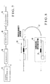
- Fig. 6 is a view showing an outlined configuration of a sixth embodiment of the present invention.
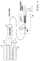
- Fig. 7 is a view showing an outlined configuration of a seventh embodiment of the present invention.
- Fig. 8 is a view showing an outlined configuration of an eighth embodiment of the present invention.
- Fig. 9 is a view showing a relationship between an amount of displacement and an amount of shift of a reflected wavelength in the fifth embodiment of the present invention.
- Fig. 10 is a view showing a temperature compensation effect of an amount of displacement in the eighth embodiment shown in Fig. 8;
- Fig. 11 is a view showing an outlined configuration of an optical fiber sensor according to a ninth embodiment of the present invention.
- Fig. 12 is a view showing an outlined configuration of an optical fiber sensor according to a tenth embodiment of the present invention.
- Fig. 13 is a view showing an outlined configuration of an optical fiber sensor according to an eleventh embodiment of the present invention.
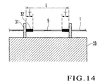
- Fig. 14 is a view to explain a principle of an optical fiber sensor with a temperature compensation function
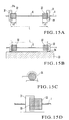
- Fig. 15A, 15B and 15C are a plan view, front view and side view of an optical fiber sensor with a temperature compensation function according to a twelfth embodiment of the present invention respectively, and Fig. 15D is an enlarged view of a fixed part of a protrusion and a holder shown in Fig. 15B; and
- Fig. 16 is a partial cross-sectional view showing an outlined configuration of a conventional fiber type detection element.
- Fig. 1 shows an outlined configuration of an optical fiber sensor according to a first embodiment of the present invention.
- An optical fiber 1 in which a fiber Bragg grating 5 is written is coated with resin 2, which protects the optical fiber 1.
- the optical fiber 1 is adhered to fiber fixtures 4 and 6 as flat boards on both sides of the fiber Bragg grating (hereafter fiber grating) 5 via the resin 2 using an elastic adhesive 3, and the fixtures 4 and 6 are directly fixed to an object to be measured.
- optical fiber 1 it is also possible to fix the optical fiber 1 to the fixtures 4 and 6 using the resin 2 instead of the elastic adhesive 3. Furthermore, it is also possible to use clamp fixing instead of the elastic adhesive 3. Furthermore, it is also possible to coat the optical fiber 1 with electroless plating or electrolytic plating at both ends of the fiber Bragg grating 5 instead of the resin 2. In this case, the optical fiber 1 can also be fixed to the fixtures 4 and 6 with electroless plating or electrolytic plating.
- ⁇ an amount of shift of a peak wavelength of the reflected light from the fiber Bragg grating 5 (or peak wavelength of the spectral dip of the light passing through the fiber Bragg grating 5) is ⁇ , then expression (1) is established.
- ⁇ is a constant related to the structure, etc. of the fiber Bragg grating 5 and is a wavelength- strain coefficient.
- ⁇ ⁇ * ⁇
- the strain ⁇ is calculated from expression (1) by detecting the amount of shift ⁇ . From the calculated strain bE and the selected distance between the fixtures x1, the amount of expansion/contraction (amount of displacement/change from the object to be measured) ⁇ x1 is calculated by using expression (2). From the amount of expansion/contraction ⁇ x1 calculated and known elastic modulus k1, the amount of variation ⁇ F0 is obtained by using expression (3).
- the wavelength resolution ⁇ is determined by the performance of the measuring instrument and since the wavelength- strain constant ⁇ and elastic modulus k1 are known, it is understood that the displacement resolution ⁇ x1 decreases as the distance between the fixtures x1 decreases.
- the wavelength- strain constant ⁇ is known, it is understood that the greater the distance between the fixtures x1 and wavelength detection width ⁇ MAX ⁇ , the greater the displacement detection width ⁇ MAX x1 is. That is, it is understood that it is possible to freely select the resolution and detection width of the amount of displacement of an object to be measured by adjusting the fixture distance x1.
- thermo-setting type polyimide resin is used, for example.
- polyimide resin can improve thermal resistance and abrasion resistance and this resin shows high tensile strength and high elasticity compared to other resin.
- thermo-setting type fluororesin phenol resin can improve chemical resistance and watertightness. It is also possible to use 2-liquid mixed room temperature setting type epoxy resin or polyester resin. These are excellent in long-term stability.
- Fig. 2 shows an outlined configuration of an optical fiber sensor according to a second embodiment of the present invention.
- the same components as those in the first embodiment in Fig. 1 are assigned the same reference numerals.
- the second embodiment differs from the first embodiment in that the fixture 6 is not directly fixed to an object to be measured, but indirectly fixed to the object via a spring 7.
- the elastic modulus of the optical fiber that is, the fiber Bragg grating 5
- the spring modulus of the spring 7 is k2 (selectable)
- the amount of displacement of the object to be measured is ⁇ x0
- the amount of expansion/contraction (more specifically, amount of expansion/contraction of fixture distance x1) of the optical fiber, that is, fiber Bragg grating 5 is ⁇ x1
- the amount of expansion/contraction of the spring is ⁇ x2
- the amount of variation of force F0 such as weight, pressure and acceleration applied to the object to be measured
- the amount of expansion/contraction ⁇ x1 calculated from expression (1) and expression (2), the known elastic modulus k1 and the selected spring modulus k2, the amount of variation of force ⁇ F0 and amount of expansion/contraction ⁇ x2 are calculated by using expression (8). Furthermore, from the calculated amounts of expansion/contraction ⁇ x1, ⁇ x2, the amount of displacement ⁇ x0 is calculated by using expression (9).
- the resolution ⁇ x1 and detection width ⁇ MAX x1 are determined.
- the wavelength- strain constant ⁇ is known, it is understood that if the wavelength detection width ⁇ MAX ⁇ is increased and/or the spring modulus k2 is decreased without changing the fixture distance x1, the displacement detection width ⁇ MAX x0 increases. Therefore, selecting the spring constant k2 makes it possible to freely select the resolution and detection width of the amount of displacement.
- Fig. 3 shows an outlined configuration of an optical fiber sensor according to a third embodiment of the present invention.
- the third embodiment differs from the first embodiment in that the fixture 6 is not directly fixed to an object to be measured, but indirectly fixed to the object via a lever 8.
- Reference numeral 9 is a link that connects the lever 8 and fixture 6.
- the amount of variation of force ⁇ F1 is calculated from the amount of expansion/contraction ⁇ x1 calculated from expression (1) and expression (2) and the known elastic modulus k1 by using expression (12).
- the amount of variation of force ⁇ F0' is calculated from the calculated amount of variation of force ⁇ F1 and the selected lever ratio l1/l2 by using expression (13).
- the resolution of the amount of variation ⁇ of a bragg wavelength is ⁇
- the resolution of the amount of variation of force ⁇ F1 is ⁇ F1
- the following relationship is established between the resolution ⁇ x0' of the amount of displacement ⁇ x0' and the resolution ⁇ F0' of force ⁇ F0' :
- selecting the lever ratio 11/12 makes it possible to expand/contract the amount of expansion/contraction ⁇ x1. Because of this, it is possible to expand the measurement range of displacement ⁇ x0' through measurement of the amount of expansion/contraction ⁇ x1. That is, selecting the lever ratio 11/12 can adjust the sensitivity.
- Fig. 4 shows an outlined configuration of an optical fiber sensor according to a fourth embodiment of the present invention.
- the fourth embodiment is implemented by adding a lever to the second embodiment, in other words, by adding a spring to the third embodiment. That is, the fixture 6 is not directly fixed to an object to be measured, but indirectly fixed to the object via the lever 8 and spring 7.
- the lever 8 and fixture 6 are connected by a link 9.
- the amount of variation ⁇ F0' can be calculated by using expressions (1), (2), (12) and (13). From the calculated amount of variation of force ⁇ F0' and spring constant k2, the amount of displacement ⁇ x0" is calculated by using expression (24).
- detection width ⁇ MAX F0' increases as the lever ratio 11/12 and/or ⁇ MAX ⁇ increases, and the detection width ⁇ MAX F0' increases as the spring constant k2 decreases.
- selecting the spring constant k2 and lever ratio 11/12 makes it possible to freely select the resolution and detection width of a physical quantity such as displacement, weight, pressure, acceleration, etc.
- ⁇ x0" (k1/k2)*(11/12)* ⁇ x1 and therefore it is possible to expand/contract an amount of expansion/contraction ⁇ x1 by selecting the spring constant k2 and lever ratio 11/12 even if the amount of displacement ⁇ x0" is considerably large or considerably small. For this reason, it is possible to expand the range of measurement of displacement ⁇ x0" by means of measuring the amount of expansion/contraction ⁇ x1. That is, it is possible to adjust sensitivity by selecting the spring constant k2 and lever ratio 11/12.
- Fig. 5 shows an outlined configuration of a fifth embodiment of the present invention.
- This embodiment shows an example of a system applying the optical fiber sensor shown in Fig. 2 to an FBG wavelength shift detection apparatus using a broadbandlight source and a wavelength detector.
- the FBG sensing element 10 configured by the optical fiber sensor (substantially a strain detection section) shown in Fig. 2 is connected to an optical fiber 11 and further connected via an optical coupler 12 to a broadbandlight source 13 made up of a light-emitting diode, etc. and a wave-meter or optical spectral analyzer (OSA) 14 made up of an optical spectrum analyzer.
- OSA optical spectral analyzer
- the light emitted from the broadbandlight source 13 is led through the optical coupler 12 and optical fiber 11 to the FBG sensing element 10.
- the light emitted from the broadband light source 13 contains light beams with wavelengths covering a wide band, but normally the reflected light of a wavelength ⁇ B is detected through the optical coupler 12 by the wave-meter or optical spectral analyser (OSA) 14. This is because the fiber Bragg grating 5 at the FBG sensing element 10 only bragg-reflects the light of a specific wavelength ⁇ B determined by the grating period, index of refraction, etc.
- the incident light to the optical fiber behind the FBG sensing element 10 has a dip at the position of the wavelength ⁇ B.
- selecting the spring constant k2 and/or lever ratio 11/12 as appropriate makes it possible to freely select the resolution and detection width of a physical quantity such as displacement, weight, pressure, and acceleration. Moreover, even if displacement ⁇ x0 is large, it is possible to reduce the amount of expansion/contraction ⁇ x1 to be measured by selecting the spring constant k2, and thus it is possible to expand the range of measurement of the amount of displacement ⁇ x0. It is also possible to use an optical circulator instead of the optical coupler 12.
- Fig. 6 shows an outlined configuration according to a sixth embodiment of the present invention.
- the sixth embodiment shows an example of applying an optical fiber sensor to a wavelength tracking system, "Fiber Bragg Grating Interrogation System (FBG-IS)".
- FBG-IS Fiber Bragg Grating Interrogation System
- This embodiment differs from the fifth embodiment in that a light source system and light detection system are systematized in FBG-IS 18.
- the light emitted from a broadband light source 13 is introduced through a coupler 12 and optical fiber 11 to an FBG detection section (optical fiber sensor in Fig. 2) 10 as in the case of Fig. 5 and the reflected light is detected via a wavelength tunable filter 16 of the light detection system by a photodetector 17.
- a reference light source 15 is used to correct a peak of a spectrum of the light reflected by the FBG sensing element 10, that is, value of Bragg wavelength, light of a plurality of wavelengths corrected with accuracy on the order of 1 pm is emitted from the reference light source 15.
- the light detection system switches between the light from this reference light source 15 and the reflected light from the FBG sensing element 10 that detects variations in a physical amount and detects wavelengths with high accuracy.
- the wavelength of the light detected by the wavelength tunable filter 16 in the light detection system normally fluctuates due to drift of the detected wavelength and disturbance of temperature, etc. but this reference light allows the wavelength to be corrected. Because of this, this embodiment allows more stable and accurate measurements than the fifth embodiment.
- Fig. 9 shows a relationship between the amount of displacement ⁇ x0 and amount of wavelength shift of the reflected light ⁇ measured by the fifth embodiment. It is apparent that the amount of wavelength shift of the reflected light ⁇ varies linearly with respect to the amount of displacement ⁇ x0. Furthermore, for the amount of displacement ⁇ x0, a wide range of measurement of 0 to 50 mm is possible. These measured values are temperature-compensated.
- Fig. 7 shows an outlined configuration according to a seventh embodiment of the present invention.
- the seventh embodiment comprises a plurality of FBG sensing elements 10 functioning as strain detection sections in which the fiber Bragg gratings 5 with different wavelengths of reflected light are written connected in series via an optical fiber 11 by means of fusion splicing, optical connector connection or mechanical splicing.
- FIG. 7 shows the case where a wavelength tracking system 108 made up of the FBG-IS explained in the sixth embodiment is applied to the light source and light detection system, but since the wavelength of the reflected light from each FBG detection section 10 forming the optical fiber sensor varies from one FBG detection section to another, allowing an optical measurement system made up of a single light source and single wavelength detector to detect at a plurality of FBG sensing elements 10. Furthermore, using FBG sensing elements 10 connected in series allows measurements from a plurality of sites simultaneously.
- optical fiber sensors connected in series similar to this embodiment can also be created by writing fiber Bragg gratings 5 with different wavelengths of reflected light at a plurality of locations of a single optical fiber.
- Fig. 8 shows an outlined configuration according to an eighth embodiment of the present invention.
- the eighth embodiment is implemented by adding a temperature compensation optical fiber sensor (FBG temperature detection section) 19 to the fifth embodiment containing the wave-meter or optical spectral analyzer (OSA) to enable temperature compensation.
- the temperature compensation optical fiber sensor 19 used is the one in which a fiber Bragg grating 25 is written with wavelength ⁇ T of reflected light different from that of the strain detection fiber Bragg grating 5 and is connected in series to a strain detection optical fiber sensor (FBG sensing element) 10 via an optical fiber 11.
- the wave-meter or optical spectral analyser (OSA) 14 can detect an amount of wavelength shift ⁇ of the FBG sensing element 10, an amount of wavelength shift ⁇ T* ⁇ T of the temperature detection section 19 ( ⁇ T is an amount of wavelength shift per unit temperature, ⁇ T is a temperature variation) independently.
- the FBG temperature detection section 19 has one end pasted and fixed to a material whose coefficient thermal linear expansion is known in such a way that it is never affected by changes in a physical quantity such as displacement, weight, pressure, acceleration and can detect only expansion/contraction by a temperature.
- This embodiment describes an example of application to the fifth embodiment, but temperature compensation is also applicable to other embodiments.
- temperature compensation is also applicable to other embodiments.
- a plurality of FBG sensing elements 10 are connected in series, too, even one temperature detection section 19 suffices if the fiber Bragg gratings 5 with different reflected wavelengths are used.
- Fig. 10 shows a temperature compensation effect with an amount of displacement ⁇ x0 measured by using this embodiment.
- an amount of displacement without temperature compensation black circle
- an amount of displacement with temperature compensation white squares
- Fig. 11 shows an outlined configuration of an optical fiber sensor according to a ninth embodiment of the present invention.
- the first to eighth embodiments describe the cases where variations in a physical quantity occur in an object to be measured in a certain direction, but this embodiment shows a case where an optical fiber sensor is applied to an object to be measured in which variations in a physical quantity occur in two directions.
- an optical fiber 1 is adhered to a pair of fixtures 4 and 6 using an elastic adhesive 3 on both sides of the optical fiber 1 in which the fiber Bragg grating 5 is written.
- Fig. 12 shows an outlined configuration of an optical fiber sensor according to a tenth embodiment of the present invention.
- This embodiment differs from the second embodiment in that variations in a physical quantity occur in an object to be measured in two directions, a pair of fixtures 4a and 6a are cylinder-shaped and a spring 7 is inserted between the fixtures 4a and 6a.
- the optical fiber 1 is placed on the fixtures 4a and 6a and on the central axis of the spring 7.
- Fig. 13 shows an outlined configuration of an optical fiber sensor according to an eleventh embodiment of the present invention. This embodiment differs from the third embodiment in that variations in a physical quantity occur in an object to be measured in two directions and levers 8 are connected to both fixtures 4 and 6 via a link 9.
- the eighth embodiment requires an FBG temperature detection section besides the PBG detection section, but it is also possible to provide a temperature compensation function for the optical fiber sensor itself.
- the temperature compensation method is a method of making an output value of the strain gauge or strain meter itself caused by a temperature variation almost the same as the amount of strain involved in free expansion of the object to be measured caused by a temperature variation (self temperature compensation gauge, temperature compensation type strain meter).
- the temperature compensation method using a free end will be detailed below.
- each part has:
- k in expression (36) is the strain sensitivity of the FBG optical fiber 1 and the unit is ( ⁇ 10 -6 /1 ⁇ 10 -6 ).
- ⁇ is known and ⁇ and k are calculated from a test. Therefore, it is possible to calculate 1( ⁇ ) by setting L and using ⁇ (1) as a variable.
- Fig. 15A to 15D show a twelfth embodiment of the present invention.
- a pair of cylindrical protrusions 32 made of acetal resin are adhered and fixed to the corresponding surfaces of a pair of disk-like holders 31 with a flange section 31a using an adhesive 34.
- An optical fiber 1 penetrates through the center of the holders 31 and protrusions 32 and are fixed.
- the holders 31 are adhered and fixed to the structure 33 using an adhesive 34 with the optical fiber 1 tensioned between the protrusions 32 with predetermined tension.
- the distance between the holders 31 is fixed.
- Between the flange section 31a of the holder 31 and the protrusion 32 is a space taking account of a difference between the linear expansion coefficient of the fixture and the linear expansion coefficient of the protrusion as shown in Fig. 15D.
- E ⁇ t + k . ( ⁇ . L - ⁇ . ⁇ ) L - ⁇ . t
- Length 1 of the protrusion 32 for temperature compensation is expressed by expression (46).
- the optical fiber sensor with a temperature compensation function can cancel apparent strain by only changing the length of the protrusions 32 according to the material (iron, aluminum, stainless steel, etc.) of the structure 33 whose strain is to be measured.
- the structure 33 is the object to be measured (when the fixture distance L is not fixed), it is possible to compensate temperatures by adjusting the length l of the protrusions 32, specifying the length of the fixture distance L and fixing the holders 31 to the object to be measured.
- the optical fiber in which a fiber grating is written includes a strain detection section in which the optical fiber on both sides of the fiber grating is fixed by fixtures and the fixtures are directly or indirectly fixed to the object to be measured. Displacement, weight, pressure or acceleration applied to the object to be measured is detected as an amount of shift of wavelength of the reflected light or transmitted light via expansion/contraction of the fiber grating, that is, strain . This makes it possible to accurately detect a physical quantity such as displacement, weight, pressure or acceleration applied to 2 points of the object to be measured taking advantage of a wide elastic area of the optical fiber.
- the optical fiber sensor of the present invention it is possible to detect a physical quantity such as displacement, weight, pressure and acceleration, etc. with high accuracy and high resolution by converting the physical quantity to an amount of expansion/contraction of the fiber grating taking advantage of the high elastic area of no less than 4% of the fiber Bragg grating. Furthermore, it is also possible to freely select and detect the sensitivity and resolution about the physical quantity such as displacement, weight, pressure or acceleration, etc.
- the optical sensor of the present invention provides protective coating at least both ends or covering the whole of the fiber Bragg grating with resin beforehand and attaches this coated fiber grating to fixtures. This makes it possible to prevent scars or micro cracks or reduce the probability of rupture before or when mounting the fiber grating. It is desirable to use as resin, thermo-setting polyimide resin, phenol resin, fluororesin or 2-liquid mixed room temperature setting type epoxy resin or polyester resin, which can improve thermal resistance, abrasion resistance, chemical resistance and watertightness etc.
- both ends of the fiber Bragg grating are adhered and fixed to the fixtures using an elastic adhesive or directly fixed to the fixtures by means of resin or mechanically clamped.
- the fixture can be anything whether a flat board, hardware made up of grooved round bar or square bar, part of a mechanism used for a spring, lever, etc. forming a sensor.
- the present invention is also applicable to a case where the fiber Bragg grating is directly fixed to an object to be measured by regarding part of the object to be measured as a fixture.
- the optical fiber sensor of the present invention provides protection at least at both ends or covering the whole of the fiber Bragg grating with electroless plating or electrolytic plating or both. This makes it possible to have effect similar to that of protection with resin.
- the fiber Bragg grating can also be fixed to the fixtures by means of electroless plating or electrolytic plating.
- the optical fiber sensor of the present invention detects displacement, weight, pressure or acceleration applied to the object to be measured as an amount of wavelength shift of reflected light or transmitted light by means of expansion/contraction of the fiber grating and can freely select detection resolution and detection width (scan width of parameters necessary for detection). As one way of this, it is possible to select resolution of the amount of displacement by adjusting the distance between two fixtures at both ends of the fiber grating (that is , adjusting the position of one fixture) and directly fixing the fiber grating to the object to be measured.
- the optical fiber sensor of the present invention indirectly fixes one fixture to the object to be measured by inserting a spring and/or lever between the fixture and object and makes it possible to freely select resolution and detection width of a physical quantity such as displacement, weight, pressure or acceleration to be detected by arbitrarily selecting a spring constant and/or lever ratio.
- the optical fiber sensor of the present invention comprises a plurality of strain detection sections in which fiber Bragg gratings with different reflected wavelengths are written in the optical fiber, connected in series via the optical fiber. This allows measurements from a plurality of sites to be performed simultaneously or collectively.
- the optical fiber sensor of the present invention includes a temperature detection section with the optical fiber in which a fiber Bragg grating with a reflected wavelength different from that of the strain detection section is written directly fixed to the fixture on one end of the fiber Bragg grating and freely fixed to the other end so as to be completely free of influences of changes of displacement, weight, pressure or acceleration and this temperature detection section is connected in series to the strain detection section via the optical fiber.
- the present invention provides temperature compensation by calculating and subtracting an amount of wavelength shift detected by the temperature detection section from the amount of wavelength shift detected by the strain detection section.
- Free fixing means such a condition that the fiber Bragg grating is physically fixed to a fixture, but completely free of influences of changes of displacement, weight, pressure or acceleration.
- a temperature detection section is proposed in the Japanese Patent Laid-Open No. 2000-111319.
- optical fiber sensor of the present invention allows measurements from a plurality of sites to be carried out simultaneously or collectively by using optical fiber sensors connected in series. Furthermore, using an optical fiber sensor capable of temperature compensation provides measurements of true physical quantities independent of temperature.
Abstract
Description
- The present invention relates to an optical fiber sensor for detecting a physical quantity of displacement, weight, pressure and acceleration, or the like.
- As disclosed in the Japanese Patent Laid-Open No. 2000-111319, the development of a strain sensor or temperature sensor using a fiber type detection element called "fiber Bragg grating (FBG)" is recently being carried forward.. These sensors take advantage of the fact that a grating (diffraction grating) is created in the traveling direction of the incident light and when the pitch of the grating written in an optical fiber is changed by strain or temperature, the peak wavelength of the light braggreflected from the grating changes according to the change or the spectrum of the light passing through the grating changes (the central wavelength of the dip light changes).
- Fig. 16 is a partial cross-sectional view showing a configuration of a conventional optical fiber sensor. In Fig. 16,
reference numeral 51 denotes an optical fiber core wire made up of anoptical fiber 52 such as a silica glass based optical fiber provided with acoating 53 of UV-cured epoxy acrylate, etc. Part of thecoating 53 of the opticalfiber core wire 51 is stripped over a length of 1 cm to 4 cm where the interior of theoptical fiber 52 is exposed. In the exposedoptical fiber 52, fiber Bragg grating (hereafter fiber grating) 54 is written and the surface thereof is provided with recoating 55 made of UV-cured epoxy acrylate. The reason that the recoating 55 made of UV-cured epoxy acrylate is used is that optical fiber core wires with a coating of UV-cured epoxy acrylate are widely used and it is easy to provide coating, etc. - In order to use this fiber grating 54 to detect physical quantities as an optical fiber sensor, it is conceivable to fix the part of the
fiber grating 54 to the detection location of an object to be measured using resin such as epoxy without peeling off the UV-cured epoxy acrylate coating. - However, most of the general UV-cured epoxy acrylate used here is of a low-resistant and creep-provoking material. Thus, if the coated UV-cured epoxy acrylate is pasted to the detection location, the resin itself would provoke creep, preventing a physical quantity such as displacement, weight, pressure, or acceleration from being directly converted to expansion/contraction of a fiber grating, that is, strain , causing a problem of reducing the accuracy of detecting physical quantities.
- As alternative means, without recoating the fiber grating 54, or by removing the recoating part again with the
optical fiber 52 exposed, the part of the fiber Bragggrating 54 is pushed against the detection location of the object to be measured and adhered and fixed thereto using resin such as epoxy. However, stripping theoptical fiber 52 of the UN-hardened resin, exposing quartz glass, which is the material of theoptical fiber 52, and pasting it to the detection location would produce a problem of causing scars and micro cracks on the quartz glass and increasing the probability of rupturing theoptical fiber 52. - On the other hand, it is also conceivable to use the
coating 55 made of thermo-setting resin for recoating . Using thermo-setting resin as the recoating material of the surface of theoptical fiber 52 in which thegrating 54 is written makes it possible to improve heat resistance and abrasion resistance, etc. This can solve the problem that resin itself will provoke creep, reducing the accuracy of detecting physical quantities or the problem of increasing the probability of rupturing the optical fiber. - However, handling the fiber Bragg grating as the optical fiber sensor involves the following problems:
- (1) When the fiber Bragg grating part is directly pasted to a material such as metal, the range of elastic deformation is dominated by the metal content that is on the order of 0.3%, making it impossible to use the high elastic area of the optical fiber that is no less than 4%.
- (2) It is not possible to freely select the sensitivity and resolution of a physical quantity such as weight, displacement, pressure and acceleration.
- (3) An effect due to temperature is a problem in measuring the physical quantity so that it will become a noise factor in measuring a physical quantity.
-
- It is an object of the present invention to provide an optical fiber sensor using a fiber grating capable of detecting a physical quantity such as displacement, weight, pressure and acceleration with high accuracy and high sensitivity by using the high elasticity of the optical fiber.
- It is another object of the present invention to provide an optical fiber sensor using a fiber Bragg grating capable of freely selecting the sensitivity and resolution of a physical quantity.
- It is another object of the present invention to provide an optical fiber sensor using a fiber Bragg grating capable of compensating temperature.
- In order to attain the above objects, the present invention provides an optical fiber sensor comprising an optical fiber, a first fiber Bragg grating written in the optical fiber, a pair of fixtures fixed to the optical fiber on both sides of the first fiber Bragg grating, which are fixed to an object to be measured, characterized in that displacement, weight, pressure or acceleration applied to the object to be measured is output as an amount of shift of the wavelength of one of the reflected light or transmitted light through expansion/contraction of the first fiber Bragg grating above.
- Fig. 1 is a view showing an outlined configuration of an optical fiber sensor according to a first embodiment of the present invention;
- Fig. 2 is a view showing an outlined configuration of an optical fiber sensor according to a second embodiment of the present invention;
- Fig. 3 is a view showing an outlined configuration of an optical fiber sensor according to a third embodiment of the present invention;
- Fig. 4 is a view showing an outlined configuration of an optical fiber sensor according to a fourth embodiment of the present invention;
- Fig. 5 is a view showing an outlined configuration of a fifth embodiment of the present invention;
- Fig. 6 is a view showing an outlined configuration of a sixth embodiment of the present invention;
- Fig. 7 is a view showing an outlined configuration of a seventh embodiment of the present invention;
- Fig. 8 is a view showing an outlined configuration of an eighth embodiment of the present invention;
- Fig. 9 is a view showing a relationship between an amount of displacement and an amount of shift of a reflected wavelength in the fifth embodiment of the present invention;
- Fig. 10 is a view showing a temperature compensation effect of an amount of displacement in the eighth embodiment shown in Fig. 8;
- Fig. 11 is a view showing an outlined configuration of an optical fiber sensor according to a ninth embodiment of the present invention;
- Fig. 12 is a view showing an outlined configuration of an optical fiber sensor according to a tenth embodiment of the present invention;
- Fig. 13 is a view showing an outlined configuration of an optical fiber sensor according to an eleventh embodiment of the present invention;
- Fig. 14 is a view to explain a principle of an optical fiber sensor with a temperature compensation function;
- Fig. 15A, 15B and 15C are a plan view, front view and side view of an optical fiber sensor with a temperature compensation function according to a twelfth embodiment of the present invention respectively, and Fig. 15D is an enlarged view of a fixed part of a protrusion and a holder shown in Fig. 15B; and
- Fig. 16 is a partial cross-sectional view showing an outlined configuration of a conventional fiber type detection element.
- With reference now to the attached drawings, embodiments of the present invention will be explained in detail below.
- Fig. 1 shows an outlined configuration of an optical fiber sensor according to a first embodiment of the present invention. An optical fiber 1 in which a fiber Bragg
grating 5 is written is coated withresin 2, which protects the optical fiber 1. The optical fiber 1 is adhered tofiber fixtures resin 2 using anelastic adhesive 3, and thefixtures - It is also possible to fix the optical fiber 1 to the
fixtures resin 2 instead of theelastic adhesive 3. Furthermore, it is also possible to use clamp fixing instead of theelastic adhesive 3. Furthermore, it is also possible to coat the optical fiber 1 with electroless plating or electrolytic plating at both ends of the fiber Bragg grating 5 instead of theresin 2. In this case, the optical fiber 1 can also be fixed to thefixtures - This makes it possible to measure a physical quantity such as displacement, weight, pressure and acceleration applied to an object to be measured through an amount of expansion/contraction of the fiber Bragg grating 5 as an amount of wavelength shift of the bragg reflected light from the
fiber grating 5 or a peak variatio in the spectral dip of the light passing through the fiber Bragggrating 5, that is, an amount of wavelength shift. Since the part of thefiber grating 5 is not adhered to thefixtures - Suppose the strain of the
fiber grating 5 is δε, an amount of shift of a peak wavelength of the reflected light from the fiber Bragg grating 5 (or peak wavelength of the spectral dip of the light passing through the fiber Bragg grating 5) is δλ, then expression (1) is established. ω is a constant related to the structure, etc. of the fiber Bragg grating 5 and is a wavelength- strain coefficient. - On the other hand, suppose the elastic modulus of the optical fiber in which the fiber Bragg
grating 5 is written is k1, the distance between the fixtures on both sides of the fiber Bragg grating 5 (hereinafter referred to as "fixture distance") is x1, an amount of expansion/contraction of the distance between the fixtures x1 (substantially the amount of expansion/contraction of the optical fiber) is δx1, an amount of variation of force F0 applied to the object to be measured such as weight, pressure and acceleration is δF0, then expression (2) and expression (3) are established. - Since the wavelength- strain coefficient ω is known, if the amount of shift δλ is detected, the strain δε is calculated from expression (1) by detecting the amount of shift δλ. From the calculated strain bE and the selected distance between the fixtures x1, the amount of expansion/contraction (amount of displacement/change from the object to be measured) δx1 is calculated by using expression (2). From the amount of expansion/contraction δx1 calculated and known elastic modulus k1, the amount of variation δF0 is obtained by using expression (3).
- Here, it is possible to selectively determine the resolution and detection width of the amount of displacement of the object to be measured by adjusting the distance between the fixtures x1. Suppose the wavelength resolution is Δδλ, strain resolution is Δδε, displacement resolution of the amount of expansion/contraction δx1 is Δδx1, then expressions (4) and (5) are established.
- The wavelength resolution Δδλ is determined by the performance of the measuring instrument and since the wavelength- strain constant ω and elastic modulus k1 are known, it is understood that the displacement resolution Δδx1 decreases as the distance between the fixtures x1 decreases.
- Furthermore, regarding the detection width, suppose the wavelength detection width is δMAXλ, strain detection width is δMAXε, displacement detection width of δx1 is δMAXx1, then expressions (6) and (7) are established.
- Since the wavelength- strain constant ω is known, it is understood that the greater the distance between the fixtures x1 and wavelength detection width δMAXλ, the greater the displacement detection width ΔδMAXx1 is. That is, it is understood that it is possible to freely select the resolution and detection width of the amount of displacement of an object to be measured by adjusting the fixture distance x1.
- Regarding resin, thermo-setting type polyimide resin is used, for example. Using polyimide resin can improve thermal resistance and abrasion resistance and this resin shows high tensile strength and high elasticity compared to other resin. Furthermore, using thermo-setting type fluororesin, phenol resin can improve chemical resistance and watertightness. It is also possible to use 2-liquid mixed room temperature setting type epoxy resin or polyester resin. These are excellent in long-term stability.
- Fig. 2 shows an outlined configuration of an optical fiber sensor according to a second embodiment of the present invention. The same components as those in the first embodiment in Fig. 1 are assigned the same reference numerals. The second embodiment differs from the first embodiment in that the
fixture 6 is not directly fixed to an object to be measured, but indirectly fixed to the object via aspring 7. - Suppose the elastic modulus of the optical fiber, that is, the fiber Bragg grating 5 is k1, the spring modulus of the
spring 7 is k2 (selectable), the amount of displacement of the object to be measured is δx0, the amount of expansion/contraction (more specifically, amount of expansion/contraction of fixture distance x1) of the optical fiber, that is, fiber Bragg grating 5 is δx1, the amount of expansion/contraction of the spring is δx2, the amount of variation of force F0 such as weight, pressure and acceleration applied to the object to be measured is δF0, then the following expressions are established: - As described above, from the amount of expansion/contraction δx1 calculated from expression (1) and expression (2), the known elastic modulus k1 and the selected spring modulus k2, the amount of variation of force δF0 and amount of expansion/contraction δx2 are calculated by using expression (8). Furthermore, from the calculated amounts of expansion/contraction δx1, δx2, the amount of displacement δx0 is calculated by using expression (9).
- In the case of the first embodiment, when the fixture distance x1 is selected, the resolution Δδx1 and detection width δMAXx1 are determined. Here, it is possible to select a spring modulus k2 and selectively determine the resolutionΔδx0 of the displacement and detection width δMAXx0 of the object to be measured. That is, suppose strain resolution is Δδε, resolution of the amount of expansion/contraction of δx1 and δx2 is Δδx1 and Δδx2, then the displacement resolution Δδx0 of the object to be measured is as follows:
- Since the wavelength resolution Δδλ, wavelengthstrain constant ω and elastic modulus k1 of the optical fiber are known, it is possible to reduce Δδx0 by increasing the spring modulus k2 without changing the fixture distance x1.
- On the other hand, regarding the detection width, suppose the wavelength detection width is δMAXλ, strain detection width is δMAXε, displacement detection widths of δx1 and δx2 are δMAXx1 and δMAXx2, then the displacement detection widthδMAXx0 of the object to be measured is as follows:
- Since the wavelength- strain constant ω is known, it is understood that if the wavelength detection width δMAXλ is increased and/or the spring modulus k2 is decreased without changing the fixture distance x1, the displacement detection width δMAXx0 increases. Therefore, selecting the spring constant k2 makes it possible to freely select the resolution and detection width of the amount of displacement.
- Fig. 3 shows an outlined configuration of an optical fiber sensor according to a third embodiment of the present invention. The third embodiment differs from the first embodiment in that the
fixture 6 is not directly fixed to an object to be measured, but indirectly fixed to the object via alever 8.Reference numeral 9 is a link that connects thelever 8 andfixture 6. - Suppose an amount of variation of force F1 applied to the fiber Bragg grating 5 is δF1, strain is δε, wavelengthstrain coefficient is ω, the length from the fulcrum of the
lever 8 to thefixture 6 is 11, the amount of variation of force F0' by the weight, pressure and acceleration applied to the object to be measured, that is , the point of application is δF0', the length from the fulcrum of thelever 8 to the point of application is 12, the amount of expansion/contraction of the fiber Bragg grating is δx1, the amount of displacement of the object to be measured is δx0', then the following relation is established: - As described above, the amount of variation of force δF1 is calculated from the amount of expansion/contraction δx1 calculated from expression (1) and expression (2) and the known elastic modulus k1 by using expression (12). The amount of variation of force δF0' is calculated from the calculated amount of variation of force δF1 and the selected lever ratio l1/l2 by using expression (13). Moreover, the amount of displacement δx0' of the object to be measured from the calculated amount of expansion/contraction δx1 and the selected
lever ratio 11/12 by using expression (14).
That is, - From expression (18) to expression (20), it is understood that as the
lever ratio 11/12 increases, the resolution Δδx0' improves, and as thelever ratio 11/12 reduces, the resolution ΔδF0' improves. - Furthermore, regarding a detection width, suppose the wavelength detection width is δMAXλ, the weight detection width of force δF1 is δMAXF1, then the following relationship is established between the detection width δMAXx0' of the amount of displacement δx0' and the detection width δMAXF0' of force δF0':
- From expression (21) to expression (23), it is understood that as the
lever ratio 11/12 and δMAXλ increase, the detection width δMAXF0' increases, and as thelever ratio 11/12 decreases and/or δMAXλ increases, the detection width δMAXx0' increases. Thus, it is possible to freely select the resolution and the detection width of a physical quantity such as displacement, weight, pressure and acceleration by selecting thelever ratio 11/12. - Furthermore, from expression (14), even if displacementδx0' is considerably large or small, selecting the
lever ratio 11/12 makes it possible to expand/contract the amount of expansion/contraction δx1. Because of this, it is possible to expand the measurement range of displacement δx0' through measurement of the amount of expansion/contraction δx1. That is, selecting thelever ratio 11/12 can adjust the sensitivity. - Fig. 4 shows an outlined configuration of an optical fiber sensor according to a fourth embodiment of the present invention. The fourth embodiment is implemented by adding a lever to the second embodiment, in other words, by adding a spring to the third embodiment. That is, the
fixture 6 is not directly fixed to an object to be measured, but indirectly fixed to the object via thelever 8 andspring 7. Thelever 8 andfixture 6 are connected by alink 9. - Suppose a force applied to the fiber Bragg grating 5 is F1, the length from the fulcrum of the lever to the
fixture 6 is 11, the length from the fulcrum of the lever to the point of application (point of connection with the spring 7) of the force F0' is 12, an amount of expansion/contraction of the fiber Bragg grating 5 is δx1 and an amount of displacement of the object to be measured is δx0", then the following relationship is established: - As described above, the amount of variation δF0' can be calculated by using expressions (1), (2), (12) and (13). From the calculated amount of variation of force δF0' and spring constant k2, the amount of displacement δx0" is calculated by using expression (24).
- Furthermore, the following relationship is established between the resolution Δδx1 of the amount of expansion/contraction δx1, the resolution Δδx0" of the amount of displacement δx0" and the resolution Δδλ of the amount of wavelength shift δλ and the resolution ΔδF1 and ΔδF0' of the amounts of variation of force δF1 and δF0':
- From expression (19), it is understood that the resolution ΔδF0' improves as the
lever ratio 11/12 decreases and from expression (25), it is understood that the resolution Δδx0" improves as the spring constant k2 increases. - On the other hand, regarding the detection width, suppose the wavelength detection width is δMAXλ, weight detection width of δF1 is δMAXF1, then the following relationship is established between detection width δMAXx0" of an amount of displacement δx0" and detection width δMAXF0' of force δF0':
- From expression (26) to expression (28), it is understood that detection width δMAXF0' increases as the
lever ratio 11/12 and/or δMAXλ increases, and the detection width δMAXF0' increases as the spring constant k2 decreases. Thus, selecting the spring constant k2 andlever ratio 11/12 makes it possible to freely select the resolution and detection width of a physical quantity such as displacement, weight, pressure, acceleration, etc. - Furthermore, from expressions (12), (13) and (24),
lever ratio 11/12 even if the amount of displacement δx0" is considerably large or considerably small. For this reason, it is possible to expand the range of measurement of displacement δx0" by means of measuring the amount of expansion/contraction δx1. That is, it is possible to adjust sensitivity by selecting the spring constant k2 andlever ratio 11/12. - Fig. 5 shows an outlined configuration of a fifth embodiment of the present invention. This embodiment shows an example of a system applying the optical fiber sensor shown in Fig. 2 to an FBG wavelength shift detection apparatus using a broadbandlight source and a wavelength detector. The
FBG sensing element 10 configured by the optical fiber sensor (substantially a strain detection section) shown in Fig. 2 is connected to anoptical fiber 11 and further connected via anoptical coupler 12 to abroadbandlight source 13 made up of a light-emitting diode, etc. and a wave-meter or optical spectral analyzer (OSA) 14 made up of an optical spectrum analyzer. - The light emitted from the
broadbandlight source 13 is led through theoptical coupler 12 andoptical fiber 11 to theFBG sensing element 10. The light emitted from thebroadband light source 13 contains light beams with wavelengths covering a wide band, but normally the reflected light of a wavelength λB is detected through theoptical coupler 12 by the wave-meter or optical spectral analyser (OSA) 14. This is because the fiber Bragg grating 5 at theFBG sensing element 10 only bragg-reflects the light of a specific wavelength λB determined by the grating period, index of refraction, etc. On the other hand, the incident light to the optical fiber behind theFBG sensing element 10 has a dip at the position of the wavelength λB. - The
FBG sensing element 10 is fixed to an object to be measured as described above and when a physical quantity such as displacement, weight, pressure and acceleration changes, displacement occurs in the fiber Bragg grating 5, changing the wavelength of the reflected light from λB to λB'. At this time, the dip position of the incident light to the optical fiber cable behind also changes to λB'. Measuring the amount of this shift of wavelength δλ =λB'-λB makes it possible to measure displacement of the fiber Bragg grating 5, amount of displacement δx0 and a amount of variation of force δF0 such as weight, pressure or acceleration applied to the object to be measured. - Furthermore, as described above, selecting the spring constant k2 and/or
lever ratio 11/12 as appropriate makes it possible to freely select the resolution and detection width of a physical quantity such as displacement, weight, pressure, and acceleration. Moreover, even if displacement δx0 is large, it is possible to reduce the amount of expansion/contraction δx1 to be measured by selecting the spring constant k2, and thus it is possible to expand the range of measurement of the amount of displacement δx0. It is also possible to use an optical circulator instead of theoptical coupler 12. - Fig. 6 shows an outlined configuration according to a sixth embodiment of the present invention. The sixth embodiment shows an example of applying an optical fiber sensor to a wavelength tracking system, "Fiber Bragg Grating Interrogation System (FBG-IS)". This embodiment differs from the fifth embodiment in that a light source system and light detection system are systematized in FBG-
IS 18. - The light emitted from a
broadband light source 13 is introduced through acoupler 12 andoptical fiber 11 to an FBG detection section (optical fiber sensor in Fig. 2) 10 as in the case of Fig. 5 and the reflected light is detected via a wavelengthtunable filter 16 of the light detection system by aphotodetector 17. Areference light source 15 is used to correct a peak of a spectrum of the light reflected by theFBG sensing element 10, that is, value of Bragg wavelength, light of a plurality of wavelengths corrected with accuracy on the order of 1 pm is emitted from thereference light source 15. - The light detection system switches between the light from this
reference light source 15 and the reflected light from theFBG sensing element 10 that detects variations in a physical amount and detects wavelengths with high accuracy. The wavelength of the light detected by the wavelengthtunable filter 16 in the light detection system normally fluctuates due to drift of the detected wavelength and disturbance of temperature, etc. but this reference light allows the wavelength to be corrected. Because of this, this embodiment allows more stable and accurate measurements than the fifth embodiment. - Fig. 9 shows a relationship between the amount of displacement δx0 and amount of wavelength shift of the reflected light δλ measured by the fifth embodiment. It is apparent that the amount of wavelength shift of the reflected light δλ varies linearly with respect to the amount of displacement δx0. Furthermore, for the amount of displacement δx0, a wide range of measurement of 0 to 50 mm is possible. These measured values are temperature-compensated.
- Fig. 7 shows an outlined configuration according to a seventh embodiment of the present invention. The seventh embodiment comprises a plurality of
FBG sensing elements 10 functioning as strain detection sections in which thefiber Bragg gratings 5 with different wavelengths of reflected light are written connected in series via anoptical fiber 11 by means of fusion splicing, optical connector connection or mechanical splicing. Fig. 7 shows the case where a wavelength tracking system 108 made up of the FBG-IS explained in the sixth embodiment is applied to the light source and light detection system, but since the wavelength of the reflected light from eachFBG detection section 10 forming the optical fiber sensor varies from one FBG detection section to another, allowing an optical measurement system made up of a single light source and single wavelength detector to detect at a plurality ofFBG sensing elements 10. Furthermore, usingFBG sensing elements 10 connected in series allows measurements from a plurality of sites simultaneously. - By the way, optical fiber sensors connected in series similar to this embodiment can also be created by writing
fiber Bragg gratings 5 with different wavelengths of reflected light at a plurality of locations of a single optical fiber. - Fig. 8 shows an outlined configuration according to an eighth embodiment of the present invention. The eighth embodiment is implemented by adding a temperature compensation optical fiber sensor (FBG temperature detection section) 19 to the fifth embodiment containing the wave-meter or optical spectral analyzer (OSA) to enable temperature compensation. The temperature compensation
optical fiber sensor 19 used is the one in which a fiber Bragg grating 25 is written with wavelength λT of reflected light different from that of the strain detection fiber Bragg grating 5 and is connected in series to a strain detection optical fiber sensor (FBG sensing element) 10 via anoptical fiber 11. - Having a different reflected wavelength, the wave-meter or optical spectral analyser (OSA) 14 (Fig.5) can detect an amount of wavelength shift δλ of the
FBG sensing element 10, an amount of wavelength shift δλT*δT of the temperature detection section 19 (δλT is an amount of wavelength shift per unit temperature, δT is a temperature variation) independently. The FBGtemperature detection section 19 has one end pasted and fixed to a material whose coefficient thermal linear expansion is known in such a way that it is never affected by changes in a physical quantity such as displacement, weight, pressure, acceleration and can detect only expansion/contraction by a temperature. - It is possible to calculate a true amount of variation of reflected light δΛ independent of a temperature by theoretically subtracting the amount of wavelength shift δλT*δT of the
temperature detection section 19 from the amount of wavelength shift δλ of theFBG detection section 10 detected by the wavelength detector. Suppose the coefficient of linear expansion of the material at thetemperature detection section 19 is αB and the amount of wavelength variation per unit temperature corresponding to the variation of the index of refraction by temperature of the fiber grating is An, then the relationship between δλ, δλT and δΛ is expressed in expressions (30) and (31). - This embodiment describes an example of application to the fifth embodiment, but temperature compensation is also applicable to other embodiments. In a system in which a plurality of
FBG sensing elements 10 are connected in series, too, even onetemperature detection section 19 suffices if thefiber Bragg gratings 5 with different reflected wavelengths are used. - Fig. 10 shows a temperature compensation effect with an amount of displacement δx0 measured by using this embodiment. In Fig. 10, an amount of displacement without temperature compensation (black circle) and an amount of displacement with temperature compensation (white squares) are shown. It is understood that with 20°C as a reference point, large displacement of approximately 3 mm at -20°C and 60°C is compensated to approximately 0.3 mm.
- Fig. 11 shows an outlined configuration of an optical fiber sensor according to a ninth embodiment of the present invention. The first to eighth embodiments describe the cases where variations in a physical quantity occur in an object to be measured in a certain direction, but this embodiment shows a case where an optical fiber sensor is applied to an object to be measured in which variations in a physical quantity occur in two directions. In this embodiment, as in the case of the first embodiment, an optical fiber 1 is adhered to a pair of
fixtures elastic adhesive 3 on both sides of the optical fiber 1 in which the fiber Bragg grating 5 is written. - Fig. 12 shows an outlined configuration of an optical fiber sensor according to a tenth embodiment of the present invention. This embodiment differs from the second embodiment in that variations in a physical quantity occur in an object to be measured in two directions, a pair of
fixtures spring 7 is inserted between thefixtures fixtures spring 7. - Fig. 13 shows an outlined configuration of an optical fiber sensor according to an eleventh embodiment of the present invention. This embodiment differs from the third embodiment in that variations in a physical quantity occur in an object to be measured in two directions and
levers 8 are connected to bothfixtures link 9. - The eighth embodiment requires an FBG temperature detection section besides the PBG detection section, but it is also possible to provide a temperature compensation function for the optical fiber sensor itself.
- First, the principle of the optical fiber sensor with a temperature compensation function will be explained. As a method for measuring strain in structures at civil engineering or construction sites, a strain gauge or strain meter based on a strain gauge is used. Main strain that occurs in a structure is:
- 1) strain according to Hooke's law involved in a stress variation of the structure by an external force (hereinafter referred to as "effective strain "),
- 2) strain according to a liner expansion coefficient of a structure material involved in a temperature variation (hereinafter referred to as "apparent strain "), and these two kinds of strain act on a strain gauge or strain meter set in the structure in most cases.
-
- Here, for the purpose of knowing stress (external force) of a structure, effective strain must be calculated. Therefore, it is necessary to:
- I. Reduce the sensitivity of apparent strain of the strain gauge or strain meter (hereinafter referred to as "temperature compensation method")
- II. Separate and subtract apparent strain from measured values of the strain gauge and strain meter (hereinafter referred to as "temperature testing method").
-
- One of these methods is a temperature compensation method. The temperature compensation method is a method of making an output value of the strain gauge or strain meter itself caused by a temperature variation almost the same as the amount of strain involved in free expansion of the object to be measured caused by a temperature variation (self temperature compensation gauge, temperature compensation type strain meter). The temperature compensation method using a free end will be detailed below.
- As shown in Fig. 14, in a strain meter using an FBG in which a pair of
holders 31 having the same liner expansion coefficient as that of astructure 33 are connected to thestructure 33 in a distance L and an FBG optical fiber 1 is connected with certain tension toprotrusions 32 of the fixedmaterial 31, suppose L of thestructure 33 changes to L+ΔL due to temperature variation. (ΔL: apparent strain ). - Suppose each part has:
- Linear expansion coefficient of
structure 33 and holder 31: α(×10-6/°C) - Linear expansion coefficient of protrusion 31: β (×10-6/°C)
- Zero-point drift of FBG (including linear expansion
coefficient): γ(×10-6/°C)
and thestructure 33 is sufficiently rigid with respect to the FBG optical fiber 1. -
- In such a configuration, if the temperature at which L is expanded to L+ΔL is t(°C) is expressed as:
- Therefore,
- On the other hand, a variation of length ℓ of each protrusion 32: Δℓ/2 is:
- From above, when a temperature variation t(°C) acts on the
structure 33, the distance between theprotrusions 32 is expanded by: - Here, substituting expressions (33) and (34) into expression (35) results in:
- That is, when the
structure 33 expands by ΔL, the FBG optical fiber 1 is given forced displacement by (αL-βℓ)t. Therefore, temperature compensation of the strain meter requires the following expression to be satisfied: - Here, k in expression (36) is the strain sensitivity of the FBG optical fiber 1 and the unit is (×10-6/1×10-6). Here, α is known and γ and k are calculated from a test. Therefore, it is possible to calculate 1(β) by setting L and using β(1) as a variable.
- As an example, by dividing the left side of expression (37) by L, the following expression is obtained:
- Then, the above-described optical fiber sensor with a temperature compensation function will be explained more specifically. Fig. 15A to 15D show a twelfth embodiment of the present invention.
- As shown in Fig. 15A to 15C, a pair of
cylindrical protrusions 32 made of acetal resin are adhered and fixed to the corresponding surfaces of a pair of disk-like holders 31 with aflange section 31a using an adhesive 34. An optical fiber 1 penetrates through the center of theholders 31 andprotrusions 32 and are fixed. Theholders 31 are adhered and fixed to thestructure 33 using an adhesive 34 with the optical fiber 1 tensioned between theprotrusions 32 with predetermined tension. The distance between theholders 31 is fixed. Between theflange section 31a of theholder 31 and theprotrusion 32 is a space taking account of a difference between the linear expansion coefficient of the fixture and the linear expansion coefficient of the protrusion as shown in Fig. 15D. - In such a configuration, the output calculated value E is expressed in expression (41).
- To reduce the above apparent strain to zero,
- Now, because of a condition t ≠ 0,
- Length 1 of the
protrusion 32 for temperature compensation is expressed by expression (46). - Where:
- E: Output calculated value (×10-6/°C)
- α: Structure linear expansion coefficient (×10-6/°C) For example, Iron: 11.7
- γ: FBG zero drift = 8 (×10-6/°C)
- k: strain sensitivity = 1 (×10-6/1×10-6)
- β: Protrusion linear expansion coefficient = 85(×10-6/°C) (epoxy resin based adhesive, Delrin)
-
- Therefore, by specifying the material of the
structure 33, it is possible to calculate the length of theprotrusion 32 when the distance between the holders 31 L = 65 mm. - As described above, the optical fiber sensor with a temperature compensation function can cancel apparent strain by only changing the length of the
protrusions 32 according to the material (iron, aluminum, stainless steel, etc.) of thestructure 33 whose strain is to be measured. - The condition in that case should be as follows: Since in expression (43), γ is positive (FBG zero drift), k is positive ( strain sensitivity), (α·L-β·ℓ) must be negative. Therefore, α·L<β·ℓ.
- If the
structure 33 is the object to be measured (when the fixture distance L is not fixed), it is possible to compensate temperatures by adjusting the length ℓ of theprotrusions 32, specifying the length of the fixture distance L and fixing theholders 31 to the object to be measured. - As described above, in the optical fiber sensor according to the present invention, the optical fiber in which a fiber grating is written includes a strain detection section in which the optical fiber on both sides of the fiber grating is fixed by fixtures and the fixtures are directly or indirectly fixed to the object to be measured. Displacement, weight, pressure or acceleration applied to the object to be measured is detected as an amount of shift of wavelength of the reflected light or transmitted light via expansion/contraction of the fiber grating, that is, strain . This makes it possible to accurately detect a physical quantity such as displacement, weight, pressure or acceleration applied to 2 points of the object to be measured taking advantage of a wide elastic area of the optical fiber.
- There is nothing that touches the fiber grating and a variation in a physical quantity such as displacement, weight, pressure or acceleration applied to the object to be measured is converted to a variation of expansion/contraction applied to the optical fiber between the fixtures at both ends of the fiber grating and the fiber grating that forms the intermediate section is designed to be distorted uniformly. In this way, the optical fiber is directly strained and the strain amounts to no less than 4%, making it possible to use a wide elastic area.
- That is, according to the optical fiber sensor of the present invention, it is possible to detect a physical quantity such as displacement, weight, pressure and acceleration, etc. with high accuracy and high resolution by converting the physical quantity to an amount of expansion/contraction of the fiber grating taking advantage of the high elastic area of no less than 4% of the fiber Bragg grating. Furthermore, it is also possible to freely select and detect the sensitivity and resolution about the physical quantity such as displacement, weight, pressure or acceleration, etc.
- Furthermore, the optical sensor of the present invention provides protective coating at least both ends or covering the whole of the fiber Bragg grating with resin beforehand and attaches this coated fiber grating to fixtures. This makes it possible to prevent scars or micro cracks or reduce the probability of rupture before or when mounting the fiber grating. It is desirable to use as resin, thermo-setting polyimide resin, phenol resin, fluororesin or 2-liquid mixed room temperature setting type epoxy resin or polyester resin, which can improve thermal resistance, abrasion resistance, chemical resistance and watertightness etc.
- Furthermore, both ends of the fiber Bragg grating are adhered and fixed to the fixtures using an elastic adhesive or directly fixed to the fixtures by means of resin or mechanically clamped. The fixture can be anything whether a flat board, hardware made up of grooved round bar or square bar, part of a mechanism used for a spring, lever, etc. forming a sensor. The present invention is also applicable to a case where the fiber Bragg grating is directly fixed to an object to be measured by regarding part of the object to be measured as a fixture.
- Furthermore, the optical fiber sensor of the present invention provides protection at least at both ends or covering the whole of the fiber Bragg grating with electroless plating or electrolytic plating or both. This makes it possible to have effect similar to that of protection with resin. The fiber Bragg grating can also be fixed to the fixtures by means of electroless plating or electrolytic plating.
- Furthermore, the optical fiber sensor of the present invention detects displacement, weight, pressure or acceleration applied to the object to be measured as an amount of wavelength shift of reflected light or transmitted light by means of expansion/contraction of the fiber grating and can freely select detection resolution and detection width (scan width of parameters necessary for detection). As one way of this, it is possible to select resolution of the amount of displacement by adjusting the distance between two fixtures at both ends of the fiber grating (that is , adjusting the position of one fixture) and directly fixing the fiber grating to the object to be measured.
- Furthermore, the optical fiber sensor of the present invention indirectly fixes one fixture to the object to be measured by inserting a spring and/or lever between the fixture and object and makes it possible to freely select resolution and detection width of a physical quantity such as displacement, weight, pressure or acceleration to be detected by arbitrarily selecting a spring constant and/or lever ratio.
- Furthermore, the optical fiber sensor of the present invention comprises a plurality of strain detection sections in which fiber Bragg gratings with different reflected wavelengths are written in the optical fiber, connected in series via the optical fiber. This allows measurements from a plurality of sites to be performed simultaneously or collectively.
- Furthermore, the optical fiber sensor of the present invention includes a temperature detection section with the optical fiber in which a fiber Bragg grating with a reflected wavelength different from that of the strain detection section is written directly fixed to the fixture on one end of the fiber Bragg grating and freely fixed to the other end so as to be completely free of influences of changes of displacement, weight, pressure or acceleration and this temperature detection section is connected in series to the strain detection section via the optical fiber. The present invention provides temperature compensation by calculating and subtracting an amount of wavelength shift detected by the temperature detection section from the amount of wavelength shift detected by the strain detection section.
- Free fixing means such a condition that the fiber Bragg grating is physically fixed to a fixture, but completely free of influences of changes of displacement, weight, pressure or acceleration. Such a temperature detection section is proposed in the Japanese Patent Laid-Open No. 2000-111319.
- Furthermore, the optical fiber sensor of the present invention allows measurements from a plurality of sites to be carried out simultaneously or collectively by using optical fiber sensors connected in series. Furthermore, using an optical fiber sensor capable of temperature compensation provides measurements of true physical quantities independent of temperature.
Stainless steel (SUS): 17
Aluminum (AL): 23
Claims (17)
- An optical fiber sensor, characterized by comprising:an optical fiber (1);a first fiber Bragg grating (5) written in said optical fiber; anda pair of fixtures (4, 6) fixed to said optical fiber on both sides of said first fiber grating, said fixtures being fixed to an object to be measured, the optical fiber being coated with elastic resin at the fixed portion to said fixtures,in which displacement, weight, pressure or acceleration applied to the object to be measured is output as an amount of wavelength shift of either the reflected light or transmitted light by means of expansion/contraction of said first fiber grating.
- The optical fiber sensor according to claim 1, characterized in that both of said fixtures are directly fixed to the object to be measured.
- The optical fiber sensor according to claim 1, characterized in that one of said fixtures is directly fixed to the object to be measured and the other one of said fixtures is indirectly fixed to the object to be measured via at least one of a spring (7) and a lever (8).
- The optical fiber sensor according to claim 1, characterized in that both of said fixtures are indirectly fixed to the object to be measured via at least one of a spring (7) and a lever (8).
- The optical fiber sensor according to claim 1, characterized in that a plurality of strain detection sections (10) made up of said first fiber Bragg grating and fixtures are connected in series via said optical fiber, and
said first fiber Bragy gratings of said strain detection sections have mutually different reflected wavelengths. - The optical fiber sensor according to claim 1, characterized by further comprising a temperature detection section (19) connected in series to said strain detection sections (10) made up of said first fiber Bragg grating and fixtures,in which said temperature detection section comprises a second fiber Bragg grating (25) written in said optical fiber, having reflected wavelength different from that of said first fiber Bragg grating.said optical fiber on one end of said second fiber Bragg grating is directly or indirectly fixed to the object to be measured, andsaid optical fiber on the other end of said second fiber Bragg grating is fixed in a manner completely free of influences from changes in displacement, weight, pressure or acceleration applied to the object to be measured.
- The optical fiber sensor according to claim 1, characterized in that said optical fiber is coated with resin (2) on both sides of said fiber Bragg grating.
- The optical fiber sensor according to claim 7, characterized in that the resin coated on said optical fiber is the one selected from thermo-setting polyimide resin, phenol resin, fluororesin or 2-liquid mixed room temperature setting type epoxy resin or polyester resin.
- The optical fiber sensor according to claim 7, characterized in that said optical fiber is adhered and fixed via resin to said fixtures using an elastic adhesive (3).
- The optical fiber sensor according to claim 7, characterized in that said optical fiber is fixed to said fixtures using resin (2).
- The optical fiber sensor according to claim 1, characterized in that said optical fiber is mechanically clamped to said fixtures.
- The optical fiber sensor according to claim 1, characterized in that said optical fiber is coated with one of electroless plating or electrolytic plating at both ends of said fiber Bragg grating.
- The optical fiber sensor according to claim 12, characterized in that said optical fiber is fixed to said fixtures with either electroless plating or electrolytic plating.
- The optical fiber sensor according to claim 1, characterized in that the physical quantity applied to the object to be measured is the one selected from displacement, weight, pressure or acceleration.
- The optical fiber sensor according to claim 1, characterized by further comprising a pair of protrusions (32) fixed face to face to said fixtures, supporting said optical fiber with predetermined tension,
in which apparent strain caused by temperature of the object to be measured is canceled by selecting the length of said protrusions according to the material of the object to be measured. - The optical fiber sensor according to claim 15, characterized in that when zero drift of said first fiber grating is γ, strain sensitivity is k, linear expansion coefficient of the object to be measured is α, and linear expansion coefficient of said protrusions is β, then length 1 of said protrusions is expressed as:
- An optical fiber sensor, characterized by comprising:strain detecting means (10) in which an optical fiber (1) in which a fiber Bragg grating (5) written is fixed to a pair of fixtures (4, 6) on both sides of said fiber Bragg grating, said fixtures being directly or indirectly fixed to an object to be measured; andwavelength detecting means (14) for detecting displacement, weight, pressure or acceleration applied to said object to be measured as an amount of wavelength shift of either the reflected light or transmitted light by means of expansion/contraction of said fiber Bragg grating.
Applications Claiming Priority (2)
| Application Number | Priority Date | Filing Date | Title |
|---|---|---|---|
| JP2000033045A JP3519333B2 (en) | 2000-02-10 | 2000-02-10 | Optical fiber sensor |
| JP2000033045 | 2000-02-10 |
Publications (2)
| Publication Number | Publication Date |
|---|---|
| EP1124112A2 true EP1124112A2 (en) | 2001-08-16 |
| EP1124112A3 EP1124112A3 (en) | 2002-01-02 |
Family
ID=18557578
Family Applications (1)
| Application Number | Title | Priority Date | Filing Date |
|---|---|---|---|
| EP01103233A Withdrawn EP1124112A3 (en) | 2000-02-10 | 2001-02-12 | Optical fiber sensor |
Country Status (4)
| Country | Link |
|---|---|
| US (1) | US20010019103A1 (en) |
| EP (1) | EP1124112A3 (en) |
| JP (1) | JP3519333B2 (en) |
| CA (1) | CA2334333A1 (en) |
Cited By (13)
| Publication number | Priority date | Publication date | Assignee | Title |
|---|---|---|---|---|
| WO2005010462A1 (en) | 2003-07-24 | 2005-02-03 | Geum-Suk Lee | Fixer for fiber bragg grating sensor |
| WO2008101657A1 (en) * | 2007-02-19 | 2008-08-28 | Hottinger Baldwin Messtechnik Gmbh | Optical strain gauge |
| EP1992906A1 (en) * | 2007-05-16 | 2008-11-19 | Commissariat A L'Energie Atomique - CEA | Bragg network extensometer and measurement device comprising at least one such extensometer |
| US7813598B2 (en) | 2004-01-23 | 2010-10-12 | Lm Glasfiber A/S | Device including a system adapted for use in temperature compensation of strain measurements in fibre-reinforced structures |
| CN102032873A (en) * | 2010-11-22 | 2011-04-27 | 张鸿 | Fiber bragg grating displacement sensor with large measuring range |
| WO2013019337A1 (en) | 2011-08-03 | 2013-02-07 | Baker Hughes Incorporated | Optical fiber sensor and method for adhering an optical fiber to a substrate |
| ITBO20130135A1 (en) * | 2013-03-28 | 2014-09-29 | Filippo Bastianini | DEFORMATION SENSOR WITH BRAGG FIBER OPTICAL RETICLE, THERMOCOMPENSED, IMPACT RESISTANCE, WITH ADJUSTABLE SENSITIVITY AND ADJUSTABLE FLANGES |
| CN107462180A (en) * | 2017-07-07 | 2017-12-12 | 北京航空航天大学 | The implementation method of warning system based on fiber grating and smart coat sensor |
| CN109458946A (en) * | 2018-12-26 | 2019-03-12 | 西安交通大学 | A kind of sensitizing type fiber Bragg grating strain sensor based on micro displacement magnifying mechanism |
| CN109655962A (en) * | 2019-02-28 | 2019-04-19 | 武汉理工大学 | The method that femtosecond laser inscribes grating array and the measurement of quasi-distributed many reference amounts online |
| US10551255B2 (en) | 2015-05-08 | 2020-02-04 | Fugro Technology B.V. | Optical sensor device, sensor apparatus and cable |
| RU2730436C1 (en) * | 2019-10-16 | 2020-08-24 | Общество с ограниченной ответственностью Научно-инновационный центр "Институт развития исследований, разработок и трансферта технологий" | Fiber-optic sensor and method of its molding on analyzed object |
| EP4130695A4 (en) * | 2020-03-25 | 2023-04-19 | Mitsubishi Electric Corporation | Measurement device |
Families Citing this family (43)
| Publication number | Priority date | Publication date | Assignee | Title |
|---|---|---|---|---|
| JP4619507B2 (en) * | 2000-09-26 | 2011-01-26 | 浜松ホトニクス株式会社 | Optical fiber coupling device, wavelength tunable device, pressure sensor, acceleration sensor, and optical device |
| ES2232784T3 (en) * | 2001-07-28 | 2005-06-01 | AESCULAP AG & CO. KG | MEDICAL IMPLANT SYSTEM. |
| FR2845158B1 (en) * | 2002-09-30 | 2005-03-04 | Commissariat Energie Atomique | PRESSURE SENSOR WITH BRAGG NETWORK |
| US7356238B2 (en) * | 2002-11-27 | 2008-04-08 | Kinzo Kishida | Optical fiber measuring module having base member holding optical fiber cable |
| JP3999705B2 (en) * | 2003-06-05 | 2007-10-31 | いであ株式会社 | Optical vibration sensor |
| JP3903186B2 (en) * | 2004-03-09 | 2007-04-11 | 独立行政法人土木研究所 | Landslide meter using FBG optical fiber sensor |
| KR100609633B1 (en) * | 2004-04-08 | 2006-08-09 | 박현수 | wireless optical fiber grating sensor for measuring defomation of structure and system thereof |
| KR100845181B1 (en) * | 2004-05-14 | 2008-07-10 | 한국과학기술연구원 | Monitoring device for rotating body |
| JP2008504717A (en) * | 2004-06-25 | 2008-02-14 | コンティ テミック マイクロエレクトロニック ゲゼルシャフト ミット ベシュレンクテル ハフツング | Electrical equipment with protective coating |
| JP4015652B2 (en) * | 2004-09-09 | 2007-11-28 | 日本電信電話株式会社 | Optical fiber displacement meter |
| JP4214483B2 (en) * | 2004-09-15 | 2009-01-28 | 独立行政法人産業技術総合研究所 | Attachment structure and attachment method of FBG ultrasonic sensor to subject |
| CN1304822C (en) * | 2004-10-29 | 2007-03-14 | 清华大学 | Optical fiber grating inclination angle sensor |
| JP4032124B2 (en) * | 2005-03-23 | 2008-01-16 | 国立大学法人福井大学 | Optical fiber sensor device |
| BRPI0501790B1 (en) * | 2005-05-17 | 2019-02-12 | Petroleo Brasileiro S.A. - Petrobras | SYSTEMS WITH REMOTE FIBER OPTICAL POSITION TRANSDUCER AND POSITION CALIBRATION METHOD |
| CN100394144C (en) * | 2005-06-17 | 2008-06-11 | 哈尔滨工业大学 | Optical fiber resin current detection sensing unit |
| JP4965122B2 (en) * | 2005-12-27 | 2012-07-04 | アズビル株式会社 | Differential pressure measurement system and differential pressure measurement method |
| US7520176B1 (en) * | 2006-12-05 | 2009-04-21 | The United States Of America As Represented By The Administrator Of The National Aeronautics And Space Administration | Method for real-time structure shape-sensing |
| JP4831695B2 (en) * | 2007-09-26 | 2011-12-07 | 独立行政法人産業技術総合研究所 | FBG sensor |
| US8005325B2 (en) * | 2007-12-11 | 2011-08-23 | Commonwealth Scientific And Industrial Research Organisation | Apparatus for sensing a motion |
| NL2002964A1 (en) * | 2008-06-16 | 2009-12-17 | Asml Netherlands Bv | Lithographic Apparatus, a Metrology Apparatus and a Method of Using the Apparatus. |
| KR101031253B1 (en) | 2008-11-25 | 2011-04-29 | 삼성중공업 주식회사 | Pressure measuring device using fiber bragg grating sensor |
| JP5300077B2 (en) * | 2009-10-15 | 2013-09-25 | 日鐵住金溶接工業株式会社 | Sensor and seismometer using the sensor |
| WO2012002016A1 (en) * | 2010-06-28 | 2012-01-05 | 株式会社フジクラ | Method for detecting transition to normal current of superconducting wire material |
| KR101057309B1 (en) * | 2010-12-30 | 2011-08-16 | 이금석 | Apparatus for measuring convergence using fiber bragg grating sensor |
| WO2012150910A1 (en) * | 2011-05-04 | 2012-11-08 | Agency For Science, Technology And Research | Fiber bragg grating (fbg) sensor |
| US20120325001A1 (en) * | 2011-06-27 | 2012-12-27 | The Boeing Company | Optical sensor systems and methods |
| KR101253288B1 (en) | 2012-01-10 | 2013-04-10 | 한국광기술원 | Apparatus for sensing change amount using fiber bragg grating sensor and the method of measuring change amount |
| JP2014085589A (en) * | 2012-10-25 | 2014-05-12 | Nippon Steel & Sumitomo Metal | Optical fiber sensor and method for manufacturing optical fiber sensor |
| DE102013101432B4 (en) * | 2013-02-13 | 2019-07-04 | fos4X GmbH | Fiber optic accelerometer with lever |
| DE112014003851B4 (en) * | 2013-08-22 | 2020-12-24 | Leoni Kabel Gmbh | Sensor assembly |
| US10209060B1 (en) * | 2014-07-31 | 2019-02-19 | iSenseCloud, Inc. | Fiber-optic sensors in a rosette or rosette-like pattern for structure monitoring |
| TWI529374B (en) * | 2015-01-20 | 2016-04-11 | 晉禾企業股份有限公司 | The optical fiber sensening structure both self-tensed and full jecketing with spring |
| JP2017198628A (en) * | 2016-04-28 | 2017-11-02 | 株式会社コアシステムジャパン | Displacement gauge |
| JP2017198629A (en) * | 2016-04-28 | 2017-11-02 | 株式会社コアシステムジャパン | Displacement gauge |
| EP3743682A4 (en) | 2018-01-24 | 2021-10-13 | Humanetics Innovative Solutions, Inc. | Fiber optic system for detecting forces on and measuring deformation of an anthropomorphic test device |
| CN108254317A (en) * | 2018-01-30 | 2018-07-06 | 濮阳光电产业技术研究院 | A kind of fiber bragg grating temperature sensor in non-grid region coating polyimide |
| NL2020869B1 (en) * | 2018-05-03 | 2019-11-12 | Fugro Tech Bv | A body for holding a fiber optic strain sensor, a system including the body, and a method for determining strain in an object. |
| WO2020172413A1 (en) * | 2019-02-20 | 2020-08-27 | Humanetics Innovative Solutions, Inc. | Optical fiber system having helical core structure for detecting forces during a collision test |
| CN110108901A (en) * | 2019-06-17 | 2019-08-09 | 天津师范大学 | Accelerate fiber grating acceleration sensor and the application of monitoring for hull |
| CN113418463A (en) * | 2021-06-23 | 2021-09-21 | 中国核动力研究设计院 | Deformation test assembly, device and system |
| CN113790960B (en) * | 2021-09-08 | 2022-05-27 | 大连理工大学 | Variable sensitivity fiber grating sensor for monitoring fracture failure process under static load effect and use method |
| CN114485455B (en) * | 2022-04-14 | 2022-06-17 | 中建安装集团有限公司 | Bullet tank strain and temperature intelligent monitoring system and method based on distributed optical fiber |
| CN116697917B (en) * | 2023-04-28 | 2024-03-08 | 齐鲁工业大学(山东省科学院) | Adjustable long gauge length optical fiber distributed strain monitoring device and monitoring and installing method thereof |
Citations (5)
| Publication number | Priority date | Publication date | Assignee | Title |
|---|---|---|---|---|
| US5042898A (en) * | 1989-12-26 | 1991-08-27 | United Technologies Corporation | Incorporated Bragg filter temperature compensated optical waveguide device |
| EP0867688A2 (en) * | 1997-03-25 | 1998-09-30 | GLÖTZL GESELLSCHAFT FÜR BAUMESSTECHNIK mbH | Displacement measuring device |
| WO1999032911A1 (en) * | 1997-12-05 | 1999-07-01 | Optoplan As | Sensor for measuring strain |
| WO1999032862A1 (en) * | 1997-12-05 | 1999-07-01 | Optoplan As | Device for measuring a bending load |
| US6016702A (en) * | 1997-09-08 | 2000-01-25 | Cidra Corporation | High sensitivity fiber optic pressure sensor for use in harsh environments |
-
2000
- 2000-02-10 JP JP2000033045A patent/JP3519333B2/en not_active Expired - Fee Related
-
2001
- 2001-02-06 CA CA002334333A patent/CA2334333A1/en not_active Abandoned
- 2001-02-07 US US09/779,005 patent/US20010019103A1/en not_active Abandoned
- 2001-02-12 EP EP01103233A patent/EP1124112A3/en not_active Withdrawn
Patent Citations (5)
| Publication number | Priority date | Publication date | Assignee | Title |
|---|---|---|---|---|
| US5042898A (en) * | 1989-12-26 | 1991-08-27 | United Technologies Corporation | Incorporated Bragg filter temperature compensated optical waveguide device |
| EP0867688A2 (en) * | 1997-03-25 | 1998-09-30 | GLÖTZL GESELLSCHAFT FÜR BAUMESSTECHNIK mbH | Displacement measuring device |
| US6016702A (en) * | 1997-09-08 | 2000-01-25 | Cidra Corporation | High sensitivity fiber optic pressure sensor for use in harsh environments |
| WO1999032911A1 (en) * | 1997-12-05 | 1999-07-01 | Optoplan As | Sensor for measuring strain |
| WO1999032862A1 (en) * | 1997-12-05 | 1999-07-01 | Optoplan As | Device for measuring a bending load |
Cited By (20)
| Publication number | Priority date | Publication date | Assignee | Title |
|---|---|---|---|---|
| EP1649245A1 (en) * | 2003-07-24 | 2006-04-26 | LEE, Geum-Suk | Fixer for fiber bragg grating sensor |
| EP1649245A4 (en) * | 2003-07-24 | 2008-01-30 | Geum-Suk Lee | Fixer for fiber bragg grating sensor |
| WO2005010462A1 (en) | 2003-07-24 | 2005-02-03 | Geum-Suk Lee | Fixer for fiber bragg grating sensor |
| US7813598B2 (en) | 2004-01-23 | 2010-10-12 | Lm Glasfiber A/S | Device including a system adapted for use in temperature compensation of strain measurements in fibre-reinforced structures |
| WO2008101657A1 (en) * | 2007-02-19 | 2008-08-28 | Hottinger Baldwin Messtechnik Gmbh | Optical strain gauge |
| US8327716B2 (en) | 2007-02-19 | 2012-12-11 | Hottinger Baldwin Messtechnik Gmbh | Optical strain gauge |
| EP1992906A1 (en) * | 2007-05-16 | 2008-11-19 | Commissariat A L'Energie Atomique - CEA | Bragg network extensometer and measurement device comprising at least one such extensometer |
| FR2916269A1 (en) * | 2007-05-16 | 2008-11-21 | Commissariat Energie Atomique | BRAGG NETWORK EXTENSOMETER AND MEASURING DEVICE COMPRISING AT LEAST ONE SUCH EXTENSOMETER. |
| CN102032873A (en) * | 2010-11-22 | 2011-04-27 | 张鸿 | Fiber bragg grating displacement sensor with large measuring range |
| AU2012290661B2 (en) * | 2011-08-03 | 2016-02-11 | Baker Hughes Incorporated | Optical fiber sensor and method for adhering an optical fiber to a substrate |
| WO2013019337A1 (en) | 2011-08-03 | 2013-02-07 | Baker Hughes Incorporated | Optical fiber sensor and method for adhering an optical fiber to a substrate |
| EP2739996A4 (en) * | 2011-08-03 | 2015-03-04 | Baker Hughes Inc | Optical fiber sensor and method for adhering an optical fiber to a substrate |
| ITBO20130135A1 (en) * | 2013-03-28 | 2014-09-29 | Filippo Bastianini | DEFORMATION SENSOR WITH BRAGG FIBER OPTICAL RETICLE, THERMOCOMPENSED, IMPACT RESISTANCE, WITH ADJUSTABLE SENSITIVITY AND ADJUSTABLE FLANGES |
| US10551255B2 (en) | 2015-05-08 | 2020-02-04 | Fugro Technology B.V. | Optical sensor device, sensor apparatus and cable |
| CN107462180A (en) * | 2017-07-07 | 2017-12-12 | 北京航空航天大学 | The implementation method of warning system based on fiber grating and smart coat sensor |
| CN107462180B (en) * | 2017-07-07 | 2019-05-03 | 北京航空航天大学 | The implementation method of warning system based on fiber grating and smart coat sensor |
| CN109458946A (en) * | 2018-12-26 | 2019-03-12 | 西安交通大学 | A kind of sensitizing type fiber Bragg grating strain sensor based on micro displacement magnifying mechanism |
| CN109655962A (en) * | 2019-02-28 | 2019-04-19 | 武汉理工大学 | The method that femtosecond laser inscribes grating array and the measurement of quasi-distributed many reference amounts online |
| RU2730436C1 (en) * | 2019-10-16 | 2020-08-24 | Общество с ограниченной ответственностью Научно-инновационный центр "Институт развития исследований, разработок и трансферта технологий" | Fiber-optic sensor and method of its molding on analyzed object |
| EP4130695A4 (en) * | 2020-03-25 | 2023-04-19 | Mitsubishi Electric Corporation | Measurement device |
Also Published As
| Publication number | Publication date |
|---|---|
| CA2334333A1 (en) | 2001-08-10 |
| EP1124112A3 (en) | 2002-01-02 |
| JP3519333B2 (en) | 2004-04-12 |
| JP2001221615A (en) | 2001-08-17 |
| US20010019103A1 (en) | 2001-09-06 |
Similar Documents
| Publication | Publication Date | Title |
|---|---|---|
| EP1124112A2 (en) | Optical fiber sensor | |
| US20060153490A1 (en) | Passive athermal fiber bragg grating strain gage | |
| US5657405A (en) | Optical fiber sensor for measuring pressure or displacement | |
| Guo et al. | Temperature-insensitive fiber Bragg grating liquid-level sensor based on bending cantilever beam | |
| Zhang et al. | FBG-type sensor for simultaneous measurement of force (or displacement) and temperature based on bilateral cantilever beam | |
| JP2983018B1 (en) | Optical fiber sensor | |
| US5877426A (en) | Bourdon tube pressure gauge with integral optical strain sensors for measuring tension or compressive strain | |
| US7215416B2 (en) | Method for measuring using optical fiber distributed sensor | |
| US7720324B2 (en) | Optical strain gauge strips | |
| CN108519175A (en) | The soil pressure measurement method of changeable fluid based on bragg grating | |
| JP5150445B2 (en) | Optical fiber sensor device, temperature and strain measurement method, and optical fiber sensor | |
| WO2008047859A1 (en) | Optical fiber thermometer and temperature compensation optical fiber sensor | |
| US6659640B2 (en) | Fiber optic temperature measurement system and method | |
| KR101611792B1 (en) | FBG Strain Sensor Probe for Temperature Compensation and Method for Sensing thereof | |
| EP2990756B1 (en) | Strain sensor and strain sensor installation method | |
| EP2990755A1 (en) | Strain sensor and manufacturing method for strain sensor | |
| JPH11173820A (en) | Strain sensor, its manufacture, and measuring system using the strain sensor | |
| JP4403674B2 (en) | Optical fiber sensor | |
| JP2008191076A (en) | Corrosion monitoring device | |
| Du et al. | Fiber Bragg grating sensor | |
| US7174061B2 (en) | Extensometer comprising a flexible sensing element and Bragg gratings | |
| KR100666379B1 (en) | Optical fiber Bragg grating structure and apparatus of measuring deformation of structure and method thereof | |
| WO2007043716A1 (en) | Optical fiber bragg grating unit and apparatus and method of measuring deformation of structure having the same | |
| Zhang et al. | Experimental investigation on optical spectral deformation of embedded FBG sensors | |
| JPH11101617A (en) | Structure strain monitoring method and its monitoring device |
Legal Events
| Date | Code | Title | Description |
|---|---|---|---|
| PUAI | Public reference made under article 153(3) epc to a published international application that has entered the european phase |
Free format text: ORIGINAL CODE: 0009012 |
|
| AK | Designated contracting states |
Kind code of ref document: A2 Designated state(s): BE CH DE FR GB LI Kind code of ref document: A2 Designated state(s): AT BE CH CY DE DK ES FI FR GB GR IE IT LI LU MC NL PT SE TR |
|
| AX | Request for extension of the european patent |
Free format text: AL;LT;LV;MK;RO;SI |
|
| PUAL | Search report despatched |
Free format text: ORIGINAL CODE: 0009013 |
|
| AK | Designated contracting states |
Kind code of ref document: A3 Designated state(s): AT BE CH CY DE DK ES FI FR GB GR IE IT LI LU MC NL PT SE TR |
|
| AX | Request for extension of the european patent |
Free format text: AL;LT;LV;MK;RO;SI |
|
| 17P | Request for examination filed |
Effective date: 20020114 |
|
| AKX | Designation fees paid |
Free format text: BE CH DE FR GB LI |
|
| STAA | Information on the status of an ep patent application or granted ep patent |
Free format text: STATUS: THE APPLICATION HAS BEEN WITHDRAWN |
|
| 18W | Application withdrawn |
Effective date: 20040105 |