EP1124235A2 - Composite reinforced electrical transmission conductor - Google Patents
Composite reinforced electrical transmission conductor Download PDFInfo
- Publication number
- EP1124235A2 EP1124235A2 EP01102558A EP01102558A EP1124235A2 EP 1124235 A2 EP1124235 A2 EP 1124235A2 EP 01102558 A EP01102558 A EP 01102558A EP 01102558 A EP01102558 A EP 01102558A EP 1124235 A2 EP1124235 A2 EP 1124235A2
- Authority
- EP
- European Patent Office
- Prior art keywords
- cable
- core
- current carrying
- sections
- cables
- Prior art date
- Legal status (The legal status is an assumption and is not a legal conclusion. Google has not performed a legal analysis and makes no representation as to the accuracy of the status listed.)
- Granted
Links
Images

Classifications
-
- G—PHYSICS
- G02—OPTICS
- G02B—OPTICAL ELEMENTS, SYSTEMS OR APPARATUS
- G02B6/00—Light guides; Structural details of arrangements comprising light guides and other optical elements, e.g. couplings
- G02B6/24—Coupling light guides
- G02B6/255—Splicing of light guides, e.g. by fusion or bonding
-
- G—PHYSICS
- G02—OPTICS
- G02B—OPTICAL ELEMENTS, SYSTEMS OR APPARATUS
- G02B6/00—Light guides; Structural details of arrangements comprising light guides and other optical elements, e.g. couplings
- G02B6/44—Mechanical structures for providing tensile strength and external protection for fibres, e.g. optical transmission cables
- G02B6/4401—Optical cables
- G02B6/4415—Cables for special applications
- G02B6/4416—Heterogeneous cables
-
- G—PHYSICS
- G02—OPTICS
- G02B—OPTICAL ELEMENTS, SYSTEMS OR APPARATUS
- G02B6/00—Light guides; Structural details of arrangements comprising light guides and other optical elements, e.g. couplings
- G02B6/46—Processes or apparatus adapted for installing or repairing optical fibres or optical cables
- G02B6/56—Processes for repairing optical cables
- G02B6/564—Repair sets
-
- H—ELECTRICITY
- H01—ELECTRIC ELEMENTS
- H01B—CABLES; CONDUCTORS; INSULATORS; SELECTION OF MATERIALS FOR THEIR CONDUCTIVE, INSULATING OR DIELECTRIC PROPERTIES
- H01B5/00—Non-insulated conductors or conductive bodies characterised by their form
- H01B5/08—Several wires or the like stranded in the form of a rope
- H01B5/10—Several wires or the like stranded in the form of a rope stranded around a space, insulating material, or dissimilar conducting material
- H01B5/102—Several wires or the like stranded in the form of a rope stranded around a space, insulating material, or dissimilar conducting material stranded around a high tensile strength core
- H01B5/105—Several wires or the like stranded in the form of a rope stranded around a space, insulating material, or dissimilar conducting material stranded around a high tensile strength core composed of synthetic filaments, e.g. glass-fibres
-
- H—ELECTRICITY
- H01—ELECTRIC ELEMENTS
- H01R—ELECTRICALLY-CONDUCTIVE CONNECTIONS; STRUCTURAL ASSOCIATIONS OF A PLURALITY OF MUTUALLY-INSULATED ELECTRICAL CONNECTING ELEMENTS; COUPLING DEVICES; CURRENT COLLECTORS
- H01R4/00—Electrically-conductive connections between two or more conductive members in direct contact, i.e. touching one another; Means for effecting or maintaining such contact; Electrically-conductive connections having two or more spaced connecting locations for conductors and using contact members penetrating insulation
- H01R4/58—Electrically-conductive connections between two or more conductive members in direct contact, i.e. touching one another; Means for effecting or maintaining such contact; Electrically-conductive connections having two or more spaced connecting locations for conductors and using contact members penetrating insulation characterised by the form or material of the contacting members
- H01R4/62—Connections between conductors of different materials; Connections between or with aluminium or steel-core aluminium conductors
-
- H—ELECTRICITY
- H02—GENERATION; CONVERSION OR DISTRIBUTION OF ELECTRIC POWER
- H02G—INSTALLATION OF ELECTRIC CABLES OR LINES, OR OF COMBINED OPTICAL AND ELECTRIC CABLES OR LINES
- H02G1/00—Methods or apparatus specially adapted for installing, maintaining, repairing or dismantling electric cables or lines
- H02G1/02—Methods or apparatus specially adapted for installing, maintaining, repairing or dismantling electric cables or lines for overhead lines or cables
-
- H—ELECTRICITY
- H02—GENERATION; CONVERSION OR DISTRIBUTION OF ELECTRIC POWER
- H02G—INSTALLATION OF ELECTRIC CABLES OR LINES, OR OF COMBINED OPTICAL AND ELECTRIC CABLES OR LINES
- H02G15/00—Cable fittings
- H02G15/08—Cable junctions
- H02G15/18—Cable junctions protected by sleeves, e.g. for communication cable
-
- H—ELECTRICITY
- H02—GENERATION; CONVERSION OR DISTRIBUTION OF ELECTRIC POWER
- H02G—INSTALLATION OF ELECTRIC CABLES OR LINES, OR OF COMBINED OPTICAL AND ELECTRIC CABLES OR LINES
- H02G7/00—Overhead installations of electric lines or cables
- H02G7/04—Arrangements or devices for relieving mechanical tension
-
- Y—GENERAL TAGGING OF NEW TECHNOLOGICAL DEVELOPMENTS; GENERAL TAGGING OF CROSS-SECTIONAL TECHNOLOGIES SPANNING OVER SEVERAL SECTIONS OF THE IPC; TECHNICAL SUBJECTS COVERED BY FORMER USPC CROSS-REFERENCE ART COLLECTIONS [XRACs] AND DIGESTS
- Y10—TECHNICAL SUBJECTS COVERED BY FORMER USPC
- Y10T—TECHNICAL SUBJECTS COVERED BY FORMER US CLASSIFICATION
- Y10T29/00—Metal working
- Y10T29/49—Method of mechanical manufacture
- Y10T29/49002—Electrical device making
- Y10T29/49117—Conductor or circuit manufacturing
- Y10T29/49174—Assembling terminal to elongated conductor
-
- Y—GENERAL TAGGING OF NEW TECHNOLOGICAL DEVELOPMENTS; GENERAL TAGGING OF CROSS-SECTIONAL TECHNOLOGIES SPANNING OVER SEVERAL SECTIONS OF THE IPC; TECHNICAL SUBJECTS COVERED BY FORMER USPC CROSS-REFERENCE ART COLLECTIONS [XRACs] AND DIGESTS
- Y10—TECHNICAL SUBJECTS COVERED BY FORMER USPC
- Y10T—TECHNICAL SUBJECTS COVERED BY FORMER US CLASSIFICATION
- Y10T29/00—Metal working
- Y10T29/49—Method of mechanical manufacture
- Y10T29/49002—Electrical device making
- Y10T29/49117—Conductor or circuit manufacturing
- Y10T29/49194—Assembling elongated conductors, e.g., splicing, etc.
-
- Y—GENERAL TAGGING OF NEW TECHNOLOGICAL DEVELOPMENTS; GENERAL TAGGING OF CROSS-SECTIONAL TECHNOLOGIES SPANNING OVER SEVERAL SECTIONS OF THE IPC; TECHNICAL SUBJECTS COVERED BY FORMER USPC CROSS-REFERENCE ART COLLECTIONS [XRACs] AND DIGESTS
- Y10—TECHNICAL SUBJECTS COVERED BY FORMER USPC
- Y10T—TECHNICAL SUBJECTS COVERED BY FORMER US CLASSIFICATION
- Y10T29/00—Metal working
- Y10T29/51—Plural diverse manufacturing apparatus including means for metal shaping or assembling
- Y10T29/5187—Wire working
-
- Y—GENERAL TAGGING OF NEW TECHNOLOGICAL DEVELOPMENTS; GENERAL TAGGING OF CROSS-SECTIONAL TECHNOLOGIES SPANNING OVER SEVERAL SECTIONS OF THE IPC; TECHNICAL SUBJECTS COVERED BY FORMER USPC CROSS-REFERENCE ART COLLECTIONS [XRACs] AND DIGESTS
- Y10—TECHNICAL SUBJECTS COVERED BY FORMER USPC
- Y10T—TECHNICAL SUBJECTS COVERED BY FORMER US CLASSIFICATION
- Y10T428/00—Stock material or miscellaneous articles
- Y10T428/29—Coated or structually defined flake, particle, cell, strand, strand portion, rod, filament, macroscopic fiber or mass thereof
- Y10T428/2913—Rod, strand, filament or fiber
- Y10T428/2933—Coated or with bond, impregnation or core
Definitions
- This invention relates in general to certain new and useful improvements in electrical transmission cables and, more particularly, to electrical transmission cables which have a composite reinforced component to provide load carrying capabilities.
- the present invention relates in general to electrical current carrying conductors which utilize an inner load bearing core formed of a reinforced plastic composite material in place of the conventional steel core.
- the current carrying cable of the present invention in outer appearance is very similar to the conventional electrical current carrying cable having the inner steel core.
- the cable of the present invention can be used in precisely those locations in which conventional cables are presently used and they can be mounted in precisely the same manner.
- substitution of a cable of the type provided in accordance with the present invention can be accomplished easily and at low cost and, more importantly, with existing cable laying equipment.
- the current carrying conductor of the present invention includes the reinforced plastic composite core, as aforesaid.
- this core is formed of individual segments which are fitted together to operate as a single composite fiber reinforced core.
- the individual segments are somewhat trapezoidal shaped with the outer surfaces thereof being arcuate.
- the trapezoidal shaped pieces as, for example, six individual pieces or segments of the core, are arranged in a cylindrical format so that the core actually is cylindrical when assembled.
- the inner core is formed of a plurality of fibers or strands of reinforcing material, such as fiberglass, boron, carbon or the like, and which are held together by a binding agent, such as a thermoplastic or thermosetting resin.
- a binding agent such as a thermoplastic or thermosetting resin.
- Thermoplastic material is preferred due to the fact that it can be easily heated and bonded on a job site and also the heating and bonding occurs much more quickly with a thermoplastic material than with a thermosetting material.
- the present invention also provides a proposed method and system for splicing the ends of the individual cables.
- the cables can only be carried to a job site in finite lengths. Consequently, the splicing of cable lengths is necessary for long distance transmission.
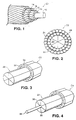
- C 1 illustrates an electrical transmission cable having a reinforced plastic composite load bearing core 10 and a plurality of outer layers of aluminum wire 12 and 14 extending thereabout.
- the load bearing core 10 is a solid reinforced plastic composite member. Also, in the embodiment as illustrated in Figure 1 and the subsequently illustrated and described embodiments, there are three outer aluminum layers 12, 18 and 14 (see Figure 1), although it should be understood that any number of outer layers could be employed depending upon the desired thickness of the outer current conducting sheath to be formed over the core. It can be observed that in this construction, the cable C 1 is similar in appearance to a conventional steel core cable. Consequently, it can be laid in the same fashion or suspended in the same fashion and using the same equipment as that employed for a steel core cable.
- the strands are formed of any suitable reinforcing fiber, such as glass, boron, carbon or the like.
- the resin matrix which is used to bind the strands may be formed of any suitable thermoplastic resin or thermosetting resin.
- thermosetting resins which may be used include, for example, various phenolics and epoxies and many polyesters which are conventionally known for that purpose.
- the thermoplastic resins are preferred and include, for example, polypropylene, polycarbonates, etc.
- the resin strands can be commingled with the fiber strands and they can be applied as a bundle. Otherwise, the resin strands can be applied individually with the fiber strands. Upon heating, the resin will then soften and liquefy and flow around the individual fiber containing strands. When the resin is allowed to harden, an inner core will therefore be formed.
- the composite core can be formed in any of a variety of ways.
- the composite core could be extruded, as such.
- the reinforced composite when formed as a rod in the embodiment as shown would preferably be pultruded.
- U.S. patents as, for example, U.S. Patent No. 3,650,864 to William Brandt Goldsworthy, U.S. Patent No. 3,576,705 to William Brandt Goldsworthy, U.S. Patent No. 3,769,127 to William Brandt Goldsworthy, and U.S. Patent No. 3,579,402 to William Brandt Goldsworthy, et al.
- the embodiment of Figure 1 is primarily effective for only short length cables. This is due to the fact that the reinforced plastic core 10 is not capable of significant bending movement. It may be appreciated that the entire cable must be capable of being wound about a drum and transported for a substantial distance where it would then be unwound from the drum and either suspended or laid at a site of use.
- the central core 10 is preferably formed of a plurality of individually shaped core sections 20, as best shown in the cable C 2 of Figure 2. In this particular case, the individual sections 20, when assembled together, create a cylindrically shaped cable 22.
- the cable C 2 is also wrapped with layers of electrically conductive material as, for example, individual strands of aluminum wire 24 and 26 which form the two outer electrically conductive layers. Again, any desired number of layers could be used. Furthermore, in the embodiment of Figure 2, the individual strands 24 and 26 are helically wound about the central load bearing core 22.
- Figure 3 illustrates an embodiment of a cable C 3 forming part of the present invention also having a segmented central core 22 and a pair of electrically conductive outer layers 30 and 32 wrapped about the central core.
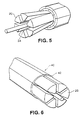
- Figure 4 illustrates an embodiment of a cable C 4 similar to the cable C 3 , except that in this particular case, the individual pie-shaped sections 20 of the core 22 are formed with an arcuately shaped recess 34 formed at their inner most ends.
- the inner most ends 34 as shown in Figures 4 and 5, form a cylindrically shaped central, axially extending bore 36 which are sized to receive a fiber optic cable 38.
- This embodiment of a cable C 4 is highly effective in that it not only provides for substantial current carrying capacity, but it also allows for the carrying of a fiber optic cable in such manner that the cable is not subjected to environmental degradation or the constant repair required for such cable.
- each of the individual sections 20 may be pre-formed in an extrusion operation, or otherwise a pultrusion operation, as previously described.
- These individual sections when hardened, are then threaded through a die plate or carding plate 40 having individual tubes 42 with essentially the same shape as the individual core sections 20, but sized to receive these core sections 20.
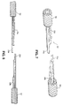
- Figures 7 and 8 illustrate a preferred embodiment for splicing the ends of the electrical transmission cable in accordance with the present invention.
- the individual cable sections 20 are each spliced with staggered ends, as best shown in Figure 7.
- one of the individual sections 20 a on one fiber optic cable 50 has a length which is longer than any other section of that cable 50.
- That particular core section 20 a will match and mate with the shortest cable section 20 b on an opposite cable 52 to be spliced.
- a shorter cable section 20 c on the cable 50 will match and mate with a cable section 20 d in the cable 52.
- each staggered length will mate with a corresponding staggered length of the opposite cable.
- the individual cable sections will then fit together much in the manner as pieces of a puzzle fit together.
- the individual staggered sections After the individual staggered sections have been brought together, they can be heated slightly to cause the thermoplastic resin or other resin to liquefy and flow between the staggered ends to thereby bind the staggered ends together.
- outer aluminum layers can then be coupled to one another in the same manner as they are presently coupled with steel core cables.
- outer electrically conductive layers of one cable 50 are connected to the outer electrically conductive layers of the cable 52 by use of electrically conductive sleeves which are secured thereto and extend over the joined ends, as best seen in Figure 9.
- the cable is brought to a ground level for connecting the ends of fiber optic cable sections.
- the technique for this arrangement is shown in the composite of Figures 9a through 9c.
- the two cable sections 50 and 52 when the splicing is completed are covered with an outer sheath 60, as shown in Figure 9a.
- Figure 9b which is a cross-section of Figure 9a, it can be seen that after the ends of the two cable sections 50 and 52 are spliced, the outer aluminum conductors 64 and 66 respectively on these cable sections are then brought together when the aluminum sleeve 60 is disposed thereover.
- the fiber optic cables Prior to actually installing the sheath, the fiber optic cables are brought to a ground level for purposes of splicing same. It can be seen by reference to Figure 9c that the cable sections are actually extended down toward a ground level for splicing at a splicing station and thereafter raised and located in the region of the sleeve 60 much in the manner as shown in Figure 9c.
- the electrical transmission cables of the invention also are adapted to carry more electrical current then a comparably sized steel core conductor. This is due to the fact that more of the highly conductive metal, such as aluminum, is capable of being carried with a reinforced plastic core then would be carried with a similarly sized steel cable with no weight increase and some weight decrease. As a result, support towers do not need to be rebuilt to accommodate heavier equivalent capacity conductors.
- the cables of the present invention will actually carry five percent more electrical current compared to a steel reinforced aluminum conductor. In addition, there is a reduced mechanical elongation or line sag at high operating temperatures. Further, it has actually been established that the cables of the invention are two hundred fifty percent stronger then the steel reinforced aluminum conductor of essentially the same size and, moreover, is seventy-five percent lighter than steel reinforced aluminum conductors.
Abstract
Description
- This invention relates in general to certain new and useful improvements in electrical transmission cables and, more particularly, to electrical transmission cables which have a composite reinforced component to provide load carrying capabilities.
- Electrical conductor technology has, in the relatively recent past, moved to the exploratory use of composite cores, such as carbon, ceramics and fiberglass. These materials offer unprecedented technical performance advantages over the earlier electrically conductive materials. It is desirable to provide a composite reinforced aluminum conductor for replacement of the heavy steel strength member of the aluminum core steel reiforced (ACSR) with a high strength and lower weight glass-fiber composite material. The current carrying component is still pure aluminum. The main difference between the ACSR and the composite reinforced aluminum conductor ("CRAC") is that the CRAC will have a higher percentage by volume of a conductive component. This improvement is actually made possible by the much greater tensile strength of a composite, such as glass resin, relative to the steel and this frees up space in the conductor's volume for more aluminum. This further significantly increases conductor current carrying capacity along with significantly lower weight.
- It can be seen from the above that some of the specific advantages of the CRAC is that:
- 1. The cost of the composite reinforced conductor is equal to or less than the cost of the traditional steel cable conductor of the same diameter.
- 2. The composite materials used as the center core have a coefficient of thermal expansion which is fifty percent less than the steel core reinforcement.
- 3. The tensile strength (breaking strength) is about one hundred fifty percent higher than carbon steel core wire (with HC steel being approximately 210ksi).
- 4. Conductivity of composite reinforced conductors is at least forty percent higher and having a target value of as much as two hundred percent higher than ACSR conductors of the same outer diameter.
- 5. The CRAC conductors are also capable of utilizing T&D accessories and other accessories which are installed in a similar manner in traditional cable.
- 6. The CRAC cables have the capability of being used with field installation equipment and procedures which exist with minimum modifications.
- 7. The composite materials are compatible with conventional wire and cable process technology.
- 8. The CRAC cables eliminate eddy-current heating.
- 9. A solid aluminum core has 1/100 degree of radial temperature differences as compared to stranded wire.
- 10. There is no loss of strength in a CRAC and consequent increase in sag due to annealing of the tension member.
- 11. The CRAC has simplified manufacturing requirements because there is no need for multiple layers of stranded aluminum in order to cancel out self-inductance.
- 12. There is an elimination of non-uniform current flow due to self-inductance when using the CRAC.
-
- The present invention relates in general to electrical current carrying conductors which utilize an inner load bearing core formed of a reinforced plastic composite material in place of the conventional steel core.
- The current carrying cable of the present invention in outer appearance is very similar to the conventional electrical current carrying cable having the inner steel core. In addition, and in one of the important aspects of the invention, the cable of the present invention can be used in precisely those locations in which conventional cables are presently used and they can be mounted in precisely the same manner. Thus, substitution of a cable of the type provided in accordance with the present invention can be accomplished easily and at low cost and, more importantly, with existing cable laying equipment.
- The current carrying conductor of the present invention includes the reinforced plastic composite core, as aforesaid. Preferably, this core is formed of individual segments which are fitted together to operate as a single composite fiber reinforced core. The individual segments are somewhat trapezoidal shaped with the outer surfaces thereof being arcuate. In this way, the trapezoidal shaped pieces as, for example, six individual pieces or segments of the core, are arranged in a cylindrical format so that the core actually is cylindrical when assembled.
- The inner core is formed of a plurality of fibers or strands of reinforcing material, such as fiberglass, boron, carbon or the like, and which are held together by a binding agent, such as a thermoplastic or thermosetting resin. Thermoplastic material is preferred due to the fact that it can be easily heated and bonded on a job site and also the heating and bonding occurs much more quickly with a thermoplastic material than with a thermosetting material.
- It has also been found that it is possible to literally use as smelted aluminum for higher current carrying conductivity capabilities.
- The present invention also provides a proposed method and system for splicing the ends of the individual cables. As indicated previously, the cables can only be carried to a job site in finite lengths. Consequently, the splicing of cable lengths is necessary for long distance transmission.
- Having thus described the invention in general terms, reference will now be made to the accompanying drawings in which:
- Figure 1 is a fragmentary perspective view of a composite reinforced current carrying conductor constructed in accordance with and embodying the present invention;
- Figure 2 is a fragmentary perspective view, similar to Figure 1, and showing a slightly modified form of composite reinforced current carrying conductor in accordance with the present invention;
- Figure 3 is a fragmentary perspective view showing still a further modified form of composite reinforced current carrying conductor in accordance with the present invention;
- Figure 4 is a fragmentary perspective view of yet another modified form of composite reinforced current carrying conductor in accordance with the present invention and containing the fiber optic cable;
- Figure 5 is a fragmentary perspective view, similar to Figure 4, and showing portions of the core spread apart to accept a fiber optic cable;
- Figure 6 is a fragmentary perspective view showing one form of apparatus for producing a composite reinforced current carrying conductor in accordance with the present invention;
- Figure 7 is an exploded perspective view showing one method of splicing ends of the current carrying conductor of the present invention;
- Figure 8 is a side elevational view showing the technique in the splicing of the cables of Figure 7; and
- Figure 9 is a composite of Figure 9a, 9b and 9c showing a finished splice and method providing a fiber optic cable to be spliced at a ground level.
-
- Referring now in more detail and by reference characters to the drawings, which illustrate preferred embodiments of the present invention, C1 illustrates an electrical transmission cable having a reinforced plastic composite
load bearing core 10 and a plurality of outer layers ofaluminum wire - By further reference to Figure 1, it can be seen that the
load bearing core 10 is a solid reinforced plastic composite member. Also, in the embodiment as illustrated in Figure 1 and the subsequently illustrated and described embodiments, there are threeouter aluminum layers - In a preferred embodiment, the strands are formed of any suitable reinforcing fiber, such as glass, boron, carbon or the like. Moreover, the resin matrix which is used to bind the strands may be formed of any suitable thermoplastic resin or thermosetting resin. Some of the thermosetting resins which may be used include, for example, various phenolics and epoxies and many polyesters which are conventionally known for that purpose. However, the thermoplastic resins are preferred and include, for example, polypropylene, polycarbonates, etc.
- It is preferred to use individual ropes or strands of thermoplastic resin along with the individual strands of the fiber reinforcing strands. Thus, the resin strands can be commingled with the fiber strands and they can be applied as a bundle. Otherwise, the resin strands can be applied individually with the fiber strands. Upon heating, the resin will then soften and liquefy and flow around the individual fiber containing strands. When the resin is allowed to harden, an inner core will therefore be formed.
- It should also be understood in connection with the present invention that aluminum is only one form of current carrying conductor which could be employed as the outer skin. Thus, copper or other high current conductivity materials could be used for this purpose.
- The composite core can be formed in any of a variety of ways. For example, the composite core could be extruded, as such. However, preferably, the reinforced composite when formed as a rod in the embodiment as shown, would preferably be pultruded. Several processes for this pultrusion operation are described in numerous U.S. patents as, for example, U.S. Patent No. 3,650,864 to William Brandt Goldsworthy, U.S. Patent No. 3,576,705 to William Brandt Goldsworthy, U.S. Patent No. 3,769,127 to William Brandt Goldsworthy, and U.S. Patent No. 3,579,402 to William Brandt Goldsworthy, et al.
- The embodiment of Figure 1 is primarily effective for only short length cables. This is due to the fact that the reinforced
plastic core 10 is not capable of significant bending movement. It may be appreciated that the entire cable must be capable of being wound about a drum and transported for a substantial distance where it would then be unwound from the drum and either suspended or laid at a site of use. For this purpose, thecentral core 10 is preferably formed of a plurality of individually shapedcore sections 20, as best shown in the cable C2 of Figure 2. In this particular case, theindividual sections 20, when assembled together, create a cylindrically shapedcable 22. - In the embodiment of the invention as shown in Figure 2, six individual pie-shaped sections are provided. However, any number of sections could be provided. In connection with the present invention, it has been found that the five individual sections are preferred inasmuch as this is the number of sections which allow for a bending of the cable and a winding of the cable about a spool.
- The cable C2, as shown in the embodiment of Figure 2, is also wrapped with layers of electrically conductive material as, for example, individual strands of
aluminum wire individual strands load bearing core 22. - In connection with the following described embodiments, like reference numerals will represent like components. Figure 3 illustrates an embodiment of a cable C3 forming part of the present invention also having a segmented
central core 22 and a pair of electrically conductiveouter layers - Figure 4 illustrates an embodiment of a cable C4 similar to the cable C3, except that in this particular case, the individual pie-shaped
sections 20 of the core 22 are formed with an arcuately shapedrecess 34 formed at their inner most ends. In this particular embodiment, the inner most ends 34, as shown in Figures 4 and 5, form a cylindrically shaped central, axially extendingbore 36 which are sized to receive afiber optic cable 38. - This embodiment of a cable C4 is highly effective in that it not only provides for substantial current carrying capacity, but it also allows for the carrying of a fiber optic cable in such manner that the cable is not subjected to environmental degradation or the constant repair required for such cable.
- With presently employed fiber optic cable for transmitting fiber optic messages over long distance, a complex scheme is required for splicing ends of the fiber optic cable and, for that matter, even repairing the cable. Typically, the cable must be lowered to a repair station or otherwise a splicing station located approximately at ground level. Moreover, with a conventional steel core electrical transmission cable, there is no effective way to form a central opening extending axially through the core and no effective way to even thread a fiber optic cable through an opening in the core. As a result, and as indicated previously, fiber optic cable is wrapped about the outer surface of the guard wire. The present invention overcomes this problem completely, in that the fiber optic cable can be literally enclosed in the electrical transmission cable as the latter is being formed.
- By reference to Figure 6 of the drawings, it can be observed that each of the
individual sections 20 may be pre-formed in an extrusion operation, or otherwise a pultrusion operation, as previously described. These individual sections, when hardened, are then threaded through a die plate or cardingplate 40 havingindividual tubes 42 with essentially the same shape as theindividual core sections 20, but sized to receive thesecore sections 20. - Figures 7 and 8 illustrate a preferred embodiment for splicing the ends of the electrical transmission cable in accordance with the present invention. In this particular case, and in order to splice the ends together, the
individual cable sections 20 are each spliced with staggered ends, as best shown in Figure 7. Thus, one of theindividual sections 20a on onefiber optic cable 50 has a length which is longer than any other section of thatcable 50. Thatparticular core section 20a will match and mate with theshortest cable section 20b on anopposite cable 52 to be spliced. In this manner, ashorter cable section 20c on thecable 50 will match and mate with acable section 20d in thecable 52. In this way, each staggered length will mate with a corresponding staggered length of the opposite cable. Moreover, the individual cable sections will then fit together much in the manner as pieces of a puzzle fit together. - After the individual staggered sections have been brought together, they can be heated slightly to cause the thermoplastic resin or other resin to liquefy and flow between the staggered ends to thereby bind the staggered ends together.
- Thereafter, the outer aluminum layers can then be coupled to one another in the same manner as they are presently coupled with steel core cables. Typically, the outer electrically conductive layers of one
cable 50 are connected to the outer electrically conductive layers of thecable 52 by use of electrically conductive sleeves which are secured thereto and extend over the joined ends, as best seen in Figure 9. - In accordance with standard cable splicing techniques, and particularly for fiber optic cable, the cable is brought to a ground level for connecting the ends of fiber optic cable sections. The technique for this arrangement is shown in the composite of Figures 9a through 9c. The two
cable sections outer sheath 60, as shown in Figure 9a. By reference to Figure 9b, which is a cross-section of Figure 9a, it can be seen that after the ends of the twocable sections outer aluminum conductors aluminum sleeve 60 is disposed thereover. Prior to actually installing the sheath, the fiber optic cables are brought to a ground level for purposes of splicing same. It can be seen by reference to Figure 9c that the cable sections are actually extended down toward a ground level for splicing at a splicing station and thereafter raised and located in the region of thesleeve 60 much in the manner as shown in Figure 9c. - The electrical transmission cables of the invention also are adapted to carry more electrical current then a comparably sized steel core conductor. This is due to the fact that more of the highly conductive metal, such as aluminum, is capable of being carried with a reinforced plastic core then would be carried with a similarly sized steel cable with no weight increase and some weight decrease. As a result, support towers do not need to be rebuilt to accommodate heavier equivalent capacity conductors.
- It has been found that the cables of the present invention will actually carry five percent more electrical current compared to a steel reinforced aluminum conductor. In addition, there is a reduced mechanical elongation or line sag at high operating temperatures. Further, it has actually been established that the cables of the invention are two hundred fifty percent stronger then the steel reinforced aluminum conductor of essentially the same size and, moreover, is seventy-five percent lighter than steel reinforced aluminum conductors.
Claims (11)
- An improved electrical current carrying conductor for long distance transmission of electrical current and having a central load carrying conductor and an outer sheath therearound, the improvement in said current carrying conductor further characterized in that:a) the load carrying core being formed of a fiber containing reinforced composite material; andb) the outer highly conductive electrical current carrying sheath completely surrounding said load carrying core.
- The improved electrical current carrying conductor of Claim 1 further characterized in that said reinforced composite material is comprised of a plurality of aligned reinforcing fibers embedded in a thermoplastic composite matrix.
- The improved electrical current carrying conductor of Claim 1 further characterized in that said central load carrying core is comprised of a plurality of individual sections which are capable of being separated from one another for purposes of splicing.
- The improved electrical current carrying conductor of Claim 3 further characterized in that said individual sections are concentrically arranged to form a cylindrically shaped conductor and that said individual sections are somewhat trapezoidal shaped and form a central bore sized to receive a fiber optic cable.
- An improved method for producing a long distance transmission current carrying conductor of Claim 1 wherein the improved method is characterized in the steps of:a) bringing a plurality of individual reinforced plastic composite sections together to form a generally cylindrically shaped conductor core; andb) locating on an outer cylindrically shaped surface of said core an outer highly conductive electrical current carrying conductor.
- The improved method for producing a long distance transmission current carrying conductor of Claim 5 further characterized in that said step of locating the current carrying conductor comprises winding strands of a highly conductive current carrying conductor about said central core.
- The improved method for producing a long distance transmission current carrying conductor of Claim 5 further characterized in that said method comprises the bringing of the composite sections together about a fiber optic cable so that the current carrying conductor also includes a fiber optic cable therein.
- A method for splicing ends of improved first and second current carrying cables of Claim 5 comprised of a fiber containing reinforced plastic composite core and an outer highly conductive current carrying sheath, said method comprising:a) cutting the ends of the individual sections of a first cable to be spliced at staggered lengths relative to one another so that each section of the central core of that cable has a length different from the length of any other section of that first cable;b) cutting the ends of the individual sections of a second cable to be spliced at staggered lengths relative to one another so that each section of the central core of that second cable has a length different from the length of any other section of that second cable;c) matching the ends of the first cable sections with corresponding ends of the second cable so that the ends of the first cable sections will abut against corresponding ends of the second cable sections when all of the individual sections are abutted;d) heating spliced ends of the individual cable sections as abutted to cause a resin impregnated in the cables to partially liquefy and effectively flow around corresponding ends; ande) allowing the resin to cool thereby permanently bonding the core sections of the first cable to the core sections of the second cable.
- The method of splicing cables of Claim 8 further characterized in that said method comprises matching the shortest length of a cable section of the first cable with the longest length cable section of the second cable and correspondingly matching the longest length section of the first cable with the correspondingly shortest length section of the second cable.
- The method of splicing cables of Claim 9 further characterized in that said method comprises securing the ends of an electrically conductive current carrying sheath on said first and second cables together in order to permit electrical conductivity through the sheaths of said cables.
- The method of splicing cables of Claim 8 further characterized in that said method also comprises splicing the ends of fiber optic cables carried in the core of each of the individual first and second cables.
Priority Applications (1)
| Application Number | Priority Date | Filing Date | Title |
|---|---|---|---|
| EP08004899A EP1930914A3 (en) | 2000-02-08 | 2001-02-06 | Composite reinforced electrical transmission conductor |
Applications Claiming Priority (2)
| Application Number | Priority Date | Filing Date | Title |
|---|---|---|---|
| US50028500A | 2000-02-08 | 2000-02-08 | |
| US500285 | 2000-02-08 |
Related Child Applications (1)
| Application Number | Title | Priority Date | Filing Date |
|---|---|---|---|
| EP08004899A Division EP1930914A3 (en) | 2000-02-08 | 2001-02-06 | Composite reinforced electrical transmission conductor |
Publications (3)
| Publication Number | Publication Date |
|---|---|
| EP1124235A2 true EP1124235A2 (en) | 2001-08-16 |
| EP1124235A3 EP1124235A3 (en) | 2002-11-06 |
| EP1124235B1 EP1124235B1 (en) | 2008-10-15 |
Family
ID=23988756
Family Applications (2)
| Application Number | Title | Priority Date | Filing Date |
|---|---|---|---|
| EP01102558A Expired - Lifetime EP1124235B1 (en) | 2000-02-08 | 2001-02-06 | Composite reinforced electrical transmission conductor |
| EP08004899A Withdrawn EP1930914A3 (en) | 2000-02-08 | 2001-02-06 | Composite reinforced electrical transmission conductor |
Family Applications After (1)
| Application Number | Title | Priority Date | Filing Date |
|---|---|---|---|
| EP08004899A Withdrawn EP1930914A3 (en) | 2000-02-08 | 2001-02-06 | Composite reinforced electrical transmission conductor |
Country Status (9)
| Country | Link |
|---|---|
| US (4) | US7015395B2 (en) |
| EP (2) | EP1124235B1 (en) |
| JP (1) | JP2001307552A (en) |
| AT (1) | ATE411607T1 (en) |
| DE (1) | DE60136116D1 (en) |
| DK (1) | DK1124235T3 (en) |
| ES (1) | ES2315249T3 (en) |
| GE (1) | GEP20105120B (en) |
| TW (1) | TW480497B (en) |
Cited By (12)
| Publication number | Priority date | Publication date | Assignee | Title |
|---|---|---|---|---|
| WO2003091008A1 (en) | 2002-04-23 | 2003-11-06 | Composite Technology Corporation | Aluminum conductor composite core reinforced cable and method of manufacture |
| WO2005089410A2 (en) * | 2004-03-17 | 2005-09-29 | Gift Technologies, Lp | Electrical conductor cable and method for forming the same |
| US7019217B2 (en) | 2002-04-23 | 2006-03-28 | Ctc Cable Corporation | Collet-type splice and dead end use with an aluminum conductor composite core reinforced cable |
| EP1678063A2 (en) * | 2003-10-22 | 2006-07-12 | CTC Cable Corporation | Aluminum conductor composite core reinforced cable and method of manufacture |
| US7179522B2 (en) | 2002-04-23 | 2007-02-20 | Ctc Cable Corporation | Aluminum conductor composite core reinforced cable and method of manufacture |
| US7298957B2 (en) | 2005-07-11 | 2007-11-20 | Gift Technologies, Lp | Method for controlling sagging of a power transmission cable |
| EP1928001A1 (en) * | 2006-12-01 | 2008-06-04 | Nexans | Electrical transport conductor for overhead line |
| US7438971B2 (en) | 2003-10-22 | 2008-10-21 | Ctc Cable Corporation | Aluminum conductor composite core reinforced cable and method of manufacture |
| US7563983B2 (en) | 2002-04-23 | 2009-07-21 | Ctc Cable Corporation | Collet-type splice and dead end for use with an aluminum conductor composite core reinforced cable |
| US20100181012A1 (en) * | 2002-04-23 | 2010-07-22 | Ctc Cable Corporation | Method for the manufacture of a composite core for an electrical cable |
| CN101807446A (en) * | 2010-04-01 | 2010-08-18 | 张国志 | Cable composite core and manufacturing method thereof |
| EP1992053A4 (en) * | 2006-03-07 | 2016-10-19 | 3M Innovative Properties Co | Installation of spliced electrical transmission cables |
Families Citing this family (86)
| Publication number | Priority date | Publication date | Assignee | Title |
|---|---|---|---|---|
| EP1124235B1 (en) * | 2000-02-08 | 2008-10-15 | W. Brandt Goldsworthy & Associates, Inc. | Composite reinforced electrical transmission conductor |
| FI119583B (en) | 2003-02-26 | 2008-12-31 | Imbera Electronics Oy | Procedure for manufacturing an electronics module |
| US20050186410A1 (en) * | 2003-04-23 | 2005-08-25 | David Bryant | Aluminum conductor composite core reinforced cable and method of manufacture |
| US20050181228A1 (en) * | 2004-02-13 | 2005-08-18 | 3M Innovative Properties Company | Metal-cladded metal matrix composite wire |
| US7131308B2 (en) * | 2004-02-13 | 2006-11-07 | 3M Innovative Properties Company | Method for making metal cladded metal matrix composite wire |
| US7093416B2 (en) * | 2004-06-17 | 2006-08-22 | 3M Innovative Properties Company | Cable and method of making the same |
| US20050279527A1 (en) * | 2004-06-17 | 2005-12-22 | Johnson Douglas E | Cable and method of making the same |
| US20050279526A1 (en) * | 2004-06-17 | 2005-12-22 | Johnson Douglas E | Cable and method of making the same |
| JP2006339144A (en) * | 2005-05-31 | 2006-12-14 | Ngk Insulators Ltd | Plasma treatment device |
| US7262595B2 (en) * | 2005-07-27 | 2007-08-28 | Simmonds Precision Products, Inc. | Segmented core for an inductive proximity sensor |
| FR2896911B1 (en) * | 2006-02-01 | 2008-03-21 | Nexans Sa | ELECTRICAL TRANSPORT CONDUCTOR FOR AERIAL LINE |
| US20110135423A1 (en) * | 2006-05-18 | 2011-06-09 | Duratel, Llc | Apparatus for transporting and raising pultruded/extruded utility support structures |
| US8322105B2 (en) * | 2006-05-18 | 2012-12-04 | Duratel, Llc | Pultruded utility support structures |
| US8359814B2 (en) * | 2006-05-18 | 2013-01-29 | Duratel, Inc. | Pultruded/extruded utility lighting, mounting and climbing structures |
| US8024908B2 (en) | 2006-05-18 | 2011-09-27 | Williams Donald S | Pultruded utility structures |
| US7390963B2 (en) * | 2006-06-08 | 2008-06-24 | 3M Innovative Properties Company | Metal/ceramic composite conductor and cable including same |
| US7403686B1 (en) * | 2006-11-30 | 2008-07-22 | The United States Of America As Represented By The Secretary Of The Navy | Fiber optic cable splicing technique |
| US8246393B2 (en) * | 2007-03-12 | 2012-08-21 | Hubbell Incorporated | Implosion connector and method for use with transmission line conductors comprising composite cores |
| US8471416B2 (en) * | 2008-05-29 | 2013-06-25 | Lionel O. Barthold | In situ reconstruction of high voltage electric power lines |
| JP4883051B2 (en) * | 2008-06-19 | 2012-02-22 | トヨタ自動車株式会社 | Wire Harness |
| BRPI0910163A2 (en) * | 2008-06-27 | 2016-01-19 | Union Carbide Chem Plastic | composite core fabrication process for accc cables and process for manufacturing resin impregnated cables or fibers |
| CA2729741A1 (en) * | 2008-07-01 | 2010-01-07 | Dow Global Technologies Inc. | Fiber-polymer composite |
| CA2767809A1 (en) | 2009-07-16 | 2011-01-20 | 3M Innovative Properties Company | Submersible composite cable and methods |
| KR101844815B1 (en) * | 2009-11-11 | 2018-04-03 | 보레알리스 아게 | A polymer composition comprising a polyolefin produced in a high pressure process, a high pressure process and an article |
| KR101813295B1 (en) | 2009-11-11 | 2017-12-28 | 보레알리스 아게 | A polymer composition and a power cable comprising the polymer composition |
| KR101962839B1 (en) | 2009-11-11 | 2019-03-27 | 보레알리스 아게 | Crosslinkable polymer composition and cable with advantageous electrical properties |
| ES2758129T3 (en) | 2009-11-11 | 2020-05-04 | Borealis Ag | A cable and its production procedure |
| WO2011090133A1 (en) * | 2010-01-20 | 2011-07-28 | 古河電気工業株式会社 | Composite electric cable and process for producing same |
| EP2532012A1 (en) * | 2010-02-01 | 2012-12-12 | 3M Innovative Properties Company | Stranded thermoplastic polymer composite cable, method of making and using same |
| US10422578B2 (en) * | 2010-04-08 | 2019-09-24 | Ncc Nano, Pllc | Apparatus for curing thin films on a moving substrate |
| WO2011127248A1 (en) * | 2010-04-08 | 2011-10-13 | Ncc Nano, Llc | Apparatus for curing thin films on a moving substrate |
| US8648254B2 (en) * | 2010-04-27 | 2014-02-11 | Michels Corporation | Device and method for stringing overhead cable |
| US20110302611A1 (en) * | 2010-06-07 | 2011-12-08 | Mark Kenneth Eyer | Scripted Interactivity for Non-Real-Time Services |
| US8568015B2 (en) | 2010-09-23 | 2013-10-29 | Willis Electric Co., Ltd. | Decorative light string for artificial lighted tree |
| EP3591670A1 (en) | 2010-11-03 | 2020-01-08 | Borealis AG | A polymer composition and a power cable comprising the polymer composition |
| JP5698971B2 (en) * | 2010-12-28 | 2015-04-08 | 宇部エクシモ株式会社 | Manufacturing method of spacer for optical cable |
| BR112013019053A2 (en) | 2011-01-24 | 2016-10-04 | Gift Technologies Llc | composite core conductors with method to produce the same |
| AU2012242930B2 (en) | 2011-04-12 | 2016-03-31 | Southwire Company | Electrical transmission cables with composite cores |
| JP2014516822A (en) | 2011-04-12 | 2014-07-17 | ティコナ・エルエルシー | Thermoplastic rod reinforced with continuous fiber and extrusion process for its production |
| KR20140027252A (en) | 2011-04-12 | 2014-03-06 | 티코나 엘엘씨 | Composite core for electrical transmission cables |
| RU2013150190A (en) | 2011-04-12 | 2015-05-20 | ТИКОНА ЭлЭлСи | HOSE CABLE FOR USE IN UNDERWATER APPLICATIONS |
| JP6276686B2 (en) | 2011-04-12 | 2018-02-07 | ティコナ・エルエルシー | Die and method for impregnating fiber roving |
| WO2012141689A1 (en) | 2011-04-12 | 2012-10-18 | Ticona Llc | Impregnation section of die and method for impregnating fiber rovings |
| US9623437B2 (en) | 2011-04-29 | 2017-04-18 | Ticona Llc | Die with flow diffusing gate passage and method for impregnating same fiber rovings |
| CA2775445C (en) | 2011-04-29 | 2019-04-09 | Ticona Llc | Die and method for impregnating fiber rovings |
| CA2775442C (en) | 2011-04-29 | 2019-01-08 | Ticona Llc | Impregnation section with upstream surface and method for impregnating fiber rovings |
| WO2013016121A1 (en) | 2011-07-22 | 2013-01-31 | Ticona Llc | Extruder and method for producing high fiber density resin structures |
| US9157587B2 (en) | 2011-11-14 | 2015-10-13 | Willis Electric Co., Ltd. | Conformal power adapter for lighted artificial tree |
| US8569960B2 (en) | 2011-11-14 | 2013-10-29 | Willis Electric Co., Ltd | Conformal power adapter for lighted artificial tree |
| US9321073B2 (en) | 2011-12-09 | 2016-04-26 | Ticona Llc | Impregnation section of die for impregnating fiber rovings |
| US9283708B2 (en) | 2011-12-09 | 2016-03-15 | Ticona Llc | Impregnation section for impregnating fiber rovings |
| US9409355B2 (en) | 2011-12-09 | 2016-08-09 | Ticona Llc | System and method for impregnating fiber rovings |
| WO2013086258A1 (en) | 2011-12-09 | 2013-06-13 | Ticona Llc | Asymmetric fiber reinforced polymer tape |
| US9289936B2 (en) | 2011-12-09 | 2016-03-22 | Ticona Llc | Impregnation section of die for impregnating fiber rovings |
| US8474221B1 (en) | 2012-01-20 | 2013-07-02 | Trident Industries, LLC | Telescoping fiberglass utility pole |
| US9044056B2 (en) | 2012-05-08 | 2015-06-02 | Willis Electric Co., Ltd. | Modular tree with electrical connector |
| US9410644B2 (en) | 2012-06-15 | 2016-08-09 | Ticona Llc | Subsea pipe section with reinforcement layer |
| US9859038B2 (en) | 2012-08-10 | 2018-01-02 | General Cable Technologies Corporation | Surface modified overhead conductor |
| CN102903424B (en) * | 2012-09-28 | 2017-10-27 | 中国电力科学研究院 | One kind is sparsely stranded type expanded diameter conductor |
| US10957468B2 (en) | 2013-02-26 | 2021-03-23 | General Cable Technologies Corporation | Coated overhead conductors and methods |
| US9140438B2 (en) | 2013-09-13 | 2015-09-22 | Willis Electric Co., Ltd. | Decorative lighting with reinforced wiring |
| US10267464B2 (en) | 2015-10-26 | 2019-04-23 | Willis Electric Co., Ltd. | Tangle-resistant decorative lighting assembly |
| US9157588B2 (en) * | 2013-09-13 | 2015-10-13 | Willis Electric Co., Ltd | Decorative lighting with reinforced wiring |
| US11306881B2 (en) | 2013-09-13 | 2022-04-19 | Willis Electric Co., Ltd. | Tangle-resistant decorative lighting assembly |
| US20150104641A1 (en) | 2013-10-10 | 2015-04-16 | Emisshield, Inc. | Coated overhead conductor |
| AR099038A1 (en) | 2014-01-08 | 2016-06-22 | General Cable Tech Corp | COVERED AIR CONDUCTOR |
| CN106415738A (en) * | 2014-04-09 | 2017-02-15 | 意大利德安产品有限公司 | Conductor for bare overhead electric lines, especially for middle-high thermal limit, and low expansion at high electronic loads |
| BR112017002151A2 (en) | 2014-08-05 | 2018-07-03 | Gen Cable Technologies Corp | fluorine coatings copolymers for air conductors |
| EP3197612A4 (en) | 2014-09-23 | 2018-05-23 | General Cable Technologies Corporation | Electrodeposition mediums for formation of protective coatings electrochemically deposited on metal substrates |
| US9633766B2 (en) * | 2014-09-26 | 2017-04-25 | Jianping Huang | Energy efficient conductors with reduced thermal knee points and the method of manufacture thereof |
| ES2833401T3 (en) * | 2014-09-26 | 2021-06-15 | Jianping Huang | Energy efficient conductors with reduced thermal tipping points and their manufacturing method |
| EP3250785B1 (en) | 2015-01-26 | 2022-09-21 | Services Pétroliers Schlumberger | Electrically conductive fiber optic slickline for coiled tubing operations |
| BR112018001195B1 (en) | 2015-07-21 | 2022-08-09 | General Cable Technologies Corp | ELECTRICAL ACCESSORIES FOR POWER TRANSMISSION SYSTEMS AND METHODS FOR PREPARING SUCH ELECTRICAL ACCESSORIES |
| CN105680391B (en) * | 2015-09-06 | 2018-03-02 | 北京帕尔普线路器材有限公司 | A kind of composite core strengthens cable strain clamp |
| EP3362581B1 (en) | 2015-10-14 | 2022-09-14 | Nanoal LLC | Aluminum-iron-zirconium alloys |
| EP3374453B1 (en) | 2015-11-13 | 2020-01-08 | General Cable Technologies Corporation | Cables coated with fluorocopolymer coatings |
| EP3452560A4 (en) | 2016-05-04 | 2020-04-08 | General Cable Technologies Corporation | Compositions and coatings formed thereof with reduced ice adherence and accumulation |
| US9755734B1 (en) * | 2016-06-09 | 2017-09-05 | Google Inc. | Subsea optical communication network |
| US10049789B2 (en) * | 2016-06-09 | 2018-08-14 | Schlumberger Technology Corporation | Compression and stretch resistant components and cables for oilfield applications |
| HUE064526T2 (en) | 2016-10-20 | 2024-03-28 | Gen Cable Technologies Corp | Durable coating compositions and coatings formed thereof |
| HUE064330T2 (en) | 2016-10-28 | 2024-03-28 | Gen Cable Technologies Corp | Ambient cured coating compositions for cables and cable accessories |
| US11107604B2 (en) * | 2017-02-08 | 2021-08-31 | Prysmian S.P.A | Cable or flexible pipe with improved tensile elements |
| CN109448917A (en) * | 2018-11-02 | 2019-03-08 | 江苏中天科技股份有限公司 | A kind of energy-saving low arc drop extra-heavy steel reinforced soft aluminum strand and its production technology |
| CN110660518A (en) * | 2019-10-14 | 2020-01-07 | 江苏泰祥电线电缆有限公司 | High-strength tensile cable for ladle car |
| WO2023192807A1 (en) | 2022-03-28 | 2023-10-05 | Ts Conductor Corp. | Composite conductors including radiative and/or hard coatings and methods of manufacture thereof |
| CL2022001746A1 (en) * | 2022-06-24 | 2022-11-18 | Cable for laying overhead power lines with catenary for railways with pantograph. |
Citations (2)
| Publication number | Priority date | Publication date | Assignee | Title |
|---|---|---|---|---|
| US5198621A (en) * | 1991-12-31 | 1993-03-30 | The Furukawa Electric Co., Ltd. | Twisted cable |
| EP0814355A1 (en) * | 1996-06-21 | 1997-12-29 | Lucent Technologies Inc. | Lightweight optical groundwire |
Family Cites Families (38)
| Publication number | Priority date | Publication date | Assignee | Title |
|---|---|---|---|---|
| US32374A (en) * | 1861-05-21 | Portfolio foe filing music | ||
| FR959407A (en) * | 1947-01-11 | 1950-03-30 | ||
| US2901725A (en) * | 1954-12-13 | 1959-08-25 | Fargo Mfg Co Inc | Line splice clamp |
| US3324233A (en) * | 1965-04-08 | 1967-06-06 | Amphenol Corp | Cable complex employing strand twist reversal to absorb longitudinal expansion |
| US3384247A (en) * | 1965-10-22 | 1968-05-21 | Harold C. Teagle | Universal mount apparatus |
| US3576705A (en) | 1967-10-12 | 1971-04-27 | William B Goldsworthy | Uncured resin coated filament reinforced product |
| US3579402A (en) | 1968-04-23 | 1971-05-18 | Goldsworthy Eng Inc | Method and apparatus for producing filament reinforced tubular products on a continuous basis |
| US3769127A (en) | 1968-04-23 | 1973-10-30 | Goldsworthy Eng Inc | Method and apparatus for producing filament reinforced tubular products on a continuous basis |
| US3650864A (en) | 1969-07-23 | 1972-03-21 | Goldsworthy Eng Inc | Method for making filament reinforced a-stage profiles |
| US3717720A (en) * | 1971-03-22 | 1973-02-20 | Norfin | Electrical transmission cable system |
| US3996417A (en) * | 1974-09-12 | 1976-12-07 | Aluminum Company Of America | Cable core grip, electrical cable and connector assembly, and electrical connector kit |
| GB1478705A (en) * | 1974-09-13 | 1977-07-06 | Furukawa Electric Co Ltd | Connector for fibre reinforced plastics filaments or cord |
| CA1112310A (en) * | 1977-05-13 | 1981-11-10 | Peter Fearns | Overhead electric transmission systems |
| FR2422969A1 (en) * | 1978-03-31 | 1979-11-09 | Kokusai Denshin Denwa Co Ltd | FIBER OPTIC UNDERWATER CABLE |
| EP0054784B1 (en) * | 1980-12-19 | 1985-04-10 | Kupferdraht-Isolierwerk AG Wildegg | Overhead cable with tension members |
| US4441787A (en) * | 1981-04-29 | 1984-04-10 | Cooper Industries, Inc. | Fiber optic cable and method of manufacture |
| JPS6045212A (en) * | 1983-08-23 | 1985-03-11 | Sumitomo Electric Ind Ltd | Optical fiber cable |
| IT1174109B (en) * | 1984-05-29 | 1987-07-01 | Pirelli Cavi Spa | IMPROVEMENT OF SUBMARINE OPTICAL CABLES FOR TELECOMMUNICATIONS |
| GB8600294D0 (en) * | 1986-01-07 | 1986-02-12 | Bicc Plc | Optical cable |
| US5285613A (en) * | 1992-01-31 | 1994-02-15 | Goldsworthy W Brandt | Pultruded joint system and tower structure made therewith |
| US4770489A (en) * | 1986-08-27 | 1988-09-13 | Sumitomo Electric Research Triangle, Inc. | Ruggedized optical communication cable |
| DE3935017A1 (en) * | 1989-10-20 | 1991-04-25 | Kabelmetal Electro Gmbh | Jointing system for electric cable with high tensile core - has modified crimp connector with transverse holes for anchoring high tensile plastic core using conventional tools |
| JPH07113068B2 (en) * | 1989-12-11 | 1995-12-06 | 東レ株式会社 | Fiber-reinforced foam and method for producing the same |
| DE4000605A1 (en) * | 1990-01-11 | 1991-07-18 | Philips Patentverwaltung | ELECTRICAL WIRING CABLE WITH INTEGRATED OPTICAL NEWS LINE |
| DE9013175U1 (en) * | 1990-09-17 | 1991-02-21 | Felten & Guilleaume Energietechnik Ag, 5000 Koeln, De | |
| FR2675963B1 (en) * | 1991-04-29 | 1993-07-23 | Electricite De France | HELICOPTERED PLATFORM AND METHOD OF USING THE SAME TO REPLACE A PORTION OF AN AIR CABLE. |
| JPH05154919A (en) * | 1991-12-03 | 1993-06-22 | Fujikura Ltd | Connecting method of frp wiry body |
| DE4142047C2 (en) * | 1991-12-19 | 2001-03-01 | Siemens Ag | Method for covering at least one optical waveguide with a protective layer and for attaching reinforcing elements |
| US6343363B1 (en) * | 1994-09-22 | 2002-01-29 | National Semiconductor Corporation | Method of invoking a low power mode in a computer system using a halt instruction |
| JP2588486Y2 (en) | 1992-06-30 | 1999-01-13 | 古河電気工業株式会社 | Overhead wire |
| JPH08335357A (en) * | 1995-06-08 | 1996-12-17 | Fujitsu Ltd | Storage device |
| US6245425B1 (en) * | 1995-06-21 | 2001-06-12 | 3M Innovative Properties Company | Fiber reinforced aluminum matrix composite wire |
| US5808239A (en) * | 1996-02-29 | 1998-09-15 | Deepsea Power & Light | Video push-cable |
| US5714870A (en) * | 1996-12-18 | 1998-02-03 | Intel Corporation | Method for measuring suspend-time power consumption in a battery-powered electronic device |
| JPH10321048A (en) * | 1997-05-16 | 1998-12-04 | Furukawa Electric Co Ltd:The | Tension member and lightweight/low slackness overhead wire using the tension member |
| JP2001154844A (en) * | 1999-11-30 | 2001-06-08 | Nec Corp | Single chip microcomputer |
| EP1124235B1 (en) * | 2000-02-08 | 2008-10-15 | W. Brandt Goldsworthy & Associates, Inc. | Composite reinforced electrical transmission conductor |
| US6986070B2 (en) * | 2000-12-28 | 2006-01-10 | Denso Corporation | Microcomputer that cooperates with an external apparatus to be driven by a drive signal |
-
2001
- 2001-02-06 EP EP01102558A patent/EP1124235B1/en not_active Expired - Lifetime
- 2001-02-06 DE DE60136116T patent/DE60136116D1/en not_active Expired - Lifetime
- 2001-02-06 EP EP08004899A patent/EP1930914A3/en not_active Withdrawn
- 2001-02-06 AT AT01102558T patent/ATE411607T1/en active
- 2001-02-06 DK DK01102558T patent/DK1124235T3/en active
- 2001-02-06 ES ES01102558T patent/ES2315249T3/en not_active Expired - Lifetime
- 2001-02-08 JP JP2001032774A patent/JP2001307552A/en active Pending
- 2001-03-27 TW TW090102655A patent/TW480497B/en not_active IP Right Cessation
- 2001-12-28 US US10/037,814 patent/US7015395B2/en not_active Expired - Fee Related
-
2005
- 2005-07-27 US US11/191,863 patent/US20060016616A1/en not_active Abandoned
-
2008
- 2008-01-09 US US12/008,389 patent/US7752754B2/en not_active Expired - Fee Related
-
2010
- 2010-05-10 GE GEAP201011791A patent/GEP20105120B/en unknown
- 2010-05-26 US US12/788,182 patent/US8371028B2/en not_active Expired - Fee Related
Patent Citations (2)
| Publication number | Priority date | Publication date | Assignee | Title |
|---|---|---|---|---|
| US5198621A (en) * | 1991-12-31 | 1993-03-30 | The Furukawa Electric Co., Ltd. | Twisted cable |
| EP0814355A1 (en) * | 1996-06-21 | 1997-12-29 | Lucent Technologies Inc. | Lightweight optical groundwire |
Cited By (25)
| Publication number | Priority date | Publication date | Assignee | Title |
|---|---|---|---|---|
| WO2003091008A1 (en) | 2002-04-23 | 2003-11-06 | Composite Technology Corporation | Aluminum conductor composite core reinforced cable and method of manufacture |
| EP1506085B1 (en) | 2002-04-23 | 2016-12-07 | CTC Global Corporation | Aluminum conductor composite core reinforced cable and method of manufacture |
| US9093191B2 (en) | 2002-04-23 | 2015-07-28 | CTC Global Corp. | Fiber reinforced composite core for an aluminum conductor cable |
| US7019217B2 (en) | 2002-04-23 | 2006-03-28 | Ctc Cable Corporation | Collet-type splice and dead end use with an aluminum conductor composite core reinforced cable |
| US7041909B2 (en) | 2002-04-23 | 2006-05-09 | Compsite Technology Corporation | Methods of installing and apparatuses to install an aluminum conductor composite core reinforced cable |
| US7060326B2 (en) | 2002-04-23 | 2006-06-13 | Composite Technology Corporation | Aluminum conductor composite core reinforced cable and method of manufacture |
| US7563983B2 (en) | 2002-04-23 | 2009-07-21 | Ctc Cable Corporation | Collet-type splice and dead end for use with an aluminum conductor composite core reinforced cable |
| US7179522B2 (en) | 2002-04-23 | 2007-02-20 | Ctc Cable Corporation | Aluminum conductor composite core reinforced cable and method of manufacture |
| US7211319B2 (en) | 2002-04-23 | 2007-05-01 | Ctc Cable Corporation | Aluminum conductor composite core reinforced cable and method of manufacture |
| US7368162B2 (en) | 2002-04-23 | 2008-05-06 | Ctc Cable Corporation | Aluminum conductor composite core reinforced cable and method of manufacture |
| US20100181012A1 (en) * | 2002-04-23 | 2010-07-22 | Ctc Cable Corporation | Method for the manufacture of a composite core for an electrical cable |
| US8022301B2 (en) | 2003-04-23 | 2011-09-20 | Ctc Cable Corporation | Collet-type splice and dead end for use with an aluminum conductor composite core reinforced cable |
| US7608783B2 (en) | 2003-04-23 | 2009-10-27 | Ctc Cable Corporation | Collet-type splice and dead end for use with an aluminum conductor composite core reinforced cable |
| EP1678063A2 (en) * | 2003-10-22 | 2006-07-12 | CTC Cable Corporation | Aluminum conductor composite core reinforced cable and method of manufacture |
| US7438971B2 (en) | 2003-10-22 | 2008-10-21 | Ctc Cable Corporation | Aluminum conductor composite core reinforced cable and method of manufacture |
| EP1678063A4 (en) * | 2003-10-22 | 2008-10-08 | Ctc Cable Corp | Aluminum conductor composite core reinforced cable and method of manufacture |
| AU2004284079B2 (en) * | 2003-10-22 | 2011-08-18 | Ctc Cable Corporation | Aluminum conductor composite core reinforced cable and method of manufacture |
| WO2005089410A3 (en) * | 2004-03-17 | 2006-03-09 | Gift Technologies Lp | Electrical conductor cable and method for forming the same |
| WO2005089410A2 (en) * | 2004-03-17 | 2005-09-29 | Gift Technologies, Lp | Electrical conductor cable and method for forming the same |
| US7298957B2 (en) | 2005-07-11 | 2007-11-20 | Gift Technologies, Lp | Method for controlling sagging of a power transmission cable |
| EP1992053A4 (en) * | 2006-03-07 | 2016-10-19 | 3M Innovative Properties Co | Installation of spliced electrical transmission cables |
| FR2909481A1 (en) * | 2006-12-01 | 2008-06-06 | Nexans Sa | ELECTRICAL TRANSPORT CONDUCTOR FOR AERIAL LINE |
| US7683262B2 (en) * | 2006-12-01 | 2010-03-23 | Nexans | Power transmission conductor for an overhead line |
| EP1928001A1 (en) * | 2006-12-01 | 2008-06-04 | Nexans | Electrical transport conductor for overhead line |
| CN101807446A (en) * | 2010-04-01 | 2010-08-18 | 张国志 | Cable composite core and manufacturing method thereof |
Also Published As
| Publication number | Publication date |
|---|---|
| EP1930914A3 (en) | 2009-07-22 |
| US7015395B2 (en) | 2006-03-21 |
| US7752754B2 (en) | 2010-07-13 |
| ATE411607T1 (en) | 2008-10-15 |
| EP1930914A2 (en) | 2008-06-11 |
| ES2315249T3 (en) | 2009-04-01 |
| US20040026112A1 (en) | 2004-02-12 |
| JP2001307552A (en) | 2001-11-02 |
| DK1124235T3 (en) | 2009-02-16 |
| DE60136116D1 (en) | 2008-11-27 |
| EP1124235A3 (en) | 2002-11-06 |
| GEP20105120B (en) | 2010-11-25 |
| US20080172873A1 (en) | 2008-07-24 |
| US20100293783A1 (en) | 2010-11-25 |
| TW480497B (en) | 2002-03-21 |
| US8371028B2 (en) | 2013-02-12 |
| EP1124235B1 (en) | 2008-10-15 |
| US20060016616A1 (en) | 2006-01-26 |
Similar Documents
| Publication | Publication Date | Title |
|---|---|---|
| EP1124235B1 (en) | Composite reinforced electrical transmission conductor | |
| US3717720A (en) | Electrical transmission cable system | |
| US8798418B2 (en) | Optical cable with improved strippability | |
| RU2501109C2 (en) | Insulated composite electric cable and method of its manufacturing and use | |
| US4606604A (en) | Optical fiber submarine cable and method of making | |
| CA1167675A (en) | Optical fibre cable | |
| JP2001307552A5 (en) | ||
| US5374780A (en) | Composite insulator structure and method of construction | |
| US20050205287A1 (en) | Electrical conductor cable and method for forming the same | |
| CA2255175A1 (en) | Fiber optic cable | |
| JPH0564807U (en) | Optical cable element | |
| US5619606A (en) | Method of manufacturing a reinforced cable containing optical fibers apparatus for implementing the method and a cable obtained by performing the method | |
| EP1168374A2 (en) | Composite reinforced electrical transmission conductor | |
| EP0110507A1 (en) | Optical fibre cables | |
| CN200990254Y (en) | Compound reinforced electric transmission conductor | |
| GB2079485A (en) | Armoured wire splices | |
| GB2262470A (en) | Process and apparatus for the formation of elongate composite pultrusions | |
| JPH04229507A (en) | Optical wave conductor areal cable for long high-tention pole interval and manufacture thereof | |
| EP3680696A1 (en) | Carbon nanotube yarns and optical fibers composite ribbon cable | |
| EP1325373B1 (en) | A method and a device for ensuring a satisfactory tensile strength when jointing a submarine cable | |
| JP3472149B2 (en) | Spacer for optical fiber cable and method of manufacturing the same | |
| JPH01304408A (en) | Optical fiber cable | |
| EP0458607A1 (en) | Overhead electric & optical transmission systems | |
| JPH0511224U (en) | Optical fiber composite lead-in wire |
Legal Events
| Date | Code | Title | Description |
|---|---|---|---|
| PUAI | Public reference made under article 153(3) epc to a published international application that has entered the european phase |
Free format text: ORIGINAL CODE: 0009012 |
|
| AK | Designated contracting states |
Kind code of ref document: A2 Designated state(s): AT BE CH CY DE DK ES FI FR GB GR IE IT LI LU MC NL PT SE TR |
|
| AX | Request for extension of the european patent |
Free format text: AL;LT;LV;MK;RO;SI |
|
| PUAL | Search report despatched |
Free format text: ORIGINAL CODE: 0009013 |
|
| RAP1 | Party data changed (applicant data changed or rights of an application transferred) |
Owner name: W. BRANDT GOLDSWORTHY & ASSOCIATES, INC. |
|
| RIN1 | Information on inventor provided before grant (corrected) |
Inventor name: W. BRANDT GOLDSWORTHY & ASSOCIATES, INC. |
|
| AK | Designated contracting states |
Kind code of ref document: A3 Designated state(s): AT BE CH CY DE DK ES FI FR GB GR IE IT LI LU MC NL PT SE TR |
|
| AX | Request for extension of the european patent |
Free format text: AL;LT;LV;MK;RO;SI |
|
| REG | Reference to a national code |
Ref country code: DE Ref legal event code: 8566 |
|
| 17P | Request for examination filed |
Effective date: 20030505 |
|
| AKX | Designation fees paid |
Designated state(s): AT BE CH CY DE DK ES FI FR GB GR IE IT LI LU MC NL PT SE TR |
|
| 17Q | First examination report despatched |
Effective date: 20070618 |
|
| GRAP | Despatch of communication of intention to grant a patent |
Free format text: ORIGINAL CODE: EPIDOSNIGR1 |
|
| RIN1 | Information on inventor provided before grant (corrected) |
Inventor name: KORZENIOWSKI, GEORGE Inventor name: GOLDSWORTHY, WILLIAM BRANDT |
|
| GRAS | Grant fee paid |
Free format text: ORIGINAL CODE: EPIDOSNIGR3 |
|
| GRAA | (expected) grant |
Free format text: ORIGINAL CODE: 0009210 |
|
| AK | Designated contracting states |
Kind code of ref document: B1 Designated state(s): AT BE CH CY DE DK ES FI FR GB GR IE IT LI LU MC NL PT SE TR |
|
| REG | Reference to a national code |
Ref country code: CH Ref legal event code: EP Ref country code: GB Ref legal event code: FG4D |
|
| REG | Reference to a national code |
Ref country code: IE Ref legal event code: FG4D |
|
| REF | Corresponds to: |
Ref document number: 60136116 Country of ref document: DE Date of ref document: 20081127 Kind code of ref document: P |
|
| REG | Reference to a national code |
Ref country code: CH Ref legal event code: NV Representative=s name: FIAMMENGHI-FIAMMENGHI |
|
| REG | Reference to a national code |
Ref country code: CH Ref legal event code: PUE Owner name: GIFT TECHNOLOGIES, LLC Free format text: W. BRANDT GOLDSWORTHY & ASSOCIATES, INC.#23920-40 MADISON STREET#TORRANCE, CALIFORNIA 90505 (US) -TRANSFER TO- GIFT TECHNOLOGIES, LLC#24030 FRAMPTON AVENUE#HARBOR CITY, CA 90710 (US) |
|
| REG | Reference to a national code |
Ref country code: SE Ref legal event code: TRGR |
|
| RAP2 | Party data changed (patent owner data changed or rights of a patent transferred) |
Owner name: GIFT TECHNOLOGIES, LLC |
|
| REG | Reference to a national code |
Ref country code: DK Ref legal event code: T3 |
|
| REG | Reference to a national code |
Ref country code: GB Ref legal event code: 732E Free format text: REGISTERED BETWEEN 20090129 AND 20090204 |
|
| NLS | Nl: assignments of ep-patents |
Owner name: GIFT TECHNOLOGIES, LLC Effective date: 20090122 |
|
| NLT2 | Nl: modifications (of names), taken from the european patent patent bulletin |
Owner name: GIFT TECHNOLOGIES, LLC Effective date: 20090211 |
|
| REG | Reference to a national code |
Ref country code: ES Ref legal event code: FG2A Ref document number: 2315249 Country of ref document: ES Kind code of ref document: T3 |
|
| PG25 | Lapsed in a contracting state [announced via postgrant information from national office to epo] |
Ref country code: PT Free format text: LAPSE BECAUSE OF FAILURE TO SUBMIT A TRANSLATION OF THE DESCRIPTION OR TO PAY THE FEE WITHIN THE PRESCRIBED TIME-LIMIT Effective date: 20090316 |
|
| PG25 | Lapsed in a contracting state [announced via postgrant information from national office to epo] |
Ref country code: BE Free format text: LAPSE BECAUSE OF FAILURE TO SUBMIT A TRANSLATION OF THE DESCRIPTION OR TO PAY THE FEE WITHIN THE PRESCRIBED TIME-LIMIT Effective date: 20081015 |
|
| PLBE | No opposition filed within time limit |
Free format text: ORIGINAL CODE: 0009261 |
|
| STAA | Information on the status of an ep patent application or granted ep patent |
Free format text: STATUS: NO OPPOSITION FILED WITHIN TIME LIMIT |
|
| 26N | No opposition filed |
Effective date: 20090716 |
|
| PG25 | Lapsed in a contracting state [announced via postgrant information from national office to epo] |
Ref country code: MC Free format text: LAPSE BECAUSE OF NON-PAYMENT OF DUE FEES Effective date: 20090228 |
|
| PG25 | Lapsed in a contracting state [announced via postgrant information from national office to epo] |
Ref country code: GR Free format text: LAPSE BECAUSE OF FAILURE TO SUBMIT A TRANSLATION OF THE DESCRIPTION OR TO PAY THE FEE WITHIN THE PRESCRIBED TIME-LIMIT Effective date: 20090116 |
|
| PG25 | Lapsed in a contracting state [announced via postgrant information from national office to epo] |
Ref country code: LU Free format text: LAPSE BECAUSE OF NON-PAYMENT OF DUE FEES Effective date: 20090206 |
|
| PG25 | Lapsed in a contracting state [announced via postgrant information from national office to epo] |
Ref country code: CY Free format text: LAPSE BECAUSE OF FAILURE TO SUBMIT A TRANSLATION OF THE DESCRIPTION OR TO PAY THE FEE WITHIN THE PRESCRIBED TIME-LIMIT Effective date: 20081015 |
|
| PGFP | Annual fee paid to national office [announced via postgrant information from national office to epo] |
Ref country code: FR Payment date: 20120306 Year of fee payment: 12 Ref country code: CH Payment date: 20120224 Year of fee payment: 12 Ref country code: IE Payment date: 20120224 Year of fee payment: 12 |
|
| PGFP | Annual fee paid to national office [announced via postgrant information from national office to epo] |
Ref country code: TR Payment date: 20120228 Year of fee payment: 12 Ref country code: DE Payment date: 20120228 Year of fee payment: 12 |
|
| PGFP | Annual fee paid to national office [announced via postgrant information from national office to epo] |
Ref country code: SE Payment date: 20120228 Year of fee payment: 12 Ref country code: DK Payment date: 20120224 Year of fee payment: 12 Ref country code: GB Payment date: 20120224 Year of fee payment: 12 Ref country code: FI Payment date: 20120228 Year of fee payment: 12 Ref country code: IT Payment date: 20120224 Year of fee payment: 12 |
|
| PGFP | Annual fee paid to national office [announced via postgrant information from national office to epo] |
Ref country code: NL Payment date: 20120228 Year of fee payment: 12 |
|
| PGFP | Annual fee paid to national office [announced via postgrant information from national office to epo] |
Ref country code: AT Payment date: 20120221 Year of fee payment: 12 |
|
| PGFP | Annual fee paid to national office [announced via postgrant information from national office to epo] |
Ref country code: ES Payment date: 20120227 Year of fee payment: 12 |
|
| REG | Reference to a national code |
Ref country code: NL Ref legal event code: V1 Effective date: 20130901 |
|
| REG | Reference to a national code |
Ref country code: DK Ref legal event code: EBP |
|
| REG | Reference to a national code |
Ref country code: CH Ref legal event code: PL |
|
| REG | Reference to a national code |
Ref country code: SE Ref legal event code: EUG |
|
| REG | Reference to a national code |
Ref country code: AT Ref legal event code: MM01 Ref document number: 411607 Country of ref document: AT Kind code of ref document: T Effective date: 20130228 |
|
| GBPC | Gb: european patent ceased through non-payment of renewal fee |
Effective date: 20130206 |
|
| PG25 | Lapsed in a contracting state [announced via postgrant information from national office to epo] |
Ref country code: SE Free format text: LAPSE BECAUSE OF NON-PAYMENT OF DUE FEES Effective date: 20130207 Ref country code: FI Free format text: LAPSE BECAUSE OF NON-PAYMENT OF DUE FEES Effective date: 20130206 Ref country code: CH Free format text: LAPSE BECAUSE OF NON-PAYMENT OF DUE FEES Effective date: 20130228 Ref country code: LI Free format text: LAPSE BECAUSE OF NON-PAYMENT OF DUE FEES Effective date: 20130228 Ref country code: AT Free format text: LAPSE BECAUSE OF NON-PAYMENT OF DUE FEES Effective date: 20130228 Ref country code: NL Free format text: LAPSE BECAUSE OF NON-PAYMENT OF DUE FEES Effective date: 20130901 |
|
| REG | Reference to a national code |
Ref country code: FR Ref legal event code: ST Effective date: 20131031 |
|
| REG | Reference to a national code |
Ref country code: IE Ref legal event code: MM4A |
|
| REG | Reference to a national code |
Ref country code: DE Ref legal event code: R119 Ref document number: 60136116 Country of ref document: DE Effective date: 20130903 |
|
| PG25 | Lapsed in a contracting state [announced via postgrant information from national office to epo] |
Ref country code: IT Free format text: LAPSE BECAUSE OF NON-PAYMENT OF DUE FEES Effective date: 20130206 |
|
| PG25 | Lapsed in a contracting state [announced via postgrant information from national office to epo] |
Ref country code: IE Free format text: LAPSE BECAUSE OF NON-PAYMENT OF DUE FEES Effective date: 20130206 Ref country code: GB Free format text: LAPSE BECAUSE OF NON-PAYMENT OF DUE FEES Effective date: 20130206 Ref country code: FR Free format text: LAPSE BECAUSE OF NON-PAYMENT OF DUE FEES Effective date: 20130228 Ref country code: DK Free format text: LAPSE BECAUSE OF NON-PAYMENT OF DUE FEES Effective date: 20130228 Ref country code: DE Free format text: LAPSE BECAUSE OF NON-PAYMENT OF DUE FEES Effective date: 20130903 |
|
| REG | Reference to a national code |
Ref country code: ES Ref legal event code: FD2A Effective date: 20140509 |
|
| PG25 | Lapsed in a contracting state [announced via postgrant information from national office to epo] |
Ref country code: ES Free format text: LAPSE BECAUSE OF NON-PAYMENT OF DUE FEES Effective date: 20130207 |
|
| PG25 | Lapsed in a contracting state [announced via postgrant information from national office to epo] |
Ref country code: TR Free format text: LAPSE BECAUSE OF NON-PAYMENT OF DUE FEES Effective date: 20130206 |