FIELD OF THE INVENTION
-
The present invention relates to expendable charge
method and system for a device such as a printer which uses
expendables such as a cartridge filled with toner.
BACKGROUND OF THE INVENTION
-
Some electrophotographic devices such printers or
facsimile apparatuses which consume a print agent and, more
particularly, toner as a print agent use the cartridge
scheme, in which a cartridge is filled with toner, and the
whole cartridge is exchanged when the toner runs out. As
advantages of this scheme, the cartridge can be easily
exchanged, and when the cartridge has another expendable
component such as a transfer body, the component can also
be exchanged together with the cartridge, resulting in very
easy maintenance. In addition, when the cartridge serves
as some of the components of the device, the prime
manufacturing cost of the device main body can be reduced.
-
The cartridge (to be sometimes abbreviated as a CRG
hereinafter) is normally sold from the maker of a device
that uses the cartridge to a device user through a sales
channel. A used cartridge is also collected by the device
maker.
-
Fig. 31A is a view showing a cartridge sales form.
A user pays a shop for a cartridge in a sell-through form
and manages the bought cartridge by himself/herself. In
this sell-through form, the cartridge (CRG) is completely
bought by the user.
-
Fig. 31B is a view showing how to collect a used
cartridge conventionally. As shown in Fig. 31B, generally,
the user brings the used cartridge to the shop or puts the
used cartridge in a collection box and sends it to a
collection base for collection.
-
Fig. 31C shows a conventional maintenance form for
a device main body. Since both the device main body and
expendables such as a cartridge are sold in the sell-through
form, the user must maintain the device by himself/herself
or request for repair (spot repair), as needed, unless
he/she has a maintenance agreement with the shop.
-
In addition to such a sell-through form, there is also
a charge scheme called "click charge". This scheme is used
for, e.g., a copying machine. In this scheme, a counter
for counting the number of copies is prepared in a copying
machine, a technician goes to the user site periodically
or in accordance with a request from the user, maintains
the copying machine, and simultaneously, reads the counter
value, and records the difference between the read value
and the precedingly checked counter value as the number of
copies. The user is billed the total value of an amount
corresponding to the number of copies and the maintenance
cost by mail or the like.
-
However, in the cartridge sell-through scheme as for
a printer, since the time when the toner runs out (toner
out) cannot be predicted, and the exchange time is not
constant, the budget necessary for maintenance of the
device and purchase of expendables is difficult. For
example, cost is incurred every time repair or cartridge
exchange is done. In addition, it is hard to accurately
estimate the cost because the number of printed paper sheets
and printer operation state cannot be grasped
-
In addition, a printer or the like must always be
usable during business hours. For this purpose, spare
cartridges must always be ensured so that the cartridge can
be exchanged immediately when toner out occurs. However,
it is costly to always make a space for stock of cartridges.
-
On the other hand, in the click charge scheme used
for a copying machine or the like, the user can know the
number of copies, and a budget can be easily formed.
However, since an engineer must periodically or irregularly
go to the user site, the maintenance cost is high. In
addition, as in the cartridge sell-through scheme, the user
himself/herself must supply toner to immediately cope with
toner out or the like, and reserve toner must always be
prepared for this purpose.
-
Since a copying machine or the like uses the scheme
of supplying toner, toner is not wasted, and the click
charge scheme can be implemented. However, when the click
charge scheme is directly applied to a cartridge-type
device, toner that remains in the cartridge and is discarded
is wasteful, resulting in an increase in prime cost. For
this reason, the click charge scheme cannot be applied to
general devices such as a printer.
-
In the copying machine which does not employ the
cartridge scheme, the expendable components are degraded
according to the number of copies and a periodical
maintenance is required. For this reason, the click charge
scheme is commonly applied. However, in a printer using
a process cartridge (to be simply referred to as a cartridge
hereinafter) which accommodates toner, developing unit,
and the like, many expendables or components that readily
malfunction due to degradation are accommodated in the
cartridge. Hence, particularly in the case when the
apparatus itself has been used just for a few years, the
user rarely requests a serviceman or the like for repair,
and normally, periodical maintenance and check are not
executed. Additionally, even when the number of printed
paper sheets is large, the cost necessary for maintenance
is not always high. Normally, when a maintenance agreement
is made for a cartridge-type printer, the maintenance
service charge is constant independently of the number of
output paper sheets.
-
On the other hand, the cartridge scheme for a printer
is advantageous in maintenance/check because supply of
expendables and exchange of components can be easily done
at once. However, used cartridges pose an environmental
problem. The makers are trying to collect, decompose, and
recycle used cartridges. To solve the environmental
problem, the used cartridge collection ratio must be
improved.
-
Many printers output a toner out warning before they
become unprintable. However, even after such a warning,
several ten to several hundred paper sheets can be printed.
Few users exchange the cartridge immediately after the
warning. Hence, when the toner runs short, the user is
forced to reprint due to print blur or detach the cartridge,
and shake and then attach it again.
-
In recent years, composite machines which integrate
the copy function, scanner function, and printer function
are becoming popular. Such devices are classified into
neither a copying machine nor a printer. Devices mainly
serving as a copying machine and employing the cartridge
scheme have also been put on sale. For such a device,
although the cartridge is employed, maintenance is not
unnecessary, unlike a printer device used for general home
use, because the number of components increases as the
device has multiple functions. Additionally, for a
high-speed output image forming apparatus, maintenance is
necessary although it is a composite machine employing the
cartridge scheme. Especially, when the apparatus is
continuously used for a certain period, maintenance is
required because of, e.g., exhaustion of components. The
conventional maintenance agreement cannot sufficiently
cope with these situations. For example, an agreement for
the maintenance service may be made by a charge system
(click charge) corresponding to the number of printed paper
sheets, and the charge for a cartridge may be independently
paid. However, this considerably complicates payment and
is also inconvenient for the user and the serviceman who
accepts payments.
SUMMARY OF THE INVENTION
-
The present invention has been made in consideration
of the above prior art, and has as its object to provide
expendable charge system and method capable of accurately
grasping the cost of expendables by charging for the use
amount of expendables in a device, and also capable of
grasping the consumption amount of expendables for all
devices present at a user site and charging for the
consumption amount.
-
It is another object of the present invention to
provide charge system and method capable of improving the
convenience when toner runs short and improving the
cartridge collection ratio while maintaining the
convenience in a printer using a cartridge.
-
It is still another object of the present invention
to provide a mechanism capable of offering, to a user, a
more flexible and convenient maintenance agreement
according to the use state of a user's image forming
apparatus or the model of the image forming apparatus.
-
It is still another object of the present invention
to provide a mechanism which allows a user to select an
appropriate maintenance agreement from a plurality of
agreements even when the user changes the agreement
contents.
-
In order to achieve the above objects, the present
invention comprises the following means.
-
There is provided an information processing
apparatus for managing maintenance agreement information
corresponding to an identifier for specifying an image
forming apparatus, characterized by comprising:
- a memory for storing a variety of charge amounts per
paper sheet printed and output by the image forming
apparatus in accordance with whether the maintenance
agreement information includes maintenance information by
a serviceman of the image forming apparatus; and
- a calculation section for calculating a payable
amount on the basis of the charge amount stored in the
memory.
-
-
More preferably, the information processing
apparatus is characterized in that the memory stores a first
charge amount per printed and output paper sheet including
maintenance by the serviceman and a second charge amount
without the maintenance, the first charge amount being
added with a maintenance cost, unlike the second charge
amount.
-
More preferably, the information processing
apparatus is characterized in that the image forming
apparatus and the information processing apparatus are
capable of two-way communication through a first network.
-
More preferably, the information processing
apparatus is characterized by further comprising a
communication section for generating and transmitting
window information for changing the maintenance agreement
information stored in the memory.
-
More preferably, the information processing
apparatus is characterized in that the communication
section receives use situation information of the image
forming apparatus and notifies a user of agreement
information corresponding to the received use situation
information.
-
More preferably, the information processing
apparatus is characterized by further comprising a
recognition section for recognizing the total number of
printed paper sheets of the image forming apparatus in a
predetermined period, and in that the calculation section
calculates the payable amount in accordance with the total
number of printed paper sheets recognized by the
recognition section and the maintenance agreement
information corresponding to the image forming apparatus.
-
Other features and advantages of the present invention
will be apparent from the following description taken in
conjunction with the accompanying drawings, in which like
reference characters designate the same or similar parts
throughout the figures thereof.
BRIEF DESCRIPTION OF THE DRAWINGS
-
The accompanying drawings, which are incorporated in
and constitute a part of the specification, illustrate
embodiments of the invention and, together with the
description, serve to explain the principles of the
invention.
- Fig. 1 is a schematic diagram of a cartridge
management system according to the first embodiment;
- Fig. 2 is a view showing the arrangements of a user
site and service center according to the first embodiment;
- Fig. 3 is a block diagram of a personal computer;
- Fig. 4 is a sectional view of a facsimile apparatus;
- Fig. 5 is a sectional view of a printer;
- Fig. 6 is a block diagram of the printer;
- Fig. 7 is a block diagram of the facsimile apparatus;
- Fig. 8 is a view showing the outer appearance of a
toner cartridge having a memory;
- Fig. 9 is a view showing data stored in the memory
of the cartridge;
- Fig. 10 is a system flow chart showing a procedure
of transmitting and receiving a toner low signal in the
first embodiment;
- Fig. 11 is a flow chart showing a processing
procedure in the service center which receives a toner low
signal in the first embodiment;
- Fig. 12 is a system flow chart showing transmission
and processing of charge information in the first
embodiment;
- Fig. 13 is a view showing a UI window for prompting
the user to exchange the cartridge;
- Fig. 14 is a view showing a UI window for adjusting
the cartridge exchange day and time;
- Fig. 15 is a view showing a UI window for prompting
the user to check the cartridge delivery/collection
schedule;
- Fig. 16 is a view showing a UI window for notifying
the user of the charge amount;
- Fig. 17A is a view showing the printing count storage
area in the RAM of a device;
- Fig. 17B is a flow chart showing details of steps 1201
and 1202 of Fig. 12, which are executed by device modules
230 and 240 to transmit the number of printed paper sheets
from the user device;
- Fig. 18 is a flow chart showing a procedure of
exchanging the cartridge in the device;
- Fig. 19 is a block diagram showing the configuration
of an analyzing system for predicting toner out in a
cartridge in the first embodiment;
- Fig. 20 is a block diagram showing the configuration
of the analyzing system for predicting toner out in a
cartridge in the first embodiment;
- Fig. 21 is a system flow chart showing processing
from transmission of malfunction information from the user
to repair;
- Fig. 22A is a view showing a window displayed when
the service center notifies the user site of a schedule in
step 2108;
- Fig. 22B is a view showing a window for checking the
contents of a malfunction in advance;
- Fig. 23 is a view showing data held by each device
in the second embodiment;
- Fig. 24 is a system flow chart showing transmission
and processing of charge information in the second
embodiment;
- Fig. 25 is a block diagram showing the configuration
of an analyzing system for predicting toner out in a
cartridge in the second embodiment;
- Fig. 26 is a block diagram showing the configuration
of the analyzing system for predicting toner out in a
cartridge in the second embodiment;
- Fig. 27 is a view showing the outline of a cartridge
management system according to the third embodiment;
- Fig. 28 is a flow chart showing a processing
procedure in a service center which receives a toner low
signal in the third embodiment;
- Fig. 29 is a view showing the arrangements of a user
site and service center according to the third embodiment;
- Fig. 30 is a system flow chart showing a procedure
of transmitting and receiving a toner low signal in the
fourth embodiment;
- Fig. 31A is a view showing a cartridge sales form;
- Fig. 31B is a view showing how a used cartridge is
collected conventionally;
- Fig. 31C is a view showing a conventional maintenance
form for a device main body;
- Fig. 32 is a flow chart showing agreement processing
between a user site and a service center in the fifth
embodiment;
- Fig. 33 is a view showing a UI window representing
the agreement situation for each user in the fifth
embodiment;
- Fig. 34 is a view showing a UI window representing
the agreement situation for each user or contents stored
in the database server in the fifth embodiment;
- Fig. 35 is a view showing a UI window for a change
in agreement or contents stored in the database server in
the fifth embodiment;
- Figs. 36A and 36B are views showing a UI window for
checking the agreement contents in the fifth embodiment;
- Fig. 37 is a view showing a UI window for checking
the agreement contents in the fifth embodiment;
- Fig. 38 is a view showing a UI window for designating
the agreement period in the fifth embodiment;
- Fig. 39 is a view showing a UI window for checking
a change in agreement in the fifth embodiment; and
- Fig. 40 is a view showing a UI window for checking
determination of a change in agreement in the fifth
embodiment.
- Fig. 41 is a view showing a UI window representing
the agreement situation for each user or contents stored
in the database server in the fifth embodiment;
-
DETAILED DESCRIPTION OF THE PREFERRED EMBODIMENTS
-
The characteristic features of cartridge management
systems according to the embodiments of the present
invention will be described first before their details.
- (1) A charge system (printing count charge system)
according to the number of printed paper sheets has been
implemented for a cartridge type printer. This provides
the following effects.
- Although the charge is paid at once in the
sell-through form, the user can distribute payment of print
cost.
- The number of used sheets or the amount necessary
for maintenance can be grasped in units of printers. For
this reason, when printers are put together in units of
departments/divisions, the amount necessary for
maintenance can easily be grasped in units of
departments/divisions.
- Not only the printer but also a plurality of devices
incorporated in the cartridge management system can be
systematically managed. For this reason, services can be
offered in units of users such that, for example, a discount
(volume discount) is allowed for a user who consumes an
enormous number of supplies.
- Since the system is automated using a network,
system management incurs no personnel expenses. The
conventional click-charge scheme requires labor, and
visits to the user site to check the counter increases the
cost by itself.
- Since the state of the printer can be grasped
through the network, the number of user visits by a
serviceman can be minimized.
- Since the user can be charged for use of the printer
as long as he/she uses it, earnings for the seller become
stable. This also improves the service quality for the
user.
- (2) Delivery and collection of a cartridge are
systemized using a network. This provides the following
effects.
- Since delivery and collection are arranged for on
the network, labor for the arrangement can be reduced,
resulting in a decrease in cost.
- By combining with maintenance, a system with a large
added value can be built.
- Since management is completely done at the service
center, the user only need print.
- A used cartridge can be more reliably collected.
- Since the state of the printer is grasped by the
service center, the downtime can be shortened by quick
response to exhaustion of supplies or a repair request.
- (3) A cartridge incorporates a nonvolatile storage
medium to store arbitrary data. This provides the
following effects.
- Accurate data can be collected for each cartridge.
- For this reason, a delivery/collection schedule
can be more correctly made.
- Since toner out can be accurately predicted, toner
can be used up as much as possible without any toner out.
This contributes to resource savings and cost reductions.
-
-
Cartridge management systems having the above
characteristic features will be described below.
[First Embodiment]
<System Configuration>
-
Fig. 2 is a view showing the configuration of a
cartridge management system. This system has the service
center and user site of a device maker, which are connected
through a remote communication network 205, e.g., a
telephone line such as a public line or leased line or the
Internet. Normally, a plurality of user sites are
connected to one service center, and a plurality of service
centers can also be present. However, only one service
center and one user site will be described here. In this
embodiment, the user site especially means a user who has
made such an agreement with a device maker or shop that a
service and charging are executed by the printing count
charge scheme of this system. The service center is
prepared by the device maker or shop that has made the
agreement with the user so as to offer the maintenance and
cartridge delivery/collection services to the user or
charge the user.
-
In a service center 101, a gateway 202 is connected
to the remote communication network 205. A database server
201 for managing a database (to be described later), a
personal computer (PC) 203, and a network server 204 for
managing a LAN are connected to the gateway 202 through the
LAN. The gateway here also includes a router. A database
1999 (to be described later) is constructed in the database
server 201. The PC 203 is used as a window terminal for
executing processing in the service center 101. The PC 203
serving as a window terminal executes a service module 210
for executing service-center-side processing shown in
Figs. 10 to 12 (to be described later) and an analyzing
system (analysis module) 220 for predicting toner out. The
window terminal 203 also displays a user interface window
or the like. The arrangement of the service center is
merely an example and only need have a mechanism for
receiving data from the remote communication network 205
by the PC 203 and a mechanism for accessing the database
1999 from the PC 203.
-
At the user site 102, a gateway 207 is connected to
the remote communication network 205. A PC 208 and printer
100b are connected to the gateway 207 through a LAN. The
PC 208 has a local printer 100a. The printer 100b and PC
208 can access the remote communication network 205 through
the LAN. The user site also has a facsimile apparatus 206
connected to the remote communication network 205 through
a line different from that of the gateway 207. The PC 208
is used as a window terminal for executing processing at
the user site. The PC 208 serving as a window terminal
executes a user module 250 for performing user-site-side
processing shown in Figs . 11 and 12 (to be described later) .
A device such as the facsimile apparatus 206 or printer 100b
which can directly access the remote communication network
205 includes a device module 240 for transmitting data such
as a toner low signal or the number of printed paper sheets
shown in Figs. 10 or 12 (to be described later) from the
device to the service center. Also, a device module 240
has the same function as of device module 230 (to be
described later). A device such as the printer 100a
connected to the remote communication network 205 through
a host includes a device module 230 for transmitting data
such as a toner low signal or the number of printed paper
sheets shown in Figs. 10 or 12 from the device to the host.
In this case, a transfer module for transmitting a signal
received from a device is included in the host.
-
As described above, each device at the user site 102
and the service center 101 can be connected always or as
needed to communicate with each other.
-
"User site" or "service center" will indicate the
corresponding window terminal hereinafter. In this
example, the window terminals are computers connected to
the LANs of the corresponding sites. However, the window
terminals may be connected through the remote communication
network 205 to form a network. For all the printer and
facsimile apparatus at the user site 102, the user is
charged by the printing count charge scheme.
(Computer)
-
Fig. 3 is a block diagram of the personal computer.
The PC implements various control operations or procedures
(e.g., service module and user module) (to be described
later) by executing, by a CPU 301, a program written in a
ROM 307 or an OS or application program written in a RAM
302. An HD 303 and FD/CD (floppy disk drive or CD drive)
308 are file storage media which store program files and
data files. Especially as for the FD/CD 308, the storage
medium can be exchanged, and data or program can be supplied
from the medium to the PC. A keyboard/pointing device 309
is an input device used by the user to input and implement
a user interface or the like (to be described later)
together with a display 304. A LAN interface 306 is an
interface circuit for connecting the PC to the LAN. A
printer interface 305 is an interface circuit for locally
connecting a printer to the PC. In the example shown in
Fig. 2, only the PC 208 uses this interface. A remote
interface 310 is a device such as a modem or router for
connecting the PC to the remote communication network 205.
Referring to Fig. 2, the gateway 202 and gateway 207 use
the interface. The remote communication network is not
limited to a telephone line. If the remote communication
network is not a telephone line (such as cable TV line or
wireless communication line), an interface according to the
communication network is used. With this arrangement, the
computers in the service center and user site are connected
to each other.
(Facsimile Apparatus)
-
Fig. 4 is a sectional view showing the arrangement
of the facsimile apparatus. Referring to Fig. 4, an
original feeding device 4101 of a reader section 1 feeds
originals one by one sequentially from the final page onto
a platen glass 4102, and after original read operation,
discharges the original on the platen glass 4102. When an
original is fed onto the platen glass 4102, a lamp 4103 is
turned on, and a scanner unit 4104 starts moving to expose
and scan the original. Reflected light from the original
is guided to a CCD image sensor (to be referred to as a CCD
hereinafter) 4109 by mirrors 4105, 4106, and 4107 and a lens
4108. In this way, the image of the scanned original is
read by the CCD 4109. The image data output from the CCD
4109 is transferred to an image input/output control
section 4110, encoded, and transmitted to a destination on
the remote communication network through a line (not shown)
connected to the image input/output control section 4110.
-
When a facsimile signal is received from the remote
communication network, the signal is decoded, and a laser
light-emitting section 4201 is driven by a laser driver 4221
of a printer section 2 in accordance with the decoded image
data to emit a laser beam corresponding to the image data.
A photosensitive drum 4202 is irradiated with this laser
beam, so a latent image corresponding to the laser beam is
formed on the photosensitive drum 4202. A developing agent
is applied to the latent image portion of the photosensitive
drum 4202 by a developing unit included in a toner cartridge
4203. At a timing synchronized with the start of
irradiation of the laser beam, a printing paper sheet is
fed from one of cassettes 4204 and 4205 and transferred to
a transfer section 4206, and the developing agent sticking
to the photosensitive drum 4202 is transferred to the
printing paper sheet. The printing paper sheet having the
developing agent thereon is conveyed to a fixing section
4207, so the developing agent is fixed to the printing paper
sheet by heat and pressure of the fixing section 4207. The
printing paper sheet passes through the fixing section 4207
and is discharged by discharge rollers 4208. A sorter 4220
sorts and stores discharged printing paper sheets in bins.
If the sort mode is not set, the sorter 4220 stores the
printing paper sheets on the uppermost bin. When a
double-side printing mode is set, after the printing paper
sheet is conveyed to the discharge rollers 4208, the
directions of rotation of the discharge rollers 4208 are
reversed to guide the printing paper sheet to a re-freed
convey path by a flapper 4209. If a multiple printing mode
is set, the printing paper sheet is not conveyed to the
discharge rollers 4208 but guided to the re-freed convey
path by the flapper 4209. The printing paper sheet guided
to the re-feed convey path is fed to the transfer section
4206 at the above-described timing.
-
In this way, the facsimile apparatus 206 realizes
image transmission/reception.
-
Fig. 7 shows the control arrangement of the facsimile
apparatus 206. Referring to Fig. 7, a ROM 706 stores a
control program and font data to drive the printer. When
a CPU 701 executes the program including a device module,
facsimile reception or printing is implemented. An
external memory 705 stores data externally supplied. An
operation section 707 is formed from a panel integrated with
a display section, which displays system state, and with
which the user can make operation input. A remote interface
703 is one of interfaces, such as a modem, for connecting
the facsimile apparatus to the remote communication network
205.
-
A scanner section 704 corresponds to the scanner
section 1 shown in Fig. 4, and a printing section 708
corresponds to the printer section 2 shown in Fig. 4. The
printing section 708 has the cartridge 4203. The cartridge
4203 has a nonvolatile rewritable memory 4203a. When the
cartridge 4203 is attached, the memory 4203a is
electrically connected to the control section of the
facsimile apparatus 206, so a write/read in/from the CPU
701 or a CPU (not shown) which is locally arranged in the
printing section 708 is allowed. Data read out from the
memory 4203a can be sent to the LAN or host through the LAN
interface 704 or host interface 703. The memory and control
section are not always connected at an electrical contact
and can be connected in a noncontact state using a radio
wave or optical signal. This is simply called electrical
connection including the connection forms capable of
transmitting/receiving a signal.
(Printer)
-
Fig. 5 is a sectional view of the printer 100a or 100b.
Referring to Fig. 5, a printing paper sheet is supplied from
a paper cassette 802 or 805 through a paper feed roller 803
or 806 and convey rollers 804 or 807. Which paper cassette
is to be used is designated at the time of printing by, e.g.,
the host computer that uses this printer. The printing
paper sheet passes through registration rollers 808 and
then under a toner cartridge 810, so a toner image formed
on a photosensitive drum 811 is transferred to the paper
sheet by charges on a transfer roller 15. The toner image
on the photosensitive drum is formed by applying toner to
an electrostatic latent image formed by a laser beam emitted
from a laser scanner unit 809, reflected by a reflecting
mirror 817, and modulated in accordance with the image
signal and developing the toner.
-
The paper sheet having the toner image transferred
thereon is heated by a fixing drum 812, so the fused toner
is fixed onto the paper sheet. The paper sheet passes
through the fixing roller and is directed to a double-side
unit 820 or a discharge path by a double-side deflector 813.
To discharge the paper sheet faceup, a faceup/facedown
selector 814 switches the discharge path. To discharge the
paper sheet facedown, it is directed to the right side of
Fig. 5 and discharged to a facedown discharge tray 816 by
a facedown discharge roller 815 while directing a surface
printed immediately before downward. When faceup
discharge is selected, the paper sheet is discharged to a
tray (not shown) from a faceup discharge port 819 while
directing the printed surface upward. The position of the
faceup/facedown selector is detected by a sensor and output
as a signal.
-
On the other hand, when double-side printing is
selected, the paper sheet that has entered the double-side
unit 820 is conveyed by convey rollers 821 and temporarily
placed on a double-side tray 826. The paper sheet with one
surface printed is conveyed from the double-side tray by
a feed roller 822. The conveyed paper sheet is temporarily
sent to a double-side path 824. When the trailing edge of
the paper sheet almost reaches a double-side convey roller
823, a reversing deflector 825 whose center of pivot almost
matches the double-side convey roller 823 is rotated until
its left end reaches a path 828. In this state, when the
paper sheet is conveyed in the opposite direction (left side
of Fig. 5), the left edge of the paper sheet is picked up
by the deflector, so the paper sheet is conveyed by a
double-side path pickup roller 828 and reaches the
registration rollers 808. After that, an image is formed
in accordance with the same path/procedure as that of normal
printing.
-
In the double-side printing mode, the printing is
controlled by an instruction from the host computer. For
example, as a control method for efficient printing,
instead of printing and discharging paper sheets one by one,
paper sheets are alternately supplied from the paper feed
tray and double-side tray to the developing section and
alternately printed. More specifically, the order of
printing is "obverse surface of first paper sheet" →
"obverse surface of second paper sheet" → "reverse surface
of first paper sheet" → "obverse surface of third paper
sheet" → "reverse surface of second paper sheet" → "obverse
surface of fourth paper sheet" → "reverse surface of third
paper sheet" → ... → "reverse surface of third paper sheet
from the last" → "obverse surface of the final paper sheet"
→ "reverse surface of second paper sheet from the last"
→ "reverse surface of final paper sheet". That is, the
obverse and reverse surfaces are alternately printed except
that obverse and reverse surfaces are continuously printed
at the start and last. A paper sheet with its obverse
surface printed is fed to the double-side unit, and a paper
sheet with its reverse surface printed is directly
discharged to the discharge tray. That is, when an image
is formed on a paper sheet supplied from the paper feed tray,
the paper sheet is sent to the double-side tray, and when
an image is formed on a paper sheet sent from the double-side
tray, the paper sheet is discharged to the discharge tray.
-
Control for double-side printing is not limited to
this. Instead, both surfaces of a paper sheet may be
printed and both surfaces of the next paper sheets are then
printed, and so on. The control can be switched by an
instruction from the host computer.
-
If a plurality of paper sheets can be stacked on the
double-side tray, paper sheets each having one surface
printed may be stacked on the double-side tray as many as
possible, and then sequentially extracted from the
double-side tray to print the other surface. When the host
computer can know the capacity of the double-side tray, the
control mode can be switched by the host computer.
-
The entire printer is controlled by a control unit
801 in accordance with an instruction from the host computer.
The cartridge 810 is detachable. Information representing
whether the cartridge 810 is attached or detached is
detected by a sensor and sent to the host computer.
-
The housing forms a cover that can be freely opened
on the cartridge 810. Open/close of the cover can be
detected by a sensor. When the cartridge has a memory, a
means for writing/reading data in/from the memory is
prepared.
-
The cartridge incorporates a sensor for detecting
that the toner in the cartridge has decreased to a
predetermined amount. A device such as a printer or
facsimile apparatus (to be described later) receives a
detection signal from the sensor and outputs a toner low
signal. That is, a toner low signal is a signal
representing that the toner has reached a predetermined
amount. When the cartridge has a remaining toner sensor,
the toner low signal is generated upon receiving a detection
signal from the cartridge. However, a device using a
cartridge without any remaining toner sensor can estimate
the approximate remaining amount and generate a toner low
signal by updating the number of printed paper sheets and
print rate every time printing is performed while setting
the initial state at the time of exchange of the cartridge.
-
Fig. 6 shows the control arrangement of the printer
100a or 100b. Referring to Fig. 6, a ROM 606 stores a
control program and font data to drive the printer. When
a CPU 601 executes the program, printing operation is
implemented. An external memory 605 stores data
externally supplied. An operation section 607 is formed
from a panel integrated with a display section, which
displays system state, and with which the user can make easy
operation input. A host interface 603 is used to connect
the printer as the local printer of a personal computer or
the like. Referring to Fig. 2, the printer 100a uses this
interface. A LAN interface 604 is used to connect the
printer to a LAN. Referring to Fig. 2, the printer 100b
is connected to the LAN through this interface.
-
A printing section 608 corresponds to the mechanism
shown in Fig. 5 and has the cartridge 810. The cartridge
810 has a nonvolatile rewritable memory 810a. When the
cartridge 810 is attached, the memory 810a is electrically
connected to the control section of the printer 100a or
100b, so a write/read in/from the CPU 601 or a CPU (not shown)
which is locally arranged in the printing section 608 is
allowed. Data read out from the memory 810a can be sent
to the LAN or host through the LAN interface 604 or host
interface 603.
(Structure of Cartridge)
-
Fig. 8 shows the structure of the cartridge 810 or
4203 (to be simply referred to as the cartridge 810
hereinafter) . The cartridge 810 is attached to the printer
100a or 100b or facsimile apparatus 206, as shown in Fig. 8.
The cartridge 810 has the semiconductor memory 810a (the
cartridge 4203 has the memory 4203a) which is electrically
connected to the printer main body as the cartridge is
attached, so a read/write is allowed. Although not
illustrated in Fig. 8, a display panel for displaying data
shown in Fig. 9 and, more particularly, the cartridge type
ID/serial number, total number of printed paper sheets, and
remaining toner amount may be prepared. Since the
cartridge type ID/serial number is decided at the time of
manufacture and is never changed, it may be recorded on the
case of the cartridge by, e.g., printing or atttached seal.
The total number of printed paper sheets and remaining toner
amount change along with use of the cartridge, so a display
panel is necessary to display these values. As a display
panel, a compact liquid crystal display panel including a
control circuit and backup power supply therefor can be used.
When, e.g., a ferroelectric liquid crystal display device
capable of leaving the display state even if the power
supply is turned off is used, the cartridge only need have
the display panel because power can be supplied from the
device main body. For a cartridge having a display panel,
the display is updated by the device using the cartridge
periodically or in synchronism with the remaining toner
amount transmission timing (to be described later).
-
When an identifier such as a cartridge type ID/serial
number or information related to the state of the cartridge,
such as a remaining toner amount or the number of printed
paper sheets is displayed on the cartridge itself, an unused
cartridge and a used cartridge can be distinguished from
each other in accordance with their outer appearances.
This prevents, for example, an error that the operator (user
or serviceman) recognizes a used cartridge as a new
cartridge and attaches the used cartridge.
-
Fig. 9 is a view showing data stored in the memory
810a. The memory 810a stores a total count/total jam count
representing the total number of paper sheets printed using
the cartridge and the total number of jammed sheets, and
the numbers 902 and 903 of printed paper sheets and jammed
sheets for the respective sizes. These counters are
incremented every time one page is printed by the device
having this cassette. A remaining toner amount 904 may
store a value representing the remaining toner amount
itself or may store, as a flag, the output (i.e., the toner
low output) from a sensor (not shown) for detecting that
the toner has decreased to a predetermined amount.
-
The memory 810a also stores a cartridge ID/serial
number 907 for identifying each cartridge. The cartridge
ID/serial number 907 is written in advance at the time of
manufacture or shipment. The memory 810a may also store
data such as a service center address to which a toner out
notification is to be sent.
-
A use start day/end day 905 stores a use start date
and use end date. To do this, for example, when it is
detected by the cover open sensor of the cartridge that the
cover is opened, the pre-stored cartridge ID/serial number
of the cartridge which is being used is compared with that
read out from the cartridge. If the cartridge IDs/serial
numbers do not match, it is regarded that the cartridge has
been exchanged, and the date at that time is written as the
use start day. Additionally, when the date is always
written as a use end day every, e.g., 24 hours, the use end
day can be recorded. As a use period 906, the period from
the use start day to the use end day is written
simultaneously on the use end day.
-
In the system of this embodiment, the above data are
held by the cartridge. When the number of printed paper
sheets is simply mentioned, it includes all data related
to the number of printed paper sheets, including the numbers
of printed paper sheets for the respective sizes and the
total number of printed paper sheets.
<Cartridge Management and Charge Procedure>
-
The cartridge exchange/management procedure in this
system will be described next. Note that a user site means
a user who has made such an agreement with a device maker
or shop that a service and charging are executed by this
cartridge management system. Fig. 1 shows an outline of
the management procedure.
-
If toner decreases to a predetermined amount or less,
i.e., a toner low occurs in the printer 100a or 100b or
facsimile apparatus 206 at the user site 102, it is detected
by the sensor incorporated in the toner cartridge. The
service center 101 is notified of this state as a toner low
signal (1) from the user site 102. Although the service
center is simply mentioned here, more specifically, this
notification is transmitted to the PC 203 where the service
module functions in the service center 101.
-
Upon receiving this notification, the service center
101 sends a request (2) for delivering a new toner cartridge
to the user site 102 and collecting the used cartridge to
a delivery agent 103 and obtains a reply (3) about the
delivery schedule from the delivery agent 103.
-
On the basis of the reply obtained from the delivery
agent, the service center 101 transmits a cartridge
delivery/collection notification (4) to the user site 102.
However, as will be described later, this notification is
not simply transmitted but includes a sequence for schedule
adjustment with the user. Also, the notification
described in the present invention is the processing of
information transmitting. That data is transmitted from
the service center 101 to the user site 102 specifically
means that data is transmitted from the PC 203 of the service
center 101 to the PC 208 where the user module functions
at the user site.
-
On the other hand, the delivery agent 103 receives
the determined schedule from the service center 101 by the
cartridge delivery/collection notification (4), and
executes new cartridge delivery (5) to the user site 102
and used cartridge collection (6) in accordance with the
schedule. The delivery agent 103 also carries the
collected cartridge to a collection base 104.
-
At the collection base 104, necessary data are read
out from the memory of the collected used cartridge, and
the readout data are stored in the database managed by the
service center 101.
-
Asynchronously with this cartridge delivery, data
(8) of the number of printed paper sheets based on the
printing count read out from the memory 810a of the
cartridge is transmitted from the user site 102 to the
service center 101.
-
The service center 101 calculates a charge
corresponding to the received data of the number of printed
paper sheets and transmits a bill (9) to the user site 102.
The user pays the service center the payable amount by a
payment method determined independently. The payee at
this time may be an independently determined payee other
tan the service center.
-
As described above, triggered by an event
notification (toner low notification) from the user site
102, the service center 101 realizes, through the remote
communication network 205, collection of necessary data
from the user site, arrangement for delivery/collection of
cartridges and generation of charge information, and
sending a notification concerning the arranged schedule and
charge information to the user site.
-
The relationship between the delivery agent 103 and
the user site 102 has movement of persons and objects.
However, the relationship between the delivery agent 103
and the service center 101 need only exchange of data.
Hence, if the delivery agent 103 has a PC connected to a
network such as a telephone line, information exchange
between the service center and the delivery agent can be
automated by executing a program by the PC.
-
In this case, a program step of implementing a
function of transmitting the cartridge collection request
(2) to the delivery agent 103 as an electronic message when
the PC 203 receives the toner low signal (1) is included
in the service module. In addition, a program step of
implementing a function of transmitting the notification
(4) to the PC 208 when the PC 203 receives the reply (3)
from the delivery agent as an electronic message is also
included in the service module.
-
With this arrangement, information exchange can be
digitally done not only between the user site 102 and the
service center 101 but also including the delivery agent
103.
-
Detailed of the procedure shown in Fig. 1 will be
described next with reference to Fig. 10 and the like.
<Sequence of Notification and Adjustment of Cartridge
Exchange Schedule>
-
Figs. 10 and 11 shows a procedure of adjusting the
cartridge exchange schedule between the service center 101
and the user site 102. Referring to Fig. 10, a portion
"user site" is executed by the user site 102 shown in Fig. 1.
In processing by the user site 102, a step "device" is
executed by the device modules 230 and 240 of devices such
as a printer or copying machine having a toner cartridge.
A device module is implemented as a program module executed
by a processor for controlling each device. A step "host"
is executed by a host computer such as a PC connected to
a device. A portion "service center" is processing
executed by the service module 210 executed by the PC 203
of the service center 101.
-
Fig. 10 shows a procedure from transmission of the
toner low notification (1) from the user site 102 to
reception of the notification by the service center 101.
First, in step 1001, a toner low is detected in the device
of the user, e.g., the printer 100a or 100b or facsimile
apparatus 206 in Fig. 2, and this information is output by
the device module 230 or 240 as a toner low signal. If the
device is the facsimile apparatus 206 or printer 100b, the
toner low signal is transmitted to the service center 101
as the toner low signal (1) in Fig. 1. This toner low signal
has information representing the toner low state together
with the cartridge ID/serial number read out from the
cartridge. Information such as the remaining toner amount
or the number of printed paper sheets may be attached to
the toner low signal, as needed. When the cartridge has
the memory 810a or 4203a for storing the pieces of
information shown in Fig. 9, these pieces of information
are acquired from the memory and transmitted to the service
center through the remote communication network 205. If
the cartridge has no memory, the cumulative number of
printed paper sheets from the start of use of the cartridge
or the remaining toner amount estimated by the print rate
is used as information attached to the toner low
notification (1), as described above. This information as
well as the ID/serial number of the device are stored in
the nonvolatile memory installed in the device. For
example, information of the total number of printed paper
and the remaining toner amount are transmitted with
information of ID/serial number of the device.
-
When the device is directly connected to a computer
network, like the printer 100b or facsimile apparatus 206,
the toner low notification (1) is directly transmitted to
the PC 203 of the service center, as indicated by an arrow
1001a in Fig. 10.
-
On the other hand, when the device is a printer locally
connected to the host, like the printer 100a, or when the
communication with the service center through the host is
available, the toner low signal is issued to the host. In
this case, the host receives the toner low signal in step
1002. After that, if the host can access the remote
communication network 205 in accordance with the connection
form between the host and the remote communication network
205 (remote interconnection means), the toner low signal
is transmitted from the host to the service center 101 in
step 1004.
-
If the host cannot access the remote communication
network 205 or the access is inhibited, the manager manually
inputs data representing the toner low state from, e.g.,
the personal computer 208 in Fig. 2 to make the PC 208
transmit the toner low signal to the service center 101 in
step 1003.
-
The service center 101 receives the toner low signal
transmitted by one of the above methods in step 1005. The
flow advances to a step in Fig. 11.
-
Processing in Fig. 11 is performed by the service
module 210 and analysis module 220 on the PC 203 of the
service center 101. Referring to Fig. 11, when data is
transmitted from the service center 101 to the user site
102, the transmission destination is the window terminal
208, and processing such as display of a user interface
window on the PC 208 is executed by the user module 250.
-
Referring to Fig. 11, first, the processing branches
in step 1101 depending on whether the data is automatically
or manually input to the analyzing system of the service
center 101. Step 1101 need not always be done in the service
center. This is a pseudo step for expressing a processing
procedure according to the arrangement of the service
center. Actual processing in the service center starts
from step 1102 or 1103 depending on its arrangement.
-
In the manual input scheme, a window for notifying
the person in charge of operation of reception of the toner
low signal is displayed in seep 1102, and the person in
charge inputs the information to the analyzing system to
manage the delivery schedule.
-
In the automatic input scheme, the received toner low
signal and the data read out from the cartridge are directly
input to the analyzing system 220 (step 1103). If the input
toner low information has remaining toner amount
information or the information of the number of printed
paper sheets, these pieces of information are also received
by the PC 203 of the service center together with the
cartridge ID/serial number and input to the analyzing
system 220.
-
When the data are input to the analyzing system 220,
the date of toner out is predicted by the analyzing system,
and delivery day candidates are determined on the basis of
the toner out day (step 1104). This prediction procedure
will be described later. Subsequent steps may be manually
executed, though they are automated in this case.
-
When the delivery day candidates are determined, the
PC 203 notifies the delivery agent 103 of the determined
days (step 1105).
-
In steps 1106 and 1107, the delivery agent 103 adjusts
the schedule and transmits it to the service center. More
specifically, the delivery agent determines the schedule
including the stock, appropriate delivery van or delivery
van candidates, and delivery time and notifies the PC 203
of the service center of the schedule. This notification
is done including days on which delivery is impossible.
-
Upon receiving the schedule, the PC 203 of the service
center transmits expected exchange times to the window
terminal 208 of the user site (step 1108). At this time,
the transmitted data also contains the delivery schedule
information.
-
Upon receiving this information, the user interface
(UI) window shown in Fig. 13 is displayed at the user site
102 by the user module 250 of the PC 208. When the operator
inputs an acknowledge (OK) for cartridge exchange in this
window, the window shown in Fig. 14 is displayed on the
basis of the delivery day and time received in step 1108.
In this window, the operator inputs desired date and time
from the expected exchange times.
-
The input designated day is transmitted to the PC 203
of the service center 101. The service center 101 notifies
the user (PC 208 or device such as printer of the user) of
expected delivery/collection date and time determined on
the basis of the designated day (step 1109) and requests
final check. Fig. 15 shows a window displayed on the user
side at this time.
-
The delivery agent is also notified of the date and
time determined according to the above procedure, so the
delivery agent executes cartridge delivery/collection on
the designated date and time.
-
Referring to Fig. 11, steps 1103, 1104, 1105, 1108,
and 1109 are executed by the PC 203 of the service center,
and steps 1106 and 1107 are executed by the PC of the delivery
agent. More specifically, after step 1105, the PC 203 waits
for a reply from the delivery agent 103. Upon receiving
a reply, the processing is resumed on the basis of the reply
from step 1108. In step 1108, the PC of the user transmits
information including the designated day to the PC of the
service center.
<Prediction for Toner Out>
-
Fig. 19 is a block diagram showing the procedure of
predicting the toner out time as a reference used to
determine the delivery/collection schedule, which is
executed by the analyzing system 220 in step 1104. The
toner out time is predicted on the basis of the toner low
signal received from the device and the database 1999.
-
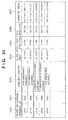
The database server 201 has the database 1999. This
database 1999 stores a transition 1915 of the number of
printed paper sheets, an average print rate 1916 per
cartridge, a cartridge delivery day 1917, a toner low signal
generation day 1918, a cumulative number 1906 of use days,
and a cumulative number 1907 of printed paper sheets for
each user. In addition, by transmitting data recorded in
the memory of the cartridge to the service center from PC
at a collection base, a toner out signal generation day 1908
for each cartridge, a toner low signal generation day 1909
for each cartridge, a use period 1910 for each cartridge,
a number 1911 of paper sheets used for each cartridge, and
data 1912 of the number of printed paper sheets for each
cartridge are also stored.
-
As the average print rate 1916 per cartridge, an
average print rate 1913 for each cartridge is stored, which
is calculated from the number 1903 of cartridges used, a
collection day 1904, and data 1905 of the number of printed
paper sheets per cartridge. The transition 1915 of the
number of printed paper sheets is stored as a transition
in each month by totaling the data 1905 of the number of
printed paper sheets in units of months.
-
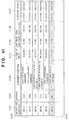
An average print rate 1919 per cartridge (obtained
in units of types of cartridges or the like), which is more
accurate than the average print rate 1913, and an average
period 1920 from the toner low state to the actual toner
out are obtained from the collected cartridge and stored
in the database 1999.
-
For prediction, first, a remaining number 1921 of
printable paper sheets is predicted from the average print
rate 1919 per cartridge, and a period 1922 to toner out is
predicted from the remaining number 1921 of printable paper
sheets. At this time, the predicted value can be corrected
using data such as the transition 1915 of the number of
printed paper sheets. An appropriate delivery day 1923 is
obtained from the resultant period 1922 to toner out and
a toner low signal generation day 1901, and an expected
exchange time is output. Exchange day candidates are
output to the user site, including the date/time at which
delivery is possible to the predicted toner out day, by
looking up the stock and delivery schedule.
-
Fig. 20 is a block diagram showing the contents of
correction processing for more accurately predicting the
toner out time. For example, assume that the PC 203 of the
service center receives a toner low signal on August 31.
Since the toner low signal contains the cartridge ID/serial
number, the remaining number of printable paper sheets is
calculated as 1,000 from the average print rate of a
cartridge of the same type. If the number of printed paper
sheets immediately before is 1,000 per month, the remaining
toner will be exhausted in one month, and the cartridge must
be exchanged before it.
-
Correction values are looked up at this time. As is
apparent from the transition 1915 of the number of printed
paper sheets for each month, the number of printed paper
sheets per month is 2,000 from September to December, and
the printing amount doubles this year as compared to the
last year. Apparently from these values, 4,000 paper
sheets may be printed per month from September.
-
When the number of sheets printable by the remaining
toner, 1,000, is converted into a period on the basis of
the estimated printing amount, the remaining toner may last
only for 1/4 month or about one week. Hence, as an expected
exchange time, September 7 a week after August 31 is
obtained. For the user, the period from the cartridge
deliverable day to September 7 is presented (transmitted)
as delivery/collection day candidates.
-
In the above way, the expected exchange time is
obtained first from the average value on the basis of the
data stored in the database, and the obtained expected
exchange time is corrected in accordance with the
periodical variation and recent tendency, which can also
be acquired from the database. Thus, an accurate toner out
day is predicted, and the expected day can be presented to
the user such that the cartridge can be exchanged before
that day. If the period for which printing can be performed
using the remaining toner is expected to be very long, the
period of cartridge delivery/collection days may be limited
to a predetermined number of days, e.g., one week including
the expected toner out day so that the toner can be used
up as much as possible. In this case, for example, if the
period for which printing can be performed using the
remaining toner is predicted to be one month, the final week
is presented to the user as delivery/collection day
candidates.
-
When the PC of the service center 101 receives the
cartridge ID/serial number and remaining toner amount
together with the toner low signal, the toner out day can
be more accurately predicted from the cartridge ID/serial
number and remaining toner amount. For example, when the
cartridge ID/serial number is known, the models of devices
in which the cartridge is being used can be limited. For
this reason, the average print rate and the number of
printed paper sheets can be obtained while limiting devices
that use the cartridge on the basis of the pieces of
information of the cartridge ID/serial number and remaining
toner amount obtained from the cartridge. When the average
print rate and the number of printed paper sheets are
corrected using pieces of information such as the
periodical variation and tendency managed by the database
1999, the toner out day can be more accurately predicted.
-
When the PC 203 of the service center 101 manages
delivered cartridges in units of users, which cartridge is
used by which device of which user can be discriminated.
When the database 1999 manages the toner consumption, print
rate, and the number of printed paper sheets for each user
or for each model of each user, pieces of information
including the average print rates, periodical variations,
and recent tendencies can be stored in units of devices
installed for each user. When the pieces of information
stored in units of users or devices are used like the
above-described database, toner out can be predicted.
-
As described above, since the cartridge
delivery/collection schedule can be determined by highly
accurately predicting the toner out time, the toner in the
cartridge can be used up as much as possible by matching
the cartridge exchange time with the toner out time. This
contributes to resources savings. In addition, since the
printing count charge scheme charges for the number of
printed paper sheets, the prime cost can be reduced by
decreasing the amount of toner unused and discarded. This
contributes to cost reduction or an increase in profit
margin.
<Charge Sequence>
-
Fig. 12 is a system flow chart showing a procedure
of charging for the number of printed paper sheets at the
user site. The charge sequence is assumed to be triggered
by data of the number of printed paper sheets which is
periodically transmitted from the user site. However,
this sequence may be started in accordance with a request
from the service center or triggered by a toner low signal.
Charge operation by the service center, including issue of
a bill, may be performed asynchronously with transmission
of data of the number of printed paper sheets from the user
site to the service center.
-
Referring to Fig. 12, a portion "user site" means
processing executed at the user site 102, and a portion
"service center" means processing executed by the PC 208
of the service center. In the processing by the user site
102, a step "device" is executed by the device having the
toner cartridge, and a step "host" is executed by the host
computer such as a PC connected to the device through cables
or networks. After the data of the number of printed paper
sheets is transmitted to the PC 203 of the service center
101, communication between the service center and the user
site is performed between the respective window terminals.
-
Referring to Fig. 12, data of the number of printed
paper sheets, which is generated after the preceding charge
sequence, is read by the device module from the device which
is included in the user site 102 and has an agreement of
printing count charge scheme, and transmitted to the
service center 101 ( steps 1201, 1202, and 1202a). Since
charging and cartridge exchange are asynchronously
performed, the data of the number of printed paper sheets
to be transmitted is obtained according to a procedure to
be described later.
-
When the device is connected to the remote
communication network 205 through a host, the host computer
temporarily receives the data of the number of printed paper
sheets (step 1203). For a manual scheme, the data is input
by the manager, or for an automatic scheme, the received
data is automatically transmitted to the service center
(step 1204 or 1205).
-
In the present invention, as a form of connection to
the remote communication network 205 through the host, the
device may be connected to the host through a cable or
through a network such as a LAN. Also, the host may have
a server function, and another host (host having no server
function) may be connected to the host having the server
function.
-
The PC 203 of the service center 101 receives the data
of the number of printed paper sheets (step 1206), and the
data is transferred to the service module 210 of the PC 203.
The service module 210 totalizes the numbers of printed
paper sheets of the respective devices in units of users
(step 1207), calculates the payable amount on the basis of
the totalized value (step 1208), and transmits the amount
to the user module 250 of the PC 208 together with pieces
of particulars information such as the number of devices
with agreement and the number of printed paper sheets (step
1209).
-
The window displayed at this time is shown in Fig. 16.
The particulars are displayed together with the payable
amount. To agree with this payable amount, the user clicks
the YES button. If there is any question, the user clicks
the NO button for inquiry or negotiation. Finally,
settlement is done by a predetermined method (step 1210).
Step 1210 can be executed as part of the series of processing
operations if it is settlement through a computer network.
However, if the predetermined method is not an electronic
settlement method but, e.g., payment to a bank account, the
processing by the service module 210 is ended without
executing step 1210.
-
Fig. 17B is a flow chart showing details of steps 1201
and 1202 of Fig. 12, which are executed by the device
modules 230 and 240 to transmit the number of printed paper
sheets from the user device. Fig. 17A shows the printing
count storage area in the RAM of the device. The storage
area includes a number 1711 of uncharged printed paper
sheets for toner cartridges used so far, which represents
the number of printed paper sheets for which the charge is
not paid, a number 1712 of charged printed paper sheets for
the currently attached toner cartridge for which the user
has already been billed the charge amount, and a number 1713
of printed paper sheets read out from the used cartridge
immediately before cartridge exchange.
-
To transmit the data of the number of printed paper
sheets from the device, the number of printed paper sheets
is read out from the memory of the cartridge, the value of
the number 1712 of charged printed paper sheets is
subtracted from the readout number of printed paper sheets,
and the difference value is stored as the number 1711 of
uncharged printed paper sheets (step 1701). The number of
uncharged printed paper sheets is transmitted to the
service center or host (step 1702). Finally, when it is
confirmed that the number of uncharged printed paper sheets
is transmitted, "0" is set in the number 1711 of uncharged
printed paper sheets, and the number of printed paper sheets
read out from the cartridge is set in the number of charged
printed paper sheets.
-
The flow chart shown in Fig. 17 is executed every
predetermined period such as one month by the timepiece
function of the device. Although not illustrated in
Fig. 12, in the present invention, an instruction for
transmitting information of the number of uncharged output
paper sheets of the device, which is stored in the PC 208,
may be transmitted from the PC 203 to the PC 208 every
predetermined period, and charge information such as the
number of output paper sheets may be acquired by the PC 203.
Also, in the present invention information such as the
number of uncharged output paper sheets of the device, which
is stored in the device itself, may be transmitted to the
PC 203 every predetermined period by the timepieces
function of the PC 208. When the cartridge is exchanged,
the device such as the printer 100 or facsimile apparatus
206 executes the procedure shown in Fig. 18. The procedure
shown in Fig. 18 is executed assuming that the cartridge
is probably exchanged when the cover of the cartridge
storage section of the device main body is opened and then
closed again or when the device is powered on. Whether the
cover of the cartridge storage section is open is detected
by a sensor. Immediately after the cartridge cover is
opened or in the processing sequence after the device is
powered off, the device reads out the data of the number
of printed paper sheets from the memory of the currently
attached cartridge and stores it as the number 1713 of
printed paper sheets of the cartridge.
-
After that, when the cartridge cover is closed or the
device is powered on, the cartridge ID/serial number is read
from the currently attached cartridge and compared with the
cartridge ID/serial number read and stored after cartridge
exchange (step 1801). The comparison result is determined
in step 1802. If YES in step 1802, the cartridge has not
been exchanged, and the processing is ended.
-
If NO in step 1802, the cartridge has been exchanged,
so the read cartridge ID/serial number is stored as the
current cartridge ID/serial number (step 1803).
-
The stored number of printed paper sheets is read out
from the number 1713 of printed paper sheets of the
cartridge (step 1804). A value obtained by subtracting the
value of the number 1712 of charged printed paper sheets
from the readout number of printed paper sheets is added
to the number of uncharged printed paper sheets (step 1805).
-
Then, "0" is set in the number 1712 of charged printed
paper sheets (step 1806).
-
With this processing, for the number of printed paper
sheets recorded in the cartridge, the number of printed
paper sheets for which the user has already been billed the
charge amount can be distinguished from the number of
printed paper sheets for which the user has not been billed
the charge amount yet. For this reason, in the charge
processing, the user can be billed a correct charge amount
based on the number of uncharged paper sheets.
-
Note that a new cartridge is substantially supplied
to the user without any charge.
-
In the above-described manner, the printing count
charge scheme of charging for the number of printed paper
sheets can be applied to a device such as a printer which
supplies toner by a toner cartridge. When the printing
count charge scheme is applied, payment can be done
asynchronously with operation such as cartridge exchange
or collection, and a charge system corresponding to the
printing amount can be implemented. Since the service side
such as a maker or seller can expect a continuous and stable
profit, business expansion can be expected. In addition,
since data collection for the printing count charge scheme
is done through a network, the labor can be reduced, and
highly accurate data can be quickly acquired.
-
Furthermore, linking with the management system for
accurately predicting the toner out time of the cartridge,
any increase in prime cost due to discard of unused toner
can be prevented, and the printing count charge scheme for
cartridges can be commercially successful.
-
On the user side, since a variation in print cost
decreases, and the charge can be simply checked or estimated
from the number of printed paper sheets, check of the amount
paid and budget formation for print cost are facilitated.
This contributes to an improvement of productivity of these
operations.
-
Note that the device may transmit the cartridge
ID/serial number together with the number of printed paper
sheets. In this case, the service center receives the
cartridge ID/serial number and stores the data in the
database shown in Fig. 20.
<Device Maintenance>
-
Fig. 21 shows a procedure when a malfunction occurs
in the user device. In this embodiment, since the user site
and service center are connected through a network, both
a malfunction notification and a repair request can be
transmitted through the network.
-
When malfunction information is generated by, e.g.,
detecting a malfunction by the user device, the device
transmits the malfunction information to the service center
directly through the remote communication network 205 when
the device is connected to the remote communication network
205, or to the host when the device is connected to the remote
communication network 205 through the host (step 2101).
-
If the device has no failed sensor or cannot detect
the malfunction, or the device is not connected to the
remote communication network, the operator manually inputs
the malfunction information directly to the remote
communication network 205 or to the host connected to the
remote communication network 205 (step 2102).
-
When the malfunction information is transmitted to
the host, the host receives the malfunction information
(step 2103), so the malfunction information is transmitted
to the service center manually by the operator (step 2104)
or automatically (step 2105).
-
In the service center, when the PC 203 receives the
malfunction information (step 2106), the service division
of the device maker or a repair agent is automatically or
manually notified of necessary information, and the
schedule is adjusted between the service center and the
service division or repair agent (step 2107). The adjusted
schedule is transmitted to the window terminal 208 of the
user site. When the schedule is further adjusted and
determined (step 2108), repairs are done in accordance with
the determined schedule. To adjust the schedule, data may
be exchanged between the service center and the service
division or the like in step 2107 or the user site in step
2108.
-
Fig. 22A shows a window displayed when the service
center notifies the user site of the schedule in step 2108.
The user selects schedules in this window and returns them
to the service center.
-
Fig. 22B shows a window showing information to be
transmitted from the service center to the user site in
order to check the contents of a malfunction in advance.
The user selects a corresponding malfunction content from
the displayed candidates and returns it to the service
center. The window shown in Fig. 22B can be displayed
either at or before the schedule adjustment. When the user
is made to send the malfunction content before adjustment,
the degree of malfunction can be reflected on the schedule.
-
In this way, malfunction notification and repair
schedule adjustment can be done through the network. A
serviceman who checks and repairs the printer is dispatched
from the service center to the user in accordance with the
adjusted schedule. At this time, the user is basically
billed no charge except that corresponding to data related
to the number of printed paper sheets.
-
As described above, in the printing count charge
scheme according to this embodiment for use of a printer
using a detachable cartridge which accommodates at least
toner and a developing unit, data related to the number of
paper sheets printed by the printer and data related to the
remaining toner amount in the cartridge, which are output
from the printer having a cartridge attached thereto, are
supplied to the service center through the remote
communication means, and the service center bills the user
of the printer a charge corresponding to the data related
to the number of printed paper sheets supplied through the
remote communication means and supplies to the user a new
cartridge to be attached in place of the cartridge in the
printer on the basis of the data related to the remaining
toner amount basically without billing the user the charge.
-
The charge corresponding to the data related to the
number of printed paper sheets is included in the
maintenance service charge for the printer. In addition,
data related to a malfunction of the printer is supplied
to the service center through the remote communication
means, and the service center dispatches a serviceman who
checks and repairs the printer on the basis of the data
related to the malefaction of the printer, which is supplied
through the remote communication means, basically without
billing the user any charge except the charge corresponding
to the data related to the number of printed paper sheets.
-
Furthermore, the function of the service center
includes a delivery function such as a cartridge delivery
agent. The used cartridge is collected when a new cartridge
is supplied.
<Effects of First Embodiment>
-
According to the cartridge management system of the
above-described embodiment, the following effects can be
obtained.
- (1) When a toner low signal is generated, the toner
out time is predicted, and the cartridge is exchanged at
the predicted time. For this reason, the toner in the
cartridge can be used up, and this contributes to resource
savings and prime cost reductions.
- (2) Since the cartridge can be exchanged immediately
before toner out in the cartridge, the downtime of the
device such as a printer due to toner out can be eliminated.
- (3) Since the cartridge is delivered to the user
immediately before toner out in the cartridge, the user need
not stock or store spare cartridges or used cartridges.
- (4) Since delivery and collection of cartridges are
combined, the user need not bring a used cartridge to the
maker or shop. In addition, when the new cartridge is
exchanged with the used cartridge immediately after
delivery, the used cartridge can be reliably collected.
- (5) A plurality of devices at the user site can be
charged together. For this reason, charging and
maintenance can be done in units of users.
- (6) Since the cartridge itself has a memory to store
printing record data such as the number of printed paper
sheets, the data can be stored in a database, and toner out
can be accurately predicted using the data.
- (7) Since the cartridge itself has identification
data such as an ID representing the cartridge type or a
serial number to uniquely identify the cartridge, it can
be checked whether the cartridge has been exchanged. It
can be checked using these identification data whether it
is a cartridge delivered by a printing count charge scheme
agreement, so any illicit use of the cartridge can be
prevented. In addition, the cycle of reuse/recycle can be
managed.
- (8) Since the cartridge itself has data, the number
of printed paper sheets or the like can be grasped from the
data of the cartridge even when it is detached from the
device.
- (9) Since data are systematically managed by the
service center, the print rate and exchange time can be more
accurately calculated.
-
[Second Embodiment]
-
As the second embodiment, a system using a cartridge
having no memory will be described. Only different points
between this system and the first embodiment will be
described. Hence, the overall arrangement is the same as
in Figs. 1 and 2, and the arrangement of a device is also
the same as in the first embodiment except that the
cartridge has no memory.
<Charge Sequence>
-
Fig. 23 shows a data area prepared in the memory of
a device charged by the printing count charge scheme of this
embodiment. Basically, the data are the same as those held
in the memory of a cartridge, though data unique to the
cartridge is excluded. A total number 2300 of
printed/jammed paper sheets represents the number of
printed paper sheets and the number of paper sheets print
of which has failed. A number 2301 of printed/jammed paper
sheets for A3 and a number 2302 of printed/jammed paper
sheets for A4 represent the numbers of paper sheets for the
respective sizes. These values are incremented by one
every time the device prints one page of a paper sheet with
a corresponding size.
-
A service center address 2303 represents the address
of a transmission destination of the number of printed paper
sheets or a toner low signal. This field is used when the
device is directly connected to a remote communication
network 205. A cartridge type ID 2304 is used to notify
the service center of the cartridge type from the device.
The contents in the fields 2303 and 2304 are rarely changed
and therefore can be recorded in a ROM. In the present
invention, the device ID stored in a memory of the device
can be also applied instead of the cartridge ID 2304.
-
Fig. 24 is a system flow chart showing the charge
procedure executed in this embodiment in place of that shown
in Fig. 12 of the first embodiment.
-
The device module reads out the data 2300 to 2302 of
the numbers of printed paper sheets shown in Fig. 23
periodically or in accordance with a request from the
service center, and transmits the data to the remote
communication network 205 or the host connected to the
device in accordance with the connection destination (step
2401). When transmission is confirmed, "0" is set to the
read out data 2300 to 2302 of the numbers of printed paper
sheets.
-
Steps 2403 to 2410 are the same as steps 1203 to 1210
in Fig. 12, and a detailed description thereof will be
omitted.
-
As described above, even when the cartridge has no
memory, the service center can charge for the number of
printed paper sheets in units of devices. Since this
sequence is also effective for a device using a cartridge
having a memory, the procedure shown in Fig. 24 can be used
in place of that shown in Fig. 12 of the first embodiment.
Only the processing on the device side is different Fig. 12
and Fig. 24. Hence, when the procedure in Fig. 12 is
applied to a device using a cartridge having a memory, and
the procedure in Fig. 24 is applied to a device using a
cartridge having no memory, this system can cope with even
a user site having devices of both types.
<Prediction for Toner Out>
-
In this embodiment, the sequences of notification and
adjustment of a cartridge exchange schedule, which are
triggered by generation of a toner low signal by the device,
are almost the same as in Figs. 10 and 11 of the first
embodiment. However, since data for each cartridge cannot
be held, the serial number of a cartridge is not transmitted
together with the toner low signal. In addition, since data
to be reflected on the database are different from those
of the first embodiment, the prediction method is also
different.
-
Fig. 25 is a block diagram showing the procedure of
predicting the toner out time, which is executed by an
analyzing system 210 in step 1104 in Fig. 11 and used as
a reference for determining the delivery/collection
schedule.
-
The analyzing system has a database 2599. This
database 2599 stores a transition 1915 of the number of
printed paper sheets, an average print rate 1916 per
cartridge, a cartridge delivery day 1917, a toner low signal
generation day 1918, a cumulative number 1906 of use days,
and a cumulative number 1907 of printed paper sheets for
each user.
-
As the average print rate 1916 per cartridge, an
average print rate 1913 is stored, which is calculated from
the number 1903 of cartridges used, collection day 1904,
and data 1905 of the number of printed paper sheets per
cartridge. The transition 1915 of the number of printed
paper sheets is stored as a transition in each month by
totaling the data 1905 of the number of printed paper sheets
in units of months.
-
For prediction, first, a remaining number 2501 of
printable paper sheets is predicted from the average print
rate 1919, and a period 2502 to toner out is predicted from
the remaining number 2501 of printable paper sheets. At
this time, the predicted value can be corrected using data
such as the average print rate 1916 and the transition 1915
of the number of printed paper sheets in the past. An
appropriate delivery day 2503 is obtained from the
resultant period 2502 to toner out and a toner low signal
generation day 1901, and an expected exchange time is output.
Exchange day candidates are output to the user site,
including the date/time at which delivery is possible to
the predicted toner out day, by looking up the stock and
delivery schedule.
-
Fig. 26 is a block diagram showing the contents of
correction for more accurately predicting the toner out
time. For example, assume that the service center receives
a toner low signal on August 31. From the number of
printable paper sheets obtained from the immediately
preceding average print rate of per cartridge, the
remaining toner will be exhausted in one month, and the
cartridge must be exchanged before it.
-
Correction values are looked up at this time. As is
apparent from the average print rate 1916 per cartridge and
the transition 1915 of the number of printed paper sheets
for each month in the past, the print rate rises to 10% from
September to November. The average print rate from
September to November is almost three times that
immediately before. That is, there are only 10 days from
toner low signal generation to toner out. Hence, the time
limit for delivery of a reserve cartridge is set at
September 10 that is 10 days after August 31 as the toner
low signal generation day. For the user, the period from
the cartridge deliverable day to September 10 is presented
as delivery/collection day candidates.
-
In the above way, an accurate toner out day can be
predicted, and the expected day can be presented to the user
such that the cartridge can be exchanged before that day.
If the period for which printing can be performed using the
remaining toner is expected to be very long, the period of
cartridge delivery/collection days may be limited to a
predetermined number of days, e.g., one week including the
expected toner out day so that the toner can be used up as
much as possible. In this case, for example, if the period
for which printing can be performed using the remaining
toner is predicted to be one month, the final week is
presented to the user as delivery/collection day
candidates.
-
As described above, since the cartridge
delivery/collection schedule can be determined by highly
accurately predicting the toner out time, the toner in the
cartridge can be used up as much as possible. In addition,
since the printing count charge scheme charges for the
number of printed paper sheets, the prime cost can be
reduced by decreasing the amount of toner unused and
discarded. This contributes to cost reduction or an
increase in profit margin.
-
An analyzing system using both the prediction scheme
shown in Fig. 19 and that shown in Fig. 25 can also be built.
In this case, for a cartridge having no memory, toner out
is predicted using the method shown in Figs. 25 and 26, and
for a cartridge having a memory, toner out is predicted
using the method shown in Figs. 19 and 20.
<Effects of Second Embodiment>
-
According to the cartridge management system of the
above-described embodiment, the following effects can be
obtained.
- (1) When a toner low signal is generated, the toner
out time is predicted, and the cartridge is exchanged at
the predicted time. For this reason, the toner in the
cartridge can be used up, and this contributes to resource
savings and prime cost reductions.
- (2) Since the cartridge can be exchanged immediately
before toner out in the cartridge, the downtime of the
device such as a printer due to toner out can be eliminated.
- (3) Since the cartridge is delivered to the user
immediately before toner out in the cartridge, the user need
not stock or store spare cartridges or used cartridges.
- (4) Since delivery and collection of cartridges are
combined, the user need not bring a used cartridge to the
maker or shop. In addition, when the new cartridge is
exchanged with the used cartridge immediately after
delivery, the used cartridge can be reliably collected.
- (6) Unlike the first embodiment, a charge system and
delivery/collection system based on the printing count
charge scheme can be built using a conventional device using
a cartridge having no memory.
- (7) Since data are systematically managed by the
service center, the print rate and exchange time can be more
accurately calculated.
-
[Third Embodiment]
-
As the third embodiment, a system which excludes a
delivery agent entrusted with delivery operation on a
network from the system of the first embodiment will be
described. The arrangement of the system and the
arrangement of each device are the same as in Figs. 2 to
9 of the first embodiment.
-
Fig. 27 schematically shows the management procedure
of the third embodiment. The same numbers as in Fig. 1
denote the same messages in Fig. 27.
-
If toner decreases to a predetermined amount or less,
i.e., a toner low occurs in a printer 100a or 100b or
facsimile apparatus 206 at a user site 102, it is detected
by the sensor incorporated in the cartridge. A service
center 101 is notified of this state as a toner low signal
(1) from PC 208 or directly from the device of the user site
102. Although the service center is simply mentioned here,
more specifically, the notification destination of a PC 203
or the like included in the service center 101.
-
Upon receiving this notification, the service center
101 transmits a cartridge delivery/collection notification
(4) to the user site 102. However, as will be described
later, this notification is not simply transmitted but
includes a sequence for schedule adjustment with the user.
-
The service center 101 delivers (10) a new cartridge
to the user site 102 in accordance with the schedule
determined by the cartridge delivery/collection
notification (4), and simultaneously, collects (11) the
used cartridge and carries the collected cartridge to a
collection base 104.
-
At the collection base 104, necessary data are read
out from the memory of the collected used cartridge, and
the readout data are stored in the database managed by the
service center 101. The readout data are transmitted to
the service center 101 as cartridge data (12).
-
Asynchronously with this cartridge delivery, data
(8) of the number of printed paper sheets based on the
printing count read out from a memory 820a of the cartridge
is transmitted from the user site 102 to the service center
101.
-
The service center 101 calculates a charge
corresponding to the received data of the number of printed
paper sheets and transmits a bill (9) to the user site 102.
The user pays the service center the payable amount by a
payment method determined independently. The payee at
this time may be an independently determined payee other
tan the service center.
-
As described above, triggered by an event
notification (toner low notification) from the user site
102, the service center 101 realizes, through the remote
communication network 205, collection of necessary data
from the user site, arrangement for delivery/collection of
cartridges and generation of charge information, and
sending a notification concerning the arranged schedule and
charge information to the user site.
<Sequence of Notification and Adjustment of Cartridge
Exchange Schedule>
-
In the arrangement shown in Fig. 27, the procedures
of transmitting a toner low signal from the user site 102
to the service center 101 and receiving the toner low signal
by the service center 101 are the same as in Fig. 10 of the
first embodiment. However, processing in the service
center which has received the toner low signal is performed
as in Fig. 28.
-
Referring to Fig. 28, first, the processing branches
in step 1101 depending on whether the data is automatically
or manually input to the analyzing system of the service
center 101. Step 1101 need not always be done in the service
center. This is a pseudo step for expressing a processing
procedure according to the arrangement of the service
center. Actual processing in the service center starts
from step 1102 or 1103 depending on its arrangement. In
this embodiment, the analyzing system is implemented on the
PC 203 by executing an analysis program based on a procedure
to be described later by looking up the database in a
database server 201.
-
In the manual input scheme, a window for notifying
the person in charge of operation of reception of the toner
low signal is displayed in step 1102, and the person in
charge inputs the information to the analyzing system to
manage the delivery schedule.
-
In the automatic input scheme, the received toner low
signal and the data read out from the cartridge are directly
input to the analyzing system (step 1103).
-
When the data are input to the analyzing system, the
date of toner out is predicted by the analyzing system, and
delivery day candidates are determined on the basis of the
toner out day (step 1104). This prediction procedure will
be described later. Subsequent steps may be manually
executed, though they are automated in this case.
-
When the delivery day candidates are determined, the
user is notified of the days as an expected exchange time
(step 1108).
-
Upon receiving this notification, the user interface
(UI) window shown in Fig. 13 is displayed at the user site
102 by a PC 208 as a window terminal. When the operator
inputs an acknowledge (OK) for cartridge exchange in this
window, the window is switched to that shown in Fig. 14.
In this window, the operator inputs desired date and time
from the expected exchange times.
-
The input designated day is transmitted to the
service center 101. The service center 101 notifies the
user of expected delivery/collection date and time
determined on the basis of the designated day and requests
final check (step 1109). Fig. 15 shows a window displayed
on the user side at this time.
-
In accordance with the date and time determined by
the above procedure, a serviceman or IT staff for
maintenance or a delivery van for simply delivering goods
is dispatched from the service center 101 to
deliver/collect the cartridge and, as needed, execute
maintenance of the device. The staff to be dispatched and
operation contents depend upon the agreement between the
user and the shop or maker that operates the service center.
-
In addition, the charge scheme (printing count charge
scheme) depending on the number of printed paper sheets is
asynchronous with delivery/collection of cartridges and
therefore functions as in the first or second embodiment.
-
As described above, in this embodiment, a system
which does not entrust a delivery agent with delivery
operation on a network can be built. In this case, the same
effects as in the first or second embodiment can be
obtained.
[Fourth Embodiment]
-
The basic arrangement of the system according to the
fourth embodiment is the same as in the first embodiment
except that the user site includes a stockmanagement system.
As shown in Fig. 29, a stock management system 260 is
implemented by executing a predetermined program by PC 4
or the like at a user site 102. This stock management system
260 also manages the internal stock of toner cartridges and
links with the cartridge management system. The computer
on which the stock management system runs must be able to
directly or even indirectly access a remote communication
network 205.
-
Fig. 30 shows the procedure of transmitting and
receiving a toner low signal from the user site 102 and
receiving the toner low signal by a service center 101 in
the fourth embodiment. First, a toner low is detected in,
e.g., a printer 100a or 100b or facsimile apparatus 206
shown in Fig. 2, and the information is output as a toner
low signal by the device module in step 2901. If the device
is the facsimile apparatus 206 or printer 100b, the toner
low signal is transmitted (S2901a) to a PC 208 on which the
internal stock management system runs as the input signal
to the stock management system 260.
-
If the device is a printer locally connected to the
host, like the printer 100a, a toner low signal is issued
to the host. In this case, the host receives the toner low
signal in step 2902. After that, the toner low signal is
transmitted from the host to the internal stock management
system 260.
-
Upon receiving the toner low signal, the stock
management system 260 determines the type of cartridge used
by the device from the information of the transmission
source of the toner low signal or information of the device
ID/serial number or the cartridge type ID/serial number
transmitted together with the toner low signal, and
determines whether there is a stock (step 2903). If there
is a stock, information representing it is displayed on the
display of the PC 208 to call for user's attention (step
2904).
-
If it is determined that no stock is present, the toner
low signal is transmitted from the stock management system
260 to the service center 101 in accordance with the
connection form between the toner low signal transmitting
device and the remote communication network 205. When the
device can directly access the remote communication network
205, the toner low signal is directly transmitted to the
service center (step 2907). When the device is connected
through the host computer, the toner low signal is
transmitted from the host to the service center 101 (step
2906). When the device cannot access the remote
communication network online, the toner low signal is
transmitted to the service center 101 by manual input by
the operator (step 2905).
-
The thus transmitted toner low signal is received by
the service center 101 (step 2908), and then, processing
is executed by a service module 210 and user module 250
according to the same procedure as in Fig. 11.
-
With the above process, when the user manages the
stock, a cartridge management system which uses the stock
of the user can be built, in addition to the effects of the
first and second embodiments.
[Fifth Embodiment]
-
In the first embodiment, processing of charging for
the number of output paper sheets printed at the user site
has been described with reference to Fig. 12, and device
maintenance processing of containing a charge
corresponding to the information related to the number of
printed paper sheets in the maintenance service, and
instructing to dispatch a serviceman who checks and repairs
the printer basically without billing the user any charge
except the charge corresponding to the information related
to the number of printed paper sheets has been described
with reference to Fig. 21.
-
In the fifth embodiment, a charge system capable of
offering a more convenient maintenance service to the user
will be described.
-
Fig. 32 shows an outline of transmission/reception
of data related to agreement processing between a user site
and a service center. The user site and service center
correspond to those in Fig. 1, respectively. In the
processing operations in steps of Fig. 32, processing on
the user site side is executed by the PC 208, and processing
on the service center side is executed by the PC 203. The
functions of the PCs 208 and 203 are the same as those
described in the first to fourth embodiments, and their
block diagrams correspond to Fig. 3. The processing in the
PCs 208 and 203 is implemented by causing the CPU 301 to
control processing based on program codes stored in any one
of the ROM 307, RAM 302, and HD 303. The PC 203 cooperates
with the database server 201 so that data management and
data offer (data transmission to the user site) are
performed by the CPU 301 on the basis of the data contents
stored in the database server 201. The functions of the
present invention can be implemented regardless of whether
the PC 203 and database server 201 are physically separated
or integrated as long as the functions of the present
invention can be implemented by cooperation of the PC 203
and database 201.
-
The processing on the user site 102 need not always
be executed by only the PC 208. In the present invention,
the same function (e.g., function of allowing two-way
communication with an external device through the remote
communication network 205) as that of the PC 208 may be
prepared in the device such as the printer 100a or 100b or
facsimile apparatus 206 so that the device executes the
processing. In this case, the device has the same block
arrangement as in Fig. 6 or 7, and processing based on
program codes stored in the storage section of the device
is implemented under the control of the CPU 601 or 701.
-
The respective processing operations will be
described below with reference to the flow chart of Fig. 32
and other drawings.
-
An ID is transmitted from the user site in step S3201.
-
The ID corresponds to an agreement ID which is linked
with a specific user to specify agreement information for
that user. A user ID will be described below.
-
The ID transmitted in step S3201 is information input
to the PC 208 or a device through the display window. In
the present invention, the PC 208 or 203 or a device
preferably has a browser function capable of processing a
language such as HTML or XML. The window for inputting the
ID is generated by the PC 203 and transmitted when the user
designates a URL or file specifying information. The
window is displayed on the display section of the PC 208
or device. When a window for prompting the user to input
login information is displayed before the display of the
ID input window, any illicit access can be prevented. The
function of the present invention is not limited to the
browser function, and any other function for supporting
two-way communication can be used.
-
Here, ID information transmission from the user site
to the service center is executed by a device module 240,
a device module 230, a user module 250 of the host computer
or the stock management system 260 described above, which
transmits data from the device to the service center.
-
Agreement information corresponding to the ID
transmitted from the user site is searched for in step
S3202.
-
The information found by the search in step S3202 is
transmitted from the service center to the user site in step
S3203.
-
Display processing for the information transmitted
in step S3203 is executed by the device on the user site
side in step S3204. This display processing is done on a
display section provided on a PC 208, printer 100a, or the
like at the user site. The display section corresponds to
a display 304 in Fig. 3, an operation section 607 in Fig. 6,
or an operation section 707 in Fig. 7.
-
Figs. 33 to 41 shows
-
The display examples (display information) shown in
Figs. 33 to 41 discribed later show data managed in a
storage section of a database server 201, PC 203, or the
like on the service center side. These data are transmitted
to the user site side and displayed on the display section
of printers 100a and 100b, facsimile apparatus 206, or PC
208. The data shown in Figs. 13-16, 22A and 22B are also
displayed as the same manner as described above.
-
Fig. 33 shows a display example in step S3204 in which
agreement contents (3306) for each device model (3305) are
displayed. A change in agreement contents for each device
will be described below. The device type 3305 in Fig. 33
is not limited to the printer. A device such as a facsimile
apparatus, copying machine, or personal computer can also
be assumed. Also, the display examples shown in Figs. 34-41
are not limited to a printer.
-
Fig. 34 also shows a display example in step S3204
in which, as pieces of display information, user devices
(3401), IDs (3402) corresponding to the devices, agreement
situations (3403), the numbers (3404) of output paper
sheets of the devices, output unit prices (3405) per print,
which correspond to the agreement situations, charge
amounts (3406) based on the numbers of output paper sheets
and the output unit prices per print, and agreement periods
(3407) corresponding to the devices are displayed. The
number (3404) of output paper sheets of each device has a
form corresponding to the number of uncharged paper sheets.
In the present invention, display of the total number of
printed paper sheets in the agreement period, and the total
number of printed paper sheets for a predetermined period
such as a month or week is also assumed. Since the pieces
of display information as in Fig. 34 can be browsed at the
user site, the user can clearly know which device need
update of the agreement in updating the agreement. The way
for the obtaining the number 3404 of output paper sheets
of each device and each expendable at the service center
is the same as that described in the first, second, and third
embodiments, and a detailed description thereof will be
omitted.
-
In step S3205, information for specifying devices
covered by the agreement processing is input in accordance
with an instruction input to a check box 3304 shown in
Fig. 33.
-
In step S3206, the information of the devices input
in step S3205 is transmitted from the user site to the
service center together with the ID (ID in step S3201).
-
In the service center, detailed information based on
the ID and information for specifying devices covered by
the agreement, which are transmitted from the user site in
step S3206, is searched for, and the search result is
transmitted to the user site (S3207).
-
Fig. 35 shows a display example of information at the
user site, which is transmitted in step S3207. The display
example shown in Fig. 35 indicates a result of selection
of the LBP-A2 (this means the second LBP) in Fig. 33. A
portion 3503 shows that ""spot maintenance agreement" is
made for the LBP-A2 until December 31, 2001". A check box
3505 is turned on by the user to select agreement contents
to be changed. When the user inputs to this check box, a
mark which can be identified by the user is added to the
window. An instruction button 3507 is clicked to display
detailed information of the agreement contents. When this
instruction button is clicked, details of the agreement
contents are displayed on the window. To display such
detailed contents, an instruction button 3307 is also
displayed in Fig. 33. This allows the user to check the
agreement contents in advance.
-
Figs. 36 and 37 show data stored and managed by the
database server 201 of the service center. These data are
transmitted to the user side (S3210) and browsed in
accordance with instruction information and ID of the
"details" button 3505 or 3507 in Fig. 35 or 33 (S3209)
described above. Details of agreement contents shown in
Figs. 36A and 36B will be described here.
(Spot Maintenance Agreement)
-
A spot maintenance agreement includes only the charge
for use of CRGs (cartridges). Charges for dispatch, repair,
and components are paid every time repair is done.
(Basic Maintenance Agreement)
-
In a basic maintenance agreement including not only
the charge for use of CRGs but also the periodical visit
maintenance cost, repair is done without any charges for
it, e.g., charges for dispatch, repair, and components,
independently of the number of times of repair unless the
charge for repair in the agreement period exceeds the upper
limit. Any charge beyond the upper limit is paid as an
expense. Referring to Fig. 36B, the upper limit amount for
each model is stored and managed by the database server 201,
as in Fig. 34.
(Comprehensive Maintenance Agreement)
-
In a comprehensive maintenance agreement including
not only the charge for use of CRGs but also the periodical
visit maintenance cost during the agreement period, repair
is done without any charges for it, e.g., charges for
dispatch, repair, and components, independently of the
number of times and amount of repair, without exception.
-
The user can select/change the agreement conditions
in units of arbitrary periods. For example, the user can
select the spot maintenance agreement in the first year from
purchase of a printer assuming that the malfunction
frequency is low, the basic maintenance agreement in the
second year, and the comprehensive maintenance agreement
from the third year.
-
The types and contents of agreements are not limited
to these three types. For example, such an agreement can
also be made that an instruction button for selecting
whether an option for an image forming apparatus, such as
an HD or sorter used for scanner or reserved printing, is
to be used is provided on the window shown in Fig, 33 or
the like, and the charge for use of the option is included
in the charge amount of the number of output paper sheets.
In this case, a charge table is assumed in which data is
stored and the charge for use of the option is additionally
made to correspond to the amount per print in the charge
table shown in Fig. 37 (to be described later).
-
Fig. 37 shows data representing the charge amount per
printed and output paper sheet according to the agreement
contents. Charge amounts per printed and output paper
sheet for the respective maintenance agreements
corresponding to the LBP-A, B, C, and D are shown. As
described above, there are both charge amount in the charge
table, which includes or does not include the maintenance
cost per print. When the maintenance cost is included, the
amount is large. When the information for specifying the
device is transmitted to the service center in step S3206,
the convenience for the user can be improved by transmitting
only charge table display information corresponding to the
specified device from the service center to the user site
as information to be browsed by the user.
-
In the present invention, the charge amount to the
user is calculated by the service center in accordance with
the number of printed and output paper sheets of the image
forming apparatus and the amount per print obtained from
the charge table as show in Figs. 34 and 37. Acquisition
of the information of the number of printed and output paper
sheets of the image forming apparatus at the user site by
the service center is the same as that described in Fig. 12,
17B, 24, or 27 of the first to the third embodiments, and
a detailed description thereof will be omitted.
-
The data shown in Figs. 36 and 37 can be displayed
either simultaneously or selectively. Although not
illustrated, when a "return" instruction button or the like
is prepared to return the window to that immediately
precedingly browsed, the display can be returned to the
window in Fig. 33 or 35.
-
When the "details" button is not clicked in step S3208
(NO in step S3208), or after processing in steps S3209 and
S3210 is executed, agreement information which specifies
the type of agreement in accordance with the instruction
through the window shown in Fig. 35 by the user is input
in step S3211.
-
In step S3212, agreement update information
(corresponding to an input to a button 3509 in Fig. 35) is
transmitted from the user site to the service center. This
agreement update information contains at least information
for specifying a maintenance form for a given device, which
is generated through the window shown in Fig. 35, and an
ID. Upon receiving the information transmitted in step
S3212, the service center transmits information for
designating the agreement period to the user site (not
shown). Fig. 38 shows a display example.
-
In step S3213, when the agreement period is input
through a dialog box 3804 in Fig. 38, and an "OK" button
3806 is clicked, period designation information for the new
agreement is transmitted from the user site to the service
center together with the ID information and the information
specifying the device and the type of agreement.
-
Agreement check window information in step S3213 is
transmitted from the service center to the user site in step
S3214. Fig. 39 shows a display example at the user site.
If the user agrees with it (click on an approval button 3905
in Fig. 39), information representing approval is
transmitted from the user site to the service center.
-
Upon receiving the approval information, the service
center transmits information as shown in Fig. 40 to the user
site (not illustrated in the flow). This display
information contains instruction button information (4005)
for executing printing. When this button is clicked,
printing corresponding to the displayed information is
executed. For this printing, when the device which is
displaying the information in Fig. 40 is a personal
computer (PC), a printer or the like connected to the PC
executes output processing, and when the device which is
displaying the information in Fig. 40 is a device such as
a printer apparatus, the apparatus executes output
processing.
-
Agreement information management in the server after
the processing shown in Fig. 40 will be described. When
the agreement contents of the user are finally changed in
Fig. 40, or a change will be made in a designated period,
the window shown in Fig. 34 is changed to contents including
the new agreement contents, and the contents of data
corresponding to them are also changed. The changed data
are stored in the storage section of the database server
201 or PC 203 on the service center side and can also be
browsed by the user.
-
Referring to Fig. 35, as agreement information for
the LBP-A2, the "spot maintenance agreement" is made until
December 31, 2001. When the user instructs to make the
"basic maintenance agreement" from January 1, 2002 to June
30, 2002 through the user interfaces shown in Figs. 35, 38,
and 39, the display in Fig. 34 is changed to that in Fig. 41.
The pieces of information stored in the storage section of
the database server 201 or PC 203 are also changed to those
shown in Fig. 41. When the database server 201 or PC 203
recognizes that the model is LBP-A, and the "spot
maintenance agreement" is changed to the "basic maintenance
agreement", the storage table in Fig. 37 is looked up, the
unit price per print is changed from 10 yen to 13 yen, and
data as shown in Fig. 41 are created and managed. Referring
to Fig. 41, a model (4108) with an agreement and a model
(4109) for which an agreement is to be made are displayed
such that they can be identified. Data corresponding to
them are stored in the database server 201 or PC 203. This
embodiment also assumes to discernibly display models for
which agreements have matured.
-
Management tables as shown in Figs. 34 and 41
described above are stored and managed by the database
server 201 or PC 203. In this arrangement, use situation
information such as the number of printed paper sheets
transmitted from the user site together with the IDs is
received, and information of the payable amount is
transmitted at every predetermined period to the user on
the basis of the received number of printed paper sheets
of each ID and the tables shown in Figs. 34 and 41. A
display example displaying information of payable amount,
which is displayed for the user, corresponds to the display
example shown in Fig. 16.
-
Examples of IDs to be transmitted from the user site
together with the use situation information are a user ID,
model ID (machine ID), and agreement ID. These pieces of
ID information are stored in a nonvolatile memory provided
in a cartridge or a nonvolatile memory provided in an image
forming apparatus, or a storing section in PC 208, and these
ID information specify of which use status information
corresponds to each device.
-
The mechanism for transmitting from the user site to
the service center use situation information such as the
number of output paper sheets of each image forming
apparatus ( printer 100a or 100b, or facsimile apparatus
206) or each expendable together with the ID is the same
as that described in Fig. 12, 17B, 24, or 27 of the first
to third embodiments. That is, in the present invention,
the use situation information may be transmitted from the
PC 208 together with the ID or from the device main body
together with the ID. The ID transmitted together with the
use situation information of the image forming apparatus
or expendable is preferably the same as an ID (user ID) for
specifying agreement information for a specific user in
step S3201 of FIG. 32. However, the present invention can
also be achieved even with another ID.
-
Other application examples of the above fifth
embodiment will be described below.
- (1) In the description of steps S3201 to S3204 of
Fig. 32, a user ID is exemplified as an ID for specifying
agreement information for a user. However, the present
invention is not limited to the user ID and can also be
applied to, e.g., "ID of the device main body", "expendable
ID" of a toner cartridge or the like, or "agreement ID
corresponding to a specific device or expendable". For
example, when the ID of the device main body, the expendable
ID, or the agreement ID corresponding to a specific device
or expendable is applied to the ID to be transmitted from
the user site to the service center in step S3201 of Fig. 32,
the processing operations in the respective steps of
Fig. 32 are executed for the specific device or expendable.
This is useful, e.g., when the model whose agreement is to
be changed is specified in advance.
- (2) In the display example in step S3204, the
agreement contents corresponding to the device main body
of the image forming apparatus are displayed. However, in
the present invention, the agreement contents for each
expendable (e.g., cartridge) may also be displayed by
linking the expendable ID with the ID (user ID) transmitted
in step S3201. The ID of each expendable is managed by the
database server 201 in a link to the user ID. The expendable
used by the user can be searched for by the CPU 301 on the
basis of the user ID, and agreements are managed in units
of expendable IDs. In combination with the mechanism for
acquiring use situation information such as the number of
printed/output paper sheets of each expendable by the
service center, which is described in the first to third
embodiments, charging per print is executed in accordance
with the agreement contents for a specific expendable.
Additionally, when an expendable has a storage means for
storing an ID, the expendable ID can be recognized by the
device to which the expendable is attached even when it is
used by a plurality of devices covered by the agreement.
For this reason, in the present invention, the agreement
and use situation of an expendable used by a plurality of
devices can be managed. As described above, when the ID
of each expendable is managed, the ID in each step of Fig. 32
corresponds to the expendable ID, and each display window
is displayed not for devices but for expendables.
- (3) When the database server 201 installed in the
service center manages pieces of information including the
use situation, malfunction situation, and use period of the
image forming apparatus of a specific user, generates or
searches for appropriate maintenance agreement information
among those of which shown in Figs. 36A and 36B in accordance
with the managed information, and notifies the user of the
maintenance agreement information, a maintenance service
according to the exhaustion state of the image forming
apparatus can be easily offered to the user. For example,
malfunction information of the user device (e.g., a
printer), as described with reference to Fig. 21 of the
first embodiment, can be stored in the database server 201,
and the user can be notified of appropriate agreement
contents in advance in accordance with the model and
malfunction situation.
-
-
In the present invention, as a service form, a
plurality of agreements such as the "comprehensive
maintenance agreement", "basic maintenance agreement", and
"spot maintenance agreement" shown in Fig. 35 can be
automatically switched. For example, when appropriate
agreement information corresponding to the use situation
(the total number of printed and output paper sheets and
various malfunction situations) of each device model is
stored in the database server 201 in advance, and
malfunction information of the user device as described
with reference to Fig. 21 is received, an appropriate
maintenance agreement can be automatically offered to the
user. Furthermore, when the maintenance agreement
contents are automatically changed, and e-mail for
notifying the user that the agreement information storage
contents in the database server 201 are updated is
transmitted to prompt the user to check it, the maintenance
agreement can be automatically changed with user's check.
<Effects of Fifth Embodiment>
-
According to the cartridge management system of the
above-described embodiment, the following effects can be
obtained.
- (1) Since the charge amount per paper sheet printed
and output from the device includes the maintenance cost,
a system which flexibly copes with a change in maintenance
agreement contents by the user can be provided. When the
charge table as shown in Fig. 37 is prepared in the service
center, the charge per printed and output paper sheet can
be set in units of devices, expendables, and users, so a
system for offering a maintenance agreement that meets each
user's requirement can be built.
- (2) The user can arbitrarily select a plurality of
agreement conditions such as the spot maintenance agreement,
basic maintenance agreement, and comprehensive maintenance
agreement through the user interfaces shown in Figs. 33,
35, and 38 in accordance with the desired maintenance form.
The user can select/change the agreement conditions in
units of arbitrary periods. For example, the user can
select the spot maintenance agreement in the first year from
purchase of a printer assuming that the malfunction
frequency is low, the basic maintenance agreement in the
second year, and the comprehensive maintenance agreement
from the third year.
-
-
The present invention may be applied to a system
constituted by a plurality of devices (e.g., a host computer,
an interface device, a reader, a printer, and the like) or
an apparatus comprising a single device (e.g., a copying
machine, a facsimile apparatus, or the like).
-
The object of the present invention is achieved even
by recording, in a storage medium, the program codes of the
procedures, shown in Figs. 10 to 12, 17 and 18, 21, 24, 28,
30, and 32, for implementing the functions of the
above-described first to fifth embodiments divisionally for
the device module, user module, and service module in
accordance with the execution entities, supplying the
storage medium (or recording medium) to the device and
personal computers as the execution entities, and causing
them (or a CPU or MPU) to read out and execute the program
codes stored in the storage medium.
-
In this case, the program codes read out from the
storage medium implement the functions of the
above-described embodiments by themselves, and the storage
medium which stores the program codes constitutes the
present invention.
-
The functions of the above-described embodiments are
implemented not only when the readout program codes are
executed by the computer but also when the operation system
(OS) running on the computer performs part or all of actual
processing on the basis of the instructions of the program
codes.
-
The functions of the above-described embodiments are
also implemented when the program codes read out from the
storage medium are written in the memory of a function
expansion board inserted into the computer or a function
expansion unit connected to the computer, and the CPU of the
function expansion board or function expansion unit performs
part or all of actual processing on the basis of the
instructions of the program codes.
-
The present invention can be applied not only to toner
but also to any expendables such as a photosensitive drum,
fixing member, and cleaning member.
-
As has been described above, according to the present
invention, the following effects can be obtained.
- (1) Since the exhaustion time of expendables is
predicted, and the expendables are exchanged at that time,
the expendables can be used up, and this contributes to
resource savings and prime cost reductions.
- (2) Even when the user uses a plurality of devices,
all expendables used in these devices can be charged for
together. For this reason, charging and maintenance can
be done in units of users.
-
-
As many apparently widely different embodiments of the
present invention can be made without departing from the
spirit and scope thereof, it is to be understood that the
invention is not limited to the specific embodiments thereof
except as defined in the appended claims.
-
When data of the number of printed paper sheets is
transmitted from a user device to a service center, the
service center charges on the basis of a unit price
corresponding to the agreement contents of each user and
the number of printed paper sheets and notifies the user
of the payable amount. In addition, upon receiving toner
low information from the user device, the service center
predicts the toner out time and issues a notification of
cartridge supply and empty cartridge collection to the
user.