EP1126536A2 - Multi-layer electrode structure, and method of manufacturing same - Google Patents
Multi-layer electrode structure, and method of manufacturing same Download PDFInfo
- Publication number
- EP1126536A2 EP1126536A2 EP01103736A EP01103736A EP1126536A2 EP 1126536 A2 EP1126536 A2 EP 1126536A2 EP 01103736 A EP01103736 A EP 01103736A EP 01103736 A EP01103736 A EP 01103736A EP 1126536 A2 EP1126536 A2 EP 1126536A2
- Authority
- EP
- European Patent Office
- Prior art keywords
- electrode
- electrode layer
- layer
- binder
- substance
- Prior art date
- Legal status (The legal status is an assumption and is not a legal conclusion. Google has not performed a legal analysis and makes no representation as to the accuracy of the status listed.)
- Granted
Links
Images


Classifications
-
- H—ELECTRICITY
- H01—ELECTRIC ELEMENTS
- H01M—PROCESSES OR MEANS, e.g. BATTERIES, FOR THE DIRECT CONVERSION OF CHEMICAL ENERGY INTO ELECTRICAL ENERGY
- H01M4/00—Electrodes
- H01M4/02—Electrodes composed of, or comprising, active material
- H01M4/04—Processes of manufacture in general
-
- H—ELECTRICITY
- H01—ELECTRIC ELEMENTS
- H01G—CAPACITORS; CAPACITORS, RECTIFIERS, DETECTORS, SWITCHING DEVICES OR LIGHT-SENSITIVE DEVICES, OF THE ELECTROLYTIC TYPE
- H01G11/00—Hybrid capacitors, i.e. capacitors having different positive and negative electrodes; Electric double-layer [EDL] capacitors; Processes for the manufacture thereof or of parts thereof
- H01G11/10—Multiple hybrid or EDL capacitors, e.g. arrays or modules
- H01G11/12—Stacked hybrid or EDL capacitors
-
- H—ELECTRICITY
- H01—ELECTRIC ELEMENTS
- H01G—CAPACITORS; CAPACITORS, RECTIFIERS, DETECTORS, SWITCHING DEVICES OR LIGHT-SENSITIVE DEVICES, OF THE ELECTROLYTIC TYPE
- H01G11/00—Hybrid capacitors, i.e. capacitors having different positive and negative electrodes; Electric double-layer [EDL] capacitors; Processes for the manufacture thereof or of parts thereof
- H01G11/22—Electrodes
- H01G11/26—Electrodes characterised by their structure, e.g. multi-layered, porosity or surface features
- H01G11/28—Electrodes characterised by their structure, e.g. multi-layered, porosity or surface features arranged or disposed on a current collector; Layers or phases between electrodes and current collectors, e.g. adhesives
-
- H—ELECTRICITY
- H01—ELECTRIC ELEMENTS
- H01G—CAPACITORS; CAPACITORS, RECTIFIERS, DETECTORS, SWITCHING DEVICES OR LIGHT-SENSITIVE DEVICES, OF THE ELECTROLYTIC TYPE
- H01G11/00—Hybrid capacitors, i.e. capacitors having different positive and negative electrodes; Electric double-layer [EDL] capacitors; Processes for the manufacture thereof or of parts thereof
- H01G11/22—Electrodes
- H01G11/30—Electrodes characterised by their material
- H01G11/32—Carbon-based
- H01G11/38—Carbon pastes or blends; Binders or additives therein
-
- H—ELECTRICITY
- H01—ELECTRIC ELEMENTS
- H01G—CAPACITORS; CAPACITORS, RECTIFIERS, DETECTORS, SWITCHING DEVICES OR LIGHT-SENSITIVE DEVICES, OF THE ELECTROLYTIC TYPE
- H01G11/00—Hybrid capacitors, i.e. capacitors having different positive and negative electrodes; Electric double-layer [EDL] capacitors; Processes for the manufacture thereof or of parts thereof
- H01G11/84—Processes for the manufacture of hybrid or EDL capacitors, or components thereof
-
- H—ELECTRICITY
- H01—ELECTRIC ELEMENTS
- H01M—PROCESSES OR MEANS, e.g. BATTERIES, FOR THE DIRECT CONVERSION OF CHEMICAL ENERGY INTO ELECTRICAL ENERGY
- H01M4/00—Electrodes
- H01M4/02—Electrodes composed of, or comprising, active material
- H01M4/04—Processes of manufacture in general
- H01M4/0402—Methods of deposition of the material
- H01M4/0404—Methods of deposition of the material by coating on electrode collectors
-
- H—ELECTRICITY
- H01—ELECTRIC ELEMENTS
- H01M—PROCESSES OR MEANS, e.g. BATTERIES, FOR THE DIRECT CONVERSION OF CHEMICAL ENERGY INTO ELECTRICAL ENERGY
- H01M4/00—Electrodes
- H01M4/02—Electrodes composed of, or comprising, active material
- H01M4/04—Processes of manufacture in general
- H01M4/0402—Methods of deposition of the material
- H01M4/0409—Methods of deposition of the material by a doctor blade method, slip-casting or roller coating
-
- H—ELECTRICITY
- H01—ELECTRIC ELEMENTS
- H01M—PROCESSES OR MEANS, e.g. BATTERIES, FOR THE DIRECT CONVERSION OF CHEMICAL ENERGY INTO ELECTRICAL ENERGY
- H01M4/00—Electrodes
- H01M4/02—Electrodes composed of, or comprising, active material
- H01M4/04—Processes of manufacture in general
- H01M4/0402—Methods of deposition of the material
- H01M4/0416—Methods of deposition of the material involving impregnation with a solution, dispersion, paste or dry powder
-
- H—ELECTRICITY
- H01—ELECTRIC ELEMENTS
- H01M—PROCESSES OR MEANS, e.g. BATTERIES, FOR THE DIRECT CONVERSION OF CHEMICAL ENERGY INTO ELECTRICAL ENERGY
- H01M4/00—Electrodes
- H01M4/02—Electrodes composed of, or comprising, active material
- H01M4/04—Processes of manufacture in general
- H01M4/043—Processes of manufacture in general involving compressing or compaction
-
- H—ELECTRICITY
- H01—ELECTRIC ELEMENTS
- H01M—PROCESSES OR MEANS, e.g. BATTERIES, FOR THE DIRECT CONVERSION OF CHEMICAL ENERGY INTO ELECTRICAL ENERGY
- H01M4/00—Electrodes
- H01M4/02—Electrodes composed of, or comprising, active material
- H01M4/13—Electrodes for accumulators with non-aqueous electrolyte, e.g. for lithium-accumulators; Processes of manufacture thereof
- H01M4/139—Processes of manufacture
-
- H—ELECTRICITY
- H01—ELECTRIC ELEMENTS
- H01M—PROCESSES OR MEANS, e.g. BATTERIES, FOR THE DIRECT CONVERSION OF CHEMICAL ENERGY INTO ELECTRICAL ENERGY
- H01M4/00—Electrodes
- H01M4/02—Electrodes composed of, or comprising, active material
- H01M4/62—Selection of inactive substances as ingredients for active masses, e.g. binders, fillers
- H01M4/621—Binders
- H01M4/622—Binders being polymers
-
- H—ELECTRICITY
- H01—ELECTRIC ELEMENTS
- H01M—PROCESSES OR MEANS, e.g. BATTERIES, FOR THE DIRECT CONVERSION OF CHEMICAL ENERGY INTO ELECTRICAL ENERGY
- H01M10/00—Secondary cells; Manufacture thereof
- H01M10/05—Accumulators with non-aqueous electrolyte
-
- H—ELECTRICITY
- H01—ELECTRIC ELEMENTS
- H01M—PROCESSES OR MEANS, e.g. BATTERIES, FOR THE DIRECT CONVERSION OF CHEMICAL ENERGY INTO ELECTRICAL ENERGY
- H01M10/00—Secondary cells; Manufacture thereof
- H01M10/05—Accumulators with non-aqueous electrolyte
- H01M10/052—Li-accumulators
-
- H—ELECTRICITY
- H01—ELECTRIC ELEMENTS
- H01M—PROCESSES OR MEANS, e.g. BATTERIES, FOR THE DIRECT CONVERSION OF CHEMICAL ENERGY INTO ELECTRICAL ENERGY
- H01M10/00—Secondary cells; Manufacture thereof
- H01M10/05—Accumulators with non-aqueous electrolyte
- H01M10/052—Li-accumulators
- H01M10/0525—Rocking-chair batteries, i.e. batteries with lithium insertion or intercalation in both electrodes; Lithium-ion batteries
-
- H—ELECTRICITY
- H01—ELECTRIC ELEMENTS
- H01M—PROCESSES OR MEANS, e.g. BATTERIES, FOR THE DIRECT CONVERSION OF CHEMICAL ENERGY INTO ELECTRICAL ENERGY
- H01M4/00—Electrodes
- H01M4/02—Electrodes composed of, or comprising, active material
- H01M4/62—Selection of inactive substances as ingredients for active masses, e.g. binders, fillers
- H01M4/624—Electric conductive fillers
-
- Y—GENERAL TAGGING OF NEW TECHNOLOGICAL DEVELOPMENTS; GENERAL TAGGING OF CROSS-SECTIONAL TECHNOLOGIES SPANNING OVER SEVERAL SECTIONS OF THE IPC; TECHNICAL SUBJECTS COVERED BY FORMER USPC CROSS-REFERENCE ART COLLECTIONS [XRACs] AND DIGESTS
- Y02—TECHNOLOGIES OR APPLICATIONS FOR MITIGATION OR ADAPTATION AGAINST CLIMATE CHANGE
- Y02E—REDUCTION OF GREENHOUSE GAS [GHG] EMISSIONS, RELATED TO ENERGY GENERATION, TRANSMISSION OR DISTRIBUTION
- Y02E60/00—Enabling technologies; Technologies with a potential or indirect contribution to GHG emissions mitigation
- Y02E60/10—Energy storage using batteries
-
- Y—GENERAL TAGGING OF NEW TECHNOLOGICAL DEVELOPMENTS; GENERAL TAGGING OF CROSS-SECTIONAL TECHNOLOGIES SPANNING OVER SEVERAL SECTIONS OF THE IPC; TECHNICAL SUBJECTS COVERED BY FORMER USPC CROSS-REFERENCE ART COLLECTIONS [XRACs] AND DIGESTS
- Y02—TECHNOLOGIES OR APPLICATIONS FOR MITIGATION OR ADAPTATION AGAINST CLIMATE CHANGE
- Y02E—REDUCTION OF GREENHOUSE GAS [GHG] EMISSIONS, RELATED TO ENERGY GENERATION, TRANSMISSION OR DISTRIBUTION
- Y02E60/00—Enabling technologies; Technologies with a potential or indirect contribution to GHG emissions mitigation
- Y02E60/13—Energy storage using capacitors
Definitions
- the present invention relates to a multi-layer electrode structure, a method for manufacturing same and a battery and an electrical double-layer capacitor utilizing the multi-layer electrode structure.
- a typical electrode structure of the prior art is manufactured by coating a current-collecting member surface with a compound mixture containing an electrode material, a powdered electrically-conducting substance, a binder and solvent, and vaporizing off the solvent to form a layered electrode structure.
- This invention has the object of manufacturing an electrode structure comprised of multiple electrode layers.
- This invention has the further object of providing a multi-layer electrode structure having effective adhesive properties.
- This invention has the yet further object of providing a multi-layer electrode structure with low electrical resistance.
- This invention has the still further object of providing a battery and double-layer capacitor comprised of a multi-layer electrode structure with low electrical resistance and effective adhesive properties.
- This invention is directed to a multi-layer electrode structure comprised of a plurality of electrode layers at least composed of a binder made of a macromolecular substance and an electrode material coated on a current-collecting member and wherein the first electrode layer formed in contact with the current-collecting member and a second electrode layer formed on the first electrode layer are formed of different constituents and/or have different proportions of the same constituent.
- This invention is further directed to a multi-layer electrode structure comprised of a plurality of electrode layers at least composed of a binder made of a macromolecular substance and an electrode material, coated on a current-collecting member and wherein the binder of the first electrode layer formed in contact with the current-collecting member has a stronger adhesive strength than that of the second electrode layer formed on the first electrode layer.
- This invention is still further directed to a multi-layer electrode structure comprised of a plurality of electrode layers at least composed of a binder made of a macromolecular substance, an electrode material and a powdered electrically-conducting substance coated on a current-collecting member, wherein each layer at least includes a macromolecular substance and wherein the first electrode layer formed in contact with a current-collecting member, has a higher electrical conduction rate than that of the second electrode layer formed on the first electrode layer.
- This invention is still further directed to a multi-layer electrode structure as above, wherein at least one layer of electrode material is adhered by an ion-conducting polymer.
- This invention is still further directed to a multi-layer electrode structure as above, wherein the macromolecular binder for one electrode layer other than the first electrode layer uses a binder polymer easily prone to form fibrils.
- This invention is still further directed to a battery containing at least one electrode at least comprised of a multi-layer electrode structure coated on a current-colleting layer, each layer composed of a binder made of a macromolecular substance, an electrode material, and a powdered electrically-conducting substance wherein the battery further includes a liquid or non-liquid electrolyte between the electrodes, wherein the first electrode layer formed in contact with a current-collecting member has a binder of stronger adhesive strength and a higher electrical conduction rate than the second electrode layer formed on the first electrode layer.
- This invention is still further directed to a battery as above, wherein a binder of the same liquid or non-liquid electrolyte or of a high affinity is utilized in the electrode layer in contact with the liquid or non-liquid electrolyte.
- This invention is still further directed to a double-layer capacitor with at least one electrode comprised of a multi-layer electrode structure coated on a current-collecting member, each layer at least composed of a binder, an electrode material, and a powdered electrically-conducting substance, wherein the double-layer capacitor further includes a liquid or non-liquid electrolyte between the electrodes, wherein the first electrode layer formed in contact with the current-collecting member has a binder of a stronger adhesive strength and a higher electrical conduction rate than the second electrode layer formed on the first electrode layer.
- This invention is still further directed to a double-layer capacitor as above, wherein a binder of the same liquid or non-liquid electrolyte or of a high affinity is utilized in the electrode layer in contact with the electrolyte.
- This invention is further directed to a method for manufacturing a multi-layer electrode structure as above described, the method comprising the steps of forming a first electrode layer by coating a mixed material containing a macromolecular binder, an electrode substance, and a solvent onto a current-collecting member and drying the mixed material, forming a second electrode layer by coating a mixed material containing a macromolecular binder, an electrode substance, and a solvent on top of the first electrode layer and drying the mixed material to form an electrode of multiple layers, and wherein the macromolecular binders used are such that the binding strength of the first electrode layer is stronger than that of the second electrode layer.
- This invention is further directed to a method of manufacturing a multi-layer electrode structure as previously described, the method comprising the steps of forming a first electrode layer by coating a mixed material containing a macromolecular binder, an electrode substance, a solvent, and a powdered electrically-conducting substance onto a current-collecting member and drying the mixed material, forming a second electrode layer by coating a mixed material containing a macromolecular binder, an electrode substance, a solvent, and a powdered electrically-conducting substance on top of the first electrode layer and drying the mixed material to form an electrode of multiple layers, and using powdered electrically-conducting substances such that the electrical conduction rate of the first electrode layer is higher than that of the second electrode layer.
- This invention is still further directed to a manufacturing method for a multi-layer electrode structure as above, wherein a mixed material containing a macromolecular binder, an electrode substance, and a solvent are mixed and coated onto the second electrode layer and subjected to drying the mixed material to form an electrode layer such that the third electrode layer has a stronger bonding force than the second electrode layer.
- This invention is still further directed to a multi-layer electrode structure as above, wherein the electrode material for at least one electrode layer is coated with an ion-conducting polymer.
- This invention is further directed to a multi-layer electrode structure as above, wherein the macromolecular binder for at least one electrode layer other than the first electrode layer uses a binder polymer easily prone to form fibrils.
- This invention is still further directed to a multi-layer electrode structure as above, wherein the powdered electrically-conducting substance of the first electrode layer contains support electrolytic salts.
- This invention is still further directed to a method of manufacturing a battery with at least one electrode comprised of a multi-layer electrode structure as above described, the method comprising forming a first electrode layer by coating a mixed material containing a macromolecular binder, an electrode substance, a solvent, and a powdered electrically-conducting substance onto a current-collecting member and drying the mixed material, forming a second electrode layer by coating a mixed material containing a macromolecular binder, an electrode substance, a solvent, and a powdered electrically-conducting substance on top of the first electrode layer and drying the mixed material to form an electrode of multiple layers, and using macromolecular binders such that the bonding force of the first electrode layer is stronger than the bonding force of the second electrode layer and using powdered electrically-conducting substances so that the electrical conduction rate of the first electrode layer is higher than the second electrode layer.
- This invention is yet further directed to a method of manufacturing a double-layer capacitor with an electrode comprised of a multi-layer electrode structure as above described, the method comprising forming a first electrode layer by coating a mixed material containing a macromolecular binder, an electrode substance, a solvent, and a powdered electrically-conducting substance onto a current-collecting member and drying the mixed material, forming a second electrode layer by coating a mixed material containing a macromolecular binder, an electrode substance, a solvent, and a powdered electrically-conducting substance on top of the first electrode layer and drying the mixed material to form an electrode of multiple layers, and using macromolecular binders such that the bonding force of the first electrode layer is stronger than the binding force of the second electrode layer and using powdered electrically-conducting substances such that the electrical conduction rate of the first electrode layer is higher than that of the second electrode layer.
- the multi-layer electrode structure of this invention can be used as at least one electrode of electronic components having an electrolyte between the electrodes.
- the electrical component is a battery
- the multi-layer electrode structure is capable of exchanging electricity by way of the electrolyte ions.
- the electrical component is a double-layer capacitor
- the multi-layer electrode structure forms an electrical double-layer capacitor between the electrolyte and material with a large surface area.
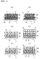
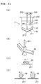
- FIG. 1 shows examples of typical multi-layer electrode structures.
- the electrode structure of FIG. 1(A) is used as the positive electrode of a battery.
- the electrode structure 1 is comprised of an electrode layer 18 consisting of a powdered electrode active substance as an electrode material 11, a powdered electrically-conducting substance 14 and a binder 17 (namely, a bonding agent and a fixer) attached to the surface of the current-collecting member 13.
- the electrode layer 18 is multi-layered in the drawings consisting of a first electrode layer 181 and a second electrode layer 182.
- the first electrode layer 181 has a larger concentration of the powdered electrically-conducting substance 14 and the binder 17 than the second electrode layer 182.
- LiCoO 2 for example, is used as the powdered electrode active substance.
- an ion-conducting polymer 12 is coated on the electrode material 11 of FIG. 1 (A).
- This ion-conducting polymer 12 also functions as a binder, however, a binder 17 is mixed in the first electrode layer 181, to enhance the bonding.
- the first electrode layer 181 has a concentration of powdered electrically-conducting substance 14 larger than that of the second electrode layer 182.
- FIG. 1(C) shows an electrode structure used as the negative electrode of a battery.
- the multi-layered electrode structure 1 is an electrode layer 18 consisting of a powdered electrode active substance as an electrode material 11 and a binder 17 attached to the surface of the current-collecting member 13.
- graphite powder is for example used as the powdered electrode active substance.
- the electrode layer 181 has a larger concentration of the binder 17 than the second electrode layer 182.
- the electrode material of FIG. 1(C) is coated with an ion-conducting polymer 12.
- This ion-conducting polymer 12 also functions as a binder, however, a binder 17 is mixed with the first electrode layer 181 to enhance the bonding.
- FIG. 1(E) shows the electrode structure used as the electrode for a double-layer capacitor.
- the electrode structure 1 is an electrode layer 18 consisting of a large surface area material as an electrode material 11 and a binder 17 attached to the surface of the current-collecting member 13.
- electrically-conducting carbon is used for example as the large surface area material.
- the electrode layer 181 has a larger concentration of binder 17 than the second electrode layer 182.
- the powdered electrically-conducting carbon of FIG. 1(E) is covered by the ion-conducting polymer 12.
- This ion-conducting polymer 12 also functions as a binder, however, a binder 17 is mixed with the first electrode layer 181 to enhance the bonding.
- the electrode material covered with the ion-conducting polymer is described in detail later on.
- the multi-layer electrode is a lamination of a plurality of layers having different characteristics.
- Various methods can be used for obtaining the different characteristics and besides the drawings of FIG. 1(A) through 1(F) can involve changing the types and mixture of allotted substances.
- FIGS. 2(A) and 2(B) are examples of using a powdered electrode active substance as the electrode material 11, and having powdered electrode active substances coated and not coated with ion-conducting polymer 12 as the first electrode layer and the second electrode layer, respectively.
- FIG. 2(C) and 2(D) are examples of using a powdered electrode active substance as the electrode material 11, and having active electrically-conducting carbon coated and not coated with ion-conducting polymer 12 as the first electrode layer and the second electrode layer, respectively.
- binder polymer that easily tends to form fibrils allows bonding the electrode material and powdered electrically-conducting substance with only a small amount of binder.
- binder polymer that easily forms fibrils has poor bonding strength to the current-collecting member so such binder polymer is used in layers other than the first electrode layer.
- the lithium ion density becomes larger and the propagation speed of the lithium ions becomes faster when the electrode layer contains support electrolytic salts.
- the lithium ion movement in the first electrode layer is easily propagated to the second electrode layer.
- a high affinity binder polymer or a polymer having the same electrolyte as in the electrolyte in contact with the electrode layer may be utilized when using the multi-layer electrode structure in a battery or double-layer capacitor.
- the same polymer as the electrolyte can be used in the third electrode layer or a high affinity binder polymer may be used in the third electrode layer placed on the second electrode layer.
- the characteristics of the multi-layer electrode can be changed by various methods including using a binder polymer that bonds securely to the current-collecting member, changing the type of powdered electrically-conducting substance in each layer, changing the average particle size of the powdered electrode active substance, using a binder polymer that conducts ions, and utilizing an ion-conducting polymer which is the same as used for as the electrolyte.
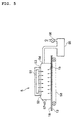
- FIG. 3 An example of the manufacturing method used to produce the multi-layer electrode structure is shown in FIG. 3.
- an electrode material 11 a powdered electrically-conducting substance 14, a binder 17, and a solvent 19 are mixed together in a mixer 3 to obtain a slurry constituting the mixed material 31.
- This mixed material 31 is thinly coated onto the current-collecting member 13.
- the method for coating the mixed material is by a surgical knife applicator, etc. This coating of mixed material is vaporized, dried, and attached to the current-collecting member 13 as the first electrode layer 181.
- the vaporizing and drying of the solvent and coating the mixed material 31 onto the current-collecting member 13 is performed by applying heated air from a heated air oven or by directing infrared radiation from an infrared lamp device.
- a second electrode layer 182 is formed on the first electrode layer 181 in the same manner. Formation of the second layer may be performed before the drying of the first electrode layer.
- the electrode structure comprising the electrode layer 18 coated onto the current-collecting member 13 is moved by a conveyor 63 in a cabinet 62.
- Hot air 65 is blown from a hot air blow outlet 61 toward the electrode layer 18; and the solvent contained in the electrode layer 18 is vaporized.
- the hot air moves the solvent outside via an outlet 64 of the cabinet 62.
- the electrode layer 18 coated onto the current-collecting member 13 is moved by a conveyor 58 in a cabinet 54 and infrared radiation 52 generated by an infrared generator 51 is directed onto the electrode layer 18 coated onto the current-collecting member 13.
- An infrared permeable wall 53 is installed to let the infrared radiation pass between the cabinet 54 and the infrared generator 51. This infrared permeable wall 53 may not be needed if no problem exists with the infrared generator 51 and the type and concentration of vaporized gas. The vaporized solvent 19 from the electrode layer 18 is blocked off from the infrared generator 51 by the infrared permeable wall 53.
- the cabinet 54 filled inside by the solvent 19 reaches an equalized concentration when the concentration attains a high level, such that the vaporization is limited by recovery of the solvent by suctioning it into a solvent recovery unit 55 inside the cabinet 54 with a fan 56.
- external air 57 is supplied into the cabinet 54 so that the external pressure will match the gas pressure inside the cabinet 54.
- this external air 57 is not for vaporizing the solvent 19 by air blow.
- a level of external air 57 to well agitate the uniform concentration of the solvent is sufficient and though dependent on the size of the cabinet 54, a flow speed of for example 0.5 meters per minute is sufficient.
- the infrared radiation may be directed to both sides of the electrode structure.
- Infrared radiation ranging from the near-infrared close to the visible light level to mid-infrared, to far-infrared close to the electromagnetic spectrum can be used, rather than propagation of heat to the mixed material through the air. If the mixed material can be heated remotely with hardly any transmission through air, then any type of infrared radiation may be utilized. Near-infrared radiation has a high transmittance (permeance) rate into the interior of the mixed material so that the interior of the mixed material can be heated.
- FIG. 6 shows an enhanced view of the internal state of the mixed material 31 when the solvent 19 of the mixed material coated on the current-collecting member 13 is vaporized.
- the solvent vaporization process works as follows.
- heated air 65 is applied to the surface of the mixed material 31, the area around the surface of the mixed material 31 suddenly warms up in the heated air, and the solvent around the surface is vigorously vaporized and blown away by the heated air 65.
- the solvent near the surface therefore quickly vaporizes, and to compensate, the solvent at the interior of the mixed material and around the collector electrode moves to the vicinity of the surface.
- the binder and the powdered electrically-conducting substance mixed in the solvent are at this time carried to the surface of the mixed material 31 along with the solvent.
- the concentrations of the binder and the powdered electrically-conducting substance on the current-collecting member side of the mixed material become weak (or low).
- the process for vaporizing the solvent in this invention works as follows.
- the infrared radiation 52 is directed onto the mixed material surface, the infrared radiation 52 permeates into the interior of the mixed material 31, and heats up the entire mixed material. No heated air is blown at this time so that the solvent gradually evaporates (vaporizes) from the surface of the mixed material.
- the concentrations of the binder and the powdered electrically-conducting substance 14 therefore remain uniform overall.
- the binder concentration in the vicinity of the current-collecting member does not become weak (or low) in the electrode layer consisting of dried mixed material 31. Accordingly, the electrode layer adheres well to the current-collecting member 13.
- the concentration of the powdered electrically-conducting substance in the vicinity of the current-collecting member 13 does not become weak either, so that the overall electrical resistance (impedance ohm) of the electrode layer is low. Consequently, the effect of utilizing infrared radiation is especially effective when the overall thickness of the multiple layers is large.
- the current-collecting member 13 may be any material capable of conducting electricity, and the material and shape can be selected according to the electronic component.
- the electrolyte may be aluminum or steel and formed in a plate, leaf or mesh shape. When the current-collecting member is a plate or leaf shape, one or both sides are used according to the structure of the electronic component.
- the electrode layer 18 for adhering to the current-collecting member 13 may be pressed into the current-collecting member to make it further adhere.
- the bonding (adhering) may for instance be performed with a pressing and sealing device 4 such as shown in FIG. 12.
- An electrode structure 1 made from current-collecting member coated with mixed material is enclosed by pressure rollers 41, and the electrode layer can be bonded to the current-collecting member by applying a rotating pressure with a pressure device 43 by means of a backroller 42.
- FIG. 1(A) or FIG. 1(B) can be used as the positive electrode, and a multi-layer electrode structure for a negative electrode can be used as shown in FIG. 1(C) or FIG. 1(D). An electrolyte is positioned between these electrodes.
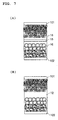
- FIG. 7 shows an example of a battery using as the positive electrode an electrode structure as shown in FIG. 1(B) and as the negative electrode an electrode structure as shown in FIG. 1(D).
- FIG. 7(A) shows the case when the electrolyte is an electrolytic fluid 16, and a separator 15 is placed between the multi-layer electrodes.
- FIG. 7(B) shows the case when the electrolyte is ion-conducting polymer 12 in solid solution.
- the separator 15 is installed to isolate one pair of the multi-layer electrode structures 1, and the electrolyte can be used in solid solution when required according to circumstances.
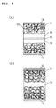
- the dual-layer capacitor has a structure with an electrolyte placed between one pair of multi-layer electrodes of the electrode structure of FIG. 1(E) or one pair of multi-layer electrodes of the electrode structure of FIG. 1(F).
- a double-layer capacitor utilizing the multi-layer electrode structure of FIG. 1(E) is shown in FIG. 8(A)
- a double-layer capacitor utilizing the multi-layer electrode structure of FIG. 1(F) is shown in FIG. 8(B).
- FIG. 8(A) a separator 15 is placed between the multi-layer electrodes when the electrolyte is an electrolytic fluid 16.
- FIG. 8(B) shows the case when the electrolyte is ion-conducting polymer 12 in solid solution.
- the separator 15 is installed to isolate one pair of multi-layer electrode structures 1, and the electrolyte can be used in solid solution when required according to circumstances.
- Drying with heated air was achieved in a heated air oven which applied heated air onto the surface of the mixed material from a hot air blow outlet.
- the heated air was regulated to a temperature of approximately 80 to 200 °C and a flow speed of 15 to 25 meters per minute.
- a far-infrared ceramic panel heater PH-100, iPH100C (made by SAKAGUCHI E.H VOC CORP.) was utilized as the infrared lamp device.
- the infrared radiation drying conditions for all the samples were 30 volts for one hour.
- Sample 1 is an electrode for useful capacitors.
- a first electrode layer was formed by adding phenol active carbon made from phenol resins (made by Kansai Chemical Corp.) with carbon black as the powdered electrically-conducting substance, and dry type mixing utilizing a mixer.
- polymer A1 was added to the dry mix as the binder and mixing performed. Further, NMP N-methyl-2-pyrrolidone was added as the solvent and mixing performed. After the mixing, the material was coated onto the current-collector member with a surgical knife applicator. The samples were then dried either by heating with infrared radiation or by heated air.
- the thickness of the electrode was 75 ⁇ m.
- a second electrode layer was formed using the same method as was used to form the first electrode layer, except that the amount of polymer A1 was reduced and the amount of dilute solvent increased.
- the thickness of the electrode was 250 ⁇ m.
- the first electrode layer of sample 2 was made by approximately the same method as used to form the electrode layers of sample 1.
- the second electrode layer of sample 2 was prepared by adding Teflon added to the polymer A1 used as the binder. Teflon used was a polymer that forms easily into fibrils.
- Sample 3 is useful as a capacitor electrode and manufactured in approximately the same way as sample 1 and sample 2.
- the multi-layer electrode of sample 3 did not include the carbon black additive in either the first electrode layer or second electrode layer.
- Polymer A1 was added as a binder to the first electrode and Teflon was added to the second electrode.
- the polymer A1 is an ion-conducting polymer material and is shown in Table 3.
- Sample 4 is an electrode structure for a positive electrode of a battery.
- LiCoO 2 was the electrode material, and carbon black served as the powdered electrically-conducting substance.
- polymer A1 was added as the binder, and in the second electrode, PVDF was added as the binder.
- PVDF polyvinylidene fluoride
- NMP N methylpyrrolidone
- MEK methylethylketone
- Comparison 1 in Table 1 is an example of a thickened second electrode layer without the first electrode layer of the sample 2.
- Comparison 2 in Table 1 is a thickened second electrode layer without the first electrode layer of the sample 4.
- Comparison 1, as shown in Table 2, shows a lower peeling strength and a higher impedance (ohm) either with infrared heating or heated air comparing to the sample 2.
- Comparison 2 shows, as shown in Table 2, a lower peeling strength and a higher impedance (ohm) either with infrared heating or heated air comparing to the sample 4. Accordingly, the multi-layer electrode structure shows more effective peeling strength and impedance (ohm) than a single electrode layer.
- cellophane tape was attached to the electrode layer fabricated on the surface of the current-collecting member, and the cellophane tape then pulled away to make the electrode layer stuck to the cellophane tape separate from the current-collecting member.
- FIG. 9 shows the electrode layer stuck to the cellophane tape (view using photograph).
- FIG. 9(A) a mere fraction of the upper layer of the electrode layer has thinly peeled away (The black portion is the portion where the electrode layer has peeled.) and is rank a .
- a middle layer of the electrode layer has thinly peeled off (The black portion is the portion where the electrode layer has peeled.) and is rank b .
- the electrode layer has completely peeled off from the current-collecting member (The black portion is the portion where the electrode layer has peeled.) and is rank c .
- the electrodes formed on the collector element were enclosed by copper plates of 2 centimeters in diameter and 5 millimeters thick. A pressure of 4.5 kilograms per centimeter was applied from above and below, and the resistance at 10 kilohertz AC was measured with an impedance analyzer.
- the peeling strength for the infrared heated samples was found to be "a" rank and for the hot air heated samples was found to be "b” rank.
- the peeling strength for infrared heated samples was found to be one rank higher.
- the impedance test results also indicated that the impedance (ohm) of the infrared heated samples was small, and especially lowered for sample 2.
- the electrode material coated with ion-conducting polymer is described next.
- the powdered electrode active substance 11 has the shape of particles consisting of bonded particles like LiCoO 2 , and the process for depositing the ion-conducting polymer 12 is shown.
- the term "coating” refers to a state where ions can migrate sufficiently between the ion-conducting polymer 12 and the powdered electrode active substance 11 over their entire surfaces.
- the ion-conducting polymer 12 is deposited on the surface of the powdered electrode active substance 11 as a coating of ion-conducting polymer 12. The finer the particles, the more active the powdered electrode active substance 11 becomes.
- the powder shape such as for the powdered electrode active substance 11 and powdered conducting material 14 is a fine particle substance. Further such a powder is a collection of many substances. In certain cases, this fine particle substance refers to a state wherein a large number of substances in a fine particle state constitute an agglomeration.
- the powdered electrode active substance uses ion intercalate-deintercalate materials and ⁇ -conjugated conductive macromolecular materials.
- the electrode active substance used as the positive electrode for non-aqueous electrolyte batteries There are no particular restrictions on the electrode active substance used as the positive electrode for non-aqueous electrolyte batteries. However, in the case of chargeable batteries, chalcogen compounds allowing ion intercalate-deintercalate or composite chalcogen compounds containing lithium are recommended.
- Useful chalcogen compounds may be FeS 2 , TiS 2 , MoS 2 , V 2 O 5 , V 6 O 13 , MnO 2 , etc.
- Typical chalcogen compounds containing lithium are LiCoO 2 , Li x Ni y M 1-y O 2 , where M expresses one or more metallic elements selected from transitional metals and aluminum, and preferably one or more metallic elements selected from among cobalt, manganese, titanium, chromium, vanadium, aluminum, and 0.05 ⁇ x ⁇ 1.10, 0.5 ⁇ y ⁇ 1.0) and composite lithium oxides, LiNiO 2 , LiMnO 2 , LiMn 2 O 4 , etc.
- These compounds may be obtained by using lithium, cobalt, nickel, manganese oxides, salts or hydroxides as starting materials, mixing these starting materials together according to composition desired and baking the mixture in an oxygen atmosphere at a temperature of 600 to 1000 °C.
- the electrode active material used as the negative electrode for non-aqueous electrolyte batteries there are no particular restrictions on the electrode active material used as the negative electrode for non-aqueous electrolyte batteries. However, a material allowing lithium ion insertion/separation may be used, as well as lithium metal, lithium alloys (alloys such as lithium and aluminum, lead, indium) and carbon quality materials may be utilized.
- Polyacetylene types polyaniline types, polypyrrole types, polythiophene types, poly p(para)-phenylene types, polycarbazole types, polyacene types and sulfur polymer types are among the useful ⁇ -conjugated conductive macromolecular materials.
- lithium metals in the negative electrode achieves a large battery capacity particularly in primary non-aqueous electrolyte batteries.
- carbon materials in the negative electrodes that are capable of lithium ion insertion/separation yields a longer battery cycle life span.
- carbon material used but materials such as pyrolytic carbon types, coke types (pitch coke, needle coke and petroleum coke, etc.) graphite types, glass carbon types, organic macromolecular compound fired products (carbonized pieces baked to a suitable temperature such as phenol resin, furan resin) carbon fibers and active carbon may be utilized.
- the powdered electrically-conducting substance raises the conductivity of the electrode structure and though there are no particular restrictions, materials such as metal powder and carbon powder may be used.
- Particularly preferred carbon powders are pyrolytic carbons such as carbon black, and their graphite products, artificial and natural scaly graphite powder, carbon fibers and their graphite products, etc. Product mixtures of these carbon powders can also be utilized.
- the ion-conducting polymer is a polymer which can dissolve at least the lithium salts described hereafter at a concentration of at least 0.1 M (moles/l), the polymer containing the lithium salt at a concentration of at least 0.1 M having an electrical conductivity of 10 -8 S (siemens)/cm at room temperature.
- the ion-conducting polymer dissolves at least lithium salts to a concentration of 0.8 M-1.5 M, the resulting polymer solution having an electrical conductivity of 10 -3 S/cm to 10 -5 S/cm at room temperature.
- the lithium salt is at least one type of lithium salt having ClO 4 - , CF 3 SO 3 - , BF 4 - , PF 6 - , AsF 6 - , SbF 6 - , CF 3 CO 2 - or (CF 3 SO 2 ) 2 N - as an anion.
- the ion-conducting polymer raw material is a substance which produces the ion-conducting polymer by cross-linking, etc., when energy is supplied externally.
- the energy may be heat, ultraviolet light, light or electron radiation.
- the method of coating the powdered conductive material with the ion-conducting polymer as is shown in general in FIG. 10 is to press-slide the ion-conducting polymer and the powdered electrode active substance against each other.
- the particle surfaces of the powdered electrode active substance are coated with the ion-conducting polymer, no voids are formed, and gaps in the powdered substance are reduced.
- Press-sliding is the action of sliding while pressing mixtures 10 of the ion-conducting polymer 12 or the raw material of the ion-conducting polymer 12 and the powdered substance 11 together. An external force is applied to the mixtures so that they cohere to each other and the particles rotate, and this process is performed repeatedly to obtain a press-sliding product.
- the press-sliding mixer 2 is shown, for example, in FIG. 11.
- the mixture 10 of the ion-conducting polymer 12 or its raw material with the powdered substance 11, or the mixture 10 comprising this mixture and a solvent or the like, is introduced into a container 21 via top 212, and a main blade 22 is rotated. There is a gap between a base or bottom 211 of the container 21 and a bottom surface of the main blade 22.
- part of the mixture 10 enters the space between the base 211 of the container and the main blade 22, and is subjected to press-sliding, and is kneaded. This process is repeated so that the ion-conducting polymer 12 or its raw material coats the powdered substance 11.
- a press-sliding mixer 2 may if necessary be provided with a dispersion blade 23 in the container 21.
- the dispersion blade 23 is rotated at high speed to disperse the press-slid mixture 10.
- the container 21 is provided for holding the mixture 10 which is press-slid and stirred.
- the bottom surface or base 211 of the container 21 slants upwards from the central bottom part 2111 towards the circumference of container 21.
- the bottom 211 may be formed in the shape of, for example, a grinding mortar, and the angle of the slant of bottom part 211 may, for example, be 120°.
- the bottom 211 of the container is wear-resistant, and can be formed by thermal spraying with tungsten or carbide using SUS. A plurality of bottom parts of this type may also be formed on the bottom surface 211.
- the main blade 22 functions together with the bottom surface 211 of the container 21, serving to press-slide and stir the mixture 10.
- the main blade 22 is positioned via a shaft 221 to the desired location relative to the bottom 211 of the container 21 as shown for example in FIGS. 11(A) and 11(B). Main blade 22 curves upwards corresponding to the slant of the bottom 211 of the container 21.
- the main blade 22 may comprise two blades attached from the center part as shown in FIG. 11(B), or it may comprise a larger number of blades, e.g. 10 or more, depending on the amount and type of mixture.
- the number of rotations of a main motor 222 driving the main shaft 221 is set low for example to 120 rpm or less, when press-sliding is performed.
- the gap between the bottom surface 211 of the container 21 and the base surface of the main blade 22 is set as narrow as is necessary for press-sliding the mixture, for example 15 mm or less. This distance depends on the capacity of the press-sliding mixer 2 and on the shape of the main blade, etc.
- the surface in the motion direction (press-sliding direction) of the main blade 22 is formed so that a pressing angle ⁇ relative to the bottom surface 211 of the container 21 is an acute angle.
- a pressing angle ⁇ relative to the bottom surface 211 of the container 21 is an acute angle.
- the cross-section of the main blade 22 is a reverse trapezoid as shown in FIG. 11(C)
- the pressing angle is from 3° to 70°.
- the cross-section of the main blade 22 may also be circular or have a rounded corner as shown in FIG. 11(D).
- the material of the main blade has wear-resistant properties, and is formed for example by thermal spraying with tungsten or carbide using SUS.
- the mixture 10 can be collected around the main shaft 221 by rotating the main shaft 221 in the reverse direction.
- the center parts of the main blade 22 are also disposed in positions of the bottom part corresponding to their number.
- the dispersion blade 23 is intended to disperse the mixture 10 which has been press-slid by the main blade 22.
- the dispersion blade 23 is disposed in a position at which the mixture 10 can be dispersed, and it rotates via motor 231 at a high speed such as 1000 to 4000 min -1 . Due to this high speed rotation, the ion-conducting polymer 12 or its raw material coated on the particle surfaces of the powdered substance 11 uniformly disperses through the whole of the powdered substance.
- a multi-layer electrode structure that adheres well to the current-collecting member can be obtained.
- a multi-layer electrode structure with low electrical resistance can be obtained.
- a multi-layer battery or double-layer capacitor having low electrical resistance and good bonding can be obtained.
Abstract
Description
- The present invention relates to a multi-layer electrode structure, a method for manufacturing same and a battery and an electrical double-layer capacitor utilizing the multi-layer electrode structure.
- A typical electrode structure of the prior art is manufactured by coating a current-collecting member surface with a compound mixture containing an electrode material, a powdered electrically-conducting substance, a binder and solvent, and vaporizing off the solvent to form a layered electrode structure.
- This invention has the object of manufacturing an electrode structure comprised of multiple electrode layers.
- This invention has the further object of providing a multi-layer electrode structure having effective adhesive properties.
- This invention has the yet further object of providing a multi-layer electrode structure with low electrical resistance.
- This invention has the still further object of providing a battery and double-layer capacitor comprised of a multi-layer electrode structure with low electrical resistance and effective adhesive properties.
- This invention is directed to a multi-layer electrode structure comprised of a plurality of electrode layers at least composed of a binder made of a macromolecular substance and an electrode material coated on a current-collecting member and wherein the first electrode layer formed in contact with the current-collecting member and a second electrode layer formed on the first electrode layer are formed of different constituents and/or have different proportions of the same constituent.
- This invention is further directed to a multi-layer electrode structure comprised of a plurality of electrode layers at least composed of a binder made of a macromolecular substance and an electrode material, coated on a current-collecting member and wherein the binder of the first electrode layer formed in contact with the current-collecting member has a stronger adhesive strength than that of the second electrode layer formed on the first electrode layer.
- This invention is still further directed to a multi-layer electrode structure comprised of a plurality of electrode layers at least composed of a binder made of a macromolecular substance, an electrode material and a powdered electrically-conducting substance coated on a current-collecting member, wherein each layer at least includes a macromolecular substance and wherein the first electrode layer formed in contact with a current-collecting member, has a higher electrical conduction rate than that of the second electrode layer formed on the first electrode layer.
- This invention is still further directed to a multi-layer electrode structure as above, wherein at least one layer of electrode material is adhered by an ion-conducting polymer.
- This invention is still further directed to a multi-layer electrode structure as above, wherein the macromolecular binder for one electrode layer other than the first electrode layer uses a binder polymer easily prone to form fibrils.
- This invention is still further directed to a battery containing at least one electrode at least comprised of a multi-layer electrode structure coated on a current-colleting layer, each layer composed of a binder made of a macromolecular substance, an electrode material, and a powdered electrically-conducting substance wherein the battery further includes a liquid or non-liquid electrolyte between the electrodes, wherein the first electrode layer formed in contact with a current-collecting member has a binder of stronger adhesive strength and a higher electrical conduction rate than the second electrode layer formed on the first electrode layer.
- This invention is still further directed to a battery as above, wherein a binder of the same liquid or non-liquid electrolyte or of a high affinity is utilized in the electrode layer in contact with the liquid or non-liquid electrolyte.
- This invention is still further directed to a double-layer capacitor with at least one electrode comprised of a multi-layer electrode structure coated on a current-collecting member, each layer at least composed of a binder, an electrode material, and a powdered electrically-conducting substance, wherein the double-layer capacitor further includes a liquid or non-liquid electrolyte between the electrodes, wherein the first electrode layer formed in contact with the current-collecting member has a binder of a stronger adhesive strength and a higher electrical conduction rate than the second electrode layer formed on the first electrode layer.
- This invention is still further directed to a double-layer capacitor as above, wherein a binder of the same liquid or non-liquid electrolyte or of a high affinity is utilized in the electrode layer in contact with the electrolyte.
- This invention is further directed to a method for manufacturing a multi-layer electrode structure as above described, the method comprising the steps of forming a first electrode layer by coating a mixed material containing a macromolecular binder, an electrode substance, and a solvent onto a current-collecting member and drying the mixed material, forming a second electrode layer by coating a mixed material containing a macromolecular binder, an electrode substance, and a solvent on top of the first electrode layer and drying the mixed material to form an electrode of multiple layers, and wherein the macromolecular binders used are such that the binding strength of the first electrode layer is stronger than that of the second electrode layer.
- This invention is further directed to a method of manufacturing a multi-layer electrode structure as previously described, the method comprising the steps of forming a first electrode layer by coating a mixed material containing a macromolecular binder, an electrode substance, a solvent, and a powdered electrically-conducting substance onto a current-collecting member and drying the mixed material, forming a second electrode layer by coating a mixed material containing a macromolecular binder, an electrode substance, a solvent, and a powdered electrically-conducting substance on top of the first electrode layer and drying the mixed material to form an electrode of multiple layers, and using powdered electrically-conducting substances such that the electrical conduction rate of the first electrode layer is higher than that of the second electrode layer.
- This invention is still further directed to a manufacturing method for a multi-layer electrode structure as above, wherein a mixed material containing a macromolecular binder, an electrode substance, and a solvent are mixed and coated onto the second electrode layer and subjected to drying the mixed material to form an electrode layer such that the third electrode layer has a stronger bonding force than the second electrode layer.
- This invention is still further directed to a multi-layer electrode structure as above, wherein the electrode material for at least one electrode layer is coated with an ion-conducting polymer.
- This invention is further directed to a multi-layer electrode structure as above, wherein the macromolecular binder for at least one electrode layer other than the first electrode layer uses a binder polymer easily prone to form fibrils.
- This invention is still further directed to a multi-layer electrode structure as above, wherein the powdered electrically-conducting substance of the first electrode layer contains support electrolytic salts.
- This invention is still further directed to a method of manufacturing a battery with at least one electrode comprised of a multi-layer electrode structure as above described, the method comprising forming a first electrode layer by coating a mixed material containing a macromolecular binder, an electrode substance, a solvent, and a powdered electrically-conducting substance onto a current-collecting member and drying the mixed material, forming a second electrode layer by coating a mixed material containing a macromolecular binder, an electrode substance, a solvent, and a powdered electrically-conducting substance on top of the first electrode layer and drying the mixed material to form an electrode of multiple layers, and using macromolecular binders such that the bonding force of the first electrode layer is stronger than the bonding force of the second electrode layer and using powdered electrically-conducting substances so that the electrical conduction rate of the first electrode layer is higher than the second electrode layer.
- This invention is yet further directed to a method of manufacturing a double-layer capacitor with an electrode comprised of a multi-layer electrode structure as above described, the method comprising forming a first electrode layer by coating a mixed material containing a macromolecular binder, an electrode substance, a solvent, and a powdered electrically-conducting substance onto a current-collecting member and drying the mixed material, forming a second electrode layer by coating a mixed material containing a macromolecular binder, an electrode substance, a solvent, and a powdered electrically-conducting substance on top of the first electrode layer and drying the mixed material to form an electrode of multiple layers, and using macromolecular binders such that the bonding force of the first electrode layer is stronger than the binding force of the second electrode layer and using powdered electrically-conducting substances such that the electrical conduction rate of the first electrode layer is higher than that of the second electrode layer.
- The above and other objects and the attendant advantages of the present invention will become readily apparent by reference to the following detailed description when considered in conjunction with the accompanying drawings.
-
- FIGS. 1(A)-1(F)
- are views of different types of multi-layer electrode structures.
- FIGS. 2(A)-2(D)
- are views of other multi-layer electrode structures.
- FIG. 3
- is a schematic view of the fabrication of the electrode structure.
- FIG. 4
- is a schematic view of a prior art coating method using a heated air oven.
- FIG. 5
- is a schematic view of the coating method of this invention using an infrared ray lamp device.
- FIGS. 6(A) and 6(B)
- illustrate the drying of the mixed compound by heated air and by infrared radiation, respectively.
- FIGS. 7(A) and 7(B)
- illustrate alternative battery structures of this invention.
- FIGS. 8(A) and 8(B)
- illustrate alternative structures for the electrical double-layer capacitor.
- FIGS. 9(A)-9(C)
- show (taken from photographs) the level of peeling strength as tested.
- FIG. 10
- is a schematic view showing the coating of ion-conducting polymer.
- FIGS. 11(A)-11(D)
- illustrate a press-sliding mixer.
- FIG. 12
- is a plan view showing a pressing and sealing device.
- The embodiments of the invention are next described while referring to the accompanying drawings.
- The multi-layer electrode structure of this invention can be used as at least one electrode of electronic components having an electrolyte between the electrodes. When the electrical component is a battery, the multi-layer electrode structure is capable of exchanging electricity by way of the electrolyte ions. When the electrical component is a double-layer capacitor, the multi-layer electrode structure forms an electrical double-layer capacitor between the electrolyte and material with a large surface area.
- FIG. 1 shows examples of typical multi-layer electrode structures. The electrode structure of FIG. 1(A) is used as the positive electrode of a battery. In this figure, the
electrode structure 1 is comprised of anelectrode layer 18 consisting of a powdered electrode active substance as anelectrode material 11, a powdered electrically-conductingsubstance 14 and a binder 17 (namely, a bonding agent and a fixer) attached to the surface of the current-collectingmember 13. - The
electrode layer 18 is multi-layered in the drawings consisting of afirst electrode layer 181 and asecond electrode layer 182. Thefirst electrode layer 181 has a larger concentration of the powdered electrically-conductingsubstance 14 and thebinder 17 than thesecond electrode layer 182. Here, LiCoO2 for example, is used as the powdered electrode active substance. - In FIG. 1(B), an ion-conducting
polymer 12 is coated on theelectrode material 11 of FIG. 1 (A). This ion-conductingpolymer 12 also functions as a binder, however, abinder 17 is mixed in thefirst electrode layer 181, to enhance the bonding. Thefirst electrode layer 181 has a concentration of powdered electrically-conductingsubstance 14 larger than that of thesecond electrode layer 182. - FIG. 1(C) shows an electrode structure used as the negative electrode of a battery. In this figure, the
multi-layered electrode structure 1 is anelectrode layer 18 consisting of a powdered electrode active substance as anelectrode material 11 and abinder 17 attached to the surface of the current-collectingmember 13. Here, graphite powder is for example used as the powdered electrode active substance. Theelectrode layer 181 has a larger concentration of thebinder 17 than thesecond electrode layer 182. - In FIG. 1(D), the electrode material of FIG. 1(C) is coated with an ion-conducting
polymer 12. This ion-conductingpolymer 12 also functions as a binder, however, abinder 17 is mixed with thefirst electrode layer 181 to enhance the bonding. - FIG. 1(E) shows the electrode structure used as the electrode for a double-layer capacitor. In this figure, the
electrode structure 1 is anelectrode layer 18 consisting of a large surface area material as anelectrode material 11 and abinder 17 attached to the surface of the current-collectingmember 13. Here, electrically-conducting carbon is used for example as the large surface area material. Theelectrode layer 181 has a larger concentration ofbinder 17 than thesecond electrode layer 182. - In FIG. 1(F), the powdered electrically-conducting carbon of FIG. 1(E) is covered by the ion-conducting
polymer 12. This ion-conductingpolymer 12 also functions as a binder, however, abinder 17 is mixed with thefirst electrode layer 181 to enhance the bonding. The electrode material covered with the ion-conducting polymer is described in detail later on. - The multi-layer electrode is a lamination of a plurality of layers having different characteristics. Various methods can be used for obtaining the different characteristics and besides the drawings of FIG. 1(A) through 1(F) can involve changing the types and mixture of allotted substances.
- FIGS. 2(A) and 2(B) are examples of using a powdered electrode active substance as the
electrode material 11, and having powdered electrode active substances coated and not coated with ion-conductingpolymer 12 as the first electrode layer and the second electrode layer, respectively. FIG. 2(C) and 2(D) are examples of using a powdered electrode active substance as theelectrode material 11, and having active electrically-conducting carbon coated and not coated with ion-conductingpolymer 12 as the first electrode layer and the second electrode layer, respectively. - Using a binder polymer that easily tends to form fibrils as the binder in the second electrode layer allows bonding the electrode material and powdered electrically-conducting substance with only a small amount of binder. However, binder polymer that easily forms fibrils has poor bonding strength to the current-collecting member so such binder polymer is used in layers other than the first electrode layer.
- Further, the lithium ion density becomes larger and the propagation speed of the lithium ions becomes faster when the electrode layer contains support electrolytic salts. In particular, when support electrolytic salts are inserted into the first electrode layer, the lithium ion movement in the first electrode layer is easily propagated to the second electrode layer.
- A high affinity binder polymer or a polymer having the same electrolyte as in the electrolyte in contact with the electrode layer may be utilized when using the multi-layer electrode structure in a battery or double-layer capacitor. For example, the same polymer as the electrolyte can be used in the third electrode layer or a high affinity binder polymer may be used in the third electrode layer placed on the second electrode layer.
- Further, the characteristics of the multi-layer electrode can be changed by various methods including using a binder polymer that bonds securely to the current-collecting member, changing the type of powdered electrically-conducting substance in each layer, changing the average particle size of the powdered electrode active substance, using a binder polymer that conducts ions, and utilizing an ion-conducting polymer which is the same as used for as the electrolyte.
- An example of the manufacturing method used to produce the multi-layer electrode structure is shown in FIG. 3. To manufacture the
multi-layer electrode structure 1, anelectrode material 11, a powdered electrically-conductingsubstance 14, abinder 17, and a solvent 19 are mixed together in amixer 3 to obtain a slurry constituting themixed material 31. - This
mixed material 31 is thinly coated onto the current-collectingmember 13. The method for coating the mixed material is by a surgical knife applicator, etc. This coating of mixed material is vaporized, dried, and attached to the current-collectingmember 13 as thefirst electrode layer 181. - Here, the vaporizing and drying of the solvent and coating the
mixed material 31 onto the current-collectingmember 13 is performed by applying heated air from a heated air oven or by directing infrared radiation from an infrared lamp device. Next, asecond electrode layer 182 is formed on thefirst electrode layer 181 in the same manner. Formation of the second layer may be performed before the drying of the first electrode layer. - As shown, for example, in FIG. 4, with respect to a hot air heating device 6, the electrode structure comprising the
electrode layer 18 coated onto the current-collectingmember 13 is moved by aconveyor 63 in acabinet 62.Hot air 65 is blown from a hotair blow outlet 61 toward theelectrode layer 18; and the solvent contained in theelectrode layer 18 is vaporized. The hot air moves the solvent outside via anoutlet 64 of thecabinet 62. - As shown for example in FIG. 5, with respect to an
infrared lamp device 5, theelectrode layer 18 coated onto the current-collectingmember 13 is moved by aconveyor 58 in acabinet 54 andinfrared radiation 52 generated by aninfrared generator 51 is directed onto theelectrode layer 18 coated onto the current-collectingmember 13. - An infrared
permeable wall 53 is installed to let the infrared radiation pass between thecabinet 54 and theinfrared generator 51. This infraredpermeable wall 53 may not be needed if no problem exists with theinfrared generator 51 and the type and concentration of vaporized gas. The vaporized solvent 19 from theelectrode layer 18 is blocked off from theinfrared generator 51 by the infraredpermeable wall 53. - The
cabinet 54 filled inside by the solvent 19 reaches an equalized concentration when the concentration attains a high level, such that the vaporization is limited by recovery of the solvent by suctioning it into asolvent recovery unit 55 inside thecabinet 54 with afan 56. In that time,external air 57 is supplied into thecabinet 54 so that the external pressure will match the gas pressure inside thecabinet 54. However, thisexternal air 57 is not for vaporizing the solvent 19 by air blow. - A level of
external air 57 to well agitate the uniform concentration of the solvent is sufficient and though dependent on the size of thecabinet 54, a flow speed of for example 0.5 meters per minute is sufficient. When theelectrode layer 18 is coated on both surfaces of the current-collectingmember 13, the infrared radiation may be directed to both sides of the electrode structure. - Infrared radiation ranging from the near-infrared close to the visible light level to mid-infrared, to far-infrared close to the electromagnetic spectrum can be used, rather than propagation of heat to the mixed material through the air. If the mixed material can be heated remotely with hardly any transmission through air, then any type of infrared radiation may be utilized. Near-infrared radiation has a high transmittance (permeance) rate into the interior of the mixed material so that the interior of the mixed material can be heated.
- When infrared radiation is used as a means to vaporize the solvent 19 and dry the
mixed material 31, theelectrode layer 18 adheres (or bonds) well to the current-collectingmember 13, and the electrical resistance of theelectrode layer 18 is also low. FIG. 6 shows an enhanced view of the internal state of themixed material 31 when the solvent 19 of the mixed material coated on the current-collectingmember 13 is vaporized. - In FIG. 6(A), the solvent vaporization process works as follows. When
heated air 65 is applied to the surface of themixed material 31, the area around the surface of themixed material 31 suddenly warms up in the heated air, and the solvent around the surface is vigorously vaporized and blown away by theheated air 65. - The solvent near the surface therefore quickly vaporizes, and to compensate, the solvent at the interior of the mixed material and around the collector electrode moves to the vicinity of the surface.
- The binder and the powdered electrically-conducting substance mixed in the solvent are at this time carried to the surface of the
mixed material 31 along with the solvent. As a result, the concentrations of the binder and the powdered electrically-conducting substance on the current-collecting member side of the mixed material become weak (or low). - In contrast, the process for vaporizing the solvent in this invention as shown in FIG. 6(B), works as follows. When the
infrared radiation 52 is directed onto the mixed material surface, theinfrared radiation 52 permeates into the interior of themixed material 31, and heats up the entire mixed material. No heated air is blown at this time so that the solvent gradually evaporates (vaporizes) from the surface of the mixed material. - The concentrations of the binder and the powdered electrically-conducting
substance 14 therefore remain uniform overall. As a result, the binder concentration in the vicinity of the current-collecting member does not become weak (or low) in the electrode layer consisting of driedmixed material 31. Accordingly, the electrode layer adheres well to the current-collectingmember 13. - Further, the concentration of the powdered electrically-conducting substance in the vicinity of the current-collecting
member 13 does not become weak either, so that the overall electrical resistance (impedance ohm) of the electrode layer is low. Consequently, the effect of utilizing infrared radiation is especially effective when the overall thickness of the multiple layers is large. - The current-collecting
member 13 may be any material capable of conducting electricity, and the material and shape can be selected according to the electronic component. As one example, the electrolyte may be aluminum or steel and formed in a plate, leaf or mesh shape. When the current-collecting member is a plate or leaf shape, one or both sides are used according to the structure of the electronic component. - The
electrode layer 18 for adhering to the current-collectingmember 13 may be pressed into the current-collecting member to make it further adhere. The bonding (adhering) may for instance be performed with a pressing and sealing device 4 such as shown in FIG. 12. - An
electrode structure 1 made from current-collecting member coated with mixed material is enclosed bypressure rollers 41, and the electrode layer can be bonded to the current-collecting member by applying a rotating pressure with apressure device 43 by means of abackroller 42. - The multi-layer electrode structure of FIG. 1(A) or FIG. 1(B) can be used as the positive electrode, and a multi-layer electrode structure for a negative electrode can be used as shown in FIG. 1(C) or FIG. 1(D). An electrolyte is positioned between these electrodes. FIG. 7 shows an example of a battery using as the positive electrode an electrode structure as shown in FIG. 1(B) and as the negative electrode an electrode structure as shown in FIG. 1(D).
- Here, FIG. 7(A) shows the case when the electrolyte is an
electrolytic fluid 16, and aseparator 15 is placed between the multi-layer electrodes. FIG. 7(B) shows the case when the electrolyte is ion-conductingpolymer 12 in solid solution. Theseparator 15 is installed to isolate one pair of themulti-layer electrode structures 1, and the electrolyte can be used in solid solution when required according to circumstances. - The dual-layer capacitor has a structure with an electrolyte placed between one pair of multi-layer electrodes of the electrode structure of FIG. 1(E) or one pair of multi-layer electrodes of the electrode structure of FIG. 1(F). A double-layer capacitor utilizing the multi-layer electrode structure of FIG. 1(E) is shown in FIG. 8(A), and a double-layer capacitor utilizing the multi-layer electrode structure of FIG. 1(F) is shown in FIG. 8(B).
- In FIG. 8(A), a
separator 15 is placed between the multi-layer electrodes when the electrolyte is anelectrolytic fluid 16. FIG. 8(B) shows the case when the electrolyte is ion-conductingpolymer 12 in solid solution. Theseparator 15 is installed to isolate one pair ofmulti-layer electrode structures 1, and the electrolyte can be used in solid solution when required according to circumstances. - Examples of the multi-layer electrode structure are described next.
- Four multi-layer electrode structure sample pieces 1 - 4 were prepared and dried using two types of heating methods; one method was infrared heating and the other was with heated air. The peeling strength and impedance (ohm) of each of these sample pieces were measured. The ratio (proportions) of electrode material, powdered conducting material, binder, and solvent material used in the manufacture of the sample pieces are shown in Table 1. The results of testing peeling strength and impedance (ohm) are shown in Table 2.

INFRARED HEATING HOT AIR HEATING Dry Strength Peeling Strength Impedance (ohm) Peeling Strength Impedance (ohm) Sample 130V, 1h a 0.1 b 0.5 Sample 230V, 1h a 0.15 b 0.7 Sample 330V, 1h a 0.7 b 6 Sample 4 30V, 1h a 0.9 b 2.3 Comparison 130V, 1h b 0.2 c 1.2 Comparison 230V, lh b 2 c 6 - Drying with heated air was achieved in a heated air oven which applied heated air onto the surface of the mixed material from a hot air blow outlet. The heated air was regulated to a temperature of approximately 80 to 200 °C and a flow speed of 15 to 25 meters per minute.
- A far-infrared ceramic panel heater PH-100, iPH100C (made by SAKAGUCHI E.H VOC CORP.) was utilized as the infrared lamp device. The infrared radiation drying conditions for all the samples were 30 volts for one hour.
-
Sample 1 is an electrode for useful capacitors. A first electrode layer was formed by adding phenol active carbon made from phenol resins (made by Kansai Chemical Corp.) with carbon black as the powdered electrically-conducting substance, and dry type mixing utilizing a mixer. - Afterwards, polymer A1 was added to the dry mix as the binder and mixing performed. Further, NMP N-methyl-2-pyrrolidone was added as the solvent and mixing performed. After the mixing, the material was coated onto the current-collector member with a surgical knife applicator. The samples were then dried either by heating with infrared radiation or by heated air.
- The thickness of the electrode was 75 µm. A second electrode layer was formed using the same method as was used to form the first electrode layer, except that the amount of polymer A1 was reduced and the amount of dilute solvent increased. The thickness of the electrode was 250 µm.
- The first electrode layer of
sample 2 was made by approximately the same method as used to form the electrode layers ofsample 1. The second electrode layer ofsample 2 was prepared by adding Teflon added to the polymer A1 used as the binder. Teflon used was a polymer that forms easily into fibrils. -
Sample 3 is useful as a capacitor electrode and manufactured in approximately the same way assample 1 andsample 2. The multi-layer electrode ofsample 3 did not include the carbon black additive in either the first electrode layer or second electrode layer. Polymer A1 was added as a binder to the first electrode and Teflon was added to the second electrode. The polymer A1 is an ion-conducting polymer material and is shown in Table 3. - Sample 4 is an electrode structure for a positive electrode of a battery. In sample 4, LiCoO2 was the electrode material, and carbon black served as the powdered electrically-conducting substance. In the first electrode, polymer A1 was added as the binder, and in the second electrode, PVDF was added as the binder.
- PVDF (polyvinylidene fluoride) is a polymer that forms easily into fibrils. NMP (N methylpyrrolidone) was used as the solvent in the first electrode layer, and MEK (methylethylketone) was used as the solvent in the second electrode layer.
Ion-conducting polymer raw material (A1) Substance Mixing ratio (weight parts) Difunctional (propylene glycol/ethylene glycol) random copolymer, SANNIX FA-103 (PO/EO=2/8, Mw=3,282, Sanyo Chemical Industries, Ltd.) 8.36 Difunctional polyol, 1, 4-butanediol 0.34 Ethylene cyanohydrins 1.27 Reaction catalyst NC-IM (Sankyo Air Products K.K.) 0.03 Total 10 -
Comparison 1 in Table 1 is an example of a thickened second electrode layer without the first electrode layer of thesample 2.Comparison 2 in Table 1 is a thickened second electrode layer without the first electrode layer of the sample 4.Comparison 1, as shown in Table 2, shows a lower peeling strength and a higher impedance (ohm) either with infrared heating or heated air comparing to thesample 2. - Also,
Comparison 2 shows, as shown in Table 2, a lower peeling strength and a higher impedance (ohm) either with infrared heating or heated air comparing to the sample 4. Accordingly, the multi-layer electrode structure shows more effective peeling strength and impedance (ohm) than a single electrode layer. - To measure the peeling strength, cellophane tape was attached to the electrode layer fabricated on the surface of the current-collecting member, and the cellophane tape then pulled away to make the electrode layer stuck to the cellophane tape separate from the current-collecting member.
- A peeling strength ranking could then be established according to the amount of electrode layer peeled from the surface of the current-collecting member. FIG. 9 shows the electrode layer stuck to the cellophane tape (view using photograph).
- In FIG. 9(A), a mere fraction of the upper layer of the electrode layer has thinly peeled away (The black portion is the portion where the electrode layer has peeled.) and is rank a.
- In FIG. 9(B), a middle layer of the electrode layer has thinly peeled off (The black portion is the portion where the electrode layer has peeled.) and is rank b.
- In FIG. 9(C) the electrode layer has completely peeled off from the current-collecting member (The black portion is the portion where the electrode layer has peeled.) and is rank c.
- To measure the impedance (ohm), the electrodes formed on the collector element were enclosed by copper plates of 2 centimeters in diameter and 5 millimeters thick. A pressure of 4.5 kilograms per centimeter was applied from above and below, and the resistance at 10 kilohertz AC was measured with an impedance analyzer.
- On comparing infrared heated samples and hot air heated samples having the same sample numbers, in all cases, the peeling strength for the infrared heated samples was found to be "a" rank and for the hot air heated samples was found to be "b" rank. Here, the peeling strength for infrared heated samples was found to be one rank higher. The impedance test results also indicated that the impedance (ohm) of the infrared heated samples was small, and especially lowered for
sample 2. - The electrode material coated with ion-conducting polymer is described next.
- In FIG. 10, the powdered electrode
active substance 11 has the shape of particles consisting of bonded particles like LiCoO2, and the process for depositing the ion-conductingpolymer 12 is shown. The term "coating" refers to a state where ions can migrate sufficiently between the ion-conductingpolymer 12 and the powdered electrodeactive substance 11 over their entire surfaces. - The ion-conducting
polymer 12 is deposited on the surface of the powdered electrodeactive substance 11 as a coating of ion-conductingpolymer 12. The finer the particles, the more active the powdered electrodeactive substance 11 becomes. - However, this increased activity is suppressed by depositing on the powdered electrode active substance 11 a coating of ion-conducting
polymer 12, so that the powdered electrodeactive substance 11 can become stable. When the deposit of ion-conductingpolymer 12 is thick, the electrical conduction decreases, and the current (charge) collection is poor. - Accordingly, forming a thin coating of ion-conducting polymer is preferable. Inventions relating to electrode structures coated with ion-conducting polymer have already been proposed by the applicants of this invention (Japanese Patent Application 11-262501, and Japanese Patent Application 11-262502).
- The powder shape such as for the powdered electrode
active substance 11 and powdered conductingmaterial 14 is a fine particle substance. Further such a powder is a collection of many substances. In certain cases, this fine particle substance refers to a state wherein a large number of substances in a fine particle state constitute an agglomeration. - The powdered electrode active substance uses ion intercalate-deintercalate materials and π-conjugated conductive macromolecular materials. There are no particular restrictions on the electrode active substance used as the positive electrode for non-aqueous electrolyte batteries. However, in the case of chargeable batteries, chalcogen compounds allowing ion intercalate-deintercalate or composite chalcogen compounds containing lithium are recommended.
- Useful chalcogen compounds may be FeS2, TiS2, MoS2, V2O5, V6O13, MnO2, etc. Typical chalcogen compounds containing lithium are LiCoO2, LixNiyM1-yO2, where M expresses one or more metallic elements selected from transitional metals and aluminum, and preferably one or more metallic elements selected from among cobalt, manganese, titanium, chromium, vanadium, aluminum, and 0.05 ≤ x ≤ 1.10, 0.5 ≤ y ≤ 1.0) and composite lithium oxides, LiNiO2, LiMnO2, LiMn2O4, etc.
- These compounds may be obtained by using lithium, cobalt, nickel, manganese oxides, salts or hydroxides as starting materials, mixing these starting materials together according to composition desired and baking the mixture in an oxygen atmosphere at a temperature of 600 to 1000 °C.
- There are no particular restrictions on the electrode active material used as the negative electrode for non-aqueous electrolyte batteries. However, a material allowing lithium ion insertion/separation may be used, as well as lithium metal, lithium alloys (alloys such as lithium and aluminum, lead, indium) and carbon quality materials may be utilized.
- Polyacetylene types, polyaniline types, polypyrrole types, polythiophene types, poly p(para)-phenylene types, polycarbazole types, polyacene types and sulfur polymer types are among the useful π-conjugated conductive macromolecular materials.
- Using lithium metals in the negative electrode achieves a large battery capacity particularly in primary non-aqueous electrolyte batteries.
- Also in non-aqueous electrolyte batteries, using carbon materials in the negative electrodes, that are capable of lithium ion insertion/separation yields a longer battery cycle life span. There are no particular restrictions on the carbon material used but materials such as pyrolytic carbon types, coke types (pitch coke, needle coke and petroleum coke, etc.) graphite types, glass carbon types, organic macromolecular compound fired products (carbonized pieces baked to a suitable temperature such as phenol resin, furan resin) carbon fibers and active carbon may be utilized.
- The powdered electrically-conducting substance raises the conductivity of the electrode structure and though there are no particular restrictions, materials such as metal powder and carbon powder may be used.
- Particularly preferred carbon powders are pyrolytic carbons such as carbon black, and their graphite products, artificial and natural scaly graphite powder, carbon fibers and their graphite products, etc. Product mixtures of these carbon powders can also be utilized.
- The ion-conducting polymer is a polymer which can dissolve at least the lithium salts described hereafter at a concentration of at least 0.1 M (moles/l), the polymer containing the lithium salt at a concentration of at least 0.1 M having an electrical conductivity of 10-8 S (siemens)/cm at room temperature.
- It is to be particularly preferred that the ion-conducting polymer dissolves at least lithium salts to a concentration of 0.8 M-1.5 M, the resulting polymer solution having an electrical conductivity of 10-3 S/cm to 10-5 S/cm at room temperature.
- The lithium salt is at least one type of lithium salt having ClO4 -, CF3SO3 -, BF4 -, PF6 -, AsF6 -, SbF6 -, CF3CO2 - or (CF3SO2)2N- as an anion.
- The ion-conducting polymer raw material is a substance which produces the ion-conducting polymer by cross-linking, etc., when energy is supplied externally. The energy may be heat, ultraviolet light, light or electron radiation.
- The method of manufacturing these electrode structures will now be described.
- The method of coating the powdered conductive material with the ion-conducting polymer as is shown in general in FIG. 10 is to press-slide the ion-conducting polymer and the powdered electrode active substance against each other.
- In this process, by using only a minute amount of the ion-conducting polymer, the particle surfaces of the powdered electrode active substance are coated with the ion-conducting polymer, no voids are formed, and gaps in the powdered substance are reduced.
- Press-sliding is the action of sliding while pressing
mixtures 10 of the ion-conductingpolymer 12 or the raw material of the ion-conductingpolymer 12 and thepowdered substance 11 together. An external force is applied to the mixtures so that they cohere to each other and the particles rotate, and this process is performed repeatedly to obtain a press-sliding product. - The press-sliding
mixer 2 is shown, for example, in FIG. 11. Themixture 10 of the ion-conductingpolymer 12 or its raw material with thepowdered substance 11, or themixture 10 comprising this mixture and a solvent or the like, is introduced into acontainer 21 viatop 212, and amain blade 22 is rotated. There is a gap between a base orbottom 211 of thecontainer 21 and a bottom surface of themain blade 22. - When the
main blade 22 is rotated, part of themixture 10 enters the space between the base 211 of the container and themain blade 22, and is subjected to press-sliding, and is kneaded. This process is repeated so that the ion-conductingpolymer 12 or its raw material coats thepowdered substance 11. - A press-sliding
mixer 2 may if necessary be provided with adispersion blade 23 in thecontainer 21. Thedispersion blade 23 is rotated at high speed to disperse the press-slidmixture 10. - The
container 21 is provided for holding themixture 10 which is press-slid and stirred. The bottom surface orbase 211 of thecontainer 21 slants upwards from thecentral bottom part 2111 towards the circumference ofcontainer 21. - The bottom 211 may be formed in the shape of, for example, a grinding mortar, and the angle of the slant of
bottom part 211 may, for example, be 120°. Thebottom 211 of the container is wear-resistant, and can be formed by thermal spraying with tungsten or carbide using SUS. A plurality of bottom parts of this type may also be formed on thebottom surface 211. - The
main blade 22 functions together with thebottom surface 211 of thecontainer 21, serving to press-slide and stir themixture 10. - The
main blade 22, is positioned via ashaft 221 to the desired location relative to thebottom 211 of thecontainer 21 as shown for example in FIGS. 11(A) and 11(B).Main blade 22 curves upwards corresponding to the slant of the bottom 211 of thecontainer 21. - The
main blade 22 may comprise two blades attached from the center part as shown in FIG. 11(B), or it may comprise a larger number of blades, e.g. 10 or more, depending on the amount and type of mixture. - The number of rotations of a
main motor 222 driving themain shaft 221 is set low for example to 120 rpm or less, when press-sliding is performed. - The gap between the
bottom surface 211 of thecontainer 21 and the base surface of themain blade 22 is set as narrow as is necessary for press-sliding the mixture, for example 15 mm or less. This distance depends on the capacity of the press-slidingmixer 2 and on the shape of the main blade, etc. - The surface in the motion direction (press-sliding direction) of the
main blade 22 is formed so that a pressing angle relative to thebottom surface 211 of thecontainer 21 is an acute angle. For example, if the cross-section of themain blade 22 is a reverse trapezoid as shown in FIG. 11(C), the pressing angle is from 3° to 70°. The cross-section of themain blade 22 may also be circular or have a rounded corner as shown in FIG. 11(D). - The material of the main blade has wear-resistant properties, and is formed for example by thermal spraying with tungsten or carbide using SUS.
- If a surface in a direction opposite to the motion direction (press-sliding direction) of the
main blade 22 is formed for example effectively perpendicular to or at an obtuse angle to the bottom surface, themixture 10 can be collected around themain shaft 221 by rotating themain shaft 221 in the reverse direction. - If there are several bottom parts on the
bottom surface 211, the center parts of themain blade 22 are also disposed in positions of the bottom part corresponding to their number. - The
dispersion blade 23 is intended to disperse themixture 10 which has been press-slid by themain blade 22. Thedispersion blade 23 is disposed in a position at which themixture 10 can be dispersed, and it rotates viamotor 231 at a high speed such as 1000 to 4000 min-1. Due to this high speed rotation, the ion-conductingpolymer 12 or its raw material coated on the particle surfaces of the powderedsubstance 11 uniformly disperses through the whole of the powdered substance. - This invention as described above renders the following effects.
- A multi-layer electrode structure that adheres well to the current-collecting member can be obtained.
- A multi-layer electrode structure with low electrical resistance can be obtained.
- A multi-layer battery or double-layer capacitor having low electrical resistance and good bonding can be obtained.
- It is readily apparent that the above-described invention has the advantages of wide commercial utility. It may be understood that the specific form of the invention hereinabove described is intended to be representative only, and certain modifications within the scope of these teachings will be apparent to those skilled in the art without departing from the spirit and scope of the invention.
- In particular it should be noted that, while various embodiments of the invention are described above, the features thereof can readily be combined with each other resulting in further embodiments according to the invention.
Claims (17)
- A multi-layer electrode structure (1) comprising a plurality of electrode layers (181, 182) at least composed of a binder (17) made of a macromolecular substance and an electrode material (11) coated on a current-collecting member (13),
wherein the first electrode layer (181) formed in contact with the current-collecting member (13) and a second electrode layer (182) formed on the first electrode layer (181) are formed of different constituents and/or have different proportions of the same constituent. - A multi-layer electrode structure (1) comprising a plurality of electrode layers (181, 182) at least composed of a binder (17) made of a macromolecular substance and an electrode material (11), coated on a current-collecting member (13),
wherein the binder (17) of the first electrode layer (181) formed in contact with the current-collecting member (13) has a stronger adhesive strength than that of the second electrode layer (182) formed on the first electrode layer (181). - A multi-layer electrode structure (1) comprising a plurality of electrode layers (181, 182) at least composed of a binder (17) made of a macromolecular substance, an electrode material (11), and a powdered electrically-conducting substance (14) coated on a current-collecting member (13),
wherein the first electrode layer (181) formed in contact with the current-collecting member (13) has a higher electrical conduction rate than the second electrode layer (182) formed on the first electrode layer (181). - The structure according to any of claims 1 to 3,
wherein at least one layer of electrode material (11) is adhered by an ion-conducting polymer (12). - The structure according to any of claims 1 to 4,
wherein the macromolecular binder (17) for one electrode layer other than the first electrode layer (181) uses a binder polymer easily prone to form fibrils. - A battery containing at least one electrode comprising a multi-layer electrode structure (1) coated on a current-collecting layer (13), each layer (181, 182) at least composed of a binder (17) made of a macromolecular substance, an electrode material (11), and a powdered electrically-conducting substance (14),
wherein the battery further includes a liquid or non-liquid electrolyte (16) between the electrodes, and wherein the first electrode layer (181) formed in contact with a current-collecting member (13) has a binder (17) of stronger adhesive strength and a higher electrical conduction rate than the second electrode layer (182) formed on the first electrode layer (181). - The battery according to claim 6,
wherein a binder (17) of the same liquid or non-liquid electrolyte (16) or of a high affinity is utilized in the electrode layer in contact with the electrolyte (16). - A double-layer capacitor with at least one electrode comprising a multi-layer electrode structure (1) coated on a current-collecting member (13), each layer (181, 182) at least composed of a binder (17) made of a macromolecular substance, an electrode material (11), and a powdered electrically-conducting substance (14), wherein the double-layer capacitor further includes a liquid or non-liquid electrolyte (16) between the electrodes,
wherein the first electrode layer (181) formed in contact with the current-collecting member (13) has a binder (17) of stronger adhesive strength and a higher electrical conduction rate than the second electrode layer (182) formed on the first electrode layer (181). - The capacitor according to claim 8,
wherein a binder (17) of the same liquid or non-liquid electrolyte (16) or of a high affinity is utilized in the electrode layer (18) in contact with the electrolyte (16). - A method of manufacturing a multi-layer electrode structure (1) comprising a plurality of electrode layers (181, 182) at least composed of a binder (17) made of a macromolecular substance and an electrode material (11) coated on a current-collecting member (13),the method comprising the steps offorming a first electrode layer (181) by coating a mixed material (31) containing a macromolecular binder (17), an electrode substance (11) and a solvent (19) onto a current-collecting member (13) and drying the mixed material (31),forming a second electrode layer (182) by coating a mixed material (31) containing a macromolecular binder (17), an electrode substance (11), and a solvent (19) on top of the first electrode layer (181) and drying the mixed material (31) to form an electrode of multiple layers, andwherein the macromulecular binders (17) used are such that the binding strength of the first electrode layer (181) is stronger than that of the second electrode layer (182).
- A method of manufacturing a multi-layer electrode structure (1) comprising a plurality of electrode layers (181, 182) at least composed of a binder (17) made of a macromolecular substance, an electrode material (11), and a powdered electrically-conducting substance (14) coated on a current-collecting member (13),the method comprising the steps offorming a first electrode layer (181) by coating a mixed material (31) containing a macromolecular binder (17), an electrode substance (11), a solvent (19), and a powdered electrically-conducting substance (14) onto a current-collecting member (13) and drying the mixed material (31),forming a second electrode layer (182) by coating a mixed material (31) containing a macromolecular binder (17), an electrode substance (11), a solvent (19), and a powdered electrically-conducting substance (14) on top of the first electrode layer (181) and drying the mixed material (31) to form an electrode of multiple layers, andusing powdered electrically-conducting substances (14) such that the electrical conduction rate of the first electrode layer (181) is higher than that of the second electrode layer (182).
- The method according to claim 10 or 11,
wherein a mixed material (31) containing the macromolecular binder (17), the electrode substance (11), and the solvent (19) are mixed and coated onto the second electrode layer (182) and the mixed material (31) is subjected to drying to form an electrode layer such that the third electrode layer has a stronger bonding force than the second electrode layer. - The method according to any of claims 10 to 12,
wherein the electrode material (11) for at least one electrode layer (181, 182) is coated with an ion-conducting polymer (12). - The method according to any of claims 10 to 13,
wherein the macromolecular binder (17) for at least one electrode layer other than the first electrode layer (181) uses a binder polymer easily prone to form fibrils. - The method according to any of claims 10 to 14,
wherein the powdered electrically-conducting substance (14) of the first electrode layer (181) contains support electrolytic salts. - A method of manufacturing a battery with at least one electrode comprising a multi-layer electrode structure (1) at least composed of a binder (17) made of a macromolecular substance, an electrode material (11), and a powdered electrically-conducting substance (14) coated on a current-collecting member (13),wherein the battery further comprises a liquid or non-liquid electrolyte (16) between the electrodes,the method comprising the following steps:forming a first electrode layer (181) by coating a mixed material (31) containing a macromolecular binder (17), an electrode substance (11), a solvent (19), and a powdered electrically-conducting substance (14) onto a current-collecting member (13) and drying the mixed material (31),forming a second electrode layer (182) by coating a mixed material (31) containing a macromolecular binder (17), an electrode substance (11), a solvent (19), and a powdered electrically-conducting substance (14) on top of the first electrode layer (181) and drying the mixed material (31) to form an electrode of multiple layers, andusing macromolecular binders (17) such that the bonding force of the first electrode layer (181) is stronger than the bonding force of the second electrode layer (182) and using powdered electrically-conducting substances (14) so that the electrical conduction rate of the first electrode layer (181) is higher than that of the second electrode layer (182).
- A method of manufacturing a double-layer capacitor with an electrode comprising a multi-layer electrode structure (1) at least composed of a binder (17) made of a macromolecular substance, an electrode material (11), and a powdered electrically-conducting substance (14) coated on a current-collecting member (13),wherein the double-layer capacitor comprises a liquid or non-liquid electrolyte (16) between the electrodes, the method comprising the following steps:forming a first electrode layer (181) by coating a mixed material (31) containing a macromolecular binder (17), an electrode substance (11), a solvent (19), and a powdered electrically-conducting substance (14) onto a current-collecting member (13) and drying the mixed material (31),forming a second electrode layer (182) by coating a mixed material (31) containing a macromolecular binder (17), an electrode substance (11), a solvent (19), and a powdered electrically-conducting substance (14) on top of the first electrode layer (181) and drying the mixed material (31) to form an electrode of multiple layers, andusing macromolecular binders (17) such that the bonding force of the first electrode layer (181) is stronger than the binding force of the second electrode layer (182) and using powdered electrically-conducting substances (14) such that the electrical conduction rate of the first electrode layer (181) is higher than that of the second electrode layer (182).
Applications Claiming Priority (2)
| Application Number | Priority Date | Filing Date | Title |
|---|---|---|---|
| JP2000038744 | 2000-02-16 | ||
| JP2000038744 | 2000-02-16 |
Publications (3)
| Publication Number | Publication Date |
|---|---|
| EP1126536A2 true EP1126536A2 (en) | 2001-08-22 |
| EP1126536A3 EP1126536A3 (en) | 2004-04-14 |
| EP1126536B1 EP1126536B1 (en) | 2007-05-16 |
Family
ID=18562436
Family Applications (1)
| Application Number | Title | Priority Date | Filing Date |
|---|---|---|---|
| EP01103736A Expired - Lifetime EP1126536B1 (en) | 2000-02-16 | 2001-02-15 | Multi-layer electrode structure, and method of manufacturing same |
Country Status (4)
| Country | Link |
|---|---|
| US (3) | US6887617B2 (en) |
| EP (1) | EP1126536B1 (en) |
| DE (1) | DE60128411T2 (en) |
| HK (1) | HK1039686A1 (en) |
Cited By (23)
| Publication number | Priority date | Publication date | Assignee | Title |
|---|---|---|---|---|
| EP1294040A2 (en) * | 2001-09-14 | 2003-03-19 | Matsushita Electric Industrial Co., Ltd. | Non-aqueous electrolyte secondary battery and production method thereof |
| EP1451836A1 (en) * | 2001-11-02 | 2004-09-01 | Maxwell Technologies, Inc. | Electrochemical double layer capacitor having carbon powder electrodes |
| EP1468434A1 (en) * | 2001-11-01 | 2004-10-20 | Maxwell Technologies, Inc. | Electrochemical double layer capacitor having carbon powder electrodes |
| US7227737B2 (en) * | 2004-04-02 | 2007-06-05 | Maxwell Technologies, Inc. | Electrode design |
| US7245478B2 (en) | 2004-08-16 | 2007-07-17 | Maxwell Technologies, Inc. | Enhanced breakdown voltage electrode |
| US7295423B1 (en) * | 2003-07-09 | 2007-11-13 | Maxwell Technologies, Inc. | Dry particle based adhesive electrode and methods of making same |
| US7342770B2 (en) | 2003-07-09 | 2008-03-11 | Maxwell Technologies, Inc. | Recyclable dry particle based adhesive electrode and methods of making same |
| US7352558B2 (en) | 2003-07-09 | 2008-04-01 | Maxwell Technologies, Inc. | Dry particle based capacitor and methods of making same |
| US7508651B2 (en) * | 2003-07-09 | 2009-03-24 | Maxwell Technologies, Inc. | Dry particle based adhesive and dry film and methods of making same |
| US20090233170A1 (en) * | 2006-12-19 | 2009-09-17 | General Electric Company | Energy storage device and method |
| US7632604B2 (en) * | 2006-12-19 | 2009-12-15 | General Electric Company | Energy storage device and method |
| US7722686B2 (en) | 2004-02-19 | 2010-05-25 | Maxwell Technologies, Inc. | Composite electrode and method for fabricating same |
| US7923151B2 (en) | 2003-09-18 | 2011-04-12 | Commonwealth Scientific And Industrial Research Organisation | High performance energy storage devices |
| CN102104140A (en) * | 2010-12-29 | 2011-06-22 | 常州华科新能源科技有限公司 | Power battery electrode and manufacturing method thereof |
| US9203116B2 (en) | 2006-12-12 | 2015-12-01 | Commonwealth Scientific And Industrial Research Organisation | Energy storage device |
| US9401508B2 (en) | 2009-08-27 | 2016-07-26 | Commonwealth Scientific And Industrial Research Organisation | Electrical storage device and electrode thereof |
| US9450232B2 (en) | 2009-04-23 | 2016-09-20 | Commonwealth Scientific And Industrial Research Organisation | Process for producing negative plate for lead storage battery, and lead storage battery |
| US9508493B2 (en) | 2009-08-27 | 2016-11-29 | The Furukawa Battery Co., Ltd. | Hybrid negative plate for lead-acid storage battery and lead-acid storage battery |
| US9524831B2 (en) | 2009-08-27 | 2016-12-20 | The Furukawa Battery Co., Ltd. | Method for producing hybrid negative plate for lead-acid storage battery and lead-acid storage battery |
| US9666860B2 (en) | 2007-03-20 | 2017-05-30 | Commonwealth Scientific And Industrial Research Organisation | Optimised energy storage device having capacitor material on lead based negative electrode |
| US9812703B2 (en) | 2010-12-21 | 2017-11-07 | Commonwealth Scientific And Industrial Research Organisation | Electrode and electrical storage device for lead-acid system |
| EP3483907A1 (en) * | 2017-11-08 | 2019-05-15 | Contemporary Amperex Technology Co., Limited | Electrode plate, electrochemical device and safety coating |
| CN110718674A (en) * | 2019-10-15 | 2020-01-21 | 宁波铵特姆新能源科技有限公司 | Current collector conductive coating and preparation method thereof |
Families Citing this family (47)
| Publication number | Priority date | Publication date | Assignee | Title |
|---|---|---|---|---|
| US7791860B2 (en) | 2003-07-09 | 2010-09-07 | Maxwell Technologies, Inc. | Particle based electrodes and methods of making same |
| US20060147712A1 (en) * | 2003-07-09 | 2006-07-06 | Maxwell Technologies, Inc. | Dry particle based adhesive electrode and methods of making same |
| US20070122698A1 (en) | 2004-04-02 | 2007-05-31 | Maxwell Technologies, Inc. | Dry-particle based adhesive and dry film and methods of making same |
| US20100014215A1 (en) * | 2004-04-02 | 2010-01-21 | Maxwell Technologies, Inc. | Recyclable dry particle based electrode and methods of making same |
| WO2005013400A2 (en) * | 2003-07-31 | 2005-02-10 | Nissan Motor Co., Ltd. | Secondary cell electrode and fabrication method, and secondary cell, complex cell, and vehicle |
| US7920371B2 (en) | 2003-09-12 | 2011-04-05 | Maxwell Technologies, Inc. | Electrical energy storage devices with separator between electrodes and methods for fabricating the devices |
| US7495349B2 (en) | 2003-10-20 | 2009-02-24 | Maxwell Technologies, Inc. | Self aligning electrode |
| JP4449447B2 (en) * | 2003-12-22 | 2010-04-14 | 日産自動車株式会社 | Method for producing solid electrolyte battery |
| JP4415673B2 (en) * | 2003-12-26 | 2010-02-17 | Tdk株式会社 | Capacitor electrode manufacturing method |
| JP2005191423A (en) * | 2003-12-26 | 2005-07-14 | Tdk Corp | Electrode for capacitor |
| US7384433B2 (en) | 2004-02-19 | 2008-06-10 | Maxwell Technologies, Inc. | Densification of compressible layers during electrode lamination |
| US20060137158A1 (en) * | 2004-04-02 | 2006-06-29 | Maxwell Technologies, Inc. | Dry-particle packaging systems and methods of making same |
| US20060246343A1 (en) * | 2004-04-02 | 2006-11-02 | Maxwell Technologies, Inc. | Dry particle packaging systems and methods of making same |
| EP1833065A4 (en) * | 2004-12-27 | 2013-11-06 | Panasonic Corp | Polarizable electrode member, process for producing the same, and electrochemical capacitor utilizing the member |
| US7440258B2 (en) | 2005-03-14 | 2008-10-21 | Maxwell Technologies, Inc. | Thermal interconnects for coupling energy storage devices |
| JP2007005717A (en) * | 2005-06-27 | 2007-01-11 | Sanyo Electric Co Ltd | Electrochemical element |
| WO2007043515A1 (en) | 2005-10-11 | 2007-04-19 | Showa Denko K.K. | Electric double layer capacitor |
| CA2535064A1 (en) * | 2006-02-01 | 2007-08-01 | Hydro Quebec | Multi-layer material, production and use thereof as an electrode |
| JP4274256B2 (en) * | 2006-08-25 | 2009-06-03 | トヨタ自動車株式会社 | Electrode for power storage device and power storage device |
| US8518573B2 (en) | 2006-09-29 | 2013-08-27 | Maxwell Technologies, Inc. | Low-inductive impedance, thermally decoupled, radii-modulated electrode core |
| US20080201925A1 (en) | 2007-02-28 | 2008-08-28 | Maxwell Technologies, Inc. | Ultracapacitor electrode with controlled sulfur content |
| WO2009148977A1 (en) * | 2008-06-04 | 2009-12-10 | Seeo, Inc | Supercapacitors with block copolymer electrolytes |
| US20100195263A1 (en) * | 2009-02-02 | 2010-08-05 | Space Charge, LLC | Capacitors using carbon-based extensions |
| CN102549692B (en) * | 2009-10-09 | 2013-09-18 | 松下电器产业株式会社 | Electrode foil and capacitor employing same |
| JP2011159407A (en) * | 2010-01-29 | 2011-08-18 | Hitachi Ltd | Lithium secondary battery |
| JP5622059B2 (en) | 2010-12-06 | 2014-11-12 | トヨタ自動車株式会社 | Method for producing lithium ion secondary battery |
| GB2492167C (en) | 2011-06-24 | 2018-12-05 | Nexeon Ltd | Structured particles |
| JP5655769B2 (en) | 2011-12-09 | 2015-01-21 | トヨタ自動車株式会社 | Electrode manufacturing method |
| EP2810322A1 (en) | 2012-01-30 | 2014-12-10 | Nexeon Limited | Composition of si/c electro active material |
| GB2499984B (en) | 2012-02-28 | 2014-08-06 | Nexeon Ltd | Composite particles comprising a removable filler |
| GB2502625B (en) | 2012-06-06 | 2015-07-29 | Nexeon Ltd | Method of forming silicon |
| GB2507535B (en) | 2012-11-02 | 2015-07-15 | Nexeon Ltd | Multilayer electrode |
| JP6052083B2 (en) | 2013-07-12 | 2016-12-27 | トヨタ自動車株式会社 | Drying apparatus, drying method, and battery manufacturing method |
| JP5975953B2 (en) | 2013-08-06 | 2016-08-23 | 日本バルカー工業株式会社 | Method for producing electrode film for electric double layer capacitor |
| TWI570752B (en) * | 2013-12-11 | 2017-02-11 | 財團法人工業技術研究院 | Power storage device and super capacitor device |
| KR101567203B1 (en) | 2014-04-09 | 2015-11-09 | (주)오렌지파워 | Negative electrode material for rechargeable battery and method of fabricating the same |
| KR101604352B1 (en) | 2014-04-22 | 2016-03-18 | (주)오렌지파워 | Negative electrode active material and rechargeable battery having the same |
| KR20160063912A (en) * | 2014-11-27 | 2016-06-07 | 삼성에스디아이 주식회사 | Positive active material, lithium battery containing the material, and method of manufacturing the material |
| GB2533161C (en) | 2014-12-12 | 2019-07-24 | Nexeon Ltd | Electrodes for metal-ion batteries |
| EP3459096B1 (en) | 2016-05-20 | 2023-11-01 | KYOCERA AVX Components Corporation | Electrode comprising whiskers and carbon particles for an ultracapacitor |
| CN115512980A (en) | 2016-05-20 | 2022-12-23 | 京瓷Avx元器件公司 | Nonaqueous electrolyte for super capacitor |
| EP3459094B1 (en) | 2016-05-20 | 2022-08-17 | KYOCERA AVX Components Corporation | Ultracapacitor for use at high temperatures |
| DE102016215542A1 (en) * | 2016-08-18 | 2018-02-22 | Robert Bosch Gmbh | Electrode for a battery cell, method for producing an electrode and battery cell |
| GB2563455B (en) | 2017-06-16 | 2019-06-19 | Nexeon Ltd | Particulate electroactive materials for use in metal-ion batteries |
| KR102275863B1 (en) * | 2018-04-04 | 2021-07-12 | 주식회사 엘지에너지솔루션 | ELECTRODE FOR LiTHIUM SECONDARY BATTERY AND SECONDARY BATTERY COMPRISING THE SAME |
| WO2020071814A1 (en) | 2018-10-02 | 2020-04-09 | 주식회사 엘지화학 | Multilayer-structured anode comprising silicon-based compound, and lithium secondary battery comprising same |
| KR20200038168A (en) | 2018-10-02 | 2020-04-10 | 주식회사 엘지화학 | Multi-layered Anode Comprising Silicon-based Compound and Lithium Secondary Battery Comprising the Same |
Citations (4)
| Publication number | Priority date | Publication date | Assignee | Title |
|---|---|---|---|---|
| DE4108805A1 (en) * | 1990-03-19 | 1991-09-26 | Bridgestone Corp | SECONDARY BATTERY |
| WO1996020504A1 (en) * | 1994-12-28 | 1996-07-04 | Saft | Bifunctional electrode for an electrochemical generator or supercapacitor, and method for making same |
| WO1997044840A1 (en) * | 1996-05-22 | 1997-11-27 | Moltech Corporation | Composite cathodes, electrochemical cells comprising novel composite cathodes, and processes for fabricating same |
| US5744258A (en) * | 1996-12-23 | 1998-04-28 | Motorola,Inc. | High power, high energy, hybrid electrode and electrical energy storage device made therefrom |
Family Cites Families (5)
| Publication number | Priority date | Publication date | Assignee | Title |
|---|---|---|---|---|
| US4804592A (en) * | 1987-10-16 | 1989-02-14 | The United States Of America As Represented By The United States Department Of Energy | Composite electrode for use in electrochemical cells |
| US5246627A (en) * | 1991-05-06 | 1993-09-21 | Uniax Corporation | Melt-processible conducting polymer blends based on fibrils of intractable conducting polymers |
| US5450279A (en) * | 1993-05-19 | 1995-09-12 | Matsushita Electric Industrial Co., Ltd. | Electric double layer capacitor |
| JPH1167214A (en) * | 1997-08-21 | 1999-03-09 | Ricoh Co Ltd | Lithium secondary battery |
| KR100276656B1 (en) * | 1998-09-16 | 2001-04-02 | 박찬구 | Solid type secondary battery composed of thin film composite anode |
-
2001
- 2001-02-15 EP EP01103736A patent/EP1126536B1/en not_active Expired - Lifetime
- 2001-02-15 DE DE60128411T patent/DE60128411T2/en not_active Expired - Lifetime
- 2001-02-16 US US09/784,321 patent/US6887617B2/en not_active Expired - Fee Related
-
2002
- 2002-02-18 HK HK02101157.5A patent/HK1039686A1/en unknown
-
2005
- 2005-02-03 US US11/050,906 patent/US20050147885A1/en not_active Abandoned
- 2005-02-03 US US11/050,907 patent/US7397650B2/en not_active Expired - Fee Related
Patent Citations (4)
| Publication number | Priority date | Publication date | Assignee | Title |
|---|---|---|---|---|
| DE4108805A1 (en) * | 1990-03-19 | 1991-09-26 | Bridgestone Corp | SECONDARY BATTERY |
| WO1996020504A1 (en) * | 1994-12-28 | 1996-07-04 | Saft | Bifunctional electrode for an electrochemical generator or supercapacitor, and method for making same |
| WO1997044840A1 (en) * | 1996-05-22 | 1997-11-27 | Moltech Corporation | Composite cathodes, electrochemical cells comprising novel composite cathodes, and processes for fabricating same |
| US5744258A (en) * | 1996-12-23 | 1998-04-28 | Motorola,Inc. | High power, high energy, hybrid electrode and electrical energy storage device made therefrom |
Cited By (32)
| Publication number | Priority date | Publication date | Assignee | Title |
|---|---|---|---|---|
| EP1294040A2 (en) * | 2001-09-14 | 2003-03-19 | Matsushita Electric Industrial Co., Ltd. | Non-aqueous electrolyte secondary battery and production method thereof |
| EP1294040A3 (en) * | 2001-09-14 | 2007-06-27 | Matsushita Electric Industrial Co., Ltd. | Non-aqueous electrolyte secondary battery and production method thereof |
| US7767339B2 (en) | 2001-09-14 | 2010-08-03 | Panasonic Corporation | Production method of non-aqueous electrolyte secondary battery |
| EP1468434A4 (en) * | 2001-11-01 | 2007-12-19 | Maxwell Technologies Inc | Electrochemical double layer capacitor having carbon powder electrodes |
| EP1468434A1 (en) * | 2001-11-01 | 2004-10-20 | Maxwell Technologies, Inc. | Electrochemical double layer capacitor having carbon powder electrodes |
| EP1451836A1 (en) * | 2001-11-02 | 2004-09-01 | Maxwell Technologies, Inc. | Electrochemical double layer capacitor having carbon powder electrodes |
| EP1451836A4 (en) * | 2001-11-02 | 2007-12-19 | Maxwell Technologies Inc | Electrochemical double layer capacitor having carbon powder electrodes |
| US7791861B2 (en) | 2003-07-09 | 2010-09-07 | Maxwell Technologies, Inc. | Dry particle based energy storage device product |
| US7342770B2 (en) | 2003-07-09 | 2008-03-11 | Maxwell Technologies, Inc. | Recyclable dry particle based adhesive electrode and methods of making same |
| US7352558B2 (en) | 2003-07-09 | 2008-04-01 | Maxwell Technologies, Inc. | Dry particle based capacitor and methods of making same |
| US7508651B2 (en) * | 2003-07-09 | 2009-03-24 | Maxwell Technologies, Inc. | Dry particle based adhesive and dry film and methods of making same |
| US11430613B2 (en) | 2003-07-09 | 2022-08-30 | Tesla, Inc. | Recyclable dry-particle based adhesive electrode and methods of making same |
| US7295423B1 (en) * | 2003-07-09 | 2007-11-13 | Maxwell Technologies, Inc. | Dry particle based adhesive electrode and methods of making same |
| US8072734B2 (en) * | 2003-07-09 | 2011-12-06 | Maxwell Technologies, Inc. | Dry particle based energy storage device product |
| US7923151B2 (en) | 2003-09-18 | 2011-04-12 | Commonwealth Scientific And Industrial Research Organisation | High performance energy storage devices |
| US8232006B2 (en) | 2003-09-18 | 2012-07-31 | Commonwealth Scientific And Industrial Research Organisation | High performance energy storage devices |
| US7722686B2 (en) | 2004-02-19 | 2010-05-25 | Maxwell Technologies, Inc. | Composite electrode and method for fabricating same |
| US7227737B2 (en) * | 2004-04-02 | 2007-06-05 | Maxwell Technologies, Inc. | Electrode design |
| US7245478B2 (en) | 2004-08-16 | 2007-07-17 | Maxwell Technologies, Inc. | Enhanced breakdown voltage electrode |
| US9203116B2 (en) | 2006-12-12 | 2015-12-01 | Commonwealth Scientific And Industrial Research Organisation | Energy storage device |
| US20090233170A1 (en) * | 2006-12-19 | 2009-09-17 | General Electric Company | Energy storage device and method |
| US7632604B2 (en) * | 2006-12-19 | 2009-12-15 | General Electric Company | Energy storage device and method |
| US9666860B2 (en) | 2007-03-20 | 2017-05-30 | Commonwealth Scientific And Industrial Research Organisation | Optimised energy storage device having capacitor material on lead based negative electrode |
| US9450232B2 (en) | 2009-04-23 | 2016-09-20 | Commonwealth Scientific And Industrial Research Organisation | Process for producing negative plate for lead storage battery, and lead storage battery |
| US9508493B2 (en) | 2009-08-27 | 2016-11-29 | The Furukawa Battery Co., Ltd. | Hybrid negative plate for lead-acid storage battery and lead-acid storage battery |
| US9524831B2 (en) | 2009-08-27 | 2016-12-20 | The Furukawa Battery Co., Ltd. | Method for producing hybrid negative plate for lead-acid storage battery and lead-acid storage battery |
| US9401508B2 (en) | 2009-08-27 | 2016-07-26 | Commonwealth Scientific And Industrial Research Organisation | Electrical storage device and electrode thereof |
| US9812703B2 (en) | 2010-12-21 | 2017-11-07 | Commonwealth Scientific And Industrial Research Organisation | Electrode and electrical storage device for lead-acid system |
| CN102104140A (en) * | 2010-12-29 | 2011-06-22 | 常州华科新能源科技有限公司 | Power battery electrode and manufacturing method thereof |
| EP3483907A1 (en) * | 2017-11-08 | 2019-05-15 | Contemporary Amperex Technology Co., Limited | Electrode plate, electrochemical device and safety coating |
| US11189833B2 (en) | 2017-11-08 | 2021-11-30 | Contemporary Amperex Technology Co., Limited | Electrode plate, electrochemical device and safety coating |
| CN110718674A (en) * | 2019-10-15 | 2020-01-21 | 宁波铵特姆新能源科技有限公司 | Current collector conductive coating and preparation method thereof |
Also Published As
| Publication number | Publication date |
|---|---|
| US20010044045A1 (en) | 2001-11-22 |
| EP1126536B1 (en) | 2007-05-16 |
| US20050170242A1 (en) | 2005-08-04 |
| HK1039686A1 (en) | 2002-05-03 |
| DE60128411D1 (en) | 2007-06-28 |
| EP1126536A3 (en) | 2004-04-14 |
| US7397650B2 (en) | 2008-07-08 |
| US6887617B2 (en) | 2005-05-03 |
| DE60128411T2 (en) | 2008-01-17 |
| US20050147885A1 (en) | 2005-07-07 |
Similar Documents
| Publication | Publication Date | Title |
|---|---|---|
| US7397650B2 (en) | Electric double layer capacitor utilizing a multi-layer electrode structure and method for manufacturing the same | |
| JP3541913B2 (en) | Non-aqueous electrolyte secondary battery | |
| JP2001307716A (en) | Multilayer electrode structure, battery using the same, electrical double layer capacitor, and their manufacturing methods | |
| CN114551990A (en) | Solid-state battery, separator, electrode, and manufacturing method | |
| CN100355124C (en) | Composite particle for electrode and method for producing same, electrode and method for producing same, and electrochemical device and method for producing same | |
| EP1160896A2 (en) | Electrode structure, battery and electrical double-layer capacitor and method of manufacturing same | |
| KR20020067676A (en) | Multi-Layer Electrode Structure, Battery and Electric Double Layer Capacitor Using the Same, and Method of Fabricating Them | |
| JP2001035495A (en) | Positive electrode paste composition for lithium secondary battery, positive electrode, and its manufacture | |
| US20070154813A1 (en) | Electrode Structure Secondary Cell and Electrode Double Layer Capacitor | |
| EP1143543A2 (en) | Electrode structure, battery and electrical double-layer capacitor and method of manufacturing same | |
| CN101326661A (en) | Method and apparatus for manufacturing member for secondary battery and secondary battery using the same | |
| WO2001022506A1 (en) | Electrode structure, and rolling machine for working electrode structure | |
| EP3651242A2 (en) | Electrode for solid-state battery and manufacturing method therefor | |
| EP1130667A1 (en) | Press-slide kneader, method for coating with ionic-conductive polymer, and powdery material | |
| CN1310354C (en) | Conductive material-mixed electrode active material, electrode structure, secondary cell, amd method for producing conductive material-mixed electrode active material | |
| JP5754590B2 (en) | Method and apparatus for producing sulfur-based positive electrode active material | |
| Wang et al. | Influence of Mixing Process on the Performance of Electrodes Made by a Dry Coating Method | |
| WO2024070660A1 (en) | Solid electrolyte, solid electrolyte layer, and solid electrolyte battery | |
| JP5076275B2 (en) | Non-aqueous electrolyte secondary battery electrode plate and method for producing the same | |
| JP2006164689A (en) | Electrode structure, secondary battery, and capacitor | |
| KR20230089523A (en) | Solid-state battery comprising high-loaded cathode composite and its manufacturing method by applying dry-coating | |
| CN115882057A (en) | Electrolyte, solid-state battery and preparation method thereof | |
| JPH07263000A (en) | Battery and manufacture thereof |
Legal Events
| Date | Code | Title | Description |
|---|---|---|---|
| PUAI | Public reference made under article 153(3) epc to a published international application that has entered the european phase |
Free format text: ORIGINAL CODE: 0009012 |
|
| AK | Designated contracting states |
Kind code of ref document: A2 Designated state(s): AT BE CH CY DE DK ES FI FR GB GR IE IT LI LU MC NL PT SE TR |
|
| AX | Request for extension of the european patent |
Free format text: AL;LT;LV;MK;RO;SI |
|
| PUAL | Search report despatched |
Free format text: ORIGINAL CODE: 0009013 |
|
| RIC1 | Information provided on ipc code assigned before grant |
Ipc: 7H 01M 4/02 B Ipc: 7H 01G 9/00 B Ipc: 7H 01M 4/04 A |
|
| AK | Designated contracting states |
Kind code of ref document: A3 Designated state(s): AT BE CH CY DE DK ES FI FR GB GR IE IT LI LU MC NL PT SE TR |
|
| AX | Request for extension of the european patent |
Extension state: AL LT LV MK RO SI |
|
| 17P | Request for examination filed |
Effective date: 20040902 |
|
| AKX | Designation fees paid |
Designated state(s): DE FR GB |
|
| 17Q | First examination report despatched |
Effective date: 20050201 |
|
| GRAP | Despatch of communication of intention to grant a patent |
Free format text: ORIGINAL CODE: EPIDOSNIGR1 |
|
| GRAS | Grant fee paid |
Free format text: ORIGINAL CODE: EPIDOSNIGR3 |
|
| GRAA | (expected) grant |
Free format text: ORIGINAL CODE: 0009210 |
|
| AK | Designated contracting states |
Kind code of ref document: B1 Designated state(s): DE FR GB |
|
| REG | Reference to a national code |
Ref country code: GB Ref legal event code: FG4D |
|
| REF | Corresponds to: |
Ref document number: 60128411 Country of ref document: DE Date of ref document: 20070628 Kind code of ref document: P |
|
| ET | Fr: translation filed | ||
| PLBE | No opposition filed within time limit |
Free format text: ORIGINAL CODE: 0009261 |
|
| STAA | Information on the status of an ep patent application or granted ep patent |
Free format text: STATUS: NO OPPOSITION FILED WITHIN TIME LIMIT |
|
| 26N | No opposition filed |
Effective date: 20080219 |
|
| REG | Reference to a national code |
Ref country code: HK Ref legal event code: WD Ref document number: 1039686 Country of ref document: HK |
|
| REG | Reference to a national code |
Ref country code: GB Ref legal event code: 732E Free format text: REGISTERED BETWEEN 20090122 AND 20090128 |
|
| REG | Reference to a national code |
Ref country code: FR Ref legal event code: TP |
|
| PGFP | Annual fee paid to national office [announced via postgrant information from national office to epo] |
Ref country code: FR Payment date: 20100223 Year of fee payment: 10 |
|
| PGFP | Annual fee paid to national office [announced via postgrant information from national office to epo] |
Ref country code: DE Payment date: 20100226 Year of fee payment: 10 Ref country code: GB Payment date: 20100202 Year of fee payment: 10 |
|
| GBPC | Gb: european patent ceased through non-payment of renewal fee |
Effective date: 20110215 |
|
| REG | Reference to a national code |
Ref country code: FR Ref legal event code: ST Effective date: 20111102 |
|
| REG | Reference to a national code |
Ref country code: DE Ref legal event code: R119 Ref document number: 60128411 Country of ref document: DE Effective date: 20110901 |
|
| PG25 | Lapsed in a contracting state [announced via postgrant information from national office to epo] |
Ref country code: FR Free format text: LAPSE BECAUSE OF NON-PAYMENT OF DUE FEES Effective date: 20110228 |
|
| PG25 | Lapsed in a contracting state [announced via postgrant information from national office to epo] |
Ref country code: GB Free format text: LAPSE BECAUSE OF NON-PAYMENT OF DUE FEES Effective date: 20110215 |
|
| PG25 | Lapsed in a contracting state [announced via postgrant information from national office to epo] |
Ref country code: DE Free format text: LAPSE BECAUSE OF NON-PAYMENT OF DUE FEES Effective date: 20110901 |