EP1127584A2 - Indwelling needle with an inner needle retraction mechanism - Google Patents
Indwelling needle with an inner needle retraction mechanism Download PDFInfo
- Publication number
- EP1127584A2 EP1127584A2 EP01103918A EP01103918A EP1127584A2 EP 1127584 A2 EP1127584 A2 EP 1127584A2 EP 01103918 A EP01103918 A EP 01103918A EP 01103918 A EP01103918 A EP 01103918A EP 1127584 A2 EP1127584 A2 EP 1127584A2
- Authority
- EP
- European Patent Office
- Prior art keywords
- needle
- inner needle
- container barrel
- actuator
- outer needle
- Prior art date
- Legal status (The legal status is an assumption and is not a legal conclusion. Google has not performed a legal analysis and makes no representation as to the accuracy of the status listed.)
- Granted
Links
Images


Classifications
-
- A—HUMAN NECESSITIES
- A61—MEDICAL OR VETERINARY SCIENCE; HYGIENE
- A61M—DEVICES FOR INTRODUCING MEDIA INTO, OR ONTO, THE BODY; DEVICES FOR TRANSDUCING BODY MEDIA OR FOR TAKING MEDIA FROM THE BODY; DEVICES FOR PRODUCING OR ENDING SLEEP OR STUPOR
- A61M25/00—Catheters; Hollow probes
- A61M25/01—Introducing, guiding, advancing, emplacing or holding catheters
- A61M25/06—Body-piercing guide needles or the like
- A61M25/0612—Devices for protecting the needle; Devices to help insertion of the needle, e.g. wings or holders
- A61M25/0631—Devices for protecting the needle; Devices to help insertion of the needle, e.g. wings or holders having means for fully covering the needle after its withdrawal, e.g. needle being withdrawn inside the handle or a cover being advanced over the needle
-
- A—HUMAN NECESSITIES
- A61—MEDICAL OR VETERINARY SCIENCE; HYGIENE
- A61M—DEVICES FOR INTRODUCING MEDIA INTO, OR ONTO, THE BODY; DEVICES FOR TRANSDUCING BODY MEDIA OR FOR TAKING MEDIA FROM THE BODY; DEVICES FOR PRODUCING OR ENDING SLEEP OR STUPOR
- A61M5/00—Devices for bringing media into the body in a subcutaneous, intra-vascular or intramuscular way; Accessories therefor, e.g. filling or cleaning devices, arm-rests
- A61M5/178—Syringes
- A61M5/31—Details
- A61M5/32—Needles; Details of needles pertaining to their connection with syringe or hub; Accessories for bringing the needle into, or holding the needle on, the body; Devices for protection of needles
- A61M5/3205—Apparatus for removing or disposing of used needles or syringes, e.g. containers; Means for protection against accidental injuries from used needles
- A61M5/321—Means for protection against accidental injuries by used needles
- A61M5/322—Retractable needles, i.e. disconnected from and withdrawn into the syringe barrel by the piston
- A61M5/3221—Constructional features thereof, e.g. to improve manipulation or functioning
- A61M2005/3228—Constructional features thereof, e.g. to improve manipulation or functioning the needle being retracted by a member protruding laterally through a slot in the barrel, e.g. double-ended needles
Definitions
- the present invention relates to a technology of an indwelling needle comprised of a hard inner needle which punctures the skin and reaches the vein and a soft outer needle which is located outside of the inner needle and is indwelled within the vein and is directed to an indwelling needle with an inner needle retraction mechanism.
- Japanese Patent Application Laid-Open Hei 9 No. 629 is directed to an 'indwelling needle' which aims at 'safety disposal of the inner needle of the used indwelling needle without any risk of the workers concerned being secondarily infected' and has a 'configuration which enables the inner needle to be fixed within the protection cover'.
- the tubular sleeve keeps the inner needle therein and does not retract the outer needle.
- the mechanism for retraction preferably has a device for preventing the outer needle from being drawn into the tubular sleeve even if the mechanism malfunctions during and/or after the puncture of the inner and outer needles to the patient's skin. With this device, it is possible to secure necessary safety during the treatment and eliminate the burden on the patient due to doing over again. However, if the countermeasure against such a malfunction is attempted by devising inner needle retraction arrangements, a complex mechanism will be needed and also a troublesome operation for retraction of the inner needle will be needed.
- Both the inner and outer needles are made to puncture the patient's skin and only the inner needle is pulled out while the outer needle remains therein.
- the inner needle is pulled, in order to prevent the outer needle from being removed together with the inner needle, it is necessary to apply the finger around the contact area between the outer needle and the skin and/or the proximal part of the outer needle.
- any projection is present around the proximal part of the outer needle, it is not desirable for 'the finger that is applied on the outer needle proximal part' because such a projection deteriorates fastness and readiness in handling.
- the present invention is configured as follows:
- the present invention is directed to an indwelling needle including a hard inner needle(12), a soft outer needle(11) and an inner needle retraction mechanism. That is, the present invention relates to an indwelling needle with an inner needle retraction mechanism, has a container barrel(1) having distal and proximal ends, and having an inner needle retraction mechanism (including an actuator 6 and urging element 8) for holding the inner needle(12) after use therein; and an outer needle support lid element(20) fixed at the distal end of the container barrel(1) for prohibiting the outer needle(11) from being withdrawn into the container barrel(1), and is characterized in that the outer needle support lid element(20) has a gutter-like portion, which is a short cylinder formed in part with a cutout portion(20C) and the inside dimension thereof is designed so as to allow the inner needle(12) to pass therethrough and be smaller than the outside dimension of the hub (11a) (more exactly, a flange 11b of hub 11a) of the outer needle(11).
- the outer needle(11) together with the inner needle(12) is made to puncture the skin and reach the vein. Then, the inner needle(12) is withdrawn while the hub (11a) of the outer needle(11) being held. During this procedure, since the outer needle support lid(20) has the cutout portion(20c), the finger is able to hold the hub (11a) of the outer needle(11) without any obstruction. At this point, if the retraction mechanism(6 and 8) operates, the outer needle(11) will not be withdrawn into the container barrel(1) because there exists the outer needle support lid(20) having an inside dimension smaller than the outside dimension of the hub (11a) of the outer needle(11).
- an fluid injection tube for injection to the patient body such as an drip infusion tube is connected to the hub (11a) of the outer needle(11).
- the inner needle retraction mechanism may be comprised of a guide groove(2) formed in the container barrel(1) in the longitudinal direction thereof, an actuator(6) fixed to the inner needle(12) and having an actuator piece(6a) for causing the inner needle(12) to be retracted into the container barrel(1) and an urging element(8) for urging the actuator(6) to the proximal side of the container barrel(1), and the cutout portion(20c) of the outer needle support lid element(20) may be positioned in proximity to the actuator piece(6a).
- Fig.1 is an exploded perspective view showing the embodiment of the present invention.
- Fig.2 is a perspective view showing the embodiment of the present invention in its use state.
- Fig.3 is a perspective view showing the embodiment before use.
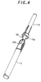
- Fig.4 is a perspective view showing the embodiment immediately before use.
- FIG.1 Shown in Fig.1 is an indwelling needle comprised of a hard inner needle 12 which punctures the skin and reaches the vein, a soft outer needle 11 which is located outside of inner needle 12 and is indwelled within the vein, and a container barrel 1 incorporating an inner needle retraction mechanism for retracting inner needle 12 after use.
- the indwelling needle body includes soft-resin made a hollow outer needle 11 which has a thin-walled distal part producing an increased contact with inner needle 12. This distal part is formed in hermetic contact with inner needle 12 so as not to easily come away.
- a hub lla for connection with a medical tube such as drip infusion tube.
- a flange 11b is formed in hub 11a on its proximal side.
- Inner needle 12 is of a hollow stainless steel needle, beveled at its tip forming a needle edge. On the proximal side of the inner needle, a cylindrical attachment part 12a inserted into hub lla of outer needle 11 and a cylindrical joint part 12b coupled with an actuator 6 as a part of an aftermentioned retraction mechanism are continuously formed. A cylindrical resin-made filter 12c is stuffed at the end of joint part 12b.
- inner needle 12 is not limited to hollow needles, but any hard type needle, e.g., a solid needle, may be used.
- a container barrel 1 is a cylindrical sleeve for retracting inner needle 12 therein and incorporates the inner needle retraction mechanism and is long enough so that inner needle 12 can be retracted therein by the inner needle retraction mechanism.
- the inner needle retraction mechanism is comprised of a tail plug 9 fixed at the proximal end of container barrel 1, a coil spring 8 circumferentially fixed at its proximal end to the tail plug 9, an actuator 6 fixed to the distal end of coil spring 8 and also fixed to joint part 12b of inner needle 12.
- Actuator 6 is positioned on the distal side of container barrel 1 and fixed therein until puncture of inner needle 12 and outer needle 11 to the patient is completed (to be referred to as 'during use' hereinbelow). In this state, coil spring 8 is stretched under loading. When inner needle 12 has been pulled out (to be referred to as 'after the use of inner needle 12'), actuator 6 is adapted to move toward the proximal end of container barrel 1 by the elastic force of coil spring 8. Next, the configuration of actuator 6 and container barrel 1 will be described in further detail.
- Actuator 6 is comprised of a cylindrical attachment part 6d to which joint part 12b of inner needle 12 can be inserted and fixed, a plate-like rib 6c axially supporting joint part 12b of inner needle 12 fitted in attachment part 6d and a plate-like actuator piece 6a elongated in the axial direction of rib 6c and attachment part 6d and projected in the radially outward direction of actuator 6.
- a guide groove 2 is formed in container barrel 1 between the point at which actuator 6 is positioned during use and the point at which actuator 6 is positioned after use so that actuator piece 6a of actuator 6 can be projected out from container barrel 1 through guide groove 2.
- a window-like in-use fixing portion 3 continuous from guide groove 2 is formed at the position where actuator 6 is to be placed during use.
- This in-use fixing portion 3 is formed equal in size to the length of actuator piece 6a so that actuator piece 6a is projected outwardly from container barrel 1 and has a projection 3a for preventing malfunction at the boundary with guide groove 2. This projection 3a prevents actuator piece 6a from slipping from in-use fixing portion 3 into guide groove 2 during use.
- a window-like after-use fixing portion 4 continuous from guide groove 2 is formed at the position where actuator 6 is to be placed after use.
- This after-use fixing portion 4 is formed greater in size than the length of actuator piece 6a so that actuator piece 6a is projected outwardly from container barrel 1 and is formed with a retraction projection 4a at the position corresponding to the length of actuator piece 6a.
- This retraction projection 4a engages actuator piece 6a when actuator piece 6a is moved back to the proximal side of container barrel 1 and fixes actuator 6 at that position.
- tail plug catch 5 Formed at the proximal end of container barrel 1 is a cutout portion forming a tail plug catch 5 for fixing tail plug 9 .
- This tail plug catch 5 is a cutout of half-arrowheaded shape and a mating engaging portion 9a is formed on the tail plug 9 side.
- an outer needle support lid 20 is circumferentially fitted and fixed on the distal end of container barrel 1.
- This outer needle support lid 20 has a gutter-like portion 20d, which is a short cylinder with a cutout portion 20c cut away from its side.
- this outer lid 20 further includes a fixing piece 20b to be fixed to the outer periphery at the distal end of container barrel 1 and a joint portion 20a located between fixing piece 20b and gutter-like portion 20d.
- gutter-like portion 20d The inside diameter of gutter-like portion 20d is greater than the outside dimension of attachment part 12a(Fig.1) of inner needle 12 so as to allow attachment part 12a of inner needle 12 to be inserted but is smaller than the outside dimension of flange 11b of outer needle 11. Therefore, even when inner needle 12 is retracted into container barrel 1 by the function of the inner needle retraction mechanism, outer needle 11 will not be withdrawn into container barrel 1 because flange 11b abuts against gutter-like portion 20d.
- outer needle support lid 20 is fixed to container barrel 1 in such a manner that cutout portion 20c is placed in proximity to the position of actuator piece 6a of actuator 6 during use.
- actuator piece 6a positioned at in-use fixing portion 3(Fig.1) is moved by the finger so as to ride over projection 3a for preventing malfunction(Fig.1) and be guided to guide groove 2. Then, coil spring 8(Fig.1) contracts and causes actuator 6 to move to the proximal side of container barrel 1. In this movement, actuator piece 6a moves along guide groove 2 to after-use fixing portion 4(Fig.1). Then, the actuator piece 6a now positioned at after-use fixing portion 4 is further moved back and engaged with retraction projection 4a. Thereby, actuator 6 is fixed circumferentially at that position, whereby inner needle 12 attached to actuator 6 will not erroneously come out from container barrel 1, thus making it possible to reduce the risk of occurrence of accidental needlesticks.
- cutout portion 20c of outer needle support lid 20 is positioned in proximity to actuator 6a when it is positioned on the distal side, it is possible to perform the pulling action of inner needle 12 while holding hub 11a of outer needle 11 and the action of moving actuator piece 6a for causing retraction of inner needle 12 into container barrel 1, without changing the grip of container barrel 1.
- Fig.3 shows this indwelling needle shown in Figs.1 and 2, before it is used, i.e., with inner and outer needles 12 and 11 covered with a cap 13.
- This cap 13 has a short cylindrical portion 13a enclosing the distal part of container barrel 1. Since the indwelling needle injection device according to this embodiment is thus capped with cap 13 and is packaged and distributed, the device becomes ready for use at once by uncapping cap 13.
- Fig.4 shows the rear side of the indwelling needle shown in Fig.3.
- Cap 13 has short cylindrical portion 13a enclosing the peripheral side of distal part of container barrel 1. The short cylindrical portion 13a is cut out at the position corresponding to fixing piece 20b of outer needle support lid 20, forming a fixing piece mating cutout 13b.
- an indwelling needle which allows the inner needle to be retracted without causing retraction of the outer needle due to malfunction and will not deteriorate readiness in handling.
Abstract
Description
- The present invention relates to a technology of an indwelling needle comprised of a hard inner needle which punctures the skin and reaches the vein and a soft outer needle which is located outside of the inner needle and is indwelled within the vein and is directed to an indwelling needle with an inner needle retraction mechanism.
- Various techniques have been proposed in order to prevent secondary infection.
- For example, Japanese Patent Application Laid-Open Hei 9 No. 629 is directed to an 'indwelling needle' which aims at 'safety disposal of the inner needle of the used indwelling needle without any risk of the workers concerned being secondarily infected' and has a 'configuration which enables the inner needle to be fixed within the protection cover'.
- Since a typical indwelling needle is comprised of a resin-made outer needle and a stainless inner needle, the risk of secondary infection due to 'needlestick injuries' arises from the inner needle. Therefore, other than that disclosed in Japanese Patent Application Laid-Open Hei 9 No. 629, there are several techniques of confining the inner needle, which would cause erroneous or accidental prick, within a tubular sleeve.
- In general, the tubular sleeve keeps the inner needle therein and does not retract the outer needle. With regards to the mechanism for retraction, the mechanism preferably has a device for preventing the outer needle from being drawn into the tubular sleeve even if the mechanism malfunctions during and/or after the puncture of the inner and outer needles to the patient's skin. With this device, it is possible to secure necessary safety during the treatment and eliminate the burden on the patient due to doing over again. However, if the countermeasure against such a malfunction is attempted by devising inner needle retraction arrangements, a complex mechanism will be needed and also a troublesome operation for retraction of the inner needle will be needed.
- Both the inner and outer needles are made to puncture the patient's skin and only the inner needle is pulled out while the outer needle remains therein. When the inner needle is pulled, in order to prevent the outer needle from being removed together with the inner needle, it is necessary to apply the finger around the contact area between the outer needle and the skin and/or the proximal part of the outer needle. In this case, if any projection is present around the proximal part of the outer needle, it is not desirable for 'the finger that is applied on the outer needle proximal part' because such a projection deteriorates fastness and readiness in handling.
- It is therefore an object of the present invention to provide an indwelling needle with an inner needle retraction mechanism which is capable of retracting the inner needle, disallows the outer needle to be withdrawn by any malfunction and will not reduce fastness and readiness in handling.
- It is another object of the present invention to provide an indwelling needle with an inner needle retraction mechanism which provides readiness in retracting the inner needle.
- In order to achieve the above objects, the present invention is configured as follows:
- The present invention is directed to an indwelling needle including a hard inner needle(12), a soft outer needle(11) and an inner needle retraction mechanism. That is, the present invention relates to an indwelling needle with an inner needle retraction mechanism, has a container barrel(1) having distal and proximal ends, and having an inner needle retraction mechanism (including an
actuator 6 and urging element 8) for holding the inner needle(12) after use therein; and an outer needle support lid element(20) fixed at the distal end of the container barrel(1) for prohibiting the outer needle(11) from being withdrawn into the container barrel(1), and is characterized in that the outer needle support lid element(20) has a gutter-like portion, which is a short cylinder formed in part with a cutout portion(20C) and the inside dimension thereof is designed so as to allow the inner needle(12) to pass therethrough and be smaller than the outside dimension of the hub (11a) (more exactly, aflange 11b ofhub 11a) of the outer needle(11). - In accordance with the above configuration of the present invention, the outer needle(11) together with the inner needle(12) is made to puncture the skin and reach the vein. Then, the inner needle(12) is withdrawn while the hub (11a) of the outer needle(11) being held. During this procedure, since the outer needle support lid(20) has the cutout portion(20c), the finger is able to hold the hub (11a) of the outer needle(11) without any obstruction. At this point, if the retraction mechanism(6 and 8) operates, the outer needle(11) will not be withdrawn into the container barrel(1) because there exists the outer needle support lid(20) having an inside dimension smaller than the outside dimension of the hub (11a) of the outer needle(11).
- After the inner needle(12) is pulled out, an fluid injection tube for injection to the patient body such as an drip infusion tube is connected to the hub (11a) of the outer needle(11).
- In the present invention, the inner needle retraction mechanism may be comprised of a guide groove(2) formed in the container barrel(1) in the longitudinal direction thereof, an actuator(6) fixed to the inner needle(12) and having an actuator piece(6a) for causing the inner needle(12) to be retracted into the container barrel(1) and an urging element(8) for urging the actuator(6) to the proximal side of the container barrel(1), and the cutout portion(20c) of the outer needle support lid element(20) may be positioned in proximity to the actuator piece(6a).
- In this case, since the cutout portion(20c) of outer needle support lid element(20) is positioned in proximity to the actuator piece(6a), it is possible to perform the pulling action of the inner needle(12) while holding the hub (11a) of the outer needle(11) and the action of causing retraction of the inner needle(12) into the container barrel(1), without changing the grip of the container barrel(1).
-
- Fig.1 is an exploded perspective view showing the embodiment of the present invention;
- Fig.2 is a perspective view showing the embodiment of the present invention in its use state;
- Fig.3 is a perspective view showing the embodiment before use; and
- Fig.4 is a perspective view showing the embodiment immediately before use.
-
- The present invention will hereinafter be described in detail with reference to the embodiment and the accompanying drawings. The drawings used here include Figs.1 through 4. Fig.1 is an exploded perspective view showing the embodiment of the present invention. Fig.2 is a perspective view showing the embodiment of the present invention in its use state. Fig.3 is a perspective view showing the embodiment before use. Fig.4 is a perspective view showing the embodiment immediately before use.
- Shown in Fig.1 is an indwelling needle comprised of a hard
inner needle 12 which punctures the skin and reaches the vein, a soft outer needle 11 which is located outside ofinner needle 12 and is indwelled within the vein, and a container barrel 1 incorporating an inner needle retraction mechanism for retractinginner needle 12 after use. - The indwelling needle body, designated at 10, includes soft-resin made a hollow outer needle 11 which has a thin-walled distal part producing an increased contact with
inner needle 12. This distal part is formed in hermetic contact withinner needle 12 so as not to easily come away. Provided at the proximal end of the outer needle is a hub lla for connection with a medical tube such as drip infusion tube. Aflange 11b is formed inhub 11a on its proximal side. -
Inner needle 12 is of a hollow stainless steel needle, beveled at its tip forming a needle edge. On the proximal side of the inner needle, acylindrical attachment part 12a inserted into hub lla of outer needle 11 and a cylindricaljoint part 12b coupled with anactuator 6 as a part of an aftermentioned retraction mechanism are continuously formed. A cylindrical resin-madefilter 12c is stuffed at the end ofjoint part 12b. Here,inner needle 12 is not limited to hollow needles, but any hard type needle, e.g., a solid needle, may be used. - A container barrel 1 is a cylindrical sleeve for retracting
inner needle 12 therein and incorporates the inner needle retraction mechanism and is long enough so thatinner needle 12 can be retracted therein by the inner needle retraction mechanism. The inner needle retraction mechanism is comprised of atail plug 9 fixed at the proximal end of container barrel 1, a coil spring 8 circumferentially fixed at its proximal end to thetail plug 9, anactuator 6 fixed to the distal end of coil spring 8 and also fixed tojoint part 12b ofinner needle 12. -
Actuator 6 is positioned on the distal side of container barrel 1 and fixed therein until puncture ofinner needle 12 and outer needle 11 to the patient is completed (to be referred to as 'during use' hereinbelow). In this state, coil spring 8 is stretched under loading. Wheninner needle 12 has been pulled out (to be referred to as 'after the use of inner needle 12'),actuator 6 is adapted to move toward the proximal end of container barrel 1 by the elastic force of coil spring 8. Next, the configuration ofactuator 6 and container barrel 1 will be described in further detail. -
Actuator 6 is comprised of acylindrical attachment part 6d to whichjoint part 12b ofinner needle 12 can be inserted and fixed, a plate-like rib 6c axially supportingjoint part 12b ofinner needle 12 fitted inattachment part 6d and a plate-like actuator piece 6a elongated in the axial direction ofrib 6c andattachment part 6d and projected in the radially outward direction ofactuator 6. - A
guide groove 2 is formed in container barrel 1 between the point at whichactuator 6 is positioned during use and the point at whichactuator 6 is positioned after use so thatactuator piece 6a ofactuator 6 can be projected out from container barrel 1 throughguide groove 2. In order to stably fixactuator 6 during use, a window-like in-use fixing portion 3 continuous fromguide groove 2 is formed at the position whereactuator 6 is to be placed during use. This in-use fixing portion 3 is formed equal in size to the length ofactuator piece 6a so thatactuator piece 6a is projected outwardly from container barrel 1 and has aprojection 3a for preventing malfunction at the boundary withguide groove 2. Thisprojection 3a preventsactuator piece 6a from slipping from in-use fixing portion 3 intoguide groove 2 during use. - Further, in order to stably fix
actuator 6 after use, a window-like after-use fixing portion 4 continuous fromguide groove 2 is formed at the position whereactuator 6 is to be placed after use. This after-use fixing portion 4 is formed greater in size than the length ofactuator piece 6a so thatactuator piece 6a is projected outwardly from container barrel 1 and is formed with aretraction projection 4a at the position corresponding to the length ofactuator piece 6a. Thisretraction projection 4a engagesactuator piece 6a whenactuator piece 6a is moved back to the proximal side of container barrel 1 and fixesactuator 6 at that position. - Formed at the proximal end of container barrel 1 is a cutout portion forming a tail plug catch 5 for
fixing tail plug 9 . This tail plug catch 5 is a cutout of half-arrowheaded shape and a matingengaging portion 9a is formed on thetail plug 9 side. - In order to prevent outer needle 11 from being withdrawn into container barrel 1, an outer
needle support lid 20 is circumferentially fitted and fixed on the distal end of container barrel 1. This outerneedle support lid 20 has a gutter-like portion 20d, which is a short cylinder with acutout portion 20c cut away from its side. In order to fix this outerneedle support lid 20 to container barrel 1, thisouter lid 20 further includes a fixingpiece 20b to be fixed to the outer periphery at the distal end of container barrel 1 and ajoint portion 20a located between fixingpiece 20b and gutter-like portion 20d. The inside diameter of gutter-like portion 20d is greater than the outside dimension ofattachment part 12a(Fig.1) ofinner needle 12 so as to allowattachment part 12a ofinner needle 12 to be inserted but is smaller than the outside dimension offlange 11b of outer needle 11. Therefore, even wheninner needle 12 is retracted into container barrel 1 by the function of the inner needle retraction mechanism, outer needle 11 will not be withdrawn into container barrel 1 becauseflange 11b abuts against gutter-like portion 20d. - Here, outer
needle support lid 20 is fixed to container barrel 1 in such a manner that cutoutportion 20c is placed in proximity to the position ofactuator piece 6a ofactuator 6 during use. - Referring next to Fig.2, the operation during use will be described.
- Outer needle 11 of
indwelling needle body 10 together withinner needle 12 punctures the skin and reaches the vein. Then,inner needle 12 is pulled out whilehub 11a of outer needle 11 being held. During this procedure, since outerneedle support lid 20 hascutout portion 20c, the finger is able to holdhub 11a of outer needle 11 without any obstruction. At this point, if retraction mechanism(actuator 6 and coil spring 8) operates, outer needle 11 will not be withdrawn into container barrel 1 because there exists outerneedle support lid 20 having an inside dimension smaller than the outside dimension offlange 11b ofhub 11a of outer needle 11. - After
inner needle 12 is pulled out,actuator piece 6a positioned at in-use fixing portion 3(Fig.1) is moved by the finger so as to ride overprojection 3a for preventing malfunction(Fig.1) and be guided to guidegroove 2. Then, coil spring 8(Fig.1) contracts and causesactuator 6 to move to the proximal side of container barrel 1. In this movement,actuator piece 6a moves alongguide groove 2 to after-use fixing portion 4(Fig.1). Then, theactuator piece 6a now positioned at after-use fixing portion 4 is further moved back and engaged withretraction projection 4a. Thereby,actuator 6 is fixed circumferentially at that position, wherebyinner needle 12 attached toactuator 6 will not erroneously come out from container barrel 1, thus making it possible to reduce the risk of occurrence of accidental needlesticks. - Since
cutout portion 20c of outerneedle support lid 20 is positioned in proximity toactuator 6a when it is positioned on the distal side, it is possible to perform the pulling action ofinner needle 12 while holdinghub 11a of outer needle 11 and the action of movingactuator piece 6a for causing retraction ofinner needle 12 into container barrel 1, without changing the grip of container barrel 1. - Fig.3 shows this indwelling needle shown in Figs.1 and 2, before it is used, i.e., with inner and
outer needles 12 and 11 covered with acap 13. Thiscap 13 has a shortcylindrical portion 13a enclosing the distal part of container barrel 1. Since the indwelling needle injection device according to this embodiment is thus capped withcap 13 and is packaged and distributed, the device becomes ready for use at once by uncappingcap 13. - Fig.4 shows the rear side of the indwelling needle shown in Fig.3.
Cap 13 has shortcylindrical portion 13a enclosing the peripheral side of distal part of container barrel 1. The shortcylindrical portion 13a is cut out at the position corresponding to fixingpiece 20b of outerneedle support lid 20, forming a fixingpiece mating cutout 13b. - According to the present invention, it is possible to provide an indwelling needle which allows the inner needle to be retracted without causing retraction of the outer needle due to malfunction and will not deteriorate readiness in handling.
- It is also possible to provide an indwelling needle which can be easily handled in retracting the inner needle into the device body.
Claims (2)
- An indwelling needle with an inner needle retraction mechanism comprising:characterized in that the outer needle support lid element has a gutter-like portion, which is a short cylinder formed in part with a cutout portion and an inside dimension thereof is designed so as to allow the inner needle to pass therethrough and be smaller than an outside dimension of a hub of the outer needle.the indwelling needle including a hard inner needle and a soft outer needle;a container barrel having distal and proximal ends, and incorporating the inner needle retraction mechanism for retracting the inner needle after use therein; andan outer needle support lid element fixed at the distal end of the container barrel for prohibiting the outer needle from being withdrawn into the container barrel,
- The indwelling needle according to Claim 1, wherein the inner needle retraction mechanism is comprised of a guide groove formed in the container barrel in the longitudinal direction thereof, an actuator fixed to the inner needle and having an actuator piece for causing the inner needle to be retracted into the container barrel and an urging element for urging the actuator to the proximal side of the container barrel, and the cutout portion of the outer needle support lid element is positioned in proximity to the actuator piece.
Applications Claiming Priority (2)
| Application Number | Priority Date | Filing Date | Title |
|---|---|---|---|
| JP2000043058 | 2000-02-21 | ||
| JP2000043058A JP2001231857A (en) | 2000-02-21 | 2000-02-21 | Indwelling needle with inner needle storage mechanism |
Publications (3)
| Publication Number | Publication Date |
|---|---|
| EP1127584A2 true EP1127584A2 (en) | 2001-08-29 |
| EP1127584A3 EP1127584A3 (en) | 2003-03-19 |
| EP1127584B1 EP1127584B1 (en) | 2005-11-23 |
Family
ID=18566035
Family Applications (1)
| Application Number | Title | Priority Date | Filing Date |
|---|---|---|---|
| EP01103918A Expired - Lifetime EP1127584B1 (en) | 2000-02-21 | 2001-02-17 | Indwelling needle with an inner needle retraction mechanism |
Country Status (5)
| Country | Link |
|---|---|
| US (1) | US6676638B2 (en) |
| EP (1) | EP1127584B1 (en) |
| JP (1) | JP2001231857A (en) |
| DE (1) | DE60115119T2 (en) |
| ES (1) | ES2248177T3 (en) |
Cited By (1)
| Publication number | Priority date | Publication date | Assignee | Title |
|---|---|---|---|---|
| WO2007003379A1 (en) * | 2005-07-01 | 2007-01-11 | Covidien Ag | Packaging container for indwelling needle |
Families Citing this family (25)
| Publication number | Priority date | Publication date | Assignee | Title |
|---|---|---|---|---|
| US20060089599A1 (en) * | 2004-10-27 | 2006-04-27 | Daniel Lynn | Blood donor needle assembly and cover |
| US20070060890A1 (en) * | 2005-09-08 | 2007-03-15 | Cuppy Medical Products, Inc. | Catheter safety tube needle retraction system |
| US7682341B2 (en) * | 2005-11-09 | 2010-03-23 | Medikit Co., Ltd | Indwelling needle |
| GB0600212D0 (en) * | 2006-01-06 | 2006-02-15 | Liversidge Barry P | Medical needle safety device |
| US7856751B1 (en) * | 2007-01-23 | 2010-12-28 | Alien Products, Incorporated | Dual purpose fishing tool |
| US8313458B2 (en) * | 2007-03-30 | 2012-11-20 | Wenjie Liu | Barrel type plunger for use with a needle-retractable safety syringe and the syringe using the same |
| US7676982B1 (en) * | 2008-03-19 | 2010-03-16 | San Fu Lee | Method and apparatus for venting fish |
| US8348938B2 (en) * | 2008-05-06 | 2013-01-08 | Old Dominian University Research Foundation | Apparatus, systems and methods for treating a human tissue condition |
| US7934336B2 (en) * | 2008-07-03 | 2011-05-03 | Cooksey Thomas C | Fish pressure equilibrating tool |
| US20100298825A1 (en) * | 2009-05-08 | 2010-11-25 | Cellutions, Inc. | Treatment System With A Pulse Forming Network For Achieving Plasma In Tissue |
| US8377034B2 (en) | 2009-12-04 | 2013-02-19 | Std Med, Inc. | Vascular access port |
| US8128594B1 (en) * | 2010-11-03 | 2012-03-06 | Chang li-feng | Safety syringe |
| AU344165S (en) | 2012-02-02 | 2012-09-04 | Terumo Corp | Indwelling needle with safety device |
| AU344164S (en) | 2012-02-02 | 2012-09-04 | Terumo Corp | Safety device for indwelling needle |
| WO2014047889A1 (en) * | 2012-09-28 | 2014-04-03 | Zhang Jianming | Soft tube detaining infusion apparatus with combined and connected tube-needle |
| WO2014047891A1 (en) * | 2012-09-28 | 2014-04-03 | Zhang Jianming | Soft tube detaining scalp needle with combined and connected tube-needle |
| CN103143080B (en) * | 2013-01-11 | 2016-05-11 | 英属维尔京群岛圣采科技投资有限公司 | High-safety needle staying on vein |
| US10369345B2 (en) | 2014-03-31 | 2019-08-06 | Versago Vascular Access, Inc. | Medical access port, systems and methods of use thereof |
| US9764124B2 (en) | 2014-03-31 | 2017-09-19 | Versago Vascular Access, Inc. | Vascular access port |
| US10512734B2 (en) | 2014-04-03 | 2019-12-24 | Versago Vascular Access, Inc. | Devices and methods for installation and removal of a needle tip of a needle |
| EP3233175B1 (en) | 2014-12-18 | 2019-03-13 | Versago Vascular Access, Inc. | Devices for removal and replacement of a catheter for an implanted access port |
| US11154687B2 (en) | 2014-12-18 | 2021-10-26 | Versago Vascular Access, Inc. | Catheter patency systems and methods |
| WO2016179795A1 (en) * | 2015-05-12 | 2016-11-17 | 福建省百仕韦医用高分子股份有限公司 | Open catheter needle with slotted protection sleeve |
| JP6879946B2 (en) * | 2015-07-14 | 2021-06-02 | ヴェルサゴ ヴァスキュラー アクセス インコーポレイテッド | Medical access ports, transport devices and how to use them |
| US11058815B2 (en) | 2017-12-21 | 2021-07-13 | Versago Vascular Access, Inc. | Medical access ports, transfer devices and methods of use thereof |
Citations (3)
| Publication number | Priority date | Publication date | Assignee | Title |
|---|---|---|---|---|
| US5279590A (en) * | 1992-08-21 | 1994-01-18 | Gesco International, Inc. | Catheter placement apparatus |
| JPH09629A (en) * | 1995-06-16 | 1997-01-07 | Togo Medikit Kk | Implant type needle |
| US5993470A (en) * | 1992-09-15 | 1999-11-30 | Yoon; Inbae | Universal handle for medical instruments |
Family Cites Families (7)
| Publication number | Priority date | Publication date | Assignee | Title |
|---|---|---|---|---|
| NZ237373A (en) | 1990-03-22 | 1993-07-27 | Critikon Inc | Catheter assembly: nose of needle guard engages in an interference fit with catheter hub |
| US5215528C1 (en) * | 1992-02-07 | 2001-09-11 | Becton Dickinson Co | Catheter introducer assembly including needle tip shield |
| SE502537C2 (en) * | 1992-11-26 | 1995-11-06 | Boc Ohmeda Ab | Device for infusion cannula |
| JPH0724071A (en) * | 1993-07-09 | 1995-01-27 | Terumo Corp | Blood vessel indwelling catheter |
| US5865806A (en) * | 1996-04-04 | 1999-02-02 | Becton Dickinson And Company | One step catheter advancement automatic needle retraction system |
| JP4245196B2 (en) | 1996-07-03 | 2009-03-25 | 東郷メディキット株式会社 | Medical puncture device |
| US5954698A (en) * | 1997-01-08 | 1999-09-21 | Vadus, Inc. | Catheter apparatus having valved catheter hub and needle protector |
-
2000
- 2000-02-21 JP JP2000043058A patent/JP2001231857A/en active Pending
-
2001
- 2001-02-08 US US09/779,173 patent/US6676638B2/en not_active Expired - Fee Related
- 2001-02-17 ES ES01103918T patent/ES2248177T3/en not_active Expired - Lifetime
- 2001-02-17 DE DE60115119T patent/DE60115119T2/en not_active Expired - Lifetime
- 2001-02-17 EP EP01103918A patent/EP1127584B1/en not_active Expired - Lifetime
Patent Citations (3)
| Publication number | Priority date | Publication date | Assignee | Title |
|---|---|---|---|---|
| US5279590A (en) * | 1992-08-21 | 1994-01-18 | Gesco International, Inc. | Catheter placement apparatus |
| US5993470A (en) * | 1992-09-15 | 1999-11-30 | Yoon; Inbae | Universal handle for medical instruments |
| JPH09629A (en) * | 1995-06-16 | 1997-01-07 | Togo Medikit Kk | Implant type needle |
Non-Patent Citations (1)
| Title |
|---|
| PATENT ABSTRACTS OF JAPAN vol. 1997, no. 05, 30 May 1997 (1997-05-30) -& JP 09 000629 A (TOGO MEDIKIT KK), 7 January 1997 (1997-01-07) * |
Cited By (1)
| Publication number | Priority date | Publication date | Assignee | Title |
|---|---|---|---|---|
| WO2007003379A1 (en) * | 2005-07-01 | 2007-01-11 | Covidien Ag | Packaging container for indwelling needle |
Also Published As
| Publication number | Publication date |
|---|---|
| ES2248177T3 (en) | 2006-03-16 |
| EP1127584A3 (en) | 2003-03-19 |
| DE60115119T2 (en) | 2006-07-27 |
| DE60115119D1 (en) | 2005-12-29 |
| JP2001231857A (en) | 2001-08-28 |
| EP1127584B1 (en) | 2005-11-23 |
| US6676638B2 (en) | 2004-01-13 |
| US20010016713A1 (en) | 2001-08-23 |
Similar Documents
| Publication | Publication Date | Title |
|---|---|---|
| EP1127584B1 (en) | Indwelling needle with an inner needle retraction mechanism | |
| US6761706B2 (en) | Needle guard | |
| EP0510187B1 (en) | Catheter assembly having safety means and method for using same | |
| EP1221303B1 (en) | Blood collection set | |
| US5549571A (en) | Butterfly assembly with retractable needle cannula | |
| US7201740B2 (en) | Forward-shielding blood collection set | |
| EP0702972B1 (en) | Safety shield having spring tether | |
| US8603043B2 (en) | Needle sheathing device with flexible end-piece for syringe | |
| US4846811A (en) | Sliding sheath for medical needles | |
| US5478313A (en) | Needle shield | |
| US7214211B2 (en) | Needle assembly with protective element | |
| US5573512A (en) | Infusion or transfusion needle assembly | |
| EP0639386A1 (en) | Self contained needle and shield | |
| EP2905042B1 (en) | Medical safety needle which prevents re-exposure of needle tip | |
| US5817060A (en) | Unidirectional blunting apparatus for hypodermic needles | |
| CN115715831A (en) | Manual injection device | |
| US20070123830A1 (en) | Safety syringe | |
| US5512050A (en) | Needle assembly with collapsible and retractable sheath | |
| WO1997042989A1 (en) | Catheter placement device | |
| EP1621221A1 (en) | Medical needle device having shield with wings | |
| JP4844259B2 (en) | Method for manufacturing a needle assembly | |
| AU2007216913B2 (en) | Protective device for a hypodermic needle | |
| CA2364972A1 (en) | Blood collection set |
Legal Events
| Date | Code | Title | Description |
|---|---|---|---|
| PUAI | Public reference made under article 153(3) epc to a published international application that has entered the european phase |
Free format text: ORIGINAL CODE: 0009012 |
|
| AK | Designated contracting states |
Kind code of ref document: A2 Designated state(s): AT BE CH CY DE DK ES FI FR GB GR IE IT LI LU MC NL PT SE TR |
|
| AX | Request for extension of the european patent |
Free format text: AL;LT;LV;MK;RO;SI |
|
| PUAL | Search report despatched |
Free format text: ORIGINAL CODE: 0009013 |
|
| AK | Designated contracting states |
Kind code of ref document: A3 Designated state(s): AT BE CH CY DE DK ES FI FR GB GR IE IT LI LU MC NL PT SE TR |
|
| AX | Request for extension of the european patent |
Extension state: AL LT LV MK RO SI |
|
| 17P | Request for examination filed |
Effective date: 20030523 |
|
| AKX | Designation fees paid |
Designated state(s): DE ES FR GB IT |
|
| 17Q | First examination report despatched |
Effective date: 20040706 |
|
| GRAP | Despatch of communication of intention to grant a patent |
Free format text: ORIGINAL CODE: EPIDOSNIGR1 |
|
| GRAS | Grant fee paid |
Free format text: ORIGINAL CODE: EPIDOSNIGR3 |
|
| GRAA | (expected) grant |
Free format text: ORIGINAL CODE: 0009210 |
|
| AK | Designated contracting states |
Kind code of ref document: B1 Designated state(s): DE ES FR GB IT |
|
| REG | Reference to a national code |
Ref country code: GB Ref legal event code: FG4D |
|
| REF | Corresponds to: |
Ref document number: 60115119 Country of ref document: DE Date of ref document: 20051229 Kind code of ref document: P |
|
| REG | Reference to a national code |
Ref country code: ES Ref legal event code: FG2A Ref document number: 2248177 Country of ref document: ES Kind code of ref document: T3 |
|
| ET | Fr: translation filed | ||
| PLBE | No opposition filed within time limit |
Free format text: ORIGINAL CODE: 0009261 |
|
| STAA | Information on the status of an ep patent application or granted ep patent |
Free format text: STATUS: NO OPPOSITION FILED WITHIN TIME LIMIT |
|
| 26N | No opposition filed |
Effective date: 20060824 |
|
| REG | Reference to a national code |
Ref country code: DE Ref legal event code: R082 Ref document number: 60115119 Country of ref document: DE Representative=s name: OPPERMANN, FRANK, DIPL.-ING., DE Ref country code: DE Ref legal event code: R082 Ref document number: 60115119 Country of ref document: DE Representative=s name: FRANK OPPERMANN, DE |
|
| REG | Reference to a national code |
Ref country code: FR Ref legal event code: PLFP Year of fee payment: 15 |
|
| REG | Reference to a national code |
Ref country code: FR Ref legal event code: PLFP Year of fee payment: 16 |
|
| REG | Reference to a national code |
Ref country code: FR Ref legal event code: PLFP Year of fee payment: 17 |
|
| REG | Reference to a national code |
Ref country code: FR Ref legal event code: PLFP Year of fee payment: 18 |
|
| PGFP | Annual fee paid to national office [announced via postgrant information from national office to epo] |
Ref country code: GB Payment date: 20200206 Year of fee payment: 20 Ref country code: ES Payment date: 20200302 Year of fee payment: 20 Ref country code: IT Payment date: 20200128 Year of fee payment: 20 Ref country code: DE Payment date: 20200204 Year of fee payment: 20 |
|
| PGFP | Annual fee paid to national office [announced via postgrant information from national office to epo] |
Ref country code: FR Payment date: 20200113 Year of fee payment: 20 |
|
| REG | Reference to a national code |
Ref country code: DE Ref legal event code: R071 Ref document number: 60115119 Country of ref document: DE |
|
| REG | Reference to a national code |
Ref country code: GB Ref legal event code: PE20 Expiry date: 20210216 |
|
| PG25 | Lapsed in a contracting state [announced via postgrant information from national office to epo] |
Ref country code: GB Free format text: LAPSE BECAUSE OF EXPIRATION OF PROTECTION Effective date: 20210216 |
|
| REG | Reference to a national code |
Ref country code: ES Ref legal event code: FD2A Effective date: 20211203 |
|
| PG25 | Lapsed in a contracting state [announced via postgrant information from national office to epo] |
Ref country code: ES Free format text: LAPSE BECAUSE OF EXPIRATION OF PROTECTION Effective date: 20210218 |