EP1128773B1 - Reverse angle thread for preventing splaying in medical devices - Google Patents
Reverse angle thread for preventing splaying in medical devices Download PDFInfo
- Publication number
- EP1128773B1 EP1128773B1 EP99956907A EP99956907A EP1128773B1 EP 1128773 B1 EP1128773 B1 EP 1128773B1 EP 99956907 A EP99956907 A EP 99956907A EP 99956907 A EP99956907 A EP 99956907A EP 1128773 B1 EP1128773 B1 EP 1128773B1
- Authority
- EP
- European Patent Office
- Prior art keywords
- medical device
- thread
- receiver member
- bore
- bone
- Prior art date
- Legal status (The legal status is an assumption and is not a legal conclusion. Google has not performed a legal analysis and makes no representation as to the accuracy of the status listed.)
- Expired - Lifetime
Links
- 210000000988 bone and bone Anatomy 0.000 claims description 33
- 230000000399 orthopedic effect Effects 0.000 claims description 5
- 239000007943 implant Substances 0.000 description 10
- 238000002513 implantation Methods 0.000 description 4
- 230000008901 benefit Effects 0.000 description 3
- 208000027418 Wounds and injury Diseases 0.000 description 2
- 230000006378 damage Effects 0.000 description 2
- 208000014674 injury Diseases 0.000 description 2
- 238000012986 modification Methods 0.000 description 2
- 230000004048 modification Effects 0.000 description 2
- 208000032170 Congenital Abnormalities Diseases 0.000 description 1
- 229910001200 Ferrotitanium Inorganic materials 0.000 description 1
- RTAQQCXQSZGOHL-UHFFFAOYSA-N Titanium Chemical compound [Ti] RTAQQCXQSZGOHL-UHFFFAOYSA-N 0.000 description 1
- 230000004075 alteration Effects 0.000 description 1
- 239000000560 biocompatible material Substances 0.000 description 1
- 230000006835 compression Effects 0.000 description 1
- 238000007906 compression Methods 0.000 description 1
- 201000010099 disease Diseases 0.000 description 1
- 208000037265 diseases, disorders, signs and symptoms Diseases 0.000 description 1
- 230000008030 elimination Effects 0.000 description 1
- 238000003379 elimination reaction Methods 0.000 description 1
- 230000035876 healing Effects 0.000 description 1
- 210000003041 ligament Anatomy 0.000 description 1
- 239000000463 material Substances 0.000 description 1
- 238000005259 measurement Methods 0.000 description 1
- 229910052751 metal Inorganic materials 0.000 description 1
- 239000002184 metal Substances 0.000 description 1
- 150000002739 metals Chemical class 0.000 description 1
- 210000003205 muscle Anatomy 0.000 description 1
- 230000001737 promoting effect Effects 0.000 description 1
- 230000000717 retained effect Effects 0.000 description 1
- 230000000087 stabilizing effect Effects 0.000 description 1
- 229910001220 stainless steel Inorganic materials 0.000 description 1
- 239000010935 stainless steel Substances 0.000 description 1
- 238000001356 surgical procedure Methods 0.000 description 1
- 210000002435 tendon Anatomy 0.000 description 1
- 230000001225 therapeutic effect Effects 0.000 description 1
- 239000010936 titanium Substances 0.000 description 1
Images

Classifications
-
- A—HUMAN NECESSITIES
- A61—MEDICAL OR VETERINARY SCIENCE; HYGIENE
- A61B—DIAGNOSIS; SURGERY; IDENTIFICATION
- A61B17/00—Surgical instruments, devices or methods, e.g. tourniquets
- A61B17/56—Surgical instruments or methods for treatment of bones or joints; Devices specially adapted therefor
- A61B17/58—Surgical instruments or methods for treatment of bones or joints; Devices specially adapted therefor for osteosynthesis, e.g. bone plates, screws, setting implements or the like
- A61B17/68—Internal fixation devices, including fasteners and spinal fixators, even if a part thereof projects from the skin
- A61B17/70—Spinal positioners or stabilisers ; Bone stabilisers comprising fluid filler in an implant
- A61B17/7001—Screws or hooks combined with longitudinal elements which do not contact vertebrae
- A61B17/7035—Screws or hooks, wherein a rod-clamping part and a bone-anchoring part can pivot relative to each other
- A61B17/7037—Screws or hooks, wherein a rod-clamping part and a bone-anchoring part can pivot relative to each other wherein pivoting is blocked when the rod is clamped
-
- A—HUMAN NECESSITIES
- A61—MEDICAL OR VETERINARY SCIENCE; HYGIENE
- A61B—DIAGNOSIS; SURGERY; IDENTIFICATION
- A61B17/00—Surgical instruments, devices or methods, e.g. tourniquets
- A61B17/56—Surgical instruments or methods for treatment of bones or joints; Devices specially adapted therefor
- A61B17/58—Surgical instruments or methods for treatment of bones or joints; Devices specially adapted therefor for osteosynthesis, e.g. bone plates, screws, setting implements or the like
- A61B17/68—Internal fixation devices, including fasteners and spinal fixators, even if a part thereof projects from the skin
- A61B17/70—Spinal positioners or stabilisers ; Bone stabilisers comprising fluid filler in an implant
- A61B17/7001—Screws or hooks combined with longitudinal elements which do not contact vertebrae
- A61B17/7032—Screws or hooks with U-shaped head or back through which longitudinal rods pass
-
- A—HUMAN NECESSITIES
- A61—MEDICAL OR VETERINARY SCIENCE; HYGIENE
- A61B—DIAGNOSIS; SURGERY; IDENTIFICATION
- A61B90/00—Instruments, implements or accessories specially adapted for surgery or diagnosis and not covered by any of the groups A61B1/00 - A61B50/00, e.g. for luxation treatment or for protecting wound edges
- A61B90/03—Automatic limiting or abutting means, e.g. for safety
- A61B2090/037—Automatic limiting or abutting means, e.g. for safety with a frangible part, e.g. by reduced diameter
Definitions
- one type of system for correcting and stabilizing the spine includes a bendable rod, which is preferably bent to correspond to the normal curvature of the spine in the particular region of interest.
- the rod is engaged to vertebrae along a length of the spinal column by way of a number of fixation elements.
- fixation elements configured to engage specific portions of the vertebrae includes hooks configured to engage the vertebral laminae and screws which can be threaded into parts of the vertebral bone. Rods or other similar elements can also be useful in correcting other orthopedic problems.
- the rod is loaded into a channel in each fixation element.
- a system is the Cotrel-Dubosset/CD Spinal System sold by Sofamor Danek Group, Inc.
- the CD System includes hooks and bone screws with an "open-back" configuration, in which the fixation elements themselves include a body that defines a slot within which the spinal rod is received.
- the slot includes a threaded bore into which a threaded plug is engaged to clamp the rod within the body of the fixation element. Details of this technology can be found in U.S. Patent No. 5,005,562 to Cotrel.
- Other devices are also known which have a similar open-back configuration, such as those disclosed in U.S. Patent Nos. 5,672,176, 5,725,527, 5,738,685, 5,782,833, and 5,728,098.
- One difficulty that has been experienced with open-back configurations of medical devices is that the upright legs or wall sections of the body portion can experience splaying after implantation.
- a closure or locking element is engaged in the body portion over the rod to clamp it within the channel so that there is no relative movement between the rod and the fixation element. Since no relative motion is possible, stresses placed on the rod after implantation are transmitted via the fixation element to the bone. In some cases, these stresses cause the legs or wall sections of the fixation element on either side of the slot to splay or move away from each other.
- prior medical devices have included a nut, cap, clamp or similar apparatus to surround and hold the legs of the fixation element together.
- a rod is placed into a slot in the fixation element, the locking member is engaged with the fixation element to press down via an intermediary part on the rod, and an outer nut is threaded on the outside of the fixation element.
- the outer nut or cap also adds to the profile of the medical device, making the device more difficult to implant in the frequently limited area in which to perform surgery and/or place an implant. A larger implant can also result in a higher risk of residual pain to the patient or potential complications.
- US Patent No. 5,607,304 discloses a medical implant assembly to secure a prosthetic implant, such as a tooth, in place.
- This document describes an implant defining a female thread which cooperatively engages a male thread defined on an abutment to provide an interference connection between the root of the female thread and the crest of the male thread and/or vice versa.
- An embodiment of the assembly is described in which the abutment defines a reverse angle male thread.
- a medical device which includes a receiver member having a plurality of legs or wall sections that define a longitudinal bore and a transverse channel in the medical device, and a closure member having a substantially cylindrical engagement portion with a longitudinal axis.
- the closure member also includes a reverse angled thread, which engages the legs or wall sections of the medical device.
- the present invention can be a part of a variety of medical devices or tools in which a plurality of legs or wall sections have the potential to splay.
- the invention is used with a bone screw, laminar hook, compression plate, external fixator or other bone fixation device in which two or more legs or wall sections define a rod-receiving channel and a bore communicating with the channel and which accommodates the closure member.
- the inner surfaces of the legs or wall sections in a particular embodiment, also include reverse angle threads which are matable with the reverse angle thread on the closure member.
- the reverse angle thread of the present invention has two surfaces, a forward-facing surface or clearance flank, and a rearward-facing surface or load flank.
- the rearward surface of the reverse angle thread is configured so that the angle between a plane normal to the longitudinal axis and the rearward surface, or pressure angle, is negative. That is, the crest of the thread points backwards, toward the proximal end of the closure member and receiver member.
- the pressure angle is between -1 and -40 degrees. In a currently more-preferred embodiment, the pressure angle is -5 degrees.
- the forward facing surface of the reverse angle thread forms a flank angle, measured from a plane normal to the longitudinal axis to the forward facing surface, of +45 degrees.
- the present invention provides an apparatus in which a medical device is closed or locked and splaying of the medical device is prevented.
- the invention provides the further advantages of reducing the size and profile of the medical device. Not only does elimination of an outer nut or cap reduce the size, but the reverse angle thread allows the size of the receiver member itself to be significantly reduced without a greater risk or splaying. An additional benefit is the reduction in cost and the difficulty of implantation of such devices by eliminating unnecessary parts.
- medical device 10 includes a receiver member 11 and a closure member 12 adapted to be threadedly engaged to receiver member 11.
- Medical device 10 in the illustrated embodiment, is a bone fixation device used to connect an elongated member (indicated as R in FIGS. 4 - 6C) to a bone.
- receiver member 11 includes a longitudinal or thread axis 14, a longitudinal bore 15 centered on axis 14, and a transverse channel 16 for receiving an elongated member, which is generally perpendicular to axis 14 and bore 15.
- Channel 16 is bounded on both sides by legs 20 of receiver member 11.
- Receiver member 11 further includes a fixation portion 22.
- Fixation portion 22 in a particular embodiment, is a threaded portion for threading into a bone, and in another embodiment is a hook portion for connection to a bone.
- Closure member 12 in a particular embodiment, includes a break-off section 32 and a screw section 34.
- Break-off section 32 has a generally cylindrical upper or proximal portion 36 and a thinned neck portion 38.
- Break-off section 32 and screw section 34 have holes 40 and 42, respectively, for engaging tools.
- holes 40 and 42 have a hexagonal and star shape, respectively, although other known tool head shapes may be used.
- closure member 12 is threadedly engaged with receiver member 11 to a point at which further threaded progression is impeded, as for example when the screw section 34 contacts an object within channel 16, such as rod R seated against wall 24.
- Screw portion 34, and break-off section 32 included in closure member 12 has a longitudinal axis 43.
- longitudinal axis 43 of closure member 12 and longitudinal axis 14 of receiver member 11 are collinear.
- Receiver member 11 includes an inner thread 44 inside legs 20, and screw section 34 of closure member 12 includes an outer thread 46. Threads 44 and 46 have substantially the same characteristics, so that closure member 12 is threadably engageable with receiver member 11 by engaging threads 46 with thread 44. Threads 44 and 46 will be described by reference to thread 46, illustrated in FIG. 3. Threads 44 and 46 are reverse angle threads.
- reverse angle thread refers to a thread wherein the rearward-facing thread surface or load flank is sloped so that, for a given cross-section of the thread through the longitudinal axis of the screw, a point on the rearward-facing thread surface at the root of the thread is closer to the distal or forward end of the screw than a point on the rearward-facing thread surface at the crest of the thread.
- closure member 12 has a reverse angle thread 46 including forward-facing thread surface 50 and rearward-facing thread surface 52.
- Thread 44 (see FIG. 2) has a corresponding forward thread surface 50' and a rearward thread surface 52'.
- Point 60 depicted in FIG. 3 at the root of rearward thread surface 52, is closer than point 62 (at the crest of rearward surface 52) to the forward end 64 of screw section 34.
- plane 54 normal to longitudinal axis 43 is also shown.
- an angle measured clockwise from a normal plane (such as plane 54) to the rearward thread surface is a negative angle
- an angle measured clockwise from a normal plane (such as plane 54) to the forward thread surface is a positive angle.
- pressure angle ⁇ of thread 46 (illustrated in FIG. 3) is negative, since the measurement is clockwise from the thread root at plane 54 to rearward thread surface 52, as indicated by the arrow.
- a reverse angle thread includes a rearward surface such that ⁇ is a negative angle.
- pressure angle ⁇ is -5 degrees
- flank angle ⁇ is 45 degrees.
- reverse angle thread 44 of receiver member 11 is configured substantially similarly to reverse angle thread 46 of closure member 12 so that threads 44 and 46 can be engaged.
- rearward thread surface 52' of thread 44 forms a negative pressure angle, i.e., one measured clockwise from a plane normal to axis 14 to rearward thread surface 52', of substantially the same magnitude as pressure angle ⁇ illustrated in FIG. 4.
- Forward thread surface 50' of thread 44 (FIG. 2) forms a positive flank angle of substantially the same magnitude as flank angle ⁇ illustrated in FIG. 4.
- closure member 12 is threaded into receiver member 11 such that reverse angle thread 46 of closure member 12 is engaged with reverse angle thread 44 of receiver member 11.
- rearward thread surface 52 of closure member 12 will abut rearward thread surface 52' of receiver member 11, and forward thread surface 50 of closure member 12 will abut forward thread surface 50' of receiver member 11.
- Any force tending to splay legs 20, such as a force outward from and perpendicular to axis 14 of FIG. 2 will tend to move rearward thread surface 52' of receiver member 11 against and into an interference fit with rearward thread surface 52 of closure member 12.
- the abutment of rearward thread surfaces 52 and 52' prevent splaying of legs 20 outward from longitudinal axis 14 of receiver member 11.
- medical device 10 is a bone fixation device for connecting an elongated member and a bone, and particularly an "open-back" bone fixation device. Examples of such devices are illustrated in FIGS. 6A - 6C.
- FIG. 6A illustrates an open-back laminar hook 100 having an integral U-shaped bone fixation portion 102
- FIG. 6B illustrates an open-back bone screw 110 having an integral threaded bone fixation portion 112.
- Hook 100 and screw 110 include receiver members 104 and 114, respectively, which are substantially similar to receiver member 11 depicted in FIG.
- Hook 100 and screw 110 also include closure members 106 and 116, respectively, which are substantially similar to closure member 12 of FIG. 1, and thus operate in the same manner as described above with respect to the embodiment of the invention illustrated in FIGS. 1-5.
- Multi-axial device 120 includes a receiver member 122 similar to receiver member 11 of FIG. 1, the principal differences being that bone fixation portion 124 (illustrated as a bone screw in FIG. 6C) of multi-axial device 120 is not integral with receiver member 122, and is free to rotate within bore 126 which extends from top to bottom through receiver member 122.
- Multi-axial device 120 also includes a closure member 128 which is substantially similar to closure member 12 of FIG. 1, and thus operates in the same manner as described above with respect to the embodiment of the invention illustrated in FIGS. 1-5.
- both closure member 12 and receiver member 11 be manufactured from bio-compatible materials, and preferably metals such as titanium or stainless steel. It is also preferred that the reverse angle thread be formed integrally on the outside of closure member 12 and on the inside of receiver member 11 prior to the use of the medical device. However, forming an integral reverse angle thread 44 on the inside of receiver member 11 prior to use is not strictly necessary, so long as closure member 12 can be twisted into receiver member 11 so that reverse angle thread 46 of closure member 12 gouges the insides of legs 20 to form a threaded engagement between closure member 12 and receiver member 11.
Landscapes
- Health & Medical Sciences (AREA)
- Orthopedic Medicine & Surgery (AREA)
- Life Sciences & Earth Sciences (AREA)
- Neurology (AREA)
- Surgery (AREA)
- Molecular Biology (AREA)
- General Health & Medical Sciences (AREA)
- Biomedical Technology (AREA)
- Heart & Thoracic Surgery (AREA)
- Medical Informatics (AREA)
- Nuclear Medicine, Radiotherapy & Molecular Imaging (AREA)
- Animal Behavior & Ethology (AREA)
- Engineering & Computer Science (AREA)
- Public Health (AREA)
- Veterinary Medicine (AREA)
- Surgical Instruments (AREA)
- Prostheses (AREA)
- Infusion, Injection, And Reservoir Apparatuses (AREA)
- External Artificial Organs (AREA)
- Materials For Medical Uses (AREA)
Abstract
Description
- In the treatment of orthopedic injuries, diseases or deformities, it is well-known to place artificial implants in a patient's body to correct or improve his or her condition. Implant systems and devices are available to fix bones, muscles, tendons, and/or ligaments together or in a particular spatial relation so as to promote healing. For example, in the spinal field, one type of system for correcting and stabilizing the spine includes a bendable rod, which is preferably bent to correspond to the normal curvature of the spine in the particular region of interest. The rod is engaged to vertebrae along a length of the spinal column by way of a number of fixation elements. The variety of fixation elements configured to engage specific portions of the vertebrae includes hooks configured to engage the vertebral laminae and screws which can be threaded into parts of the vertebral bone. Rods or other similar elements can also be useful in correcting other orthopedic problems.
- In several available rod-implantation systems, the rod is loaded into a channel in each fixation element. One example of such a system is the Cotrel-Dubosset/CD Spinal System sold by Sofamor Danek Group, Inc. The CD System includes hooks and bone screws with an "open-back" configuration, in which the fixation elements themselves include a body that defines a slot within which the spinal rod is received. The slot includes a threaded bore into which a threaded plug is engaged to clamp the rod within the body of the fixation element. Details of this technology can be found in U.S. Patent No. 5,005,562 to Cotrel. Other devices are also known which have a similar open-back configuration, such as those disclosed in U.S. Patent Nos. 5,672,176, 5,725,527, 5,738,685, 5,782,833, and 5,728,098.
- One difficulty that has been experienced with open-back configurations of medical devices is that the upright legs or wall sections of the body portion can experience splaying after implantation. For example, in the spinal field, after a rod is placed into the channel in the body portion of a open-back spinal fixation element, a closure or locking element is engaged in the body portion over the rod to clamp it within the channel so that there is no relative movement between the rod and the fixation element. Since no relative motion is possible, stresses placed on the rod after implantation are transmitted via the fixation element to the bone. In some cases, these stresses cause the legs or wall sections of the fixation element on either side of the slot to splay or move away from each other. Significant splaying of the fixation element generally results in its failure, since the closure or locking element can no longer be retained in the fixation element to clamp the rod. When that happens, the rod is free to move with respect to the fixation element, and may become disconnected with the fixation element altogether. In such a case, the therapeutic value of the implant is obviated, and further injury or complications may also result.
- To prevent splaying, prior medical devices have included a nut, cap, clamp or similar apparatus to surround and hold the legs of the fixation element together. For example, in U.S. Patent No. 5,672,176 to Biedermann et al., a rod is placed into a slot in the fixation element, the locking member is engaged with the fixation element to press down via an intermediary part on the rod, and an outer nut is threaded on the outside of the fixation element. Although effective in controlling splaying, these devices have tended to be relatively more expensive and less efficient to implant compared with devices without an outer nut or cap. The outer nut or cap also adds to the profile of the medical device, making the device more difficult to implant in the frequently limited area in which to perform surgery and/or place an implant. A larger implant can also result in a higher risk of residual pain to the patient or potential complications.
- US Patent No. 5,607,304 discloses a medical implant assembly to secure a prosthetic implant, such as a tooth, in place. This document describes an implant defining a female thread which cooperatively engages a male thread defined on an abutment to provide an interference connection between the root of the female thread and the crest of the male thread and/or vice versa. An embodiment of the assembly is described in which the abutment defines a reverse angle male thread. There is therefore a need remaining in the industry for medical devices, and particularly orthopedic devices, which minimize the profile and bulk of the components of the device and minimizes the cost and the difficulty of using such devices, while still preventing splaying of the fixation elements. According to the present invention there is provided an orthopedic medical device comprising:
- a receiver member including a plurality of wall sections defining a longitudinal bore in said medical device; and
- a closure member including a substantially cylindrical engagement portion having a longitudinal axis, and a reverse angle thread formed on said engagement portion so that said engagement portion is adapted to be threadedly engaged within said bore to said wall sections,
- According to one preferred embodiment of the present invention, a medical device is provided which includes a receiver member having a plurality of legs or wall sections that define a longitudinal bore and a transverse channel in the medical device, and a closure member having a substantially cylindrical engagement portion with a longitudinal axis. The closure member also includes a reverse angled thread, which engages the legs or wall sections of the medical device. The present invention can be a part of a variety of medical devices or tools in which a plurality of legs or wall sections have the potential to splay. In a particularly preferred embodiment, the invention is used with a bone screw, laminar hook, compression plate, external fixator or other bone fixation device in which two or more legs or wall sections define a rod-receiving channel and a bore communicating with the channel and which accommodates the closure member. The inner surfaces of the legs or wall sections, in a particular embodiment, also include reverse angle threads which are matable with the reverse angle thread on the closure member.
- The reverse angle thread of the present invention has two surfaces, a forward-facing surface or clearance flank, and a rearward-facing surface or load flank. The rearward surface of the reverse angle thread is configured so that the angle between a plane normal to the longitudinal axis and the rearward surface, or pressure angle, is negative. That is, the crest of the thread points backwards, toward the proximal end of the closure member and receiver member. In one embodiment, the pressure angle is between -1 and -40 degrees. In a currently more-preferred embodiment, the pressure angle is -5 degrees. In another embodiment, the forward facing surface of the reverse angle thread forms a flank angle, measured from a plane normal to the longitudinal axis to the forward facing surface, of +45 degrees.
- The present invention provides an apparatus in which a medical device is closed or locked and splaying of the medical device is prevented. The invention provides the further advantages of reducing the size and profile of the medical device. Not only does elimination of an outer nut or cap reduce the size, but the reverse angle thread allows the size of the receiver member itself to be significantly reduced without a greater risk or splaying. An additional benefit is the reduction in cost and the difficulty of implantation of such devices by eliminating unnecessary parts. Other benefits and certain objects of the invention will be appreciated by one of ordinary skill in the art and will become apparent upon consideration of the following written description and accompanying figures illustrating one embodiment of the present invention.
-
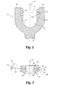
- FIG. 1 is a fragmentary, part-sectional view of a preferred embodiment of the apparatus of the present invention.
- FIG. 2 is a sectional view of part of the receiver member of the embodiment of the apparatus of the present invention illustrated in FIG. 1.
- FIG. 3 is a sectional view of one embodiment of the closure member of the embodiment of the apparatus of the present invention illustrated in FIG. 1.
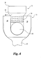
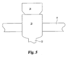
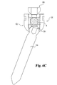
- FIG. 4 is a front elevation of the embodiment of the present invention illustrated in FIG. 1, including an elongated member.
- FIG. 5 is a side elevation of the embodiment of the present invention illustrated in FIG. 4.
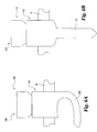
- FIG. 6A is a side elevation of a laminar hook medical device with which an embodiment of the present invention is useful.
- FIG. 6B is a side elevation of one type of bone screw medical device with which an embodiment of the present invention is useful.
- FIG. 6C is a side elevation of one type of multi-axial bone screw medical device with which incorporates an embodiment of the present invention is useful.
- For the purposes of promoting an understanding of the principles of the invention, reference will now be made to the embodiment illustrated in the drawings and specific language will be used to describe the same. It will nevertheless be understood that no limitation of the scope of the invention is thereby intended, such alterations and further modifications in the illustrated device, and such further applications of the principles of the invention as illustrated therein, being contemplated as would normally occur to one skilled in the art to which the invention relates.
- Referring generally to FIGS. 1-5, there is shown a
medical device 10 according to the present invention. As illustrated,medical device 10 includes areceiver member 11 and aclosure member 12 adapted to be threadedly engaged toreceiver member 11.Medical device 10, in the illustrated embodiment, is a bone fixation device used to connect an elongated member (indicated as R in FIGS. 4 - 6C) to a bone. In that embodiment,receiver member 11 includes a longitudinal orthread axis 14, alongitudinal bore 15 centered onaxis 14, and atransverse channel 16 for receiving an elongated member, which is generally perpendicular toaxis 14 and bore 15.Channel 16 is bounded on both sides bylegs 20 ofreceiver member 11.Receiver member 11 further includes afixation portion 22.Fixation portion 22, in a particular embodiment, is a threaded portion for threading into a bone, and in another embodiment is a hook portion for connection to a bone. -
Closure member 12, in a particular embodiment, includes a break-offsection 32 and ascrew section 34. Break-offsection 32 has a generally cylindrical upper orproximal portion 36 and a thinnedneck portion 38. Break-offsection 32 andscrew section 34 haveholes closure member 12 is threadedly engaged withreceiver member 11 to a point at which further threaded progression is impeded, as for example when thescrew section 34 contacts an object withinchannel 16, such as rod R seated againstwall 24. As further torque is applied to break-offscrew closure member 12, as with an hexagonal driving tool inserted intohole 40, eventually the stress on theneck portion 38 is great enough to cause theupper section 36 to break off fromscrew section 34 atneck portion 38. In this way,screw section 34 is firmly seated inbore 15 ofreceiver member 11 against rod R inchannel 16, and the excess material of the break-off screw, which assisted in the original threading, is removed. -
Screw portion 34, and break-offsection 32 included in closure member 12 (as in FIGS. 1, 4 and 5), has a longitudinal axis 43. Whenclosure member 12 andreceiver member 11 are engaged, as illustrated in FIG 1, longitudinal axis 43 ofclosure member 12 andlongitudinal axis 14 ofreceiver member 11 are collinear. -
Receiver member 11 includes aninner thread 44inside legs 20, and screwsection 34 ofclosure member 12 includes anouter thread 46.Threads closure member 12 is threadably engageable withreceiver member 11 by engagingthreads 46 withthread 44.Threads thread 46, illustrated in FIG. 3.Threads - As shown in FIG. 3,
closure member 12 has areverse angle thread 46 including forward-facingthread surface 50 and rearward-facingthread surface 52. Thread 44 (see FIG. 2) has a corresponding forward thread surface 50' and a rearward thread surface 52'.Point 60, depicted in FIG. 3 at the root ofrearward thread surface 52, is closer than point 62 (at the crest of rearward surface 52) to theforward end 64 ofscrew section 34. To define the angles of the thread surfaces,plane 54 normal to longitudinal axis 43 is also shown. As used herein, an angle measured clockwise from a normal plane (such as plane 54) to the rearward thread surface is a negative angle, and an angle measured clockwise from a normal plane (such as plane 54) to the forward thread surface is a positive angle. Thus, pressure angle α of thread 46 (illustrated in FIG. 3) is negative, since the measurement is clockwise from the thread root atplane 54 torearward thread surface 52, as indicated by the arrow. Flank angle β in FIG. 3, representing the clockwise angle fromplane 54 to forwardthread surface 50, is positive. Accordingly, a reverse angle thread includes a rearward surface such that α is a negative angle. - In one particular embodiment of the present invention, illustrated in FIG. 3, pressure angle α is -5 degrees, and flank angle β is 45 degrees. However, it is understood that one of ordinary skill in the art will recognize that other negative values of pressure angle α, including values between about -1 degree and at least -40 degrees, and other values of flank angle β are within the scope of the present invention. As noted above,
reverse angle thread 44 ofreceiver member 11 is configured substantially similarly to reverseangle thread 46 ofclosure member 12 so thatthreads thread 44 forms a negative pressure angle, i.e., one measured clockwise from a plane normal toaxis 14 to rearward thread surface 52', of substantially the same magnitude as pressure angle α illustrated in FIG. 4. Forward thread surface 50' of thread 44 (FIG. 2) forms a positive flank angle of substantially the same magnitude as flank angle β illustrated in FIG. 4. - In use,
closure member 12 is threaded intoreceiver member 11 such thatreverse angle thread 46 ofclosure member 12 is engaged withreverse angle thread 44 ofreceiver member 11. Whenclosure member 12 andreceiver member 11 are threadedly engaged,rearward thread surface 52 ofclosure member 12 will abut rearward thread surface 52' ofreceiver member 11, andforward thread surface 50 ofclosure member 12 will abut forward thread surface 50' ofreceiver member 11. Any force tending to splaylegs 20, such as a force outward from and perpendicular toaxis 14 of FIG. 2, will tend to move rearward thread surface 52' ofreceiver member 11 against and into an interference fit withrearward thread surface 52 ofclosure member 12. The abutment of rearward thread surfaces 52 and 52' prevent splaying oflegs 20 outward fromlongitudinal axis 14 ofreceiver member 11. - It will be appreciated that any medical device which includes a holder or receiver member that tends to splay can incorporate the present invention. As indicated above, in a preferred embodiment of the present invention
medical device 10 is a bone fixation device for connecting an elongated member and a bone, and particularly an "open-back" bone fixation device. Examples of such devices are illustrated in FIGS. 6A - 6C. FIG. 6A illustrates an open-backlaminar hook 100 having an integral U-shapedbone fixation portion 102, and FIG. 6B illustrates an open-back bone screw 110 having an integral threadedbone fixation portion 112.Hook 100 and screw 110 includereceiver members receiver member 11 depicted in FIG. 1, and are thus able to receive rod R in a seated engagement.Hook 100 and screw 110 also includeclosure members closure member 12 of FIG. 1, and thus operate in the same manner as described above with respect to the embodiment of the invention illustrated in FIGS. 1-5. - In the realm of bone fixation devices, the present invention may also be used in connection with a multi-axial bone screw or bone hook system in which the fixation element is rotatable within a body element. One example of such a system is found in U.S. Patent No. 5,797,911 to Sherman, et al., owned by the Assignee of the present invention, an embodiment of which is illustrated in FIG. 6C.
Multi-axial device 120 includes areceiver member 122 similar toreceiver member 11 of FIG. 1, the principal differences being that bone fixation portion 124 (illustrated as a bone screw in FIG. 6C) ofmulti-axial device 120 is not integral withreceiver member 122, and is free to rotate withinbore 126 which extends from top to bottom throughreceiver member 122.Multi-axial device 120 also includes aclosure member 128 which is substantially similar toclosure member 12 of FIG. 1, and thus operates in the same manner as described above with respect to the embodiment of the invention illustrated in FIGS. 1-5. - It is preferred that both
closure member 12 andreceiver member 11 be manufactured from bio-compatible materials, and preferably metals such as titanium or stainless steel. It is also preferred that the reverse angle thread be formed integrally on the outside ofclosure member 12 and on the inside ofreceiver member 11 prior to the use of the medical device. However, forming an integralreverse angle thread 44 on the inside ofreceiver member 11 prior to use is not strictly necessary, so long asclosure member 12 can be twisted intoreceiver member 11 so thatreverse angle thread 46 ofclosure member 12 gouges the insides oflegs 20 to form a threaded engagement betweenclosure member 12 andreceiver member 11. - While the invention has been illustrated and described in detail in the drawings and foregoing description, the same is to be considered as illustrative and not restrictive in character, it being understood that only the preferred embodiment has been shown and described and that all changes and modifications that come within the scope of the invention as defined in the claims are desired to be protected.
Claims (13)
- An orthopedic medical device (10), comprising:a receiver member (11) including a plurality of wall sections defining a longitudinal bore (15) in said medical device (10); anda closure member (12) including a substantially cylindrical engagement portion (34) having a longitudinal axis (43), and a reverse angle thread (46) formed on said engagement portion (34) so that said engagement portion (34) is adapted to be threadedly engaged within said bore (15) to said wall sections,characterised by said receiver member (11) also including a transverse channel (16) substantially perpendicular to said bore (15) and by said closure member (12) being a screw with a break-off section (32).
- The medical device (10) of claim 1, wherein said wall sections include an inner reverse angle thread (44) corresponding to said reverse angle thread (46) of said engagement (34) portion of said closure member (12), whereby said reverse angle thread (44) of said wall sections and said reverse angle thread (46) of said engagement portion (34) are engaged when said engagement portion (34) is threadedly engaged within said bore (15) to said wall sections.
- The medical device (10) of claim 1 or 2, wherein said receiver member (11) is a part of a bone fixation device.
- The medical device (10) of claim 3, wherein said bone fixation device is a bone screw (110).
- The medical device (10) of claim 3 or 4, wherein said bone fixation device is a multi-axial bone screw (120).
- The medical device (10) of claim 3, wherein said bone fixation device is a spinal hook (100).
- The medical device (10) of any of claims 1-6, wherein said reverse angle thread(s) (44, 46) include(s) a rearward thread surface (52', 52), wherein an angle (α) measured from a plane (54) normal with said longitudinal axis (43) to said rearward thread surface (52', 52) is between about -1 degrees and -40 degrees.
- The medical device (10) of claim 7, wherein said angle (α) is about -5 degrees.
- The medical device (10) of claim 1, wherein said longitudinal bore (15) being internally threaded, said channel (16) communicates with said longitudinal bore (15) for accommodating an elongated member (R), said receiver member (11) having a fixation portion (22) for fixing said receiver member (11) to a bone.
- The medical device (10) of claim 2, wherein said channel (16) communicates with said longitudinal bore (15) for accommodating an elongated member (R), said receiver member (11) having a fixation portion (22) for fixing said receiver member (11) to a bone.
- The medical device (10) of claim 9 or 10, wherein said fixation portion (22) is integral with said receiver member (11).
- The medical device (10) of any of claims 9-11 wherein said fixation portion (22) includes a threaded portion.
- The medical device (10) of claim 9 or 10 wherein said bore (15) of said receiver member (11) extends through said receiver member (11), and said fixation portion (124) is a bone fixation device which is accommodated within at least a portion of said bore (15) and is adaptable to be fixed to the bone at any of a plurality of angles to said bore (15).
Priority Applications (1)
| Application Number | Priority Date | Filing Date | Title |
|---|---|---|---|
| EP05076395.2A EP1576931B2 (en) | 1998-11-09 | 1999-11-04 | Medical device having a reverse-angle thread |
Applications Claiming Priority (3)
| Application Number | Priority Date | Filing Date | Title |
|---|---|---|---|
| US09/188,825 US6296642B1 (en) | 1998-11-09 | 1998-11-09 | Reverse angle thread for preventing splaying in medical devices |
| US188825 | 1998-11-09 | ||
| PCT/US1999/025960 WO2000027297A1 (en) | 1998-11-09 | 1999-11-04 | Reverse angle thread for preventing splaying in medical devices |
Related Child Applications (1)
| Application Number | Title | Priority Date | Filing Date |
|---|---|---|---|
| EP05076395.2A Division EP1576931B2 (en) | 1998-11-09 | 1999-11-04 | Medical device having a reverse-angle thread |
Publications (2)
| Publication Number | Publication Date |
|---|---|
| EP1128773A1 EP1128773A1 (en) | 2001-09-05 |
| EP1128773B1 true EP1128773B1 (en) | 2006-06-14 |
Family
ID=22694690
Family Applications (2)
| Application Number | Title | Priority Date | Filing Date |
|---|---|---|---|
| EP99956907A Expired - Lifetime EP1128773B1 (en) | 1998-11-09 | 1999-11-04 | Reverse angle thread for preventing splaying in medical devices |
| EP05076395.2A Expired - Lifetime EP1576931B2 (en) | 1998-11-09 | 1999-11-04 | Medical device having a reverse-angle thread |
Family Applications After (1)
| Application Number | Title | Priority Date | Filing Date |
|---|---|---|---|
| EP05076395.2A Expired - Lifetime EP1576931B2 (en) | 1998-11-09 | 1999-11-04 | Medical device having a reverse-angle thread |
Country Status (9)
| Country | Link |
|---|---|
| US (1) | US6296642B1 (en) |
| EP (2) | EP1128773B1 (en) |
| JP (1) | JP2002529136A (en) |
| AT (2) | ATE329539T1 (en) |
| AU (1) | AU760881B2 (en) |
| CA (1) | CA2349849C (en) |
| DE (2) | DE69941016D1 (en) |
| ES (1) | ES2276539T3 (en) |
| WO (1) | WO2000027297A1 (en) |
Cited By (5)
| Publication number | Priority date | Publication date | Assignee | Title |
|---|---|---|---|---|
| US8096996B2 (en) | 2007-03-20 | 2012-01-17 | Exactech, Inc. | Rod reducer |
| US8226690B2 (en) | 2005-07-22 | 2012-07-24 | The Board Of Trustees Of The Leland Stanford Junior University | Systems and methods for stabilization of bone structures |
| US8267969B2 (en) | 2004-10-20 | 2012-09-18 | Exactech, Inc. | Screw systems and methods for use in stabilization of bone structures |
| US8523865B2 (en) | 2005-07-22 | 2013-09-03 | Exactech, Inc. | Tissue splitter |
| CN104783887A (en) * | 2015-05-06 | 2015-07-22 | 山东威高骨科材料股份有限公司 | High-strength bone screw base |
Families Citing this family (220)
| Publication number | Priority date | Publication date | Assignee | Title |
|---|---|---|---|---|
| US7695502B2 (en) * | 2000-02-01 | 2010-04-13 | Depuy Products, Inc. | Bone stabilization system including plate having fixed-angle holes together with unidirectional locking screws and surgeon-directed locking screws |
| US20050267477A1 (en) * | 2000-06-06 | 2005-12-01 | Jackson Roger P | Removable medical implant closure |
| US20050187549A1 (en) * | 2000-06-06 | 2005-08-25 | Jackson Roger P. | Removable medical implant closure |
| FR2810874B1 (en) * | 2000-06-30 | 2002-08-23 | Materiel Orthopedique En Abreg | IMPLANT FOR OSTEOSYNTHESIS DEVICE COMPRISING A PART FOR BONE ANCHORING AND A BODY FOR FIXING ON A ROD |
| US7056321B2 (en) | 2000-08-01 | 2006-06-06 | Endius, Incorporated | Method of securing vertebrae |
| US7985247B2 (en) | 2000-08-01 | 2011-07-26 | Zimmer Spine, Inc. | Methods and apparatuses for treating the spine through an access device |
| US7833250B2 (en) | 2004-11-10 | 2010-11-16 | Jackson Roger P | Polyaxial bone screw with helically wound capture connection |
| US20060083603A1 (en) * | 2000-08-23 | 2006-04-20 | Jackson Roger P | Reverse angled threadform with anti-splay clearance |
| US7837716B2 (en) * | 2000-08-23 | 2010-11-23 | Jackson Roger P | Threadform for medical implant closure |
| US20060025771A1 (en) | 2000-08-23 | 2006-02-02 | Jackson Roger P | Helical reverse angle guide and advancement structure with break-off extensions |
| US6485491B1 (en) * | 2000-09-15 | 2002-11-26 | Sdgi Holdings, Inc. | Posterior fixation system |
| US8512380B2 (en) | 2002-08-28 | 2013-08-20 | Warsaw Orthopedic, Inc. | Posterior fixation system |
| ES2240384T3 (en) * | 2000-09-18 | 2005-10-16 | Zimmer Gmbh | PEDICULAR SCREW FOR INTERVERTEBRAL SUPPORT ELEMENT. |
| EP1188416B1 (en) * | 2000-09-18 | 2005-06-01 | Zimmer GmbH | Pedicle screw for intervertebral support element |
| US6755829B1 (en) * | 2000-09-22 | 2004-06-29 | Depuy Acromed, Inc. | Lock cap anchor assembly for orthopaedic fixation |
| DE10055888C1 (en) | 2000-11-10 | 2002-04-25 | Biedermann Motech Gmbh | Bone screw, has connector rod receiving part with unsymmetrically arranged end bores |
| US6726689B2 (en) | 2002-09-06 | 2004-04-27 | Roger P. Jackson | Helical interlocking mating guide and advancement structure |
| US6997927B2 (en) * | 2000-12-08 | 2006-02-14 | Jackson Roger P | closure for rod receiving orthopedic implant having a pair of spaced apertures for removal |
| US8377100B2 (en) | 2000-12-08 | 2013-02-19 | Roger P. Jackson | Closure for open-headed medical implant |
| DE50100793D1 (en) * | 2000-12-27 | 2003-11-20 | Biedermann Motech Gmbh | Screw for connecting to a rod |
| US8518090B2 (en) | 2010-10-05 | 2013-08-27 | Acumed Llc | Fastener with serrated thread for attachment to a bone plate at a selectable angle |
| US10258382B2 (en) | 2007-01-18 | 2019-04-16 | Roger P. Jackson | Rod-cord dynamic connection assemblies with slidable bone anchor attachment members along the cord |
| US8292926B2 (en) | 2005-09-30 | 2012-10-23 | Jackson Roger P | Dynamic stabilization connecting member with elastic core and outer sleeve |
| US8353932B2 (en) | 2005-09-30 | 2013-01-15 | Jackson Roger P | Polyaxial bone anchor assembly with one-piece closure, pressure insert and plastic elongate member |
| US7862587B2 (en) | 2004-02-27 | 2011-01-04 | Jackson Roger P | Dynamic stabilization assemblies, tool set and method |
| US10729469B2 (en) | 2006-01-09 | 2020-08-04 | Roger P. Jackson | Flexible spinal stabilization assembly with spacer having off-axis core member |
| JP4181035B2 (en) * | 2001-07-19 | 2008-11-12 | アビザ ヨーロッパ リミティド | Tantalum film deposition |
| CH695478A5 (en) * | 2001-07-20 | 2006-06-15 | Werner Hermann | Threaded bolt, and Pedrikelschraube Pedrikelschraube with threaded bolt |
| DE10157969C1 (en) | 2001-11-27 | 2003-02-06 | Biedermann Motech Gmbh | Element used in spinal and accident surgery comprises a shaft joined to a holding element having a U-shaped recess with two free arms having an internal thread with flanks lying at right angles to the central axis of the holding element |
| US7658582B2 (en) * | 2003-07-09 | 2010-02-09 | Ortho Innovations, Llc | Precise linear fastener system and method for use |
| US7879075B2 (en) * | 2002-02-13 | 2011-02-01 | Zimmer Spine, Inc. | Methods for connecting a longitudinal member to a bone portion |
| US7066937B2 (en) * | 2002-02-13 | 2006-06-27 | Endius Incorporated | Apparatus for connecting a longitudinal member to a bone portion |
| US6740086B2 (en) | 2002-04-18 | 2004-05-25 | Spinal Innovations, Llc | Screw and rod fixation assembly and device |
| US11224464B2 (en) | 2002-05-09 | 2022-01-18 | Roger P. Jackson | Threaded closure with inwardly-facing tool engaging concave radiused structures and axial through-aperture |
| US20040167525A1 (en) * | 2002-09-06 | 2004-08-26 | Jackson Roger P. | Anti-splay medical implant closure with multi-stepped removal counterbore |
| US8876868B2 (en) * | 2002-09-06 | 2014-11-04 | Roger P. Jackson | Helical guide and advancement flange with radially loaded lip |
| US20040167524A1 (en) * | 2002-09-06 | 2004-08-26 | Jackson Roger P. | Anti-splay medical implant closure with central multi-surface insertion and removal aperture |
| US8282673B2 (en) * | 2002-09-06 | 2012-10-09 | Jackson Roger P | Anti-splay medical implant closure with multi-surface removal aperture |
| US8257402B2 (en) | 2002-09-06 | 2012-09-04 | Jackson Roger P | Closure for rod receiving orthopedic implant having left handed thread removal |
| DE10256095B4 (en) * | 2002-12-02 | 2004-11-18 | Biedermann Motech Gmbh | Element with a shaft and an associated holding element for connecting to a rod |
| US7780664B2 (en) | 2002-12-10 | 2010-08-24 | Depuy Products, Inc. | Endosteal nail |
| US20040162560A1 (en) * | 2003-02-19 | 2004-08-19 | Raynor Donald E. | Implant device including threaded locking mechanism |
| US20040186473A1 (en) * | 2003-03-21 | 2004-09-23 | Cournoyer John R. | Spinal fixation devices of improved strength and rigidity |
| US8540753B2 (en) * | 2003-04-09 | 2013-09-24 | Roger P. Jackson | Polyaxial bone screw with uploaded threaded shank and method of assembly and use |
| US6716214B1 (en) | 2003-06-18 | 2004-04-06 | Roger P. Jackson | Polyaxial bone screw with spline capture connection |
| US7621918B2 (en) | 2004-11-23 | 2009-11-24 | Jackson Roger P | Spinal fixation tool set and method |
| US20050177164A1 (en) * | 2003-05-02 | 2005-08-11 | Carmen Walters | Pedicle screw devices, systems and methods having a preloaded set screw |
| US7615068B2 (en) * | 2003-05-02 | 2009-11-10 | Applied Spine Technologies, Inc. | Mounting mechanisms for pedicle screws and related assemblies |
| US20050182401A1 (en) * | 2003-05-02 | 2005-08-18 | Timm Jens P. | Systems and methods for spine stabilization including a dynamic junction |
| US7635379B2 (en) * | 2003-05-02 | 2009-12-22 | Applied Spine Technologies, Inc. | Pedicle screw assembly with bearing surfaces |
| US7377923B2 (en) | 2003-05-22 | 2008-05-27 | Alphatec Spine, Inc. | Variable angle spinal screw assembly |
| US8092500B2 (en) | 2007-05-01 | 2012-01-10 | Jackson Roger P | Dynamic stabilization connecting member with floating core, compression spacer and over-mold |
| US8926670B2 (en) | 2003-06-18 | 2015-01-06 | Roger P. Jackson | Polyaxial bone screw assembly |
| US8137386B2 (en) * | 2003-08-28 | 2012-03-20 | Jackson Roger P | Polyaxial bone screw apparatus |
| US8377102B2 (en) | 2003-06-18 | 2013-02-19 | Roger P. Jackson | Polyaxial bone anchor with spline capture connection and lower pressure insert |
| US7967850B2 (en) | 2003-06-18 | 2011-06-28 | Jackson Roger P | Polyaxial bone anchor with helical capture connection, insert and dual locking assembly |
| US8366753B2 (en) | 2003-06-18 | 2013-02-05 | Jackson Roger P | Polyaxial bone screw assembly with fixed retaining structure |
| US7776067B2 (en) | 2005-05-27 | 2010-08-17 | Jackson Roger P | Polyaxial bone screw with shank articulation pressure insert and method |
| US7204838B2 (en) * | 2004-12-20 | 2007-04-17 | Jackson Roger P | Medical implant fastener with nested set screw and method |
| US7766915B2 (en) | 2004-02-27 | 2010-08-03 | Jackson Roger P | Dynamic fixation assemblies with inner core and outer coil-like member |
| US8398682B2 (en) | 2003-06-18 | 2013-03-19 | Roger P. Jackson | Polyaxial bone screw assembly |
| US8257398B2 (en) | 2003-06-18 | 2012-09-04 | Jackson Roger P | Polyaxial bone screw with cam capture |
| US20040260284A1 (en) * | 2003-06-23 | 2004-12-23 | Matthew Parker | Anti-splay pedicle screw |
| US7087057B2 (en) | 2003-06-27 | 2006-08-08 | Depuy Acromed, Inc. | Polyaxial bone screw |
| US7967826B2 (en) | 2003-10-21 | 2011-06-28 | Theken Spine, Llc | Connector transfer tool for internal structure stabilization systems |
| US7588588B2 (en) | 2003-10-21 | 2009-09-15 | Innovative Spinal Technologies | System and method for stabilizing of internal structures |
| US7905907B2 (en) | 2003-10-21 | 2011-03-15 | Theken Spine, Llc | Internal structure stabilization system for spanning three or more structures |
| US11419642B2 (en) | 2003-12-16 | 2022-08-23 | Medos International Sarl | Percutaneous access devices and bone anchor assemblies |
| US7179261B2 (en) | 2003-12-16 | 2007-02-20 | Depuy Spine, Inc. | Percutaneous access devices and bone anchor assemblies |
| US7527638B2 (en) | 2003-12-16 | 2009-05-05 | Depuy Spine, Inc. | Methods and devices for minimally invasive spinal fixation element placement |
| US7789896B2 (en) * | 2005-02-22 | 2010-09-07 | Jackson Roger P | Polyaxial bone screw assembly |
| JP2007525274A (en) | 2004-02-27 | 2007-09-06 | ロジャー・ピー・ジャクソン | Orthopedic implant rod reduction instrument set and method |
| US8152810B2 (en) | 2004-11-23 | 2012-04-10 | Jackson Roger P | Spinal fixation tool set and method |
| US7160300B2 (en) | 2004-02-27 | 2007-01-09 | Jackson Roger P | Orthopedic implant rod reduction tool set and method |
| US11241261B2 (en) | 2005-09-30 | 2022-02-08 | Roger P Jackson | Apparatus and method for soft spinal stabilization using a tensionable cord and releasable end structure |
| DE102004010380A1 (en) * | 2004-03-03 | 2005-09-22 | Biedermann Motech Gmbh | Anchoring element and stabilizing device for the dynamic stabilization of vertebrae or bones with such an anchoring element |
| US7214227B2 (en) * | 2004-03-22 | 2007-05-08 | Innovative Spinal Technologies | Closure member for a medical implant device |
| US7503924B2 (en) | 2004-04-08 | 2009-03-17 | Globus Medical, Inc. | Polyaxial screw |
| US8475495B2 (en) | 2004-04-08 | 2013-07-02 | Globus Medical | Polyaxial screw |
| WO2005102195A1 (en) | 2004-04-20 | 2005-11-03 | Allez Spine, Llc | Pedicle screw assembly |
| US7763049B2 (en) * | 2004-06-09 | 2010-07-27 | Zimmer Spine, Inc. | Orthopedic fixation connector |
| US7264621B2 (en) * | 2004-06-17 | 2007-09-04 | Sdgi Holdings, Inc. | Multi-axial bone attachment assembly |
| US7651502B2 (en) | 2004-09-24 | 2010-01-26 | Jackson Roger P | Spinal fixation tool set and method for rod reduction and fastener insertion |
| US8926672B2 (en) | 2004-11-10 | 2015-01-06 | Roger P. Jackson | Splay control closure for open bone anchor |
| JP2008519656A (en) * | 2004-11-10 | 2008-06-12 | ロジャー・ピー・ジャクソン | Helical guide and forward flange with break extension |
| US7569061B2 (en) | 2004-11-16 | 2009-08-04 | Innovative Spinal Technologies, Inc. | Off-axis anchor guidance system |
| WO2006057837A1 (en) | 2004-11-23 | 2006-06-01 | Jackson Roger P | Spinal fixation tool attachment structure |
| US8308782B2 (en) | 2004-11-23 | 2012-11-13 | Jackson Roger P | Bone anchors with longitudinal connecting member engaging inserts and closures for fixation and optional angulation |
| US7875065B2 (en) * | 2004-11-23 | 2011-01-25 | Jackson Roger P | Polyaxial bone screw with multi-part shank retainer and pressure insert |
| US9168069B2 (en) | 2009-06-15 | 2015-10-27 | Roger P. Jackson | Polyaxial bone anchor with pop-on shank and winged insert with lower skirt for engaging a friction fit retainer |
| US9216041B2 (en) | 2009-06-15 | 2015-12-22 | Roger P. Jackson | Spinal connecting members with tensioned cords and rigid sleeves for engaging compression inserts |
| US8444681B2 (en) | 2009-06-15 | 2013-05-21 | Roger P. Jackson | Polyaxial bone anchor with pop-on shank, friction fit retainer and winged insert |
| US9980753B2 (en) | 2009-06-15 | 2018-05-29 | Roger P Jackson | pivotal anchor with snap-in-place insert having rotation blocking extensions |
| WO2006058221A2 (en) | 2004-11-24 | 2006-06-01 | Abdou Samy M | Devices and methods for inter-vertebral orthopedic device placement |
| US10076361B2 (en) | 2005-02-22 | 2018-09-18 | Roger P. Jackson | Polyaxial bone screw with spherical capture, compression and alignment and retention structures |
| US7901437B2 (en) | 2007-01-26 | 2011-03-08 | Jackson Roger P | Dynamic stabilization member with molded connection |
| US7708762B2 (en) * | 2005-04-08 | 2010-05-04 | Warsaw Orthopedic, Inc. | Systems, devices and methods for stabilization of the spinal column |
| US7794481B2 (en) * | 2005-04-22 | 2010-09-14 | Warsaw Orthopedic, Inc. | Force limiting coupling assemblies for spinal implants |
| JP4903787B2 (en) * | 2005-04-25 | 2012-03-28 | ジンテス ゲゼルシャフト ミット ベシュレンクテル ハフツング | Bone anchor with locking cap and bone fixation method |
| EP1726264B1 (en) | 2005-05-27 | 2009-05-20 | BIEDERMANN MOTECH GmbH | Receiving part for connecting a shank of a bone anchoring element to a rod and bone anchoring device with such a receiving part |
| US7766946B2 (en) | 2005-07-27 | 2010-08-03 | Frank Emile Bailly | Device for securing spinal rods |
| US7625394B2 (en) * | 2005-08-05 | 2009-12-01 | Warsaw Orthopedic, Inc. | Coupling assemblies for spinal implants |
| US7905909B2 (en) | 2005-09-19 | 2011-03-15 | Depuy Products, Inc. | Bone stabilization system including multi-directional threaded fixation element |
| US7955358B2 (en) | 2005-09-19 | 2011-06-07 | Albert Todd J | Bone screw apparatus, system and method |
| US8105368B2 (en) | 2005-09-30 | 2012-01-31 | Jackson Roger P | Dynamic stabilization connecting member with slitted core and outer sleeve |
| US8075599B2 (en) | 2005-10-18 | 2011-12-13 | Warsaw Orthopedic, Inc. | Adjustable bone anchor assembly |
| US20070118117A1 (en) * | 2005-10-20 | 2007-05-24 | Ebi, L.P. | Bone fixation assembly |
| US8100946B2 (en) * | 2005-11-21 | 2012-01-24 | Synthes Usa, Llc | Polyaxial bone anchors with increased angulation |
| US7704271B2 (en) | 2005-12-19 | 2010-04-27 | Abdou M Samy | Devices and methods for inter-vertebral orthopedic device placement |
| US8740947B2 (en) * | 2006-02-15 | 2014-06-03 | Warsaw, Orthopedic, Inc. | Multiple lead bone fixation apparatus |
| US7641674B2 (en) * | 2006-03-01 | 2010-01-05 | Warsaw Orthopedic, Inc. | Devices for securing elongated spinal connecting elements in bone anchors |
| WO2007114834A1 (en) | 2006-04-05 | 2007-10-11 | Dong Myung Jeon | Multi-axial, double locking bone screw assembly |
| US20070253792A1 (en) * | 2006-04-27 | 2007-11-01 | Homac Mfg. Company | Torque limiting break-away head fastener and related methods |
| US20070270831A1 (en) * | 2006-05-01 | 2007-11-22 | Sdgi Holdings, Inc. | Bone anchor system utilizing a molded coupling member for coupling a bone anchor to a stabilization member and method therefor |
| US20070270832A1 (en) * | 2006-05-01 | 2007-11-22 | Sdgi Holdings, Inc. | Locking device and method, for use in a bone stabilization system, employing a set screw member and deformable saddle member |
| US7914559B2 (en) * | 2006-05-30 | 2011-03-29 | Warsaw Orthopedic, Inc. | Locking device and method employing a posted member to control positioning of a stabilization member of a bone stabilization system |
| US20070288003A1 (en) * | 2006-05-30 | 2007-12-13 | Dewey Jonathan M | Locking device and method, for use in a bone stabilization system, employing a break-away interface member rigidly coupled to a seating member |
| US20080015601A1 (en) * | 2006-06-14 | 2008-01-17 | Michael Castro | Reduction device and method of use |
| WO2008008511A2 (en) | 2006-07-14 | 2008-01-17 | Laszlo Garamszegi | Pedicle screw assembly with inclined surface seat |
| US7918858B2 (en) | 2006-09-26 | 2011-04-05 | Depuy Spine, Inc. | Minimally invasive bone anchor extensions |
| WO2008073323A2 (en) | 2006-12-08 | 2008-06-19 | Jackson Roger P | Tool system for dynamic spinal implants |
| US8747445B2 (en) | 2007-01-15 | 2014-06-10 | Ebi, Llc | Spinal fixation device |
| US8475498B2 (en) | 2007-01-18 | 2013-07-02 | Roger P. Jackson | Dynamic stabilization connecting member with cord connection |
| US8366745B2 (en) | 2007-05-01 | 2013-02-05 | Jackson Roger P | Dynamic stabilization assembly having pre-compressed spacers with differential displacements |
| US7931676B2 (en) | 2007-01-18 | 2011-04-26 | Warsaw Orthopedic, Inc. | Vertebral stabilizer |
| US10792074B2 (en) | 2007-01-22 | 2020-10-06 | Roger P. Jackson | Pivotal bone anchor assemly with twist-in-place friction fit insert |
| US8012177B2 (en) | 2007-02-12 | 2011-09-06 | Jackson Roger P | Dynamic stabilization assembly with frusto-conical connection |
| US7967849B2 (en) * | 2007-04-06 | 2011-06-28 | Warsaw Orthopedic, Inc. | Adjustable multi-axial spinal coupling assemblies |
| US7922725B2 (en) | 2007-04-19 | 2011-04-12 | Zimmer Spine, Inc. | Method and associated instrumentation for installation of spinal dynamic stabilization system |
| US10383660B2 (en) | 2007-05-01 | 2019-08-20 | Roger P. Jackson | Soft stabilization assemblies with pretensioned cords |
| US7947065B2 (en) | 2008-11-14 | 2011-05-24 | Ortho Innovations, Llc | Locking polyaxial ball and socket fastener |
| US7942911B2 (en) * | 2007-05-16 | 2011-05-17 | Ortho Innovations, Llc | Polyaxial bone screw |
| US7942910B2 (en) * | 2007-05-16 | 2011-05-17 | Ortho Innovations, Llc | Polyaxial bone screw |
| US7942909B2 (en) * | 2009-08-13 | 2011-05-17 | Ortho Innovations, Llc | Thread-thru polyaxial pedicle screw system |
| US7951173B2 (en) | 2007-05-16 | 2011-05-31 | Ortho Innovations, Llc | Pedicle screw implant system |
| US8197518B2 (en) | 2007-05-16 | 2012-06-12 | Ortho Innovations, Llc | Thread-thru polyaxial pedicle screw system |
| AU2008263148C1 (en) | 2007-05-31 | 2012-05-24 | Roger P. Jackson | Dynamic stabilization connecting member with pre-tensioned solid core |
| US9439681B2 (en) | 2007-07-20 | 2016-09-13 | DePuy Synthes Products, Inc. | Polyaxial bone fixation element |
| US8414588B2 (en) | 2007-10-04 | 2013-04-09 | Depuy Spine, Inc. | Methods and devices for minimally invasive spinal connection element delivery |
| US8911477B2 (en) | 2007-10-23 | 2014-12-16 | Roger P. Jackson | Dynamic stabilization member with end plate support and cable core extension |
| US8007522B2 (en) | 2008-02-04 | 2011-08-30 | Depuy Spine, Inc. | Methods for correction of spinal deformities |
| US9277940B2 (en) | 2008-02-05 | 2016-03-08 | Zimmer Spine, Inc. | System and method for insertion of flexible spinal stabilization element |
| US20090292308A1 (en) * | 2008-05-22 | 2009-11-26 | K2M, Inc. | Spinal fixation system |
| JP2012529969A (en) | 2008-08-01 | 2012-11-29 | ロジャー・ピー・ジャクソン | Longitudinal connecting member with tensioning cord with sleeve |
| JP5815407B2 (en) | 2008-09-12 | 2015-11-17 | ジンテス ゲゼルシャフト ミット ベシュレンクテル ハフツング | Spinal stabilization and guided fixation system |
| WO2010037098A1 (en) | 2008-09-29 | 2010-04-01 | Synthes Usa, Llc | Polyaxial bottom-loading screw and rod assembly |
| US8506601B2 (en) | 2008-10-14 | 2013-08-13 | Pioneer Surgical Technology, Inc. | Low profile dual locking fixation system and offset anchor member |
| US8382809B2 (en) * | 2008-10-17 | 2013-02-26 | Omni Surgical | Poly-axial pedicle screw implements and lock screw therefor |
| EP2376005B1 (en) | 2008-11-03 | 2016-05-18 | Synthes GmbH | Uni-planar bone fixation assembly |
| US8696717B2 (en) * | 2008-11-05 | 2014-04-15 | K2M, Inc. | Multi-planar, taper lock screw with additional lock |
| US8377101B2 (en) * | 2008-11-05 | 2013-02-19 | K2M, Inc. | Multi-planar taper lock screw with increased rod friction |
| US8075603B2 (en) | 2008-11-14 | 2011-12-13 | Ortho Innovations, Llc | Locking polyaxial ball and socket fastener |
| ES2352720B1 (en) * | 2009-01-26 | 2011-12-30 | Surgival Co., S.A. | PRESSURE SCREW AND AUTOBLOCATING TULIP FIXING DEVICE. |
| US8636778B2 (en) | 2009-02-11 | 2014-01-28 | Pioneer Surgical Technology, Inc. | Wide angulation coupling members for bone fixation system |
| CN102368967B (en) | 2009-04-15 | 2016-03-02 | 斯恩蒂斯有限公司 | For the revision connector of spinal structure |
| US11229457B2 (en) | 2009-06-15 | 2022-01-25 | Roger P. Jackson | Pivotal bone anchor assembly with insert tool deployment |
| CN103826560A (en) | 2009-06-15 | 2014-05-28 | 罗杰.P.杰克逊 | Polyaxial bone anchor with pop-on shank and winged insert with friction fit compressive collet |
| US9668771B2 (en) | 2009-06-15 | 2017-06-06 | Roger P Jackson | Soft stabilization assemblies with off-set connector |
| US8998959B2 (en) | 2009-06-15 | 2015-04-07 | Roger P Jackson | Polyaxial bone anchors with pop-on shank, fully constrained friction fit retainer and lock and release insert |
| EP2753252A1 (en) | 2009-06-15 | 2014-07-16 | Jackson, Roger P. | Polyaxial bone anchor with pop-on shank and friction fit retainer with low profile edge lock |
| WO2010148231A1 (en) | 2009-06-17 | 2010-12-23 | Synthes Usa, Llc | Revision connector for spinal constructs |
| CA2774471A1 (en) | 2009-10-05 | 2011-04-14 | James L. Surber | Polyaxial bone anchor with non-pivotable retainer and pop-on shank, some with friction fit |
| US20110106179A1 (en) * | 2009-10-30 | 2011-05-05 | Warsaw Orthopedic, Inc. | Set Screw Having Variable Pitch Thread for Use With Spinal Implant Systems |
| US9044272B2 (en) | 2009-11-09 | 2015-06-02 | Ebi, Llc | Multiplanar bone anchor system |
| US8764806B2 (en) | 2009-12-07 | 2014-07-01 | Samy Abdou | Devices and methods for minimally invasive spinal stabilization and instrumentation |
| US9393049B2 (en) | 2010-08-20 | 2016-07-19 | K2M, Inc. | Spinal fixation system |
| WO2012030712A1 (en) | 2010-08-30 | 2012-03-08 | Zimmer Spine, Inc. | Polyaxial pedicle screw |
| AU2011299558A1 (en) | 2010-09-08 | 2013-05-02 | Roger P. Jackson | Dynamic stabilization members with elastic and inelastic sections |
| DE112011103644T5 (en) | 2010-11-02 | 2013-12-24 | Roger P. Jackson | Polyaxial bone anchor with quick-release shaft and rotatable holder |
| US8523915B2 (en) * | 2010-12-09 | 2013-09-03 | Warsaw Orthopedic, Inc. | Friction set screw for use with spinal implant systems |
| US20120214127A1 (en) * | 2011-02-22 | 2012-08-23 | Warsaw Orthopedic, Inc. | Dental implant system with separable drive and method |
| WO2012128825A1 (en) | 2011-03-24 | 2012-09-27 | Jackson Roger P | Polyaxial bone anchor with compound articulation and pop-on shank |
| US9186187B2 (en) | 2011-07-15 | 2015-11-17 | Globus Medical, Inc. | Orthopedic fixation devices and methods of installation thereof |
| US9358047B2 (en) | 2011-07-15 | 2016-06-07 | Globus Medical, Inc. | Orthopedic fixation devices and methods of installation thereof |
| US8888827B2 (en) | 2011-07-15 | 2014-11-18 | Globus Medical, Inc. | Orthopedic fixation devices and methods of installation thereof |
| US9993269B2 (en) | 2011-07-15 | 2018-06-12 | Globus Medical, Inc. | Orthopedic fixation devices and methods of installation thereof |
| US9198694B2 (en) | 2011-07-15 | 2015-12-01 | Globus Medical, Inc. | Orthopedic fixation devices and methods of installation thereof |
| US8845728B1 (en) | 2011-09-23 | 2014-09-30 | Samy Abdou | Spinal fixation devices and methods of use |
| US8956361B2 (en) | 2011-12-19 | 2015-02-17 | Amendia, Inc. | Extended tab bone screw system |
| US8911479B2 (en) | 2012-01-10 | 2014-12-16 | Roger P. Jackson | Multi-start closures for open implants |
| US20130226240A1 (en) | 2012-02-22 | 2013-08-29 | Samy Abdou | Spinous process fixation devices and methods of use |
| US20130218213A1 (en) * | 2012-02-22 | 2013-08-22 | Zimmer Spine, Inc. | Bone screw including a dual thread closure member |
| AU2013259052B2 (en) | 2012-05-11 | 2017-09-14 | Orthopediatrics Corp. | Surgical connectors and instrumentation |
| US9198767B2 (en) | 2012-08-28 | 2015-12-01 | Samy Abdou | Devices and methods for spinal stabilization and instrumentation |
| US9782204B2 (en) | 2012-09-28 | 2017-10-10 | Medos International Sarl | Bone anchor assemblies |
| US9320617B2 (en) | 2012-10-22 | 2016-04-26 | Cogent Spine, LLC | Devices and methods for spinal stabilization and instrumentation |
| US8911478B2 (en) | 2012-11-21 | 2014-12-16 | Roger P. Jackson | Splay control closure for open bone anchor |
| US10058354B2 (en) | 2013-01-28 | 2018-08-28 | Roger P. Jackson | Pivotal bone anchor assembly with frictional shank head seating surfaces |
| US8852239B2 (en) | 2013-02-15 | 2014-10-07 | Roger P Jackson | Sagittal angle screw with integral shank and receiver |
| US9103367B2 (en) | 2013-03-14 | 2015-08-11 | Imds Llc | Polyaxial locking interface |
| US10342582B2 (en) | 2013-03-14 | 2019-07-09 | DePuy Synthes Products, Inc. | Bone anchor assemblies and methods with improved locking |
| US20140277153A1 (en) | 2013-03-14 | 2014-09-18 | DePuy Synthes Products, LLC | Bone Anchor Assemblies and Methods With Improved Locking |
| US9724145B2 (en) | 2013-03-14 | 2017-08-08 | Medos International Sarl | Bone anchor assemblies with multiple component bottom loading bone anchors |
| US9404525B2 (en) | 2013-03-14 | 2016-08-02 | Imds Llc | Polyaxial locking interface |
| US9259247B2 (en) | 2013-03-14 | 2016-02-16 | Medos International Sarl | Locking compression members for use with bone anchor assemblies and methods |
| US20140277155A1 (en) | 2013-03-14 | 2014-09-18 | K2M, Inc. | Taper lock hook |
| US9775660B2 (en) | 2013-03-14 | 2017-10-03 | DePuy Synthes Products, Inc. | Bottom-loading bone anchor assemblies and methods |
| US10292832B2 (en) | 2013-03-14 | 2019-05-21 | Ohio State Innovation Foundation | Spinal fixation device |
| US9707096B2 (en) | 2013-03-14 | 2017-07-18 | K2M, Inc. | Spinal fixation device |
| US9453526B2 (en) | 2013-04-30 | 2016-09-27 | Degen Medical, Inc. | Bottom-loading anchor assembly |
| US9566092B2 (en) | 2013-10-29 | 2017-02-14 | Roger P. Jackson | Cervical bone anchor with collet retainer and outer locking sleeve |
| US9717533B2 (en) | 2013-12-12 | 2017-08-01 | Roger P. Jackson | Bone anchor closure pivot-splay control flange form guide and advancement structure |
| US9451993B2 (en) | 2014-01-09 | 2016-09-27 | Roger P. Jackson | Bi-radial pop-on cervical bone anchor |
| US9597119B2 (en) | 2014-06-04 | 2017-03-21 | Roger P. Jackson | Polyaxial bone anchor with polymer sleeve |
| US10064658B2 (en) | 2014-06-04 | 2018-09-04 | Roger P. Jackson | Polyaxial bone anchor with insert guides |
| EP3303856B1 (en) | 2015-06-02 | 2022-03-02 | Volvo Truck Corporation | Thread for an air-dryer cartridge |
| AU2016324333B2 (en) | 2015-09-18 | 2021-03-18 | K2M, Inc. | Corpectomy device and method of use thereof |
| US10857003B1 (en) | 2015-10-14 | 2020-12-08 | Samy Abdou | Devices and methods for vertebral stabilization |
| US10973648B1 (en) | 2016-10-25 | 2021-04-13 | Samy Abdou | Devices and methods for vertebral bone realignment |
| US10744000B1 (en) | 2016-10-25 | 2020-08-18 | Samy Abdou | Devices and methods for vertebral bone realignment |
| US11389205B2 (en) | 2016-11-30 | 2022-07-19 | Stryker European Operations Holdings Llc | Spinal fastener with serrated thread |
| US10966758B2 (en) | 2017-05-03 | 2021-04-06 | Advance Research System, Llc | Reinforcement caps for spinal support systems |
| US11648037B2 (en) | 2017-05-03 | 2023-05-16 | Advance Research System, Llc | Extension-ready spinal support system with vascular-safe pedicle screw |
| USD898196S1 (en) | 2017-07-10 | 2020-10-06 | Stryker European Holdings I, Llc | Spinal fastener with serrated thread |
| US11540863B2 (en) | 2018-07-31 | 2023-01-03 | GetSet Surgical SA | Spinal surgery systems and methods |
| US11179248B2 (en) | 2018-10-02 | 2021-11-23 | Samy Abdou | Devices and methods for spinal implantation |
| USD927687S1 (en) | 2019-06-07 | 2021-08-10 | GetSet Surgical SA | Surgical instrument handle |
| USD926312S1 (en) | 2019-06-07 | 2021-07-27 | GetSet Surgical SA | Surgical instrument handle |
| USD896384S1 (en) | 2019-06-07 | 2020-09-15 | GetSet Surgical SA | Spinal fusion cage |
| USD926978S1 (en) | 2019-06-07 | 2021-08-03 | GetSet Surgical SA | Surgical instrument handle |
Citations (2)
| Publication number | Priority date | Publication date | Assignee | Title |
|---|---|---|---|---|
| US5005562A (en) * | 1988-06-24 | 1991-04-09 | Societe De Fabrication De Material Orthopedique | Implant for spinal osteosynthesis device, in particular in traumatology |
| US5728098A (en) * | 1996-11-07 | 1998-03-17 | Sdgi Holdings, Inc. | Multi-angle bone screw assembly using shape-memory technology |
Family Cites Families (44)
| Publication number | Priority date | Publication date | Assignee | Title |
|---|---|---|---|---|
| US3640416A (en) * | 1970-10-16 | 1972-02-08 | John J Temple | Reverse angle thread system for containers |
| GB1551706A (en) | 1975-04-28 | 1979-08-30 | Downs Surgical Ltd | Surgical implant |
| US4653486A (en) * | 1984-04-12 | 1987-03-31 | Coker Tom P | Fastener, particularly suited for orthopedic use |
| FR2589092B1 (en) † | 1985-10-28 | 1987-11-13 | Escofier Tech Sa | METHOD OF FORMING HELICOID NETS WITH NULL OR NEGATIVE TILT SIDE |
| US4707001A (en) * | 1986-06-20 | 1987-11-17 | Seal-Tech, Inc. | Liner connection |
| US5468241A (en) | 1988-02-18 | 1995-11-21 | Howmedica Gmbh | Support device for the human vertebral column |
| US4950269A (en) | 1988-06-13 | 1990-08-21 | Acromed Corporation | Spinal column fixation device |
| DE3942326A1 (en) | 1989-12-21 | 1991-06-27 | Haerle Anton | SCREW AS AN OSTEOSYNTHESIS TOOL |
| GB9007519D0 (en) * | 1990-04-03 | 1990-05-30 | Trisport Ltd | Studded footwear |
| US5360431A (en) | 1990-04-26 | 1994-11-01 | Cross Medical Products | Transpedicular screw system and method of use |
| US5102412A (en) | 1990-06-19 | 1992-04-07 | Chaim Rogozinski | System for instrumentation of the spine in the treatment of spinal deformities |
| US5034011A (en) | 1990-08-09 | 1991-07-23 | Advanced Spine Fixation Systems Incorporated | Segmental instrumentation of the posterior spine |
| US5545165A (en) | 1992-10-09 | 1996-08-13 | Biedermann Motech Gmbh | Anchoring member |
| US5306275A (en) | 1992-12-31 | 1994-04-26 | Bryan Donald W | Lumbar spine fixation apparatus and method |
| DE4316542C1 (en) | 1993-05-18 | 1994-07-21 | Schaefer Micomed Gmbh | Osteosynthesis device |
| CA2167293A1 (en) * | 1993-07-16 | 1995-01-26 | Gregg Stuart Baker | Implant device and method of installing |
| WO1995010238A1 (en) | 1993-10-08 | 1995-04-20 | Chaim Rogozinski | Spinal treatment apparatus and method including multi-directional attachment member |
| US5628740A (en) | 1993-12-23 | 1997-05-13 | Mullane; Thomas S. | Articulating toggle bolt bone screw |
| US5611800A (en) | 1994-02-15 | 1997-03-18 | Alphatec Manufacturing, Inc. | Spinal fixation system |
| US5507745A (en) | 1994-02-18 | 1996-04-16 | Sofamor, S.N.C. | Occipito-cervical osteosynthesis instrumentation |
| DE9402839U1 (en) * | 1994-02-22 | 1994-04-14 | Howmedica Gmbh | Device for setting up a spine with damaged vertebrae |
| US5641256A (en) * | 1994-06-09 | 1997-06-24 | Npc, Inc. | Anchoring device for a threaded member |
| US5490750A (en) * | 1994-06-09 | 1996-02-13 | Gundy; William P. | Anchoring device for a threaded member |
| US5601553A (en) * | 1994-10-03 | 1997-02-11 | Synthes (U.S.A.) | Locking plate and bone screw |
| FR2730158B1 (en) | 1995-02-06 | 1999-11-26 | Jbs Sa | DEVICE FOR MAINTAINING A NORMAL SPACING BETWEEN VERTEBRES AND FOR THE REPLACEMENT OF MISSING VERTEBRES |
| US5605458A (en) † | 1995-03-06 | 1997-02-25 | Crystal Medical Technology, A Division Of Folsom Metal Products, Inc. | Negative load flank implant connector |
| DE19509332C1 (en) | 1995-03-15 | 1996-08-14 | Harms Juergen | Anchoring element |
| US5607304A (en) * | 1995-04-17 | 1997-03-04 | Crystal Medical Technology, A Division Of Folsom Metal Products, Inc. | Implant connector |
| US5607428A (en) | 1995-05-01 | 1997-03-04 | Lin; Kwan C. | Orthopedic fixation device having a double-threaded screw |
| US5562663A (en) | 1995-06-07 | 1996-10-08 | Danek Medical, Inc. | Implant interconnection mechanism |
| US5697929A (en) * | 1995-10-18 | 1997-12-16 | Cross Medical Products, Inc. | Self-limiting set screw for use with spinal implant systems |
| US5662653A (en) | 1996-02-22 | 1997-09-02 | Pioneer Laboratories, Inc. | Surgical rod-to-bone attachment |
| US5782917A (en) † | 1996-02-26 | 1998-07-21 | Sunmed, Inc. | Intramedullary bone plug |
| US5711709A (en) * | 1996-03-07 | 1998-01-27 | Douville-Johnston Corporation | Self-aligning rod end coupler |
| US5879350A (en) * | 1996-09-24 | 1999-03-09 | Sdgi Holdings, Inc. | Multi-axial bone screw assembly |
| US5797911A (en) | 1996-09-24 | 1998-08-25 | Sdgi Holdings, Inc. | Multi-axial bone screw assembly |
| US5782833A (en) | 1996-12-20 | 1998-07-21 | Haider; Thomas T. | Pedicle screw system for osteosynthesis |
| US5733286A (en) | 1997-02-12 | 1998-03-31 | Third Millennium Engineering, Llc | Rod securing polyaxial locking screw and coupling element assembly |
| US5752957A (en) * | 1997-02-12 | 1998-05-19 | Third Millennium Engineering, Llc | Polyaxial mechanism for use with orthopaedic implant devices |
| DE19720782B4 (en) † | 1997-05-17 | 2004-12-09 | Synthes Ag Chur, Chur | Device for connecting a side member to a pedicle screw |
| DE29710484U1 (en) * | 1997-06-16 | 1998-10-15 | Howmedica Gmbh | Receiving part for a holding component of a spinal implant |
| DE29806563U1 (en) | 1998-04-09 | 1998-06-18 | Howmedica Gmbh | Pedicle screw and assembly aid for it |
| DE29810798U1 (en) * | 1998-06-17 | 1999-10-28 | Schaefer Micomed Gmbh | Osteosynthesis device |
| DE29903342U1 (en) * | 1999-02-24 | 1999-06-02 | Grzibek Egbert | Fixing element for holding elements of spinal implants |
-
1998
- 1998-11-09 US US09/188,825 patent/US6296642B1/en not_active Expired - Lifetime
-
1999
- 1999-11-04 AT AT99956907T patent/ATE329539T1/en not_active IP Right Cessation
- 1999-11-04 CA CA002349849A patent/CA2349849C/en not_active Expired - Lifetime
- 1999-11-04 EP EP99956907A patent/EP1128773B1/en not_active Expired - Lifetime
- 1999-11-04 WO PCT/US1999/025960 patent/WO2000027297A1/en active IP Right Grant
- 1999-11-04 AU AU13415/00A patent/AU760881B2/en not_active Expired
- 1999-11-04 ES ES99956907T patent/ES2276539T3/en not_active Expired - Lifetime
- 1999-11-04 EP EP05076395.2A patent/EP1576931B2/en not_active Expired - Lifetime
- 1999-11-04 JP JP2000580533A patent/JP2002529136A/en active Pending
- 1999-11-04 AT AT05076395T patent/ATE433720T1/en not_active IP Right Cessation
- 1999-11-04 DE DE69941016T patent/DE69941016D1/en not_active Expired - Lifetime
- 1999-11-04 DE DE69931954T patent/DE69931954T2/en not_active Expired - Lifetime
Patent Citations (2)
| Publication number | Priority date | Publication date | Assignee | Title |
|---|---|---|---|---|
| US5005562A (en) * | 1988-06-24 | 1991-04-09 | Societe De Fabrication De Material Orthopedique | Implant for spinal osteosynthesis device, in particular in traumatology |
| US5728098A (en) * | 1996-11-07 | 1998-03-17 | Sdgi Holdings, Inc. | Multi-angle bone screw assembly using shape-memory technology |
Cited By (6)
| Publication number | Priority date | Publication date | Assignee | Title |
|---|---|---|---|---|
| US8267969B2 (en) | 2004-10-20 | 2012-09-18 | Exactech, Inc. | Screw systems and methods for use in stabilization of bone structures |
| US8551142B2 (en) | 2004-10-20 | 2013-10-08 | Exactech, Inc. | Methods for stabilization of bone structures |
| US8226690B2 (en) | 2005-07-22 | 2012-07-24 | The Board Of Trustees Of The Leland Stanford Junior University | Systems and methods for stabilization of bone structures |
| US8523865B2 (en) | 2005-07-22 | 2013-09-03 | Exactech, Inc. | Tissue splitter |
| US8096996B2 (en) | 2007-03-20 | 2012-01-17 | Exactech, Inc. | Rod reducer |
| CN104783887A (en) * | 2015-05-06 | 2015-07-22 | 山东威高骨科材料股份有限公司 | High-strength bone screw base |
Also Published As
| Publication number | Publication date |
|---|---|
| ATE329539T1 (en) | 2006-07-15 |
| EP1576931A3 (en) | 2005-09-28 |
| DE69931954T2 (en) | 2007-02-15 |
| EP1128773A1 (en) | 2001-09-05 |
| CA2349849C (en) | 2007-08-07 |
| DE69931954D1 (en) | 2006-07-27 |
| EP1576931A2 (en) | 2005-09-21 |
| JP2002529136A (en) | 2002-09-10 |
| EP1576931B2 (en) | 2016-10-12 |
| AU1341500A (en) | 2000-05-29 |
| CA2349849A1 (en) | 2000-05-18 |
| AU760881B2 (en) | 2003-05-22 |
| EP1576931B1 (en) | 2009-06-17 |
| DE69941016D1 (en) | 2009-07-30 |
| ES2276539T3 (en) | 2007-06-16 |
| ATE433720T1 (en) | 2009-07-15 |
| WO2000027297A1 (en) | 2000-05-18 |
| US6296642B1 (en) | 2001-10-02 |
Similar Documents
| Publication | Publication Date | Title |
|---|---|---|
| EP1128773B1 (en) | Reverse angle thread for preventing splaying in medical devices | |
| US20200179009A1 (en) | Orthopedic fastener for stabilization and fixation | |
| EP1317215B1 (en) | Posterior fixation system | |
| US9504497B2 (en) | Iliosacral polyaxial screw | |
| US8075599B2 (en) | Adjustable bone anchor assembly | |
| US8414617B2 (en) | Multi axial cross link connector system for spinal implants | |
| US8298275B2 (en) | Direct control spinal implant | |
| AU2010313336B2 (en) | Bone engaging implant with adjustment saddle | |
| US8066743B2 (en) | Multi-axial, cross-link connector system for spinal implants | |
| US20110257690A1 (en) | Transverse and Sagittal Adjusting Screw | |
| US20080183223A1 (en) | Hybrid jointed bone screw system | |
| US20070270816A1 (en) | Connector apparatus | |
| AU2005338664A1 (en) | Side-loading adjustable bone anchor | |
| AU2003285033B2 (en) | Multi-axial, orthopaedic rod cross-link connector system for correcting spinal defects |
Legal Events
| Date | Code | Title | Description |
|---|---|---|---|
| PUAI | Public reference made under article 153(3) epc to a published international application that has entered the european phase |
Free format text: ORIGINAL CODE: 0009012 |
|
| 17P | Request for examination filed |
Effective date: 20010604 |
|
| AK | Designated contracting states |
Kind code of ref document: A1 Designated state(s): AT BE CH CY DE DK ES FI FR GB GR IE IT LI LU MC NL PT SE |
|
| 17Q | First examination report despatched |
Effective date: 20031201 |
|
| GRAP | Despatch of communication of intention to grant a patent |
Free format text: ORIGINAL CODE: EPIDOSNIGR1 |
|
| GRAS | Grant fee paid |
Free format text: ORIGINAL CODE: EPIDOSNIGR3 |
|
| GRAA | (expected) grant |
Free format text: ORIGINAL CODE: 0009210 |
|
| AK | Designated contracting states |
Kind code of ref document: B1 Designated state(s): AT BE CH CY DE DK ES FI FR GB GR IE IT LI LU MC NL PT SE |
|
| PG25 | Lapsed in a contracting state [announced via postgrant information from national office to epo] |
Ref country code: NL Free format text: LAPSE BECAUSE OF FAILURE TO SUBMIT A TRANSLATION OF THE DESCRIPTION OR TO PAY THE FEE WITHIN THE PRESCRIBED TIME-LIMIT Effective date: 20060614 Ref country code: IT Free format text: LAPSE BECAUSE OF FAILURE TO SUBMIT A TRANSLATION OF THE DESCRIPTION OR TO PAY THE FEE WITHIN THE PRE;WARNING: LAPSES OF ITALIAN PATENTS WITH EFFECTIVE DATE BEFORE 2007 MAY HAVE OCCURRED AT ANY TIME BEFORE 2007. THE CORRECT EFFECTIVE DATE MAY BE DIFFERENT FROM THE ONE RECORDED.SCRIBED TIME-LIMIT Effective date: 20060614 Ref country code: FI Free format text: LAPSE BECAUSE OF FAILURE TO SUBMIT A TRANSLATION OF THE DESCRIPTION OR TO PAY THE FEE WITHIN THE PRESCRIBED TIME-LIMIT Effective date: 20060614 Ref country code: AT Free format text: LAPSE BECAUSE OF FAILURE TO SUBMIT A TRANSLATION OF THE DESCRIPTION OR TO PAY THE FEE WITHIN THE PRESCRIBED TIME-LIMIT Effective date: 20060614 |
|
| REG | Reference to a national code |
Ref country code: GB Ref legal event code: FG4D |
|
| REG | Reference to a national code |
Ref country code: CH Ref legal event code: EP |
|
| REG | Reference to a national code |
Ref country code: IE Ref legal event code: FG4D |
|
| REF | Corresponds to: |
Ref document number: 69931954 Country of ref document: DE Date of ref document: 20060727 Kind code of ref document: P |
|
| PG25 | Lapsed in a contracting state [announced via postgrant information from national office to epo] |
Ref country code: SE Free format text: LAPSE BECAUSE OF FAILURE TO SUBMIT A TRANSLATION OF THE DESCRIPTION OR TO PAY THE FEE WITHIN THE PRESCRIBED TIME-LIMIT Effective date: 20060914 Ref country code: DK Free format text: LAPSE BECAUSE OF FAILURE TO SUBMIT A TRANSLATION OF THE DESCRIPTION OR TO PAY THE FEE WITHIN THE PRESCRIBED TIME-LIMIT Effective date: 20060914 |
|
| PG25 | Lapsed in a contracting state [announced via postgrant information from national office to epo] |
Ref country code: IE Free format text: LAPSE BECAUSE OF NON-PAYMENT OF DUE FEES Effective date: 20061106 |
|
| PG25 | Lapsed in a contracting state [announced via postgrant information from national office to epo] |
Ref country code: PT Free format text: LAPSE BECAUSE OF FAILURE TO SUBMIT A TRANSLATION OF THE DESCRIPTION OR TO PAY THE FEE WITHIN THE PRESCRIBED TIME-LIMIT Effective date: 20061114 |
|
| PG25 | Lapsed in a contracting state [announced via postgrant information from national office to epo] |
Ref country code: MC Free format text: LAPSE BECAUSE OF NON-PAYMENT OF DUE FEES Effective date: 20061130 |
|
| NLV1 | Nl: lapsed or annulled due to failure to fulfill the requirements of art. 29p and 29m of the patents act | ||
| ET | Fr: translation filed | ||
| PLBE | No opposition filed within time limit |
Free format text: ORIGINAL CODE: 0009261 |
|
| STAA | Information on the status of an ep patent application or granted ep patent |
Free format text: STATUS: NO OPPOSITION FILED WITHIN TIME LIMIT |
|
| 26N | No opposition filed |
Effective date: 20070315 |
|
| REG | Reference to a national code |
Ref country code: CH Ref legal event code: PUE Owner name: WARSAW ORTHOPEDIC, INC. Free format text: SDGI HOLDINGS, INC.#300 DELAWARE AVENUE, SUITE 508#WILMINGTON, DE 19801 (US) -TRANSFER TO- WARSAW ORTHOPEDIC, INC.#710 MEDTRONIC PARKWAY#MINNEAPOLIS, MN 55432 (US) Ref country code: CH Ref legal event code: NV Representative=s name: RITSCHER & PARTNER AG |
|
| REG | Reference to a national code |
Ref country code: ES Ref legal event code: PC2A Ref country code: ES Ref legal event code: FG2A Ref document number: 2276539 Country of ref document: ES Kind code of ref document: T3 |
|
| BECA | Be: change of holder's address |
Owner name: *WARSAW ORTHOPEDIC INC.UNE SOCIETE DE L'ETAT DE L' Effective date: 20060614 |
|
| BECH | Be: change of holder |
Owner name: *WARSAW ORTHOPEDIC INC. Effective date: 20060614 |
|
| REG | Reference to a national code |
Ref country code: CH Ref legal event code: PCAR Free format text: RITSCHER & PARTNER AG;RESIRAIN 1;8125 ZOLLIKERBERG (CH) |
|
| PG25 | Lapsed in a contracting state [announced via postgrant information from national office to epo] |
Ref country code: GR Free format text: LAPSE BECAUSE OF FAILURE TO SUBMIT A TRANSLATION OF THE DESCRIPTION OR TO PAY THE FEE WITHIN THE PRESCRIBED TIME-LIMIT Effective date: 20060915 |
|
| REG | Reference to a national code |
Ref country code: FR Ref legal event code: TP |
|
| PG25 | Lapsed in a contracting state [announced via postgrant information from national office to epo] |
Ref country code: LU Free format text: LAPSE BECAUSE OF NON-PAYMENT OF DUE FEES Effective date: 20061104 |
|
| PG25 | Lapsed in a contracting state [announced via postgrant information from national office to epo] |
Ref country code: CY Free format text: LAPSE BECAUSE OF FAILURE TO SUBMIT A TRANSLATION OF THE DESCRIPTION OR TO PAY THE FEE WITHIN THE PRESCRIBED TIME-LIMIT Effective date: 20060614 |
|
| REG | Reference to a national code |
Ref country code: CH Ref legal event code: PFA Owner name: WARSAW ORTHOPEDIC, INC., US Free format text: FORMER OWNER: WARSAW ORTHOPEDIC, INC., US |
|
| REG | Reference to a national code |
Ref country code: FR Ref legal event code: PLFP Year of fee payment: 17 |
|
| REG | Reference to a national code |
Ref country code: FR Ref legal event code: PLFP Year of fee payment: 18 |
|
| REG | Reference to a national code |
Ref country code: FR Ref legal event code: PLFP Year of fee payment: 19 |
|
| REG | Reference to a national code |
Ref country code: FR Ref legal event code: PLFP Year of fee payment: 20 |
|
| PGFP | Annual fee paid to national office [announced via postgrant information from national office to epo] |
Ref country code: DE Payment date: 20181023 Year of fee payment: 20 |
|
| PGFP | Annual fee paid to national office [announced via postgrant information from national office to epo] |
Ref country code: BE Payment date: 20181025 Year of fee payment: 20 Ref country code: ES Payment date: 20181203 Year of fee payment: 20 Ref country code: FR Payment date: 20181024 Year of fee payment: 20 Ref country code: CH Payment date: 20181030 Year of fee payment: 20 Ref country code: IT Payment date: 20181023 Year of fee payment: 20 Ref country code: GB Payment date: 20181024 Year of fee payment: 20 |
|
| REG | Reference to a national code |
Ref country code: DE Ref legal event code: R071 Ref document number: 69931954 Country of ref document: DE |
|
| REG | Reference to a national code |
Ref country code: CH Ref legal event code: PL |
|
| REG | Reference to a national code |
Ref country code: GB Ref legal event code: PE20 Expiry date: 20191103 |
|
| REG | Reference to a national code |
Ref country code: BE Ref legal event code: MK Effective date: 20191104 |
|
| PG25 | Lapsed in a contracting state [announced via postgrant information from national office to epo] |
Ref country code: GB Free format text: LAPSE BECAUSE OF EXPIRATION OF PROTECTION Effective date: 20191103 |
|
| REG | Reference to a national code |
Ref country code: ES Ref legal event code: FD2A Effective date: 20200724 |
|
| PG25 | Lapsed in a contracting state [announced via postgrant information from national office to epo] |
Ref country code: ES Free format text: LAPSE BECAUSE OF EXPIRATION OF PROTECTION Effective date: 20191105 |