EP1130416A2 - Forward condition detecting apparatus for vehicles - Google Patents
Forward condition detecting apparatus for vehicles Download PDFInfo
- Publication number
- EP1130416A2 EP1130416A2 EP01104730A EP01104730A EP1130416A2 EP 1130416 A2 EP1130416 A2 EP 1130416A2 EP 01104730 A EP01104730 A EP 01104730A EP 01104730 A EP01104730 A EP 01104730A EP 1130416 A2 EP1130416 A2 EP 1130416A2
- Authority
- EP
- European Patent Office
- Prior art keywords
- vehicle
- angle
- forward condition
- condition detecting
- radar device
- Prior art date
- Legal status (The legal status is an assumption and is not a legal conclusion. Google has not performed a legal analysis and makes no representation as to the accuracy of the status listed.)
- Withdrawn
Links
Images


Classifications
-
- B—PERFORMING OPERATIONS; TRANSPORTING
- B60—VEHICLES IN GENERAL
- B60Q—ARRANGEMENT OF SIGNALLING OR LIGHTING DEVICES, THE MOUNTING OR SUPPORTING THEREOF OR CIRCUITS THEREFOR, FOR VEHICLES IN GENERAL
- B60Q1/00—Arrangement of optical signalling or lighting devices, the mounting or supporting thereof or circuits therefor
- B60Q1/02—Arrangement of optical signalling or lighting devices, the mounting or supporting thereof or circuits therefor the devices being primarily intended to illuminate the way ahead or to illuminate other areas of way or environments
- B60Q1/04—Arrangement of optical signalling or lighting devices, the mounting or supporting thereof or circuits therefor the devices being primarily intended to illuminate the way ahead or to illuminate other areas of way or environments the devices being headlights
- B60Q1/06—Arrangement of optical signalling or lighting devices, the mounting or supporting thereof or circuits therefor the devices being primarily intended to illuminate the way ahead or to illuminate other areas of way or environments the devices being headlights adjustable, e.g. remotely-controlled from inside vehicle
- B60Q1/08—Arrangement of optical signalling or lighting devices, the mounting or supporting thereof or circuits therefor the devices being primarily intended to illuminate the way ahead or to illuminate other areas of way or environments the devices being headlights adjustable, e.g. remotely-controlled from inside vehicle automatically
- B60Q1/10—Arrangement of optical signalling or lighting devices, the mounting or supporting thereof or circuits therefor the devices being primarily intended to illuminate the way ahead or to illuminate other areas of way or environments the devices being headlights adjustable, e.g. remotely-controlled from inside vehicle automatically due to vehicle inclination, e.g. due to load distribution
- B60Q1/115—Arrangement of optical signalling or lighting devices, the mounting or supporting thereof or circuits therefor the devices being primarily intended to illuminate the way ahead or to illuminate other areas of way or environments the devices being headlights adjustable, e.g. remotely-controlled from inside vehicle automatically due to vehicle inclination, e.g. due to load distribution by electric means
-
- B—PERFORMING OPERATIONS; TRANSPORTING
- B60—VEHICLES IN GENERAL
- B60Q—ARRANGEMENT OF SIGNALLING OR LIGHTING DEVICES, THE MOUNTING OR SUPPORTING THEREOF OR CIRCUITS THEREFOR, FOR VEHICLES IN GENERAL
- B60Q1/00—Arrangement of optical signalling or lighting devices, the mounting or supporting thereof or circuits therefor
- B60Q1/0017—Devices integrating an element dedicated to another function
- B60Q1/0023—Devices integrating an element dedicated to another function the element being a sensor, e.g. distance sensor, camera
-
- G—PHYSICS
- G01—MEASURING; TESTING
- G01S—RADIO DIRECTION-FINDING; RADIO NAVIGATION; DETERMINING DISTANCE OR VELOCITY BY USE OF RADIO WAVES; LOCATING OR PRESENCE-DETECTING BY USE OF THE REFLECTION OR RERADIATION OF RADIO WAVES; ANALOGOUS ARRANGEMENTS USING OTHER WAVES
- G01S17/00—Systems using the reflection or reradiation of electromagnetic waves other than radio waves, e.g. lidar systems
- G01S17/88—Lidar systems specially adapted for specific applications
-
- G—PHYSICS
- G01—MEASURING; TESTING
- G01S—RADIO DIRECTION-FINDING; RADIO NAVIGATION; DETERMINING DISTANCE OR VELOCITY BY USE OF RADIO WAVES; LOCATING OR PRESENCE-DETECTING BY USE OF THE REFLECTION OR RERADIATION OF RADIO WAVES; ANALOGOUS ARRANGEMENTS USING OTHER WAVES
- G01S7/00—Details of systems according to groups G01S13/00, G01S15/00, G01S17/00
- G01S7/48—Details of systems according to groups G01S13/00, G01S15/00, G01S17/00 of systems according to group G01S17/00
- G01S7/481—Constructional features, e.g. arrangements of optical elements
- G01S7/4811—Constructional features, e.g. arrangements of optical elements common to transmitter and receiver
- G01S7/4813—Housing arrangements
-
- G—PHYSICS
- G01—MEASURING; TESTING
- G01S—RADIO DIRECTION-FINDING; RADIO NAVIGATION; DETERMINING DISTANCE OR VELOCITY BY USE OF RADIO WAVES; LOCATING OR PRESENCE-DETECTING BY USE OF THE REFLECTION OR RERADIATION OF RADIO WAVES; ANALOGOUS ARRANGEMENTS USING OTHER WAVES
- G01S7/00—Details of systems according to groups G01S13/00, G01S15/00, G01S17/00
- G01S7/48—Details of systems according to groups G01S13/00, G01S15/00, G01S17/00 of systems according to group G01S17/00
- G01S7/481—Constructional features, e.g. arrangements of optical elements
- G01S7/4817—Constructional features, e.g. arrangements of optical elements relating to scanning
-
- G—PHYSICS
- G01—MEASURING; TESTING
- G01S—RADIO DIRECTION-FINDING; RADIO NAVIGATION; DETERMINING DISTANCE OR VELOCITY BY USE OF RADIO WAVES; LOCATING OR PRESENCE-DETECTING BY USE OF THE REFLECTION OR RERADIATION OF RADIO WAVES; ANALOGOUS ARRANGEMENTS USING OTHER WAVES
- G01S7/00—Details of systems according to groups G01S13/00, G01S15/00, G01S17/00
- G01S7/48—Details of systems according to groups G01S13/00, G01S15/00, G01S17/00 of systems according to group G01S17/00
- G01S7/497—Means for monitoring or calibrating
- G01S7/4972—Alignment of sensor
-
- B—PERFORMING OPERATIONS; TRANSPORTING
- B60—VEHICLES IN GENERAL
- B60Q—ARRANGEMENT OF SIGNALLING OR LIGHTING DEVICES, THE MOUNTING OR SUPPORTING THEREOF OR CIRCUITS THEREFOR, FOR VEHICLES IN GENERAL
- B60Q2300/00—Indexing codes for automatically adjustable headlamps or automatically dimmable headlamps
- B60Q2300/10—Indexing codes relating to particular vehicle conditions
- B60Q2300/13—Attitude of the vehicle body
- B60Q2300/132—Pitch
Definitions
- This invention relates to an apparatus for vehicles for detecting forward condition such as information existing ahead of a vehicle and related to safety drive.
- Laser radar devices are proposed to detect vehicle forward condition such as road conditions, preceding vehicles and the like.
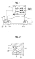
- the laser radar device is generally installed on a front bumper of a vehicle.
- the laser radar device radiates a laser beam forward in a predetermined angle relative to the reference plane such as the ground plane as long as the vehicle posture is stable, for instance, when the vehicle is at rest or in a cruising condition.
- the laser radar device is enabled to receive a reflected beam from a front object and detect the front object as the forward condition based on the received beam.
- the laser beam is radiated in the more upward direction than in the predetermined angle direction, when the vehicle is loaded with heavy stuff at the rear side or the vehicle is accelerated.
- the laser beam is radiated in the more downward direction than in the predetermined angle direction, when the vehicle is decelerated. In those instances, the forward condition detecting operation will be affected by the vehicle posture.
- a forward condition detecting apparatus for vehicles has a laser radar device which detects forward condition of a vehicle.
- An electronic control unit calculates an angle of inclination of the vehicle.
- the electronic control unit then calculates a radiation angle based on the calculated angle of inclination.
- the electronic control controls an angular position of the laser radar device based on the calculated radiation angle so that a laser beam may be maintained radiated generally in parallel with the reference plane irrespective of the inclination of the vehicle.
- the angle of inclination of the vehicle is calculated based on a difference between a front height and a rear height of the vehicle.
- the laser radar device is provided in a front headlight unit and driven together with a front headlight lamp in response to the calculated angle of inclination.
- a front height sensor 11F and a rear height sensor 11R are attached to a front wheel-side suspension and a rear wheel-side suspension of a vehicle, respectively.
- the front suspension is provided between a vehicle chassis and a front axle of either right or left side
- the rear suspension is provided between the vehicle chassis and a rear axle of either right or left side.
- the front height sensor 11F detects a relative distance between the vehicle chassis and the front axle
- the rear height sensor 11R detects a relative distance between the vehicle chassis and the rear axle.
- the detected distances indicate a front height HF and a rear height HR of the vehicle, respectively.
- Output signals of the height sensors 11F and 11R are input to an electronic control unit (ECU) 20 together with other sensor output signals, so that a laser radar device 30 installed in a front bumper 15 below a headlight unit 10 is controlled electronically through an actuator 35 from time to time.
- ECU electronice control unit
- the ECU 20 includes a central processing unit (CPU) 21, a read-only memory (ROM) 22 for storing a control program and control constants, a random access memory (RAM) 23 for storing various data, a backup RAM 24, an input/output circuit 25, and a bus 26 connecting those circuits.
- the ECU 20 thus operate as a logical arithmetic unit which controls the laser beam radiation angle radiated from the laser radar device 30.
- the laser radar device 30 is constructed with a housing 31, a fixed support 33, a movable link 34 and the actuator 35 such as a stepper motor.
- the housing 31 accommodates therein a laser beam generator (not shown) and a reflected beam receiver (not shown).
- the fixed support 33 supports the housing 31 swingably in an arrow direction.
- the movable link 34 connects the housing 31 with the actuator 35, so that the housing 31 swings in correspondence with horizontal movement of the link 34 when the link 34 is driven by the actuator 35.
- the laser radar device 30 is designed in such a manner that the laser beam is radiated at a predetermined angle relative to a reference plane (e.g., ground plane) assuming that only a driver is in the vehicle. That is, the laser beam is radiated normally with the predetermined angle being 0°, in parallel with the ground plane.
- a reference plane e.g., ground plane
- the ECU 20, particularly the CPU 21 executes a control process as shown in Fig. 3 based on a control program stored in the ROM 22. This control process may be executed every predetermined time interval.
- the CPU 21 reads in the front height HF and the rear height HR detected by the front height sensor 11F and the rear height sensor 11R, respectively, at step 101.
- the CPU 21 calculates the pitch angle ⁇ p (°) as follows relative to the predetermined reference plane (ground plane) by using the detected heights HF and HR and assuming a wheel base between the front axle and the rear axle is Lw.
- the pitch angle ⁇ p indicates inclination of the vehicle in the vehicle travel direction.
- ⁇ p tan -1 ⁇ (HF - HR) / Lw ⁇
- the CPU 21 calculates a radiation angle ⁇ T at step 103 based on the calculated inclination angle ⁇ p so that the laser beam radiation angle is maintained in parallel with the ground plane. That is, the radiation angle ⁇ T is calculated as ⁇ T ⁇ - ⁇ p. This angle ⁇ T is a corrective value by which the radiation angle caused by the vehicle inclination ( ⁇ p) is corrected to the predetermined angle (0°).
- the CPU 21 then drives at step 104 the actuator 35 through the I/O circuit 25 based on the calculated value ⁇ T so that the laser beam may be maintained radiated at the predetermined angle relative the ground plane.
- the laser beam radiation is automatically corrected to the generally horizontal direction (solid line) from the upward-headed direction (dotted line) even when the vehicle front side is raised due to vehicle acceleration or heavy loading at the rear of the vehicle.
- the laser beam radiation is automatically corrected to the generally horizontal direction (solid line) from the downward-headed direction (dotted line) even when the vehicle rear side is raised due to vehicle deceleration.
- the laser radar device 30 is automatically leveled in such a manner the laser beam radiation angle can be maintained at a fixed angle irrespective of changes in the vehicle posture so that any front condition existing ahead of the vehicle can be detected accurately.
- the laser beam radiation angle may be calculated by using only one of the front height HF or the rear height HR. It may also be calculated by detecting acceleration and deceleration of a vehicle. Further, the laser beam radiation angle may be corrected by filtering processing such as a moving average processing, which correspond to vehicle stop, cruising and acceleration/deceleration conditions, by detecting a vehicle speed and acceleration/deceleration magnitude.
- filtering processing such as a moving average processing, which correspond to vehicle stop, cruising and acceleration/deceleration conditions, by detecting a vehicle speed and acceleration/deceleration magnitude.
- the laser radar device 30 is comprised of, as shown in Figs. 5A, 5B, 6A and 6B, a laser beam generator 301a, a polygon mirror 301b and a drive motor 301c, which form a laser beam radiator 301 in the known manner. Other components such as a laser beam receiver (not shown) are not shown in the figures.
- the polygon mirror 301b which reflects the laser beam from the laser generator 301a frontward when rotated by the drive motor 301c, has a plurality of inclined surfaces around its axis of rotation. The surfaces are inclined by predetermined angles ⁇ i against the horizontal plane, respectively. The angles ⁇ i are different from each other, so that the reflected laser beams are directed up and down in each rotation of the polygon mirror 301b.
- the inclination of the vehicle (pitch angle ⁇ p) is normally considered to vary in the range of +3° and -3° from the horizontal plane. If the laser radar device 30 is fixed to the vehicle chassis such as a front bumper and no automatic leveling is provided for the laser radar device 30, the polygon mirror 301b is required to have eight inclined surfaces (numbered from 1 to 8 in Fig. 6B) to cover the above variation in the pitch angle ⁇ p.
- the laser radar device 30 is automatically leveled, thus minimizing the range of variations in the angle of radiation of the laser beam, which the laser radar device 30 is required to cover.
- the number of surfaces of the polygon mirror 301b can be reduced to four (numbered from 1 to 4) as shown in Fig. 5B.
- the polygon mirror 301b can be sized small and the laser beam generator 301a can be positioned close to the polygon mirror 301b, thus enabling use of a compact-sized laser radar device.
- the laser radar device 30 is mounted in the headlight unit 10 which is disposed right above the front bumper 15 (Fig. 1).
- the front headlight unit 10 has a cover lens 10a at the front side and a housing 12, which jointly define a closed chamber therein.
- a headlight lamp (not shown) is fixed to a reflector 13, and the reflector 3 is fixed to a board 17.
- a design panel 16 is attached to the housing 12 at a position ahead of the reflector 13.
- the board 17 is attached to a support member 36 at a top side end thereof and to the movable link 34 at a bottom side end thereof.
- the laser radar device 30 comprising the laser beam radiator 301 and a laser beam receiver 302 is fixedly attached to the board 17.
- the movable link 34 is coupled to the actuator 35 so that the bottom side of the board 17 is moved by the actuator 35 pivotally around its top side supported by the support member 36.
- the angles of radiation of the laser beam from the laser beam radiator 301 and the headlight from the reflector 17 are regulated simultaneously in response to the inclination of a vehicle by the ECU 20 in the same manner as in the first embodiment.
- the laser beam radiator 301 and the laser beam receiver 302 may be provided at separate locations on the board 17 or the reflector 13.
- the laser radar device 30 can be protected from dust and water by the cover lens 10a in addition to the automatic leveling of the angle of laser beam radiation. Further, the radiation angle of both headlight and laser beam can be automatically regulated by one actuator 35.
Abstract
Description
Claims (7)
- A forward condition detecting apparatus for vehicles comprising:parameter detecting means (11F, 11R) for detecting a parameter variable with inclination of a vehicle;angle calculating means (20, 102) for calculating an angle of inclination of the vehicle relative to a reference plane based on the detected parameter;forward condition detecting means (30) movably installed on the vehicle for detecting forward condition of the vehicle; andcontrol means (20, 35, 104) for controlling an angle of the forward condition detecting means (30) based on the calculated angle of inclination of the vehicle.
- The forward condition detecting apparatus as in claim 1, wherein the parameter detecting means (11F, 11R) includes a vehicle height sensor which detects a height of the vehicle.
- The forward condition detecting apparatus as in claim 1 or 2, wherein the forward condition detecting means (30) includes a laser radar device (301, 302) installed on a front bumper (15) of the vehicle.
- The forward condition detecting apparatus as in any one of claims 1 to 3, wherein the control means (20, 35, 104) compensates for a change of the angle of the forward condition detecting means (30) caused by a change in the angle of inclination of the vehicle.
- The forward condition detecting apparatus as in any one of claims 1 to 4, wherein:the parameter detecting means (11F, 11R) detects a front height and a rear height of the vehicle; andthe angle calculating means (20, 102) calculates the angle of inclination of the vehicle based on a difference between the front height and the rear height.
- The forward condition detecting apparatus as in claim 1 or 2, wherein the forward condition detecting means (30) includes a laser radar device (301, 302) installed within a headlight unit (10) of the vehicle.
- The forward condition detecting apparatus as in claim 6, wherein the laser radar device (301, 302) is coupled with a headlight lamp of the headlight unit (10) to be moved together with the head lamp by the control means (20, 35, 104).
Applications Claiming Priority (4)
| Application Number | Priority Date | Filing Date | Title |
|---|---|---|---|
| JP2000056579 | 2000-03-02 | ||
| JP2000056579 | 2000-03-02 | ||
| JP2000078433 | 2000-03-21 | ||
| JP2000078433A JP2001260777A (en) | 2000-03-21 | 2000-03-21 | Vehicle headlight device |
Publications (2)
| Publication Number | Publication Date |
|---|---|
| EP1130416A2 true EP1130416A2 (en) | 2001-09-05 |
| EP1130416A3 EP1130416A3 (en) | 2002-01-30 |
Family
ID=26586573
Family Applications (1)
| Application Number | Title | Priority Date | Filing Date |
|---|---|---|---|
| EP01104730A Withdrawn EP1130416A3 (en) | 2000-03-02 | 2001-02-26 | Forward condition detecting apparatus for vehicles |
Country Status (2)
| Country | Link |
|---|---|
| US (1) | US6459476B2 (en) |
| EP (1) | EP1130416A3 (en) |
Cited By (16)
| Publication number | Priority date | Publication date | Assignee | Title |
|---|---|---|---|---|
| DE10217294A1 (en) * | 2002-04-18 | 2003-11-06 | Sick Ag | sensor orientation |
| GB2392035A (en) * | 2002-07-16 | 2004-02-18 | Visteon Global Tech Inc | Vehicle lamp incorporating a sensor and data transmission means |
| DE10244639A1 (en) * | 2002-09-25 | 2004-04-08 | Ibeo Automobile Sensor Gmbh | Optoelectronic detection device |
| EP1873552A1 (en) | 2006-06-27 | 2008-01-02 | Robert Bosch Gmbh | Method and device for determining the vertical or horizontal angle error of an all-round sensor in a motor vehicle |
| EP1875123A1 (en) * | 2005-04-29 | 2008-01-09 | Osram Opto Semiconductors GmbH | Motor-vehicle headlamp |
| EP1914564A1 (en) * | 2006-10-19 | 2008-04-23 | Sick Ag | Optical detection device |
| EP1965225A3 (en) * | 2007-02-28 | 2009-07-15 | Denso Wave Incorporated | Laser radar apparatus for three-dimensional detection of objects |
| EP2144081A1 (en) * | 2008-07-10 | 2010-01-13 | Valeo Schalter und Sensoren GmbH | Method and device for controlling sensors of a surroundings monitoring system for vehicles |
| CN105717500A (en) * | 2016-02-24 | 2016-06-29 | 深圳乐行天下科技有限公司 | Laser radar and data correcting method thereof |
| EP2988060A4 (en) * | 2013-04-15 | 2016-11-30 | Koito Mfg Co Ltd | Lamp for a vehicle |
| CN106838757A (en) * | 2015-12-07 | 2017-06-13 | 通用汽车环球科技运作有限责任公司 | Exterior lighting and object detection component |
| WO2018077263A1 (en) * | 2016-10-31 | 2018-05-03 | 张舒怡 | Sensor for automatic driving |
| WO2019140792A1 (en) * | 2018-01-17 | 2019-07-25 | 上海禾赛光电科技有限公司 | Detection apparatus and parameter adjustment method thereof |
| CN111239767A (en) * | 2018-11-27 | 2020-06-05 | 现代自动车株式会社 | Object sensing apparatus |
| WO2020114952A1 (en) * | 2018-12-04 | 2020-06-11 | Bayerische Motoren Werke Aktiengesellschaft | Method and device for calibrating an environment sensor of a vehicle |
| DE102021115658A1 (en) | 2021-06-17 | 2022-12-22 | Audi Aktiengesellschaft | Lighting device for a motor vehicle, motor vehicle |
Families Citing this family (25)
| Publication number | Priority date | Publication date | Assignee | Title |
|---|---|---|---|---|
| US7241034B2 (en) * | 2001-10-31 | 2007-07-10 | Dana Corporation | Automatic directional control system for vehicle headlights |
| JP2005145301A (en) * | 2003-11-17 | 2005-06-09 | Denso Corp | Driving assisting device for vehicle |
| DE102004006133B4 (en) * | 2004-02-07 | 2006-11-23 | Bayerische Motoren Werke Ag | Device for headlight range adjustment of a motor vehicle |
| JP4444265B2 (en) * | 2006-11-27 | 2010-03-31 | 富士通テン株式会社 | Vehicular radar apparatus and method for manufacturing the same, reference section, and adjustment method of beam emitting direction |
| JP2008146933A (en) * | 2006-12-07 | 2008-06-26 | Koito Mfg Co Ltd | Vehicular lamp |
| JP2008162391A (en) * | 2006-12-27 | 2008-07-17 | Koito Mfg Co Ltd | Vehicular lamp |
| JP4842161B2 (en) * | 2007-01-31 | 2011-12-21 | 株式会社小糸製作所 | Vehicle lighting |
| JP4711983B2 (en) * | 2007-02-21 | 2011-06-29 | 株式会社小糸製作所 | Vehicle lamp |
| DE102009009227B4 (en) | 2008-02-21 | 2021-10-07 | Adc Automotive Distance Control Systems Gmbh | Method for the automatic alignment of a radiation sensor in a vehicle |
| US8232909B2 (en) | 2008-09-30 | 2012-07-31 | Cooper Technologies Company | Doppler radar motion detector for an outdoor light fixture |
| JP4986173B2 (en) * | 2008-10-07 | 2012-07-25 | オムロンオートモーティブエレクトロニクス株式会社 | Auto-leveling device and auto-leveling method |
| JP4919179B2 (en) * | 2010-05-11 | 2012-04-18 | 独立行政法人電子航法研究所 | Millimeter wave radar built-in headlamp |
| US8692980B2 (en) | 2010-11-01 | 2014-04-08 | Advanced Scientific Concepts, Inc. | Flash LADAR collision avoidance system |
| DE102011077333A1 (en) * | 2011-06-10 | 2012-12-27 | Robert Bosch Gmbh | Driver assistance system with object detection |
| JP6048199B2 (en) * | 2012-03-22 | 2016-12-21 | 株式会社デンソー | Vehicle lighting device |
| US8833815B2 (en) * | 2012-10-23 | 2014-09-16 | Ford Global Technologies, Llc | Bumper integrated forward radar mounting system |
| AT514218B1 (en) * | 2013-05-06 | 2015-05-15 | Bluetechnix Gmbh | vehicle headlights |
| JP7105199B2 (en) | 2016-12-28 | 2022-07-22 | 株式会社小糸製作所 | lamp device |
| CN108072880A (en) * | 2018-01-17 | 2018-05-25 | 上海禾赛光电科技有限公司 | The method of adjustment of laser radar field of view center direction, medium, laser radar system |
| JPWO2019172118A1 (en) | 2018-03-05 | 2021-02-18 | 株式会社小糸製作所 | Sensor systems, sensor modules, and lamp devices |
| CN110271500B (en) * | 2018-03-16 | 2023-05-23 | 株式会社小糸制作所 | Sensor system |
| EP3614167B1 (en) | 2018-08-23 | 2022-07-20 | NXP USA, Inc. | Vehicle radar sensor and method of operation |
| JP7356451B2 (en) * | 2018-11-27 | 2023-10-04 | 株式会社小糸製作所 | sensor system |
| US11264707B2 (en) | 2019-11-20 | 2022-03-01 | Toyota Motor Engineering & Manufacturing North America, Inc. | Antenna apparatus and related communication systems for use with vehicle lamps |
| KR20230004129A (en) * | 2021-06-30 | 2023-01-06 | 현대모비스 주식회사 | Control apparatus of lamp and operating method of the same, vehicle |
Citations (4)
| Publication number | Priority date | Publication date | Assignee | Title |
|---|---|---|---|---|
| US5313213A (en) * | 1992-01-18 | 1994-05-17 | Mercedes-Benz Ag | Device for aligning a directional antenna of a radar distance warning device of a vehicle |
| US5808728A (en) * | 1994-10-21 | 1998-09-15 | Mitsubishi Denki Kabushiki Kaisha | Vehicle environment monitoring system |
| JPH11194169A (en) * | 1997-12-27 | 1999-07-21 | Honda Motor Co Ltd | Object detection device for vehicle |
| EP0965487A2 (en) * | 1998-06-16 | 1999-12-22 | Denso Corporation | System for automatically adjusting optical axis direction of vehicle headlight |
Family Cites Families (8)
| Publication number | Priority date | Publication date | Assignee | Title |
|---|---|---|---|---|
| JPS63281088A (en) | 1987-05-13 | 1988-11-17 | Koito Mfg Co Ltd | Obstacle detector for automobile |
| JPH03131790A (en) | 1989-10-18 | 1991-06-05 | Nippon Soken Inc | Obstacle detecting device for vehicle |
| DE19650863C1 (en) * | 1996-12-07 | 1998-04-16 | Bosch Gmbh Robert | Method of detecting distance sensor vertical adjustment error |
| EP0847895B1 (en) * | 1996-12-13 | 2001-08-01 | Denso Corporation | Apparatus for automatically adjusting aiming of headlights of an automotive vehicle |
| JPH11142520A (en) * | 1997-11-06 | 1999-05-28 | Omron Corp | Axis adjusting method for distance measuring apparatus and detecting method for axis deviation as well as distance measuring apparatus |
| JP3462740B2 (en) * | 1998-01-06 | 2003-11-05 | 株式会社日立製作所 | Axis adjustment method for automotive radar |
| JP3518309B2 (en) * | 1998-02-02 | 2004-04-12 | 日産自動車株式会社 | Vehicle pitch angle calculation device |
| JPH11321598A (en) * | 1998-05-07 | 1999-11-24 | Honda Motor Co Ltd | Safety device for running of vehicle |
-
2001
- 2001-02-26 EP EP01104730A patent/EP1130416A3/en not_active Withdrawn
- 2001-03-01 US US09/795,707 patent/US6459476B2/en not_active Expired - Lifetime
Patent Citations (4)
| Publication number | Priority date | Publication date | Assignee | Title |
|---|---|---|---|---|
| US5313213A (en) * | 1992-01-18 | 1994-05-17 | Mercedes-Benz Ag | Device for aligning a directional antenna of a radar distance warning device of a vehicle |
| US5808728A (en) * | 1994-10-21 | 1998-09-15 | Mitsubishi Denki Kabushiki Kaisha | Vehicle environment monitoring system |
| JPH11194169A (en) * | 1997-12-27 | 1999-07-21 | Honda Motor Co Ltd | Object detection device for vehicle |
| EP0965487A2 (en) * | 1998-06-16 | 1999-12-22 | Denso Corporation | System for automatically adjusting optical axis direction of vehicle headlight |
Non-Patent Citations (1)
| Title |
|---|
| PATENT ABSTRACTS OF JAPAN vol. 1999, no. 12, 29 October 1999 (1999-10-29) & JP 11 194169 A (HONDA MOTOR CO LTD), 21 July 1999 (1999-07-21) -& US 6 157 294 A 5 December 2000 (2000-12-05) * |
Cited By (24)
| Publication number | Priority date | Publication date | Assignee | Title |
|---|---|---|---|---|
| DE10217294A1 (en) * | 2002-04-18 | 2003-11-06 | Sick Ag | sensor orientation |
| GB2392035A (en) * | 2002-07-16 | 2004-02-18 | Visteon Global Tech Inc | Vehicle lamp incorporating a sensor and data transmission means |
| GB2392035B (en) * | 2002-07-16 | 2004-08-11 | Visteon Global Tech Inc | Vehicle lamp and vehicle illumination and data transmission system incorporating same |
| US6821003B2 (en) | 2002-07-16 | 2004-11-23 | Visteon Global Technologies, Inc. | Vehicle lamp and vehicle illumination and data transmission system incorporating same |
| DE10244639A1 (en) * | 2002-09-25 | 2004-04-08 | Ibeo Automobile Sensor Gmbh | Optoelectronic detection device |
| EP1875123A1 (en) * | 2005-04-29 | 2008-01-09 | Osram Opto Semiconductors GmbH | Motor-vehicle headlamp |
| EP1875123B1 (en) * | 2005-04-29 | 2016-05-18 | OSRAM Opto Semiconductors GmbH | Motor-vehicle headlamp |
| EP1873552A1 (en) | 2006-06-27 | 2008-01-02 | Robert Bosch Gmbh | Method and device for determining the vertical or horizontal angle error of an all-round sensor in a motor vehicle |
| EP1914564A1 (en) * | 2006-10-19 | 2008-04-23 | Sick Ag | Optical detection device |
| EP1965225A3 (en) * | 2007-02-28 | 2009-07-15 | Denso Wave Incorporated | Laser radar apparatus for three-dimensional detection of objects |
| US7880865B2 (en) | 2007-02-28 | 2011-02-01 | Denso Wave Incorporated | Laser radar apparatus for three-dimensional detection of objects |
| EP2144081A1 (en) * | 2008-07-10 | 2010-01-13 | Valeo Schalter und Sensoren GmbH | Method and device for controlling sensors of a surroundings monitoring system for vehicles |
| EP2988060A4 (en) * | 2013-04-15 | 2016-11-30 | Koito Mfg Co Ltd | Lamp for a vehicle |
| CN106838757B (en) * | 2015-12-07 | 2019-08-02 | 通用汽车环球科技运作有限责任公司 | Exterior lighting and object detection component |
| CN106838757A (en) * | 2015-12-07 | 2017-06-13 | 通用汽车环球科技运作有限责任公司 | Exterior lighting and object detection component |
| CN105717500A (en) * | 2016-02-24 | 2016-06-29 | 深圳乐行天下科技有限公司 | Laser radar and data correcting method thereof |
| WO2018077263A1 (en) * | 2016-10-31 | 2018-05-03 | 张舒怡 | Sensor for automatic driving |
| WO2019140792A1 (en) * | 2018-01-17 | 2019-07-25 | 上海禾赛光电科技有限公司 | Detection apparatus and parameter adjustment method thereof |
| US11346926B2 (en) | 2018-01-17 | 2022-05-31 | Hesai Technology Co., Ltd. | Detection device and method for adjusting parameter thereof |
| CN111239767A (en) * | 2018-11-27 | 2020-06-05 | 现代自动车株式会社 | Object sensing apparatus |
| US11417112B2 (en) * | 2018-11-27 | 2022-08-16 | Hyundai Motor Company | Object sensing apparatus |
| WO2020114952A1 (en) * | 2018-12-04 | 2020-06-11 | Bayerische Motoren Werke Aktiengesellschaft | Method and device for calibrating an environment sensor of a vehicle |
| DE102021115658A1 (en) | 2021-06-17 | 2022-12-22 | Audi Aktiengesellschaft | Lighting device for a motor vehicle, motor vehicle |
| DE102021115658B4 (en) | 2021-06-17 | 2023-01-26 | Audi Aktiengesellschaft | Lighting device for a motor vehicle, motor vehicle |
Also Published As
| Publication number | Publication date |
|---|---|
| EP1130416A3 (en) | 2002-01-30 |
| US6459476B2 (en) | 2002-10-01 |
| US20010024171A1 (en) | 2001-09-27 |
Similar Documents
| Publication | Publication Date | Title |
|---|---|---|
| EP1130416A2 (en) | Forward condition detecting apparatus for vehicles | |
| US6087975A (en) | Object detecting system for vehicle | |
| KR102313025B1 (en) | Vehicle and method for controlling thereof | |
| US7650239B2 (en) | Object recognition apparatus for motor vehicle | |
| US6572248B2 (en) | Apparatus for automatically adjusting optical axis of vehicle headlights | |
| JP5947947B2 (en) | VEHICLE LIGHT CONTROL DEVICE, VEHICLE LIGHT SYSTEM, AND VEHICLE LIGHT | |
| US5193894A (en) | Apparatus and method for controlling the light-range of motor vehicle headlights | |
| JP3384236B2 (en) | Automatic adjustment of headlight optical axis direction for vehicles | |
| US7241034B2 (en) | Automatic directional control system for vehicle headlights | |
| KR20080102158A (en) | System for regulating the position of the chassis of a motor vehicle | |
| US6480806B1 (en) | Automatic headlight leveling system for motor vehicles | |
| KR20180095660A (en) | Lada scanning device on the car | |
| EP2514636A2 (en) | Control device for vehicle lamp and vehicle lamp system | |
| US6275145B1 (en) | Apparatus to help prevent temporary blinding of drivers | |
| JPH09207654A (en) | Irradiation direction control device for vehicle lighting fixture | |
| US9902201B2 (en) | Method and devices for detecting and rectifying problems in connection with a vehicle load | |
| US6332698B1 (en) | Automatic leveling apparatus for use with vehicle headlamps | |
| US20120294020A1 (en) | Control apparatus for vehicle lamp and vehicle lamp system | |
| KR102486163B1 (en) | Vehicle and method for controlling the same | |
| JP2001318149A (en) | Front information detecting device for vehicle | |
| US6389344B1 (en) | Automatic headlight aiming device for a vehicle | |
| JP4145812B2 (en) | Auto-leveling device for automotive headlamps | |
| JP2021138278A (en) | Controller for vehicular lighting fixture and vehicular lighting fixture system | |
| JP5405750B2 (en) | Optical axis adjustment device for vehicle headlamp | |
| JP5596845B2 (en) | Optical axis adjustment device for vehicle headlamp |
Legal Events
| Date | Code | Title | Description |
|---|---|---|---|
| PUAI | Public reference made under article 153(3) epc to a published international application that has entered the european phase |
Free format text: ORIGINAL CODE: 0009012 |
|
| AK | Designated contracting states |
Kind code of ref document: A2 Designated state(s): DE FR GB IT Kind code of ref document: A2 Designated state(s): AT BE CH CY DE DK ES FI FR GB GR IE IT LI LU MC NL PT SE TR |
|
| AX | Request for extension of the european patent |
Free format text: AL;LT;LV;MK;RO;SI |
|
| PUAL | Search report despatched |
Free format text: ORIGINAL CODE: 0009013 |
|
| AK | Designated contracting states |
Kind code of ref document: A3 Designated state(s): AT BE CH CY DE DK ES FI FR GB GR IE IT LI LU MC NL PT SE TR |
|
| AX | Request for extension of the european patent |
Free format text: AL;LT;LV;MK;RO;SI |
|
| RIC1 | Information provided on ipc code assigned before grant |
Free format text: 7G 01S 7/497 A, 7G 01S 7/481 B, 7G 01S 17/88 B, 7G 01S 17/93 B |
|
| 17P | Request for examination filed |
Effective date: 20020405 |
|
| 17Q | First examination report despatched |
Effective date: 20020816 |
|
| AKX | Designation fees paid |
Free format text: DE FR GB IT |
|
| STAA | Information on the status of an ep patent application or granted ep patent |
Free format text: STATUS: THE APPLICATION IS DEEMED TO BE WITHDRAWN |
|
| 18D | Application deemed to be withdrawn |
Effective date: 20030409 |