EP1132499B1 - Alloy coating, method for forming the same, and member for high temperature apparatuses - Google Patents
Alloy coating, method for forming the same, and member for high temperature apparatuses Download PDFInfo
- Publication number
- EP1132499B1 EP1132499B1 EP01105658A EP01105658A EP1132499B1 EP 1132499 B1 EP1132499 B1 EP 1132499B1 EP 01105658 A EP01105658 A EP 01105658A EP 01105658 A EP01105658 A EP 01105658A EP 1132499 B1 EP1132499 B1 EP 1132499B1
- Authority
- EP
- European Patent Office
- Prior art keywords
- coating
- substrate
- alloy
- single crystal
- base single
- Prior art date
- Legal status (The legal status is an assumption and is not a legal conclusion. Google has not performed a legal analysis and makes no representation as to the accuracy of the status listed.)
- Expired - Lifetime
Links
Images

Classifications
-
- F—MECHANICAL ENGINEERING; LIGHTING; HEATING; WEAPONS; BLASTING
- F01—MACHINES OR ENGINES IN GENERAL; ENGINE PLANTS IN GENERAL; STEAM ENGINES
- F01D—NON-POSITIVE DISPLACEMENT MACHINES OR ENGINES, e.g. STEAM TURBINES
- F01D5/00—Blades; Blade-carrying members; Heating, heat-insulating, cooling or antivibration means on the blades or the members
- F01D5/12—Blades
- F01D5/28—Selecting particular materials; Particular measures relating thereto; Measures against erosion or corrosion
- F01D5/288—Protective coatings for blades
-
- C—CHEMISTRY; METALLURGY
- C23—COATING METALLIC MATERIAL; COATING MATERIAL WITH METALLIC MATERIAL; CHEMICAL SURFACE TREATMENT; DIFFUSION TREATMENT OF METALLIC MATERIAL; COATING BY VACUUM EVAPORATION, BY SPUTTERING, BY ION IMPLANTATION OR BY CHEMICAL VAPOUR DEPOSITION, IN GENERAL; INHIBITING CORROSION OF METALLIC MATERIAL OR INCRUSTATION IN GENERAL
- C23C—COATING METALLIC MATERIAL; COATING MATERIAL WITH METALLIC MATERIAL; SURFACE TREATMENT OF METALLIC MATERIAL BY DIFFUSION INTO THE SURFACE, BY CHEMICAL CONVERSION OR SUBSTITUTION; COATING BY VACUUM EVAPORATION, BY SPUTTERING, BY ION IMPLANTATION OR BY CHEMICAL VAPOUR DEPOSITION, IN GENERAL
- C23C28/00—Coating for obtaining at least two superposed coatings either by methods not provided for in a single one of groups C23C2/00 - C23C26/00 or by combinations of methods provided for in subclasses C23C and C25C or C25D
- C23C28/30—Coatings combining at least one metallic layer and at least one inorganic non-metallic layer
- C23C28/32—Coatings combining at least one metallic layer and at least one inorganic non-metallic layer including at least one pure metallic layer
- C23C28/321—Coatings combining at least one metallic layer and at least one inorganic non-metallic layer including at least one pure metallic layer with at least one metal alloy layer
-
- C—CHEMISTRY; METALLURGY
- C23—COATING METALLIC MATERIAL; COATING MATERIAL WITH METALLIC MATERIAL; CHEMICAL SURFACE TREATMENT; DIFFUSION TREATMENT OF METALLIC MATERIAL; COATING BY VACUUM EVAPORATION, BY SPUTTERING, BY ION IMPLANTATION OR BY CHEMICAL VAPOUR DEPOSITION, IN GENERAL; INHIBITING CORROSION OF METALLIC MATERIAL OR INCRUSTATION IN GENERAL
- C23C—COATING METALLIC MATERIAL; COATING MATERIAL WITH METALLIC MATERIAL; SURFACE TREATMENT OF METALLIC MATERIAL BY DIFFUSION INTO THE SURFACE, BY CHEMICAL CONVERSION OR SUBSTITUTION; COATING BY VACUUM EVAPORATION, BY SPUTTERING, BY ION IMPLANTATION OR BY CHEMICAL VAPOUR DEPOSITION, IN GENERAL
- C23C28/00—Coating for obtaining at least two superposed coatings either by methods not provided for in a single one of groups C23C2/00 - C23C26/00 or by combinations of methods provided for in subclasses C23C and C25C or C25D
- C23C28/30—Coatings combining at least one metallic layer and at least one inorganic non-metallic layer
- C23C28/32—Coatings combining at least one metallic layer and at least one inorganic non-metallic layer including at least one pure metallic layer
- C23C28/325—Coatings combining at least one metallic layer and at least one inorganic non-metallic layer including at least one pure metallic layer with layers graded in composition or in physical properties
-
- C—CHEMISTRY; METALLURGY
- C23—COATING METALLIC MATERIAL; COATING MATERIAL WITH METALLIC MATERIAL; CHEMICAL SURFACE TREATMENT; DIFFUSION TREATMENT OF METALLIC MATERIAL; COATING BY VACUUM EVAPORATION, BY SPUTTERING, BY ION IMPLANTATION OR BY CHEMICAL VAPOUR DEPOSITION, IN GENERAL; INHIBITING CORROSION OF METALLIC MATERIAL OR INCRUSTATION IN GENERAL
- C23C—COATING METALLIC MATERIAL; COATING MATERIAL WITH METALLIC MATERIAL; SURFACE TREATMENT OF METALLIC MATERIAL BY DIFFUSION INTO THE SURFACE, BY CHEMICAL CONVERSION OR SUBSTITUTION; COATING BY VACUUM EVAPORATION, BY SPUTTERING, BY ION IMPLANTATION OR BY CHEMICAL VAPOUR DEPOSITION, IN GENERAL
- C23C28/00—Coating for obtaining at least two superposed coatings either by methods not provided for in a single one of groups C23C2/00 - C23C26/00 or by combinations of methods provided for in subclasses C23C and C25C or C25D
- C23C28/30—Coatings combining at least one metallic layer and at least one inorganic non-metallic layer
- C23C28/34—Coatings combining at least one metallic layer and at least one inorganic non-metallic layer including at least one inorganic non-metallic material layer, e.g. metal carbide, nitride, boride, silicide layer and their mixtures, enamels, phosphates and sulphates
- C23C28/345—Coatings combining at least one metallic layer and at least one inorganic non-metallic layer including at least one inorganic non-metallic material layer, e.g. metal carbide, nitride, boride, silicide layer and their mixtures, enamels, phosphates and sulphates with at least one oxide layer
- C23C28/3455—Coatings combining at least one metallic layer and at least one inorganic non-metallic layer including at least one inorganic non-metallic material layer, e.g. metal carbide, nitride, boride, silicide layer and their mixtures, enamels, phosphates and sulphates with at least one oxide layer with a refractory ceramic layer, e.g. refractory metal oxide, ZrO2, rare earth oxides or a thermal barrier system comprising at least one refractory oxide layer
-
- C—CHEMISTRY; METALLURGY
- C23—COATING METALLIC MATERIAL; COATING MATERIAL WITH METALLIC MATERIAL; CHEMICAL SURFACE TREATMENT; DIFFUSION TREATMENT OF METALLIC MATERIAL; COATING BY VACUUM EVAPORATION, BY SPUTTERING, BY ION IMPLANTATION OR BY CHEMICAL VAPOUR DEPOSITION, IN GENERAL; INHIBITING CORROSION OF METALLIC MATERIAL OR INCRUSTATION IN GENERAL
- C23C—COATING METALLIC MATERIAL; COATING MATERIAL WITH METALLIC MATERIAL; SURFACE TREATMENT OF METALLIC MATERIAL BY DIFFUSION INTO THE SURFACE, BY CHEMICAL CONVERSION OR SUBSTITUTION; COATING BY VACUUM EVAPORATION, BY SPUTTERING, BY ION IMPLANTATION OR BY CHEMICAL VAPOUR DEPOSITION, IN GENERAL
- C23C30/00—Coating with metallic material characterised only by the composition of the metallic material, i.e. not characterised by the coating process
-
- C—CHEMISTRY; METALLURGY
- C25—ELECTROLYTIC OR ELECTROPHORETIC PROCESSES; APPARATUS THEREFOR
- C25D—PROCESSES FOR THE ELECTROLYTIC OR ELECTROPHORETIC PRODUCTION OF COATINGS; ELECTROFORMING; APPARATUS THEREFOR
- C25D3/00—Electroplating: Baths therefor
- C25D3/02—Electroplating: Baths therefor from solutions
- C25D3/54—Electroplating: Baths therefor from solutions of metals not provided for in groups C25D3/04 - C25D3/50
-
- C—CHEMISTRY; METALLURGY
- C25—ELECTROLYTIC OR ELECTROPHORETIC PROCESSES; APPARATUS THEREFOR
- C25D—PROCESSES FOR THE ELECTROLYTIC OR ELECTROPHORETIC PRODUCTION OF COATINGS; ELECTROFORMING; APPARATUS THEREFOR
- C25D3/00—Electroplating: Baths therefor
- C25D3/66—Electroplating: Baths therefor from melts
-
- F—MECHANICAL ENGINEERING; LIGHTING; HEATING; WEAPONS; BLASTING
- F05—INDEXING SCHEMES RELATING TO ENGINES OR PUMPS IN VARIOUS SUBCLASSES OF CLASSES F01-F04
- F05D—INDEXING SCHEME FOR ASPECTS RELATING TO NON-POSITIVE-DISPLACEMENT MACHINES OR ENGINES, GAS-TURBINES OR JET-PROPULSION PLANTS
- F05D2230/00—Manufacture
- F05D2230/90—Coating; Surface treatment
-
- F—MECHANICAL ENGINEERING; LIGHTING; HEATING; WEAPONS; BLASTING
- F05—INDEXING SCHEMES RELATING TO ENGINES OR PUMPS IN VARIOUS SUBCLASSES OF CLASSES F01-F04
- F05D—INDEXING SCHEME FOR ASPECTS RELATING TO NON-POSITIVE-DISPLACEMENT MACHINES OR ENGINES, GAS-TURBINES OR JET-PROPULSION PLANTS
- F05D2300/00—Materials; Properties thereof
- F05D2300/60—Properties or characteristics given to material by treatment or manufacturing
- F05D2300/611—Coating
-
- Y—GENERAL TAGGING OF NEW TECHNOLOGICAL DEVELOPMENTS; GENERAL TAGGING OF CROSS-SECTIONAL TECHNOLOGIES SPANNING OVER SEVERAL SECTIONS OF THE IPC; TECHNICAL SUBJECTS COVERED BY FORMER USPC CROSS-REFERENCE ART COLLECTIONS [XRACs] AND DIGESTS
- Y02—TECHNOLOGIES OR APPLICATIONS FOR MITIGATION OR ADAPTATION AGAINST CLIMATE CHANGE
- Y02T—CLIMATE CHANGE MITIGATION TECHNOLOGIES RELATED TO TRANSPORTATION
- Y02T50/00—Aeronautics or air transport
- Y02T50/60—Efficient propulsion technologies, e.g. for aircraft
-
- Y—GENERAL TAGGING OF NEW TECHNOLOGICAL DEVELOPMENTS; GENERAL TAGGING OF CROSS-SECTIONAL TECHNOLOGIES SPANNING OVER SEVERAL SECTIONS OF THE IPC; TECHNICAL SUBJECTS COVERED BY FORMER USPC CROSS-REFERENCE ART COLLECTIONS [XRACs] AND DIGESTS
- Y10—TECHNICAL SUBJECTS COVERED BY FORMER USPC
- Y10T—TECHNICAL SUBJECTS COVERED BY FORMER US CLASSIFICATION
- Y10T428/00—Stock material or miscellaneous articles
- Y10T428/12—All metal or with adjacent metals
- Y10T428/12493—Composite; i.e., plural, adjacent, spatially distinct metal components [e.g., layers, joint, etc.]
- Y10T428/12535—Composite; i.e., plural, adjacent, spatially distinct metal components [e.g., layers, joint, etc.] with additional, spatially distinct nonmetal component
- Y10T428/12583—Component contains compound of adjacent metal
- Y10T428/1259—Oxide
-
- Y—GENERAL TAGGING OF NEW TECHNOLOGICAL DEVELOPMENTS; GENERAL TAGGING OF CROSS-SECTIONAL TECHNOLOGIES SPANNING OVER SEVERAL SECTIONS OF THE IPC; TECHNICAL SUBJECTS COVERED BY FORMER USPC CROSS-REFERENCE ART COLLECTIONS [XRACs] AND DIGESTS
- Y10—TECHNICAL SUBJECTS COVERED BY FORMER USPC
- Y10T—TECHNICAL SUBJECTS COVERED BY FORMER US CLASSIFICATION
- Y10T428/00—Stock material or miscellaneous articles
- Y10T428/12—All metal or with adjacent metals
- Y10T428/12493—Composite; i.e., plural, adjacent, spatially distinct metal components [e.g., layers, joint, etc.]
- Y10T428/12771—Transition metal-base component
- Y10T428/12806—Refractory [Group IVB, VB, or VIB] metal-base component
- Y10T428/12812—Diverse refractory group metal-base components: alternative to or next to each other
-
- Y—GENERAL TAGGING OF NEW TECHNOLOGICAL DEVELOPMENTS; GENERAL TAGGING OF CROSS-SECTIONAL TECHNOLOGIES SPANNING OVER SEVERAL SECTIONS OF THE IPC; TECHNICAL SUBJECTS COVERED BY FORMER USPC CROSS-REFERENCE ART COLLECTIONS [XRACs] AND DIGESTS
- Y10—TECHNICAL SUBJECTS COVERED BY FORMER USPC
- Y10T—TECHNICAL SUBJECTS COVERED BY FORMER US CLASSIFICATION
- Y10T428/00—Stock material or miscellaneous articles
- Y10T428/12—All metal or with adjacent metals
- Y10T428/12493—Composite; i.e., plural, adjacent, spatially distinct metal components [e.g., layers, joint, etc.]
- Y10T428/12771—Transition metal-base component
- Y10T428/12861—Group VIII or IB metal-base component
- Y10T428/12875—Platinum group metal-base component
Definitions
- the present invention relates to an alloy coating for use as a surface coating which can prolong the service life of members for apparatuses for high temperature applications (hereinafter referred to as "members for high temperature apparatuses"), such as gas turbine blades, jet engines, and heat-transfer tubes for boilers, a method for forming the same, and a member for high temperature apparatuses.
- members for high temperature apparatuses such as gas turbine blades, jet engines, and heat-transfer tubes for boilers
- a coating is applied on the surface thereof to improve the heat resistance and the corrosion resistance of the members.
- a ceramic coating called “thermal barrier coating” (hereinafter referred to as "TBC"
- TBC thermal barrier coating
- Such a ceramic coating has the problem that the difference in coefficient of thermal expansion between the substrate metal and the ceramic is so large that, when a ceramic layer is directly formed on the surface of the substrate, the ceramic layer is likely to be separated from the interface of the ceramic layer and the substrate.
- an undercoat 50 formed of an alloy layer and a topcoat 52 formed of, for example, a ceramic such as ZrO 2 are laminated in that order on the surface of the substrate 10, to improve the adhesion of TBC 54 to the substrate 10.
- the undercoat 50 is reacted with the substrate 10 to form an Al-deficient layer 56 and a layer 58 of Al 2 O 3 + NiAl 2 O 4 having poor protective properties at the interface of the undercoat 50 and the substrate 10, thus resulting in deterioration of TBC 54.
- TBC 54 is porous, atmosphere gas enters the inside of TBC 54 and then internally oxidizes or internally nitrides the substrate 10 to form an internal corrosion layer containing an internal oxide 36 and an internal nitride 38 within the substrate 10. For this reason, the service life of the member for high temperature apparatuses is as short as several months.
- the protective coating cannot be stably maintained for a long period of time, resulting in a short service life of the apparatus.
- the prolongation of the service life of a member for high temperature apparatuses is only made by lowering the service temperature of the apparatus while sacrificing the performance of the apparatus.
- the TBC layer is deteriorated as a result of a reaction of TBC with the substrate during use of the members, and, in addition, the substrate is internally oxidized or internally nitrided by atmosphere gas which has penetrated into the inside of the coating.
- the spray coating of a high Ni-high Cr alloy, etc. for improving the corrosion resistance, when the apparatus is used under an environment containing Cl, S or the like, which is highly corrosive at high temperatures, the consumption rate of the element constituting the protective coating, such as Cr or Al, is so high that a stable protective coating cannot be maintained for a long period of time.
- EP 0 848 071 describes a Ni-base alloy containing Re, W, Al, Cr for high temperature apparatuses.
- an element for imparting corrosion resistance such as chromium (Cr), aluminum (Al), silicon (Si), magnesium (Mg), niobium (Nb), tantalum (
- the interposed coating is considered to function as an excellent diffusion barrier which can inhibit the deterioration of TBC, caused by a reaction of TBC with the substrate, and the internal corrosion of the substrate.
- the technique of plating in a molten salt has the advantages that 1 the thickness and composition of the coating can be easily controlled; 2 the coating can be effected with ease by using a simple apparatus; 3 a dense coating having no significant defect can be formed; 4 there is few limitations on the size and shape of a substrate to be coated; and 5 the cost is low.
- the present invention has been accomplished under the above circumstances.
- the alloy coating is formed by plating in a molten salt and comprises an alloy, said alloy comprising Re as a base member, and alloying elements Cr, Ni, W and Al for providing a corrosion resistance alloy with the base member.
- a deterioration in substrate caused by corrosion and damage can be reduced by virtue of the alloy coating, which can function as a better diffusion barrier, covering the surface of the substrate, whereby the service life of the member is prolonged.
- a thermal barrier coating may be formed on the surface of the alloy coating.
- a deterioration in thermal barrier coating, caused by the reaction of the thermal barrier coating with the substrate, and the penetration of atmosphere gas into the substrate can be prevented by virtue of the alloy coating, which can function as a better diffusion barrier, interposed between the substrate and the thermal barrier coating, whereby the service life of the member is prolonged.
- Re is used as a high-melting metal
- Al as a metallic element for imparting corrosion resistance
- FIGS. 1A and 1B show cross-sectional microstructures of Ni-base single crystal superalloys (Ni-Co-Cr-Al-W-Ta-Ti-Re-Mo alloy) having a coating, illustrative of different embodiments of the present invention, which can be used as a member for high temperature apparatuses. More specifically, FIG. 1A shows a coated Ni-base single crystal superalloy composed of a Ni-base single crystal superalloy (substrate) 10 and an alloy coating 16 covering the surface of the substrate 10, the alloy coating 16 being composed of a mixture of a Ni-Al alloy 12 with a Re-Al alloy 14.
- FIG. 1A shows a coated Ni-base single crystal superalloy composed of a Ni-base single crystal superalloy (substrate) 10 and an alloy coating 16 covering the surface of the substrate 10, the alloy coating 16 being composed of a mixture of a Ni-Al alloy 12 with a Re-Al alloy 14.
- FIG. 1A shows
- 1B shows a coated Ni-base single crystal superalloy composed of a substrate 10 and an alloy coating 16 covering the surface of the substrate 10, the alloy coating 16 being composed of a Re-Al alloy layer 18 and a Ni-Al alloy layer 20.
- Cr, W, and Ni diffused from the substrate 10 are contained in the Re-Al alloy layer, and an Al diffused layer 22 is formed at the interface between the substrate 10 and the alloy coating 16.
- the coated Ni-base single crystal superalloys having cross-sectional microstructures shown in FIGS. 1A and 1B were prepared by coating the surface of the Ni-base single crystal superalloy (substrate) 10 with a Re-Al alloy by plating in a molten salt. More specifically, in the preparation of the coated Ni-base single crystal superalloy shown in FIG.
- Al and Re were reacted with chlorine gas in an LiCl-KCl eutectic salt to produce AlCl 3 and ReCl 4 dissolved and absorbed directly in the LiCl-KCl molten salt, and this was used as the molten salt, and the surface of the substrate 10 was plated in the molten salt under the conditions of plating temperature 500°C, current 10 mA, and plating time 10 hr.
- the coated Ni-base single crystal superalloy shown in FIG. 1B was prepared by plating the substrate 10 in the same manner as described above in connection with FIG. 1A , except that the plating temperature was changed to 700°C.
- FIG. 1C shows a cross-sectional microstructure of a coated Ni-base single crystal superalloy illustrative of another embodiment of the present invention, wherein the surface of the substrate 10 has been coated with a Re-Al alloy coating 26 by sputtering.
- FIG. 1D shows a cross-sectional microstructure of a coated Ni-base single crystal superalloy, wherein the surface of the substrate 10 has been coated with a Re-Al alloy coating by sputtering, followed by Al vapor diffusion.
- the formation of a Re-Al alloy coating by sputtering followed by Al vapor diffusion results in the formation of a laminated structure of a Re-Al-(Cr-W-Ni) alloy layer 18 and a Ni-Al alloy layer 20, as with the structure shown in FIG. 1B . Further, the formation of an A1 diffused layer 22 is also observed at the substrate/coating interface. From FIGS. 1A to 1D , it is apparent that, when sputtering is solely adopted, the formed Re-Al alloy coating 26 have many cracks 26a (see FIG.
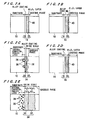
- FIGS. 2A to 2E show cross-sectional microstructures, after carrying out oxidation in air at 1150°C for 100 hr or in air at 1100°C for one month, of the coated Ni-base single crystal superalloys having the cross-sectional microstructrues shown in FIGS. 1A to 1D and a pure Ni-base single crystal superalloy not subjected to surface treatment (coating), wherein FIG. 2A corresponds to the coated superalloy shown in FIG. 1A , FIG. 2B the coated superalloy shown in FIG. 1B , FIG. 2C the coated superalloy shown in FIG. 1C , FIG. 2D the coated superalloy shown in FIG. 1D , and FIG. 2E the pure Ni-base single crystal superalloy having no coating.
- a thick oxide scale 34 composed of an inner layer 30 formed of Al 2 O 3 + Cr 2 O 3 and an outer layer 32 formed of NiAl 2 O 4 + NiO containing Ti and Ta was formed on the surface of the substrate 10 during the oxidation test. It is thus apparent that Cr, Ni, Ti, and Ta contained in the substrate 10 were outwardly diffused to form an oxide scale 34 having poor protective properties. Further, an internal corrosion product layer containing a discrete internal oxide 36 and an internal nitride 38 was formed within the substrate 10, indicating that oxygen and nitrogen in the gaseous phase were diffused into the substrate 10 to cause the internal oxidation and internal nitriding of the substrate 10.
- the Re-Al alloy coating 26 allows the metallic elements and gas to diffuse through the cracks 26a and thus allows the oxidation to proceed.
- an alloy coating illustrative of the present invention is to be formed by sputtering, reducing the thickness of the alloy coating, that is, the formation of a thin alloy coating, to reduce the creation of cracks will improve the heat resistance and the corrosion resistance.
- both sputtering and Al vapor diffusion were carried out to form the alloy coating ( FIG. 2D )
- sputtering followed by Al vapor diffusion results in the formation of a dense coating having no significant cracking to improve the corrosion resistance.
- Table 1 Increase in weight, mg ⁇ cm -2 (a) Not more than 2 (b) Not more than 2 (c) 10 to 20 (d) Not more than 2 (e) Not less than 40
- (a) corresponds to a change in weight of the coated Ni-base single crystal superalloy shown in FIG. 2A
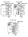
- FIG. 3A shows a cross-sectional microstructure of a coated Ni-base single crystal superalloy according to an embodiment of the present invention, after carrying out oxidation in air at 1150°C for 100 hr, or in air at 1100°C for one month.
- the coated sample was prepared by forming an alloy coating 16 on the surface of a Ni-base single crystal superalloy (substrate) 10 by electrodeposition in a molten salt and, on the surface of the alloy coating 16, TBC 54 compared of an undercoat 50 formed of an NiCoCrAlY alloy and a topcoat 52 formed of ZrO 2 .
- FIG. 3B shows a cross-sectional microstructure of a coated Ni-base single crystal superalloy illustrative of a further embodiment of the present invention, after carrying out oxidation in the same manner as described above in connection with FIG. 3A .
- the coated superalloy sample was prepared by sputtering a Re-Al alloy coating 26 on the surface of a Ni-base single crystal superalloy (substrate) 10 and forming, on the surface of the alloy coating 26, TBC 54 in the same manner as described above.
- FIG. 3C shows a cross-sectional microstructure, after oxidation in the same manner as described above, of a pure Ni-base single crystal superalloy (substrate) 10 on the surface of which TBC 54 has been directly formed.
- Table 2 Increase in weight, mg ⁇ cm -2 (a) Not more than 2 (b) 10 to 15 (c) Not less than 30
- (a) corresponds to a change in weight of the Ni-base single crystal superalloy shown in FIG. 3A
- the increase in weight was about one-fifteenth or less as compared with the Ni-base single crystal superalloy in which only TBC had been formed, indicating that the increase in weight due to oxidation was much smaller.
- Re is used as a high-melting metal
- Al is used as a metallic element for imparting corrosion resistance.
- the formation of an alloy coating composed Re-Cr-W-Al-Ni can improve the diffusion barrier function.
- the base metal is Re.
- Ni-base multi crystal superalloy may used instead of Ni-base single crystal superalloy.
- plating in a chloride-containing molten salt may be carried out in a fluoride-containing molten salt.
- an electrodeposition may be formed in a solution.
- plating may be carried out in a molten salt containing a first chloride or fluoride of Re and a second chloride or fluoride of at least one alloying element for imparting corrosion resistance, wherein an alloy of at least one metal contained in the first chloride or fluoride with at least one metal contained in the second chloride or fluoride is used as an electrode.
- a denser coating can be formed and, in addition, the composition of the coating can be easily controlled.
- plating may be carried out in a molten salt containing a first chloride or fluoride of Re and a second chloride or fluoride of at least one alloying element for imparting corrosion resistance, wherein at least one metal contained in the first chloride or fluoride and at least one metal contained in the second chloride or fluoride are used as electrodes for alternate or simultaneous plating.
- the composition and structure of the alloy coating can be controlled as desired.
- an alloy coating can be obtained which is stable at a high temperature of 1100°C or above, even at 1150°C or above, and possesses excellent oxidation resistance and, in addition, can inhibit the outward diffusion of metallic elements constituting the base (substrate) metal, such as Ni, Al, Ti, and Ta, and the inward diffusion of an oxidizing agent and the like. Further, the application of the alloy coating to members for high temperature apparatuses can provide highly heat-resistant and corrosion-resistant members with prolonged service life.
Description
- The present invention relates to an alloy coating for use as a surface coating which can prolong the service life of members for apparatuses for high temperature applications (hereinafter referred to as "members for high temperature apparatuses"), such as gas turbine blades, jet engines, and heat-transfer tubes for boilers, a method for forming the same, and a member for high temperature apparatuses.
- For members for high temperature apparatuses, such as industrial gas turbine blades and heat-transfer tubes for boilers, in many cases, a coating is applied on the surface thereof to improve the heat resistance and the corrosion resistance of the members. In general, in order to improve the heat resistance, a ceramic coating called "thermal barrier coating" (hereinafter referred to as "TBC") is applied to the surface of a substrate. Such a ceramic coating, however, has the problem that the difference in coefficient of thermal expansion between the substrate metal and the ceramic is so large that, when a ceramic layer is directly formed on the surface of the substrate, the ceramic layer is likely to be separated from the interface of the ceramic layer and the substrate. In order to solve this problem, in general, as shown in
FIG. 3C , anundercoat 50 formed of an alloy layer and atopcoat 52 formed of, for example, a ceramic such as ZrO2 are laminated in that order on the surface of thesubstrate 10, to improve the adhesion ofTBC 54 to thesubstrate 10. - Under very high-temperature environments of about 800 to 1200°C, however, as shown in
FIG. 3C , theundercoat 50 is reacted with thesubstrate 10 to form an Al-deficient layer 56 and alayer 58 of Al2O3 + NiAl2O4 having poor protective properties at the interface of theundercoat 50 and thesubstrate 10, thus resulting in deterioration ofTBC 54. Further, sinceTBC 54 is porous, atmosphere gas enters the inside ofTBC 54 and then internally oxidizes or internally nitrides thesubstrate 10 to form an internal corrosion layer containing aninternal oxide 36 and aninternal nitride 38 within thesubstrate 10. For this reason, the service life of the member for high temperature apparatuses is as short as several months. This is a severe problem involved such members having a conventional ceramic coating. In a prior art technique, an attempt has been made to use a Pt-Al spray coating after Pt plating, usually, to improve the heat resistance. This technique, however, cannot attain a satisfactory improvement. - On the other hand, in order to improve the corrosion resistance, coating techniques such as diffusion coating of Cr or A1 and spray coating of a high Ni-high Cr alloy have been utilized. Such coatings, however, have the drawback that when the coated member is used under a very high-temperature environment of about 800 to 1200°C, the element contributing to the corrosion resistance is very rapidly diffused and, in addition, is highly reactive. Thus, the protective coating cannot be maintained stably for a long period of time. Further, even in the temperature range of 500 to 800°C, when the member is used in a strongly corrosive environment containing, for example, chlorine (Cl) or sulfur (S), the element constituting the protective coating, such as Cr or Al, is rapidly consumed. Thus, again, the protective coating cannot be stably maintained for a long period of time, resulting in a short service life of the apparatus. For the above reasons, at the present time, the prolongation of the service life of a member for high temperature apparatuses is only made by lowering the service temperature of the apparatus while sacrificing the performance of the apparatus.
- As described above, in the case of members used at high temperatures, even when TBC is applied to the members to improve the heat resistance, the TBC layer is deteriorated as a result of a reaction of TBC with the substrate during use of the members, and, in addition, the substrate is internally oxidized or internally nitrided by atmosphere gas which has penetrated into the inside of the coating. Further, even with the application of the diffusion coating of Cr or Al, the spray coating of a high Ni-high Cr alloy, etc., for improving the corrosion resistance, when the apparatus is used under an environment containing Cl, S or the like, which is highly corrosive at high temperatures, the consumption rate of the element constituting the protective coating, such as Cr or Al, is so high that a stable protective coating cannot be maintained for a long period of time.
-
EP 0 848 071 describes a Ni-base alloy containing Re, W, Al, Cr for high temperature apparatuses. - It has now been found that rhenium (Re), iridium (Ir), niobium (Nb), tantalum (Ta), molybdenum (Mo), and tungsten (W), which are high-melting metals, when alloyed with an element for imparting corrosion resistance, such as chromium (Cr), aluminum (Al), silicon (Si), magnesium (Mg), niobium (Nb), tantalum (Ta), nickel (Ni), cobalt (Co), iron (Fe), molybdenum (Mo), iridium (Ir), tungsten (W), platinum (Pt), or rhodium (Rh), to form an alloy phase, are stable at a high temperature of 1100°C or above, even at 1150°C or above, and, at the same time, possess excellent oxidation resistance. Further, as a result of studies on a high temperature corrosion reaction of a Ni-base superalloy coated with a Re (Ir, Nb, Ta, Mo, and W) - X alloy (wherein X = Cr, Al, Si, Mg, Nb, Ta, Ni, Co, Fe, Mo, Pt, Rh, Ir, W or the like), it has been found that an alloy phase containing Re (Ir, Nb, Ta, Mo, and W) can inhibit the outward diffusion of Ni, Al, Ti, Ta or the like and the inward diffusion of an oxidizing agent or the like. Thus, it is expected that provision of a thin layer of this alloy based on Re (Ir, Nb, Ta, Mo, and W) on the surface of a substrate can realize the inhibition of the outward diffusion of the alloying element from the substrate and the inward diffusion of the oxidizing agent or the like from the environment, which has been unsatisfactory with the conventional Pt-A1 sprayed coating, leading to less corrosion and damage in the substrate whereby the service life of the member for high temperature apparatuses would be prolonged. Further, for members on which TBC is to be applied, when the above-described coating is interposed between the substrate and TBC, the interposed coating is considered to function as an excellent diffusion barrier which can inhibit the deterioration of TBC, caused by a reaction of TBC with the substrate, and the internal corrosion of the substrate.
- As coating techniques used for improving heat resistance and corrosion resistance, PVD, CVD and spray coating are known. These methods have the drawbacks that: ① control of the thickness and composition of the coating is difficult; ② a large coating apparatus is needed, and the operation is complicated; ③ the formed coating has many defects and cracks; ④ there is a number of limitations on the size and shape of a substrate to be coated (for example, coating faithfully conforming to the shape of concaves and convexes is difficult); and ⑤ the cost is high. In contrast, the technique of plating in a molten salt has the advantages that ① the thickness and composition of the coating can be easily controlled; ② the coating can be effected with ease by using a simple apparatus; ③ a dense coating having no significant defect can be formed; ④ there is few limitations on the size and shape of a substrate to be coated; and ⑤ the cost is low.
- The present invention has been accomplished under the above circumstances.
- It is therefore an object of the present invention to provide a member for high temperature apparatuses according to claim 1, to which an alloy coating has been applied.
- The alloy coating is formed by plating in a molten salt and comprises an alloy, said alloy comprising Re as a base member, and alloying elements Cr, Ni, W and Al for providing a corrosion resistance alloy with the base member.
- A deterioration in substrate caused by corrosion and damage can be reduced by virtue of the alloy coating, which can function as a better diffusion barrier, covering the surface of the substrate, whereby the service life of the member is prolonged.
- Here a thermal barrier coating may be formed on the surface of the alloy coating. In this case, a deterioration in thermal barrier coating, caused by the reaction of the thermal barrier coating with the substrate, and the penetration of atmosphere gas into the substrate can be prevented by virtue of the alloy coating, which can function as a better diffusion barrier, interposed between the substrate and the thermal barrier coating, whereby the service life of the member is prolonged.
- The above and other objects, features, and advantages of the present invention will be apparent from the following description when taken in conjunction with the accompanying drawings which illustrates preferred embodiments of the present invention by way of example.
-
-
FIGS. 1A to 1D are diagrams showing cross-sectional microstructures of Ni-base single crystal superalloys which, according to different embodiments of the present invention, have been covered with a Re-Al alloy coating by plating in a molten salt (FIGS. 1A and 1B ), by sputtering (FIG. 1C ), and by sputtering in combination with A1 vapor diffusion (FIG. 1D ); -
FIGS. 2A to 2E are diagrams showing cross-sectional microstructures of the coated Ni-base single crystal superalloys after carrying out oxidation in air at 1150°C for 100 hr, or in air at 1100°C for one month, whereinFIG. 2A represents the results of the experiment on the coated Ni-base single crystal superalloy shown inFIG. 1A ,FIG. 2B the results of the experiment on the coated Ni-base single crystal superalloy shown inFIG. 1B ,FIG. 2C the results of the experiment on the coated Ni-base single crystal superalloy shown inFIG. 1C ,FIG. 2D the results of the experiment on the coated Ni-base single crystal superalloy shown inFIG. 1D , andFIG. 2E the results of the experiment on a pure (uncoated) Ni-base single crystal superalloy; and -
FIGS. 3A to 3C are diagrams showing cross-sectional microstructures of Ni-base single crystal superalloys after carrying out oxidation in air at 1150°C for 100 hr, or in air at 1100°C for one month, whereinFIG. 3A represents the results of the experiment on a Ni-base single crystal superalloy, according to another embodiment of the present invention, wherein a Re-Al alloy coating formed by molten salt plating has been interposed between a substrate and TBC,FIG. 3B the results of the experiment on a Ni-base single crystal superalloy, wherein a Re-Al alloy coating formed by sputtering has been interposed between a substrate and TBC, andFIG. 3C the results of the experiment on a Ni-base single crystal superalloy wherein TBC has been formed directly on the surface of a substrate. - Illustrating embodiments of the present invention will be described with reference to the accompanying drawings. In these embodiments, Re is used as a high-melting metal, and Al as a metallic element for imparting corrosion resistance.
-
FIGS. 1A and 1B show cross-sectional microstructures of Ni-base single crystal superalloys (Ni-Co-Cr-Al-W-Ta-Ti-Re-Mo alloy) having a coating, illustrative of different embodiments of the present invention, which can be used as a member for high temperature apparatuses. More specifically,FIG. 1A shows a coated Ni-base single crystal superalloy composed of a Ni-base single crystal superalloy (substrate) 10 and analloy coating 16 covering the surface of thesubstrate 10, thealloy coating 16 being composed of a mixture of a Ni-Al alloy 12 with aRe-Al alloy 14.FIG. 1B shows a coated Ni-base single crystal superalloy composed of asubstrate 10 and analloy coating 16 covering the surface of thesubstrate 10, thealloy coating 16 being composed of aRe-Al alloy layer 18 and a Ni-Al alloy layer 20. In this case, Cr, W, and Ni diffused from thesubstrate 10 are contained in the Re-Al alloy layer, and an Al diffusedlayer 22 is formed at the interface between thesubstrate 10 and thealloy coating 16. - The coated Ni-base single crystal superalloys having cross-sectional microstructures shown in
FIGS. 1A and 1B were prepared by coating the surface of the Ni-base single crystal superalloy (substrate) 10 with a Re-Al alloy by plating in a molten salt. More specifically, in the preparation of the coated Ni-base single crystal superalloy shown inFIG. 1A , Al and Re were reacted with chlorine gas in an LiCl-KCl eutectic salt to produce AlCl3 and ReCl4 dissolved and absorbed directly in the LiCl-KCl molten salt, and this was used as the molten salt, and the surface of thesubstrate 10 was plated in the molten salt under the conditions of plating temperature 500°C, current 10 mA, and platingtime 10 hr. The coated Ni-base single crystal superalloy shown inFIG. 1B was prepared by plating thesubstrate 10 in the same manner as described above in connection withFIG. 1A , except that the plating temperature was changed to 700°C. -
FIG. 1C shows a cross-sectional microstructure of a coated Ni-base single crystal superalloy illustrative of another embodiment of the present invention, wherein the surface of thesubstrate 10 has been coated with aRe-Al alloy coating 26 by sputtering.FIG. 1D shows a cross-sectional microstructure of a coated Ni-base single crystal superalloy, wherein the surface of thesubstrate 10 has been coated with a Re-Al alloy coating by sputtering, followed by Al vapor diffusion. As can be seen fromFIG. 1D , the formation of a Re-Al alloy coating by sputtering followed by Al vapor diffusion results in the formation of a laminated structure of a Re-Al-(Cr-W-Ni)alloy layer 18 and a Ni-Al alloy layer 20, as with the structure shown inFIG. 1B . Further, the formation of an A1 diffusedlayer 22 is also observed at the substrate/coating interface. FromFIGS. 1A to 1D , it is apparent that, when sputtering is solely adopted, the formedRe-Al alloy coating 26 havemany cracks 26a (seeFIG. 1C ), whereas, when plating with an alloy in a molten salt is adopted, a denseRe-Al alloy coating 16 substantially free from cracks and defects can be formed (seeFIGS. 1A and 1B ). Further, it is apparent that, even when the alloy coating has been formed by sputtering, the subsequent Al vapor diffusion treatement can vanish the cracks. -
FIGS. 2A to 2E show cross-sectional microstructures, after carrying out oxidation in air at 1150°C for 100 hr or in air at 1100°C for one month, of the coated Ni-base single crystal superalloys having the cross-sectional microstructrues shown inFIGS. 1A to 1D and a pure Ni-base single crystal superalloy not subjected to surface treatment (coating), whereinFIG. 2A corresponds to the coated superalloy shown inFIG. 1A ,FIG. 2B the coated superalloy shown inFIG. 1B ,FIG. 2C the coated superalloy shown inFIG. 1C ,FIG. 2D the coated superalloy shown inFIG. 1D , andFIG. 2E the pure Ni-base single crystal superalloy having no coating. - In the case of the pure Ni-base single crystal superalloy not subjected to surface treatment (
FIG. 2E ), athick oxide scale 34 composed of aninner layer 30 formed of Al2O3 + Cr2O3 and anouter layer 32 formed of NiAl2O4 + NiO containing Ti and Ta was formed on the surface of thesubstrate 10 during the oxidation test. It is thus apparent that Cr, Ni, Ti, and Ta contained in thesubstrate 10 were outwardly diffused to form anoxide scale 34 having poor protective properties. Further, an internal corrosion product layer containing a discreteinternal oxide 36 and aninternal nitride 38 was formed within thesubstrate 10, indicating that oxygen and nitrogen in the gaseous phase were diffused into thesubstrate 10 to cause the internal oxidation and internal nitriding of thesubstrate 10. - In the case of the Ni-base single crystal superalloy having a single Re-Al alloy coating layer formed by sputtering (
FIG. 2C ), it is apparent that, as in the case of the pure Ni-base single crystal superalloy, an internal corrosion product layer, containing aninternal oxide 36 and aninternal nitride 38, and anoxide scale 34 composed of aninner layer 30 of Al2O3 + Cr2O3 and anouter layer 32 of NiAl2O4 + NiO were produced but locally with a reduced thickness. It is considered in this regard that, although the Re-Al alloy coating per se formed by sputtering has good heat and corrosion resistance, the presence ofcracks 26a as shown inFIG. 1C , in theRe-Al alloy coating 26 allows the metallic elements and gas to diffuse through thecracks 26a and thus allows the oxidation to proceed. When an alloy coating illustrative of the present invention is to be formed by sputtering, reducing the thickness of the alloy coating, that is, the formation of a thin alloy coating, to reduce the creation of cracks will improve the heat resistance and the corrosion resistance. On the other hand, when both sputtering and Al vapor diffusion were carried out to form the alloy coating (FIG. 2D ), unlike the case of sputtering alone, there was no crack and, a thin and substantially impurity-free Al2O3 layer 40 was formed on the surface of the alloy coating during the high-temperature oxidation test. Thus, sputtering followed by Al vapor diffusion results in the formation of a dense coating having no significant cracking to improve the corrosion resistance. - In the case of the Ni-base single crystal superalloys which had been coated with a Re-Al alloy by plating in a molten salt (
FIGS. 2A and 2B ), a thin Al2O3 layer 40 free from Cr and Ni was formed on the surface of thealloy coating 16, indicating that the elements contained in thesubstrate 10 were not diffused through thealloy coating 16 into the outside of thecoating 16. Further, there was no evidence indicating that thesubstrate 10 was internally oxidized or internally nitrided. The above test results show that the Ni-base single crystal superalloys, which have been coated with aRe-Al alloy coating 16 by plating in a molten salt, have much improved heat resistance and corrosion resistance compared to the pure Ni-base single crystal superalloy and the Ni-base single crystal superalloy on which aRe-Al alloy coating 26 has been sputtered. - A change in weight after the oxidation test in air at 1150°C for 100 hr, or in air at 1100°C for one month from the original weight before the oxidation test is shown in Table 1.
Table 1 Increase in weight, mg·cm-2 (a) Not more than 2 (b) Not more than 2 (c) 10 to 20 (d) Not more than 2 (e) Not less than 40 - In Table 1, (a) corresponds to a change in weight of the coated Ni-base single crystal superalloy shown in
FIG. 2A , (b) a change in weight of the coated Ni-base single crystal superalloy shown inFIG. 2B , (c) a change in weight of the coated Ni-base single crystal superalloy shown inFIG. 2C , (d) a change in weight of the coated Ni-base single crystal superalloy shown inFIG. 2D , and (e) a change in weight of the pure (uncoated) Ni-base single crystal superalloy shown inFIG. 2E . - As is apparent from Table 1, for the pure Ni-base single crystal superalloy ((e) in Table 1), there was an increase in weight of not less than 40 mg·cm-2, whereas, for the Ni-base single crystal superalloy which had been coated with a Re-Al alloy by sputtering ((c) in Table 1), the increase in weight was reduced by about 50% or more as compared with the pure Ni-base single crystal superalloy, indicating that the latter has an improved heat resistance and corrosion resistance. For the Ni-base single crystal superalloy which had been subjected to sputtering + Al vapor diffusion ((d) in Table 1), and for the Ni-base single crystal superalloys coated with a Re-Al alloy by plating in a molten salt ((a) and (b) in Table 1), the increase in weight was reduced to about one-twentieth as compound with the pure Ni-base single crystal superalloy, indicating that the increase in weight due to oxidation was much smaller.
-
FIG. 3A shows a cross-sectional microstructure of a coated Ni-base single crystal superalloy according to an embodiment of the present invention, after carrying out oxidation in air at 1150°C for 100 hr, or in air at 1100°C for one month. The coated sample was prepared by forming analloy coating 16 on the surface of a Ni-base single crystal superalloy (substrate) 10 by electrodeposition in a molten salt and, on the surface of thealloy coating 16,TBC 54 compared of anundercoat 50 formed of an NiCoCrAlY alloy and atopcoat 52 formed of ZrO2. -
FIG. 3B shows a cross-sectional microstructure of a coated Ni-base single crystal superalloy illustrative of a further embodiment of the present invention, after carrying out oxidation in the same manner as described above in connection withFIG. 3A . The coated superalloy sample was prepared by sputtering aRe-Al alloy coating 26 on the surface of a Ni-base single crystal superalloy (substrate) 10 and forming, on the surface of thealloy coating 26,TBC 54 in the same manner as described above. For comparison,FIG. 3C shows a cross-sectional microstructure, after oxidation in the same manner as described above, of a pure Ni-base single crystal superalloy (substrate) 10 on the surface of whichTBC 54 has been directly formed. - As can be seen from
FIG. 3C , for the Ni-base single crystal superalloy on which only TBC 54 has been directly formed, the formation of aninternal oxide 36 and aninternal nitride 38 within thesubstrate 10 was observed. Further, the formation of an Al-deficient layer 56 and alayer 58 of Al2O3 + NiAl2O4 having poor protective properties at the interface betweenTBC 54 and thesubstrate 10 was also observed. This shows the progress of deterioration inTBC 54 from the interface betweenTBC 54 and thesubstrate 10.Numeral 60 designates Al2O3, and numeral 62 an NiAl2O4 layer. - On the other hand, as shown in
FIG. 3B , for the Ni-base single crystal superalloy in which aRe-Al alloy coating 26 had been sputtered so as to be interposed between thesubstrate 10 and TBC 54 (FIG. 3B ), as with the case of the formation ofTBC 54 alone, an internal corrosion product layer, an Al-deficient layer 56, and alayer 58 of Al2O3 + NiAl2O4 having poor protective properties were produced, but locally with a reduced thickness. It may be that, as with the case of the superalloy shown inFIG. 2C , the corrosion progressed through defects such as cracks created in the coating, although the Re-Al alloy coating per se has good corrosion resistance. - In contrast, for the Ni-base single crystal superalloy shown in
FIG. 3A in which aRe-Al alloy coating 16 formed by plating in a molten salt has been interposed between thesubstrate 10 andTBC 54, there was no evidence of the internal corrosion of thesubstrate 10 and a dense and thin Al2O3continuous layer 64 was formed at the interface betweenTBC 54 and thesubstrate 10. The concentration of other elements (such as Ni, Ti, and Ta) in the Al2O3continuous layer 64 was substantially 0 (zero). There was no evidence of the formation of an Al-deficient layer and a layer of Al2O3 + NiAl2O4 having poor protective properties. These facts show that the interposition of theRe-Al alloy coating 16 formed by plating in a molten salt between thesubstrate 10 andTBC 54 in a Ni-base single crystal superalloy significantly improves the oxidation resistance of thesubstrate 10 and, at the same time, inhibits the deterioration inTBC 54. - A change in weight after the oxidation in air at 1150°C for 100 hr, or in air at 1100°C for one month from the original weight before the oxidation test is shown in Table 2.
Table 2 Increase in weight, mg·cm-2 (a) Not more than 2 (b) 10 to 15 (c) Not less than 30 - In Table 2, (a) corresponds to a change in weight of the Ni-base single crystal superalloy shown in
FIG. 3A , (b) a change in weight of the Ni-base single crystal superalloy shown inFIG. 3B , and (c) a change in weight of the Ni-base single crystal superalloy shown inFIG. 3C . - As is apparent from this table 2, for the Ni-base single crystal superalloy in which only TBC had been formed ((c) in Table 2), there was an increase in weight of not less than 30 mg·cm-2. On the other hand, the Ni-base single crystal superalloy in which a
Re-Al alloy coating 26 had been sputtered so as to be interposed between thesubstrate 10 and TBC 54 ((b) in Table 2), the increase in weight was reduced by about 50% or more as compared with the Ni-base single crystal superalloy in which only TBC had been formed. Further, for the Ni-base single crystal superalloy in which aRe-Al alloy coating 16 formed by plating in a molten salt was interposed between thesubstrate 10 and TBC 54 ((a) in Table 2), the increase in weight was about one-fifteenth or less as compared with the Ni-base single crystal superalloy in which only TBC had been formed, indicating that the increase in weight due to oxidation was much smaller. - The above test results show that when a Re-Al alloy coating formed by plating in a molten salt (or a Re-Al alloy coating formed by sputtering + Al vapor diffusion) is provided on the surface of the substrate, or alternatively, is interposed between TBC and the substrate, the heat resistance and corrosion resistance of a member for apparatuses can be significantly improved to thereby prolong the service life of the member.
- In the above embodiments, Re is used as a high-melting metal, and Al is used as a metallic element for imparting corrosion resistance. Further, the formation of an alloy coating composed Re-Cr-W-Al-Ni, can improve the diffusion barrier function. When the alloy coating is formed by electrodeposition in a molten salt, the base metal is Re. Ni-base multi crystal superalloy may used instead of Ni-base single crystal superalloy.
- Although plating in a chloride-containing molten salt has been described above, plating may be carried out in a fluoride-containing molten salt. In some elements, an electrodeposition may be formed in a solution.
- Further, plating may be carried out in a molten salt containing a first chloride or fluoride of Re and a second chloride or fluoride of at least one alloying element for imparting corrosion resistance, wherein an alloy of at least one metal contained in the first chloride or fluoride with at least one metal contained in the second chloride or fluoride is used as an electrode. According to this embodiment, since plating can be stably carried out for a long period of time, a denser coating can be formed and, in addition, the composition of the coating can be easily controlled.
- Further, plating may be carried out in a molten salt containing a first chloride or fluoride of Re and a second chloride or fluoride of at least one alloying element for imparting corrosion resistance, wherein at least one metal contained in the first chloride or fluoride and at least one metal contained in the second chloride or fluoride are used as electrodes for alternate or simultaneous plating. According to this embodiment, the composition and structure of the alloy coating can be controlled as desired.
- As described above, according to the present invention, an alloy coating can be obtained which is stable at a high temperature of 1100°C or above, even at 1150°C or above, and possesses excellent oxidation resistance and, in addition, can inhibit the outward diffusion of metallic elements constituting the base (substrate) metal, such as Ni, Al, Ti, and Ta, and the inward diffusion of an oxidizing agent and the like. Further, the application of the alloy coating to members for high temperature apparatuses can provide highly heat-resistant and corrosion-resistant members with prolonged service life.
Claims (2)
- (Amended) A member for high temperature apparatuses, comprising a substrate and an alloy coating covering the surface of the substrate formed by plating in a molten salt, said alloy coating comprising an alloy, said alloy comprising:Re as a base member, andalloying elements Cr, Ni, W and A1 for providing a corrosion resistance alloy with the base member.
- The member for high temperature apparatuses according to claim 1, further comprising a thermal barrier coating on the surface of the alloy coating.
Applications Claiming Priority (2)
| Application Number | Priority Date | Filing Date | Title |
|---|---|---|---|
| JP2000062613 | 2000-03-07 | ||
| JP2000062613 | 2000-03-07 |
Publications (3)
| Publication Number | Publication Date |
|---|---|
| EP1132499A2 EP1132499A2 (en) | 2001-09-12 |
| EP1132499A3 EP1132499A3 (en) | 2004-02-25 |
| EP1132499B1 true EP1132499B1 (en) | 2010-05-19 |
Family
ID=18582598
Family Applications (1)
| Application Number | Title | Priority Date | Filing Date |
|---|---|---|---|
| EP01105658A Expired - Lifetime EP1132499B1 (en) | 2000-03-07 | 2001-03-07 | Alloy coating, method for forming the same, and member for high temperature apparatuses |
Country Status (4)
| Country | Link |
|---|---|
| US (2) | US6830827B2 (en) |
| EP (1) | EP1132499B1 (en) |
| JP (1) | JP2001323332A (en) |
| DE (1) | DE60142138D1 (en) |
Families Citing this family (30)
| Publication number | Priority date | Publication date | Assignee | Title |
|---|---|---|---|---|
| JP5295474B2 (en) * | 2000-09-28 | 2013-09-18 | 敏夫 成田 | Niobium-based alloy heat-resistant material |
| JP4047115B2 (en) | 2002-09-13 | 2008-02-13 | アルプス電気株式会社 | Soft magnetic film, thin film magnetic head using the soft magnetic film, and method for manufacturing the soft magnetic film |
| US7466799B2 (en) * | 2003-04-09 | 2008-12-16 | Varian Medical Systems, Inc. | X-ray tube having an internal radiation shield |
| US6933052B2 (en) * | 2003-10-08 | 2005-08-23 | General Electric Company | Diffusion barrier and protective coating for turbine engine component and method for forming |
| US7851070B2 (en) * | 2004-01-15 | 2010-12-14 | National University Corporation Hokkaido University | Diffusion barrier alloy film and high-temperature apparatus member |
| US7778422B2 (en) * | 2004-02-27 | 2010-08-17 | Microsoft Corporation | Security associations for devices |
| US20060165547A1 (en) * | 2005-01-26 | 2006-07-27 | Honeywell International, Inc. | High strength rhenium alloys and high temperature components made from such alloys |
| DE102005011011A1 (en) * | 2005-03-10 | 2006-09-14 | Mtu Aero Engines Gmbh | Component, in particular gas turbine component |
| US8221901B2 (en) * | 2005-03-28 | 2012-07-17 | National Institute For Materials Science | Material for heat resistant component |
| US20070116890A1 (en) * | 2005-11-21 | 2007-05-24 | Honeywell International, Inc. | Method for coating turbine engine components with rhenium alloys using high velocity-low temperature spray process |
| JP4716328B2 (en) * | 2006-07-05 | 2011-07-06 | 財団法人電力中央研究所 | Life management method of thermal barrier coating |
| JP5146867B2 (en) * | 2006-08-18 | 2013-02-20 | 独立行政法人物質・材料研究機構 | Heat resistant material with excellent high temperature durability |
| WO2008032806A1 (en) | 2006-09-13 | 2008-03-20 | National Institute For Materials Science | Heat resistant member |
| US8388890B2 (en) | 2006-09-21 | 2013-03-05 | Tyco Electronics Corporation | Composition and method for applying an alloy having improved stress relaxation resistance |
| WO2008059971A1 (en) | 2006-11-16 | 2008-05-22 | National University Corporation Hokkaido University | Multilayer alloy coating film, heat-resistant metal member having the same, and method for producing multilayer alloy coating film |
| JP4896702B2 (en) * | 2006-12-22 | 2012-03-14 | 株式会社ディ・ビー・シー・システム研究所 | Alloy film, method for producing alloy film, and heat-resistant metal member |
| CN101168815B (en) * | 2007-12-05 | 2010-06-02 | 北京航空航天大学 | Sheet layer niobium-molybdenum-silicon-base in situ composite material and preparation method thereof |
| US8361178B2 (en) * | 2008-04-21 | 2013-01-29 | Smith International, Inc. | Tungsten rhenium compounds and composites and methods for forming the same |
| RU2463390C1 (en) * | 2008-09-29 | 2012-10-10 | Уильям Д. ХУРСТ | Method of metallisation and device for its realisation |
| US8367160B2 (en) * | 2010-11-05 | 2013-02-05 | United Technologies Corporation | Coating method for reactive metal |
| RU2566697C2 (en) * | 2011-04-13 | 2015-10-27 | Роллс-Ройс Корпорейшн | Interfacial diffusion barrier layer including iridium on metallic substrate |
| GB201109533D0 (en) * | 2011-06-08 | 2011-07-20 | Rolls Royce Plc | Temperature indicating paint |
| CN102650064A (en) * | 2012-05-23 | 2012-08-29 | 深圳市新星轻合金材料股份有限公司 | Potassium cryolite used for aluminum electrolysis industry and preparation method for potassium cryolite |
| JP5936487B2 (en) * | 2012-08-23 | 2016-06-22 | キヤノン株式会社 | Amorphous alloy, molding die, and optical element manufacturing method |
| EP2918705B1 (en) | 2014-03-12 | 2017-05-03 | Rolls-Royce Corporation | Coating including diffusion barrier layer including iridium and oxide layer and method of coating |
| CN106853436B (en) * | 2016-12-29 | 2020-05-19 | 宁夏东方钽业股份有限公司 | Molybdenum-based composite coating and preparation method thereof |
| CN108914053B (en) * | 2018-07-20 | 2020-04-28 | 中国人民解放军国防科技大学 | Method for preparing ultrahigh-temperature coating by in-situ diffusion modification of iridium coating |
| WO2021070529A1 (en) * | 2019-10-07 | 2021-04-15 | 昭和電工株式会社 | Corrosion-resistant member |
| CN113281243A (en) * | 2021-05-21 | 2021-08-20 | 北京航空航天大学 | High-throughput characterization method for corrosion behavior of gradient Al-Cr coating on novel Co-Al-W-based alloy |
| CN114574834A (en) * | 2021-12-02 | 2022-06-03 | 贵研铂业股份有限公司 | Ta-Re layered composite material and preparation method and application thereof |
Citations (1)
| Publication number | Priority date | Publication date | Assignee | Title |
|---|---|---|---|---|
| EP0848071A1 (en) * | 1996-12-11 | 1998-06-17 | United Technologies Corporation | Superalloy compositions |
Family Cites Families (22)
| Publication number | Priority date | Publication date | Assignee | Title |
|---|---|---|---|---|
| GB385859A (en) * | 1931-06-22 | 1933-01-05 | Siebert G M B H G | Improvements relating to catalytic reactions and catalysts for use therein |
| FR1385594A (en) * | 1963-02-18 | 1965-01-15 | Union Carbide Corp | Electrolytic deposition of refractory metals |
| DE1771763A1 (en) * | 1967-07-03 | |||
| US4517253A (en) * | 1984-01-23 | 1985-05-14 | Rose Robert M | Cryoelectrodeposition |
| JPS6199925A (en) * | 1984-10-19 | 1986-05-19 | Nec Corp | Magnetic storage medium and its production |
| JPS61144025A (en) * | 1984-12-18 | 1986-07-01 | Matsushita Electric Ind Co Ltd | Manufacture of semiconductor device |
| US4731253A (en) * | 1987-05-04 | 1988-03-15 | Wall Colmonoy Corporation | Wear resistant coating and process |
| US5273712A (en) * | 1989-08-10 | 1993-12-28 | Siemens Aktiengesellschaft | Highly corrosion and/or oxidation-resistant protective coating containing rhenium |
| US5395221A (en) * | 1993-03-18 | 1995-03-07 | Praxair S.T. Technology, Inc. | Carbide or boride coated rotor for a positive displacement motor or pump |
| US5427866A (en) | 1994-03-28 | 1995-06-27 | General Electric Company | Platinum, rhodium, or palladium protective coatings in thermal barrier coating systems |
| US5556713A (en) | 1995-04-06 | 1996-09-17 | Southwest Research Institute | Diffusion barrier for protective coatings |
| GB9612811D0 (en) | 1996-06-19 | 1996-08-21 | Rolls Royce Plc | A thermal barrier coating for a superalloy article and a method of application thereof |
| DE69708541T2 (en) | 1996-07-23 | 2002-05-08 | Rolls Royce Plc | Process for aluminizing a superalloy |
| US5817371A (en) | 1996-12-23 | 1998-10-06 | General Electric Company | Thermal barrier coating system having an air plasma sprayed bond coat incorporating a metal diffusion, and method therefor |
| US6143141A (en) * | 1997-09-12 | 2000-11-07 | Southwest Research Institute | Method of forming a diffusion barrier for overlay coatings |
| DE69732046T2 (en) * | 1997-10-30 | 2005-12-08 | Alstom | PROTECTIVE COATING FOR HIGH TEMPERATURE |
| GB9724844D0 (en) * | 1997-11-26 | 1998-01-21 | Rolls Royce Plc | A coated superalloy article and a method of coating a superalloy article |
| JPH11350196A (en) * | 1998-06-12 | 1999-12-21 | C Uyemura & Co Ltd | Bn composite nickel-tungsten alloy film, its formation and piston ring |
| US6168875B1 (en) * | 1998-10-02 | 2001-01-02 | Asea Brown Boveri Ag | Coatings for turbine components |
| US6004372A (en) * | 1999-01-28 | 1999-12-21 | Praxair S.T. Technology, Inc. | Thermal spray coating for gates and seats |
| US6306524B1 (en) | 1999-03-24 | 2001-10-23 | General Electric Company | Diffusion barrier layer |
| US6207297B1 (en) * | 1999-09-29 | 2001-03-27 | Siemens Westinghouse Power Corporation | Barrier layer for a MCrAlY basecoat superalloy combination |
-
2001
- 2001-03-06 US US09/799,036 patent/US6830827B2/en not_active Expired - Fee Related
- 2001-03-07 EP EP01105658A patent/EP1132499B1/en not_active Expired - Lifetime
- 2001-03-07 JP JP2001063686A patent/JP2001323332A/en active Pending
- 2001-03-07 DE DE60142138T patent/DE60142138D1/en not_active Expired - Lifetime
-
2004
- 2004-05-06 US US10/839,161 patent/US6899926B2/en not_active Expired - Fee Related
Patent Citations (1)
| Publication number | Priority date | Publication date | Assignee | Title |
|---|---|---|---|---|
| EP0848071A1 (en) * | 1996-12-11 | 1998-06-17 | United Technologies Corporation | Superalloy compositions |
Also Published As
| Publication number | Publication date |
|---|---|
| US6899926B2 (en) | 2005-05-31 |
| US20010026877A1 (en) | 2001-10-04 |
| JP2001323332A (en) | 2001-11-22 |
| EP1132499A2 (en) | 2001-09-12 |
| US6830827B2 (en) | 2004-12-14 |
| DE60142138D1 (en) | 2010-07-01 |
| EP1132499A3 (en) | 2004-02-25 |
| US20050079089A1 (en) | 2005-04-14 |
Similar Documents
| Publication | Publication Date | Title |
|---|---|---|
| EP1132499B1 (en) | Alloy coating, method for forming the same, and member for high temperature apparatuses | |
| EP1463846B1 (en) | Mcraly bond coating and method of depositing said mcraly bond coating | |
| US6528189B1 (en) | Article with a protective coating system including an improved anchoring layer and method of manufacturing the same | |
| US6255001B1 (en) | Bond coat for a thermal barrier coating system and method therefor | |
| US6168874B1 (en) | Diffusion aluminide bond coat for a thermal barrier coating system and method therefor | |
| EP0979881B1 (en) | Thermal barrier and overlay coating systems comprising composite metal/metal oxide bond coating layers | |
| JP4855610B2 (en) | Oxidation resistant coating, related articles and methods | |
| EP1522608A2 (en) | Diffusion barrier and protective coating for turbine engine component and method for forming | |
| US20050238893A1 (en) | Highly oxidation resistant component | |
| US6458473B1 (en) | Diffusion aluminide bond coat for a thermal barrier coating system and method therefor | |
| US20100068556A1 (en) | Diffusion barrier layer and methods of forming | |
| EP1254967A1 (en) | Improved plasma sprayed thermal bond coat system | |
| US6387541B1 (en) | Titanium article having a protective coating and a method of applying a protective coating to a Titanium article | |
| EP1111091A1 (en) | Method of forming an active-element containing aluminide as stand alone coating and as bond coat and coated article | |
| US7138189B2 (en) | Heat-resistant Ti alloy material excellent in resistance to corrosion at high temperature and to oxidation | |
| EP1908857A2 (en) | Method for forming a thermal barrier coating | |
| EP1411148A1 (en) | Method of depositing a MCrALY-coating on an article and the coated article | |
| EP0985745B1 (en) | Bond coat for a thermal barrier coating system | |
| EP1008672A1 (en) | Platinum modified diffusion aluminide bond coat for a thermal barrier coating system | |
| Pytel et al. | Structure of Pd-Zr and Pt-Zr modified aluminide coatings deposited by a CVD method on nickel superalloys. | |
| EP1491659B1 (en) | A method of depositing a coating system | |
| EP1491650A1 (en) | A method of depositing a coating system | |
| US20030211245A1 (en) | Fabrication of an article having a thermal barrier coating system, and the article |
Legal Events
| Date | Code | Title | Description |
|---|---|---|---|
| PUAI | Public reference made under article 153(3) epc to a published international application that has entered the european phase |
Free format text: ORIGINAL CODE: 0009012 |
|
| AK | Designated contracting states |
Kind code of ref document: A2 Designated state(s): AT BE CH CY DE DK ES FI FR GB GR IE IT LI LU MC NL PT SE TR |
|
| AX | Request for extension of the european patent |
Free format text: AL;LT;LV;MK;RO;SI |
|
| PUAL | Search report despatched |
Free format text: ORIGINAL CODE: 0009013 |
|
| RIC1 | Information provided on ipc code assigned before grant |
Ipc: 7C 25D 3/66 A Ipc: 7C 25D 3/54 B Ipc: 7H 01L 21/302 B Ipc: 7C 23C 30/00 B |
|
| RIC1 | Information provided on ipc code assigned before grant |
Ipc: 7C 25D 3/66 A Ipc: 7C 25D 3/54 B |
|
| AK | Designated contracting states |
Kind code of ref document: A3 Designated state(s): AT BE CH CY DE DK ES FI FR GB GR IE IT LI LU MC NL PT SE TR |
|
| AX | Request for extension of the european patent |
Extension state: AL LT LV MK RO SI |
|
| 17P | Request for examination filed |
Effective date: 20040823 |
|
| AKX | Designation fees paid |
Designated state(s): DE FR GB |
|
| 17Q | First examination report despatched |
Effective date: 20041122 |
|
| 17Q | First examination report despatched |
Effective date: 20041122 |
|
| GRAP | Despatch of communication of intention to grant a patent |
Free format text: ORIGINAL CODE: EPIDOSNIGR1 |
|
| RIN1 | Information on inventor provided before grant (corrected) |
Inventor name: MIYASAKA, MATSUHO Inventor name: YAKUWA, HIROSHI Inventor name: NARITA, TOSHIO Inventor name: HAYASHI, SHIGENARI Inventor name: NOGUCHI, MANABU |
|
| GRAS | Grant fee paid |
Free format text: ORIGINAL CODE: EPIDOSNIGR3 |
|
| GRAA | (expected) grant |
Free format text: ORIGINAL CODE: 0009210 |
|
| AK | Designated contracting states |
Kind code of ref document: B1 Designated state(s): DE FR GB |
|
| REG | Reference to a national code |
Ref country code: GB Ref legal event code: FG4D |
|
| REF | Corresponds to: |
Ref document number: 60142138 Country of ref document: DE Date of ref document: 20100701 Kind code of ref document: P |
|
| PLBE | No opposition filed within time limit |
Free format text: ORIGINAL CODE: 0009261 |
|
| STAA | Information on the status of an ep patent application or granted ep patent |
Free format text: STATUS: NO OPPOSITION FILED WITHIN TIME LIMIT |
|
| 26N | No opposition filed |
Effective date: 20110222 |
|
| REG | Reference to a national code |
Ref country code: DE Ref legal event code: R097 Ref document number: 60142138 Country of ref document: DE Effective date: 20110221 |
|
| REG | Reference to a national code |
Ref country code: FR Ref legal event code: PLFP Year of fee payment: 16 |
|
| PGFP | Annual fee paid to national office [announced via postgrant information from national office to epo] |
Ref country code: DE Payment date: 20160302 Year of fee payment: 16 |
|
| PGFP | Annual fee paid to national office [announced via postgrant information from national office to epo] |
Ref country code: GB Payment date: 20160302 Year of fee payment: 16 Ref country code: FR Payment date: 20160208 Year of fee payment: 16 |
|
| REG | Reference to a national code |
Ref country code: DE Ref legal event code: R119 Ref document number: 60142138 Country of ref document: DE |
|
| GBPC | Gb: european patent ceased through non-payment of renewal fee |
Effective date: 20170307 |
|
| REG | Reference to a national code |
Ref country code: FR Ref legal event code: ST Effective date: 20171130 |
|
| PG25 | Lapsed in a contracting state [announced via postgrant information from national office to epo] |
Ref country code: FR Free format text: LAPSE BECAUSE OF NON-PAYMENT OF DUE FEES Effective date: 20170331 Ref country code: DE Free format text: LAPSE BECAUSE OF NON-PAYMENT OF DUE FEES Effective date: 20171003 |
|
| PG25 | Lapsed in a contracting state [announced via postgrant information from national office to epo] |
Ref country code: GB Free format text: LAPSE BECAUSE OF NON-PAYMENT OF DUE FEES Effective date: 20170307 |