EP1132585A2 - Emission control system - Google Patents
Emission control system Download PDFInfo
- Publication number
- EP1132585A2 EP1132585A2 EP01301005A EP01301005A EP1132585A2 EP 1132585 A2 EP1132585 A2 EP 1132585A2 EP 01301005 A EP01301005 A EP 01301005A EP 01301005 A EP01301005 A EP 01301005A EP 1132585 A2 EP1132585 A2 EP 1132585A2
- Authority
- EP
- European Patent Office
- Prior art keywords
- exhaust
- exhaust aftertreatment
- aftertreatment device
- stream additive
- exhaust stream
- Prior art date
- Legal status (The legal status is an assumption and is not a legal conclusion. Google has not performed a legal analysis and makes no representation as to the accuracy of the status listed.)
- Withdrawn
Links
Images


Classifications
-
- F—MECHANICAL ENGINEERING; LIGHTING; HEATING; WEAPONS; BLASTING
- F01—MACHINES OR ENGINES IN GENERAL; ENGINE PLANTS IN GENERAL; STEAM ENGINES
- F01N—GAS-FLOW SILENCERS OR EXHAUST APPARATUS FOR MACHINES OR ENGINES IN GENERAL; GAS-FLOW SILENCERS OR EXHAUST APPARATUS FOR INTERNAL COMBUSTION ENGINES
- F01N3/00—Exhaust or silencing apparatus having means for purifying, rendering innocuous, or otherwise treating exhaust
- F01N3/08—Exhaust or silencing apparatus having means for purifying, rendering innocuous, or otherwise treating exhaust for rendering innocuous
- F01N3/10—Exhaust or silencing apparatus having means for purifying, rendering innocuous, or otherwise treating exhaust for rendering innocuous by thermal or catalytic conversion of noxious components of exhaust
- F01N3/18—Exhaust or silencing apparatus having means for purifying, rendering innocuous, or otherwise treating exhaust for rendering innocuous by thermal or catalytic conversion of noxious components of exhaust characterised by methods of operation; Control
- F01N3/20—Exhaust or silencing apparatus having means for purifying, rendering innocuous, or otherwise treating exhaust for rendering innocuous by thermal or catalytic conversion of noxious components of exhaust characterised by methods of operation; Control specially adapted for catalytic conversion ; Methods of operation or control of catalytic converters
- F01N3/2066—Selective catalytic reduction [SCR]
- F01N3/208—Control of selective catalytic reduction [SCR], e.g. dosing of reducing agent
-
- F—MECHANICAL ENGINEERING; LIGHTING; HEATING; WEAPONS; BLASTING
- F01—MACHINES OR ENGINES IN GENERAL; ENGINE PLANTS IN GENERAL; STEAM ENGINES
- F01N—GAS-FLOW SILENCERS OR EXHAUST APPARATUS FOR MACHINES OR ENGINES IN GENERAL; GAS-FLOW SILENCERS OR EXHAUST APPARATUS FOR INTERNAL COMBUSTION ENGINES
- F01N9/00—Electrical control of exhaust gas treating apparatus
- F01N9/005—Electrical control of exhaust gas treating apparatus using models instead of sensors to determine operating characteristics of exhaust systems, e.g. calculating catalyst temperature instead of measuring it directly
-
- F—MECHANICAL ENGINEERING; LIGHTING; HEATING; WEAPONS; BLASTING
- F01—MACHINES OR ENGINES IN GENERAL; ENGINE PLANTS IN GENERAL; STEAM ENGINES
- F01N—GAS-FLOW SILENCERS OR EXHAUST APPARATUS FOR MACHINES OR ENGINES IN GENERAL; GAS-FLOW SILENCERS OR EXHAUST APPARATUS FOR INTERNAL COMBUSTION ENGINES
- F01N2560/00—Exhaust systems with means for detecting or measuring exhaust gas components or characteristics
- F01N2560/02—Exhaust systems with means for detecting or measuring exhaust gas components or characteristics the means being an exhaust gas sensor
- F01N2560/026—Exhaust systems with means for detecting or measuring exhaust gas components or characteristics the means being an exhaust gas sensor for measuring or detecting NOx
-
- F—MECHANICAL ENGINEERING; LIGHTING; HEATING; WEAPONS; BLASTING
- F01—MACHINES OR ENGINES IN GENERAL; ENGINE PLANTS IN GENERAL; STEAM ENGINES
- F01N—GAS-FLOW SILENCERS OR EXHAUST APPARATUS FOR MACHINES OR ENGINES IN GENERAL; GAS-FLOW SILENCERS OR EXHAUST APPARATUS FOR INTERNAL COMBUSTION ENGINES
- F01N2560/00—Exhaust systems with means for detecting or measuring exhaust gas components or characteristics
- F01N2560/06—Exhaust systems with means for detecting or measuring exhaust gas components or characteristics the means being a temperature sensor
-
- F—MECHANICAL ENGINEERING; LIGHTING; HEATING; WEAPONS; BLASTING
- F01—MACHINES OR ENGINES IN GENERAL; ENGINE PLANTS IN GENERAL; STEAM ENGINES
- F01N—GAS-FLOW SILENCERS OR EXHAUST APPARATUS FOR MACHINES OR ENGINES IN GENERAL; GAS-FLOW SILENCERS OR EXHAUST APPARATUS FOR INTERNAL COMBUSTION ENGINES
- F01N2570/00—Exhaust treating apparatus eliminating, absorbing or adsorbing specific elements or compounds
- F01N2570/14—Nitrogen oxides
-
- F—MECHANICAL ENGINEERING; LIGHTING; HEATING; WEAPONS; BLASTING
- F01—MACHINES OR ENGINES IN GENERAL; ENGINE PLANTS IN GENERAL; STEAM ENGINES
- F01N—GAS-FLOW SILENCERS OR EXHAUST APPARATUS FOR MACHINES OR ENGINES IN GENERAL; GAS-FLOW SILENCERS OR EXHAUST APPARATUS FOR INTERNAL COMBUSTION ENGINES
- F01N2610/00—Adding substances to exhaust gases
- F01N2610/02—Adding substances to exhaust gases the substance being ammonia or urea
-
- F—MECHANICAL ENGINEERING; LIGHTING; HEATING; WEAPONS; BLASTING
- F01—MACHINES OR ENGINES IN GENERAL; ENGINE PLANTS IN GENERAL; STEAM ENGINES
- F01N—GAS-FLOW SILENCERS OR EXHAUST APPARATUS FOR MACHINES OR ENGINES IN GENERAL; GAS-FLOW SILENCERS OR EXHAUST APPARATUS FOR INTERNAL COMBUSTION ENGINES
- F01N2610/00—Adding substances to exhaust gases
- F01N2610/03—Adding substances to exhaust gases the substance being hydrocarbons, e.g. engine fuel
-
- F—MECHANICAL ENGINEERING; LIGHTING; HEATING; WEAPONS; BLASTING
- F01—MACHINES OR ENGINES IN GENERAL; ENGINE PLANTS IN GENERAL; STEAM ENGINES
- F01N—GAS-FLOW SILENCERS OR EXHAUST APPARATUS FOR MACHINES OR ENGINES IN GENERAL; GAS-FLOW SILENCERS OR EXHAUST APPARATUS FOR INTERNAL COMBUSTION ENGINES
- F01N2610/00—Adding substances to exhaust gases
- F01N2610/14—Arrangements for the supply of substances, e.g. conduits
- F01N2610/1453—Sprayers or atomisers; Arrangement thereof in the exhaust apparatus
- F01N2610/146—Control thereof, e.g. control of injectors or injection valves
-
- F—MECHANICAL ENGINEERING; LIGHTING; HEATING; WEAPONS; BLASTING
- F01—MACHINES OR ENGINES IN GENERAL; ENGINE PLANTS IN GENERAL; STEAM ENGINES
- F01N—GAS-FLOW SILENCERS OR EXHAUST APPARATUS FOR MACHINES OR ENGINES IN GENERAL; GAS-FLOW SILENCERS OR EXHAUST APPARATUS FOR INTERNAL COMBUSTION ENGINES
- F01N2900/00—Details of electrical control or of the monitoring of the exhaust gas treating apparatus
- F01N2900/06—Parameters used for exhaust control or diagnosing
- F01N2900/18—Parameters used for exhaust control or diagnosing said parameters being related to the system for adding a substance into the exhaust
- F01N2900/1806—Properties of reducing agent or dosing system
- F01N2900/1814—Tank level
-
- F—MECHANICAL ENGINEERING; LIGHTING; HEATING; WEAPONS; BLASTING
- F02—COMBUSTION ENGINES; HOT-GAS OR COMBUSTION-PRODUCT ENGINE PLANTS
- F02D—CONTROLLING COMBUSTION ENGINES
- F02D2250/00—Engine control related to specific problems or objectives
- F02D2250/36—Control for minimising NOx emissions
-
- Y—GENERAL TAGGING OF NEW TECHNOLOGICAL DEVELOPMENTS; GENERAL TAGGING OF CROSS-SECTIONAL TECHNOLOGIES SPANNING OVER SEVERAL SECTIONS OF THE IPC; TECHNICAL SUBJECTS COVERED BY FORMER USPC CROSS-REFERENCE ART COLLECTIONS [XRACs] AND DIGESTS
- Y02—TECHNOLOGIES OR APPLICATIONS FOR MITIGATION OR ADAPTATION AGAINST CLIMATE CHANGE
- Y02A—TECHNOLOGIES FOR ADAPTATION TO CLIMATE CHANGE
- Y02A50/00—TECHNOLOGIES FOR ADAPTATION TO CLIMATE CHANGE in human health protection, e.g. against extreme weather
- Y02A50/20—Air quality improvement or preservation, e.g. vehicle emission control or emission reduction by using catalytic converters
-
- Y—GENERAL TAGGING OF NEW TECHNOLOGICAL DEVELOPMENTS; GENERAL TAGGING OF CROSS-SECTIONAL TECHNOLOGIES SPANNING OVER SEVERAL SECTIONS OF THE IPC; TECHNICAL SUBJECTS COVERED BY FORMER USPC CROSS-REFERENCE ART COLLECTIONS [XRACs] AND DIGESTS
- Y02—TECHNOLOGIES OR APPLICATIONS FOR MITIGATION OR ADAPTATION AGAINST CLIMATE CHANGE
- Y02T—CLIMATE CHANGE MITIGATION TECHNOLOGIES RELATED TO TRANSPORTATION
- Y02T10/00—Road transport of goods or passengers
- Y02T10/10—Internal combustion engine [ICE] based vehicles
- Y02T10/12—Improving ICE efficiencies
-
- Y—GENERAL TAGGING OF NEW TECHNOLOGICAL DEVELOPMENTS; GENERAL TAGGING OF CROSS-SECTIONAL TECHNOLOGIES SPANNING OVER SEVERAL SECTIONS OF THE IPC; TECHNICAL SUBJECTS COVERED BY FORMER USPC CROSS-REFERENCE ART COLLECTIONS [XRACs] AND DIGESTS
- Y02—TECHNOLOGIES OR APPLICATIONS FOR MITIGATION OR ADAPTATION AGAINST CLIMATE CHANGE
- Y02T—CLIMATE CHANGE MITIGATION TECHNOLOGIES RELATED TO TRANSPORTATION
- Y02T10/00—Road transport of goods or passengers
- Y02T10/10—Internal combustion engine [ICE] based vehicles
- Y02T10/40—Engine management systems
Definitions
- the invention relates to a system and method for controlling injection of exhaust stream additive into the exhaust stream of an internal combustion engine to ensure high overall NO x conversion efficiency of an exhaust aftertreatment system.
- NO x conversion in a three-way catalyst operating at stoichiometric air-fuel ratio is commonly greater than 95%.
- Diesel engines and lean gasoline engines operate lean and cannot, therefore, realise the high NO x conversion efficiencies of three-way catalysts.
- Exhaust aftertreatment devices for use in lean operating engine systems tend to have a narrow temperature range in which NO x is converted efficiently, compared to a three-way catalyst. Furthermore, lean exhaust aftertreatment devices require that a quantity of reducing material, e.g., fuel or ammonia, be present in proportion to the amount of NO x to be reduced.
- a quantity of reducing material e.g., fuel or ammonia
- a reductant is supplied to the exhaust stream of an engine based on output from a sensor in the exhaust line.
- an NO x sensor can be located in the exhaust line to refine the method.
- U.S. Patent 5,628,186 does not overcome the narrow temperature range difficulty with lean exhaust aftertreatment devices.
- two exhaust aftertreatment devices are employed: one in the exhaust line closer to the engine and at least one more downstream in the exhaust line. Because the temperature in the exhaust line decreases along its length, the temperatures in the exhaust aftertreatment devices are dissimilar providing an opportunity for selectively using only a device operating in the appropriate temperature range for acceptable NO x conversion.
- U.S. Patent 5,845,487 discloses a method in which two modes of operation are employed depending on the operating condition of the engine. In a first mode, injection timing is retarded which results in low feedgas NO x concentration and a penalty in fuel economy. In the second mode, injection timing is advanced which results in a fuel economy improvement at the cost of higher feedgas NO x . Exhaust stream additive is injected in the latter mode to effect reduction of NO x in an exhaust aftertreatment device. Retarding injection timing hurts fuel economy.
- An advantage of the present invention is that it increases the effective window of exhaust gas temperature over which acceptable NO x conversion efficiency occurs thereby eliminating or limiting the need for fuel inefficient measures as retarding injection timing.
- U.S. Patent 5,365,734 discloses a system which employs a plurality of lean NOx catalysts and exhaust conduits.
- the system includes valve(s) to divert the exhaust flow, with the desired outcome of controlling the space velocity in each of the catalysts to provide high conversion efficiency.
- a system according to the present invention improves upon U.S. 5,365,734 in that diverting valves and multiple exhaust ducts are not required for handling the exhaust stream.
- exhaust ducts are harsh environments in which to place moving parts, such as a valve, which must provide robust and long-lived service.
- the present invention bases the control of active exhaust aftertreatment devices on temperature, instead of space velocity, as is the case of in U.S. 5,365,734.
- U.S. Patent 5,369,956 discloses a system employing an ammonia sensor downstream of the exhaust aftertreatment device in which the supply of exhaust stream additive is controlled so as to avoid breakthrough, i.e., exhausting unreacted ammonia.
- the present invention provides three advantages: an exhaust stream additive sensor is not required; exhaust stream additive is supplied to provide high NO x conversion efficiency, as opposed to merely preventing breakthrough; and, supply of exhaust stream additive is altered based on operating temperature, again to provide best NO x conversion efficiency.
- U.S. Patent 5,233,934 A method is disclosed in U.S. Patent 5,233,934 in which two catalysts are employed in the flue gases from a burner using NO x and ammonia sensors. Ammonia slip and NO x emissions are regulated by using nitrous oxide sensors to detect a nitrous oxide concentration. Then, the amount of nitrous oxide is optimised while maintaining ammonia slip below a threshold value. The optimisation is achieved by varying reductant injection until the minimum value of nitrous oxide as measured by the sensor is obtained. The amount of reductant injected to locate and achieve this minimum is limited by a measurement of ammonia slip from an ammonia sensor.
- U.S. 5,233,934 requires feedback control optimisation on sensor signals in the exhaust line which provide a delayed signal due to the transit time in the exhaust line.
- the present invention does not use an optimisation procedure and uses an engine model instead. Also, the present invention does not depend on exhaust gas sensors; but, if present, they can be used to refine the engine model.
- the present invention provides an exhaust aftertreatment system which includes a plurality of exhaust aftertreatement devices and the control algorithm to optimise the system for overall NO x conversion efficiency of the system. Because temperature in the exhaust line is a function of the operating condition of the engine, judicious placement of the exhaust aftertreatment devices ensures that the temperature of at least one of the exhaust aftertreatment devices is within the range which provides acceptable NO x conversion efficiency.
- An advantage of the present invention is that by placing exhaust aftertreatment devices at several locations along the exhaust line, exhaust aftertreatment system efficiency is optimised lessening the need for invasive, efficiency reducing measures to control exhaust gas temperature.
- Conversion of NO x to N 2 and O 2 requires that an appropriate ratio of reductant to NO x , as a function of temperature and space velocity, be maintained.
- An exhaust stream additive supply and a metering system are required.
- the exhaust stream additive may be hydrocarbons, urea, or other suitable reductant.
- the engine control unit schedules addition of exhaust stream additive to supply each of the exhaust aftertreatment devices.
- Input data to said engine controller used to compute exhaust stream additive quantity may include engine operating conditions (e.g., temperatures, rpm, air flowrate), exhaust aftertreatment device temperatures, and NO x , hydrocarbon, and exhaust stream additive concentrations at the inlet to each exhaust aftertreatment device.
- Temperature and concentration information may be modelled based on engine operating conditions or measured by sensors. Temperature and concentration information can be used to update said engine control unit's exhaust aftertreatment system model.
- a method for controlling the delivery of exhaust stream additive includes calculating which exhaust aftertreatment devices are in a temperature operating range of acceptable conversion efficiency and, thus, should be scheduled to receive exhaust stream additive.
- the amount of exhaust stream additive to be supplied to each scheduled aftertreatment device is computed based on the desired ratio of exhaust stream additive to NO x .
- Hydrocarbons or other reducing feedgas constituents lessen the need for exhaust stream additive.
- exhaust stream additive to be supplied is decreased in proportion to said reducing feedgas constituents.
- said exhaust stream additive supply devices are commanded to deliver said computed quantity.
- a maximum allowable amount of exhaust stream additive can be used to limit exhaust stream additive.
- exhaust stream additive absorption maximum of each exhaust aftertreatment device and maximum allowable exhaust stream additive to supply due to exhaust aftertreatment device degradation.
- Said exhaust aftertreatment device degradation may be based on the integral of exhaust gas temperature with respect to time entering said exhaust aftertreatment.
- Exhaust aftertreatment device storage, desired exhaust stream additive ratio, and NO x conversion rates are modified based on said exhaust aftertreatment device degradation.
- any of exhaust temperature, exhaust stream additive, or NO x sensors may be placed in the exhaust line to provide information which may be used by the engine control unit's internal exhaust system model. Such data could be used to adapt the system model.
- adapt means altering exhaust system model constants to reduce the error between model estimations and data acquired from sensors.
- An exhaust aftertreatment system for an internal combustion engine includes a first fluid supply device for supplying an exhaust stream additive into exhaust gases flowing from the internal combustion engine through an exhaust line and a first exhaust aftertreatment device located in the exhaust line downstream of said first exhaust stream additive supply device.
- the system also comprises at least one additional exhaust aftertreatment device located in the exhaust line downstream of the first exhaust aftertreatment device and at least one additional fluid supply device for supplying an exhaust stream additive to said exhaust gases upstream of said additional exhaust aftertreatment device(s).
- the system further includes at least one sensor for providing signals from which engine air flow can be computed by an engine control unit and an engine control unit for scheduling the supply of exhaust stream additive to said first and additional exhaust aftertreatment devices at a rate determined from a plurality of engine and exhaust system operating characteristics.
- a method to be disposed in an engine control unit for metering exhaust stream additive to more than one exhaust aftertreatment device in an exhaust aftertreatment system includes the steps of determining the temperature of a first exhaust aftertreatment device and any other exhaust aftertreatment devices and determining which exhaust aftertreatment devices are at temperatures at which conversion efficiency is sufficient alone or as a system with other exhaust aftertreatment devices and should thus be scheduled to receive exhaust stream additive.
- the method further includes steps for computing desired exhaust stream additive ratio, that is, the ratio between exhaust stream additive to NO x , for each exhaust aftertreatment device scheduled to receive exhaust stream additive and using said desired exhaust stream additive ratio and feedgas composition to compute exhaust stream additive quantity to supply to each exhaust aftertreatment device.
- the method further includes the steps of determining the quantity of hydrocarbon and other reducing species in the exhaust gas stream, decreasing exhaust stream additive quantity to each scheduled exhaust aftertreatment device to account for the reducing action of reducing species at inlet to each scheduled exhaust stream device, and using exhaust stream additive quantity to supply to each exhaust aftertreatment device to command supply by the exhaust stream additive injectors.
- a method for controlling delivery of exhaust stream additive to an exhaust aftertreatment system with more than one exhaust aftertreatment device coupled to an automotive engine includes the steps of computing the quantity of NO x and reducing species constituents of engine feedgas, computing desired exhaust stream additive ratio, that is, the ratio between exhaust stream additive to NO x , for a first exhaust aftertreatment device to achieve high exhaust system conversion efficiency in the first exhaust aftertreatment device, computing exhaust stream additive quantity which must be injected from an exhaust stream additive supply into the exhaust stream entering the first exhaust aftertreatment device such that desired exhaust stream additive ratio is attained, and decreasing the quantity of exhaust stream additive to account for the reducing ability of feedgas constituents.
- the method further includes the steps of computing the amount of NO x exiting said first exhaust aftertreatment device based on NO x entering the first exhaust aftertreatment device less the amount converted in the first exhaust aftertreatment device, computing the quantity of reducing species exhausted from the first exhaust aftertreatment device, computing the desired exhaust stream additive ratio for a second exhaust aftertreatment device to achieve high exhaust system conversion efficiency, computing the quantity of exhaust stream additive which must be injected from the exhaust stream additive supply into the exhaust stream entering the second exhaust aftertreatment device such that the desired exhaust stream additive ratio is attained, decreasing the quantity of exhaust stream additive to supply to the second exhaust aftertreatment device to account for the reducing ability of feedgas constituents to the second exhaust aftertreatment device, and commanding exhaust stream additive injectors to supply exhaust stream additive.
- Engine 10 Internal combustion engine 10, as shown in Figure 1, is controlled by electronic engine control unit (ECU) 40.
- Engine 10 includes intake system 14 into which sensor 12 is placed. Sensor(s) 12 provides a signal(s) to ECU 40 from which air mass flow rate can be computed.
- Fuel for engine 10 is supplied and metered by fuel injectors 15. Said fuel injectors 15 could be in-cylinder or port injectors.
- Exhaust products are removed from engine 10 via exhaust line 38.
- Temperature sensor 16 in exhaust line 38 placed downstream of engine 10 provides a signal to the ECU 40 of the exhaust gas temperature.
- Exhaust gas sensors 30 provide signals of HC and NOx concentrations to the ECU 40.
- a first injector 18 supplies reductant to exhaust aftertreatment device 20 and is located upstream of said exhaust aftertreatment device 20 and downstream of the exhaust gas sensors 30. Said first injector 18 is supplied by an exhaust stream additive supply 28.
- a second temperature sensor 24 and exhaust gas sensors 32 are located downstream of exhaust aftertreatment device 20.
- a second injector 22 supplies reductant to exhaust aftertreatment device 26 and is located upstream of said exhaust aftertreatment device 26.
- Exhaust gas sensors 34 are located downstream of said exhaust aftertreatment device 26.
- Temperature sensors (16 and 24) and exhaust gas sensors (30, 32, and 34) are optional because an engine and exhaust system model in the ECU 40 or a lookup table in the ECU 40 could be used to estimate temperatures and exhaust gas constituent concentrations based on engine operating conditions.
- temperature sensors (16 and 24) and exhaust gas sensors (30, 32, and 34) can be used in combination with ECU models or lookup tables to improve the accuracy of the control scheme or can be used to refine ECU models or lookup tables as the exhaust aftertreatment system ages.
- said exhaust stream additive may be fuel or materials such as urea or hydrocarbons other than the type used in the main supply to the engine. If the exhaust stream additive is fuel and fuel injectors 15 are mounted in-cylinder, said first injector 18 may be supplanted by fuel injectors 15 which can supply fuel to the post combustion gases for use in exhaust aftertreatment device 20.
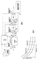
- exhaust gas temperature as a function of distance down the exhaust line 38 is shown for three operating conditions: high output (A), medium output (B), and low output (C).
- the temperatures for said first and second exhaust aftertreatment devices (20 and 26), configured as in Figure 1, are shown between dotted lines in Figure 2.
- said second exhaust aftertreatment device 26 experiences lower exhaust gas temperatures than said first exhaust aftertreatment device 20.
- Figure 3 shows exhaust aftertreatment device conversion efficiency as temperature is varied. Outside a temperature range of T min and T max , exhaust aftertreatment device conversion efficiency is too low to be viable in practice.
- Figure 4 shows that exhaust aftertreatment device conversion efficiency is sensitive to the constituents in the exhaust stream.
- a suitable reductant i.e., exhaust stream additive
- NO x feedgas concentration must be available in said exhaust aftertreatment device.
- practical viability of said exhaust aftertreatment device depends on maintaining the appropriate proportion of constituents to allow reasonable conversion efficiency.
- Figure 5 shows the combined system efficiency for the present invention in which two exhaust aftertreatment devices are placed in the exhaust system.
- the conversion efficiencies of said first and second exhaust aftertreatment devices are shown as a function of the inlet temperature to said first exhaust aftertreatment device.
- the overall efficiency for combining said exhaust aftertreatment devices is shown as the dotted line in Figure 5.
- High conversion efficiency is maintained over a wider temperature range than either exhaust aftertreatment device singly.
- Temperature A in Figure 5, corresponding to engine condition A of Figure 2 results in a situation where no appreciable conversion occurs in the first exhaust aftertreatment device. In such a case, exhaust stream additive would not be supplied to said first exhaust aftertreatment device.
- Temperature B is a condition at which neither said first or second exhaust aftertreatment devices is at high efficiency.
- the two exhaust aftertreatment devices in series results in high combined efficiency. For this case, exhaust stream additive would be supplied to both exhaust aftertreatment devices.
- FIG. 6 shows a flowchart which would be executed in the ECU 40 to command the appropriate supply of exhaust stream additive to exhaust aftertreatment devices (EADs).
- step 98 sets up a loop to execute the following steps n times, where n is the number of aftertreatment devices in said system.
- Temperatures in the exhaust aftertreatment devices are determined in step 100.
- the temperature is compared to T min and T max in step 102. If exhaust aftertreatment device temperature is outside T min and T max window, no exhaust stream additive is supplied, step 104. If said exhaust aftertreatment device temperature is within T min and T max window, the desired ratio of exhaust stream additive to NO x for said exhaust aftertreatment device is computed in step 106.
- step 108 the amount of exhaust stream additive to supply to said exhaust aftertreatment device is computed in step 108.
- Said calculation takes into account the feedgas constituent, e.g., hydrocarbon acting as a reductant presence of hydrocarbons lessens the quantity of exhaust stream additive which must be supplied.
- Said calculation further takes into account the adsorption and desorption of exhaust stream additive and hydrocarbon species from exhaust aftertreatment device surfaces.
- T min and T max of Figures 3 and 6 are not fixed quantities. They may be varied based on engine operating conditions, desired overall system response, are degradation characteristics of said exhaust aftertreatment system, among others.
- Figure 7 illustrates the steps required to determine the amount of exhaust stream additive to supply to each of said exhaust aftertreatment devices.
- step 60 the amount of hydrocarbon and NO x exhausted from the engine is determined. Either exhaust sensor 30 signals, an engine model in the ECU 40, or a combination of the two methods are used to determine said hydrocarbon and NO x concentrations in feedgas from said engine.
- the desired exhaust stream additive (ESA) to NO x ratio for said first exhaust aftertreatment device is computed in step 62.
- the amount of ESA stored and released is computed based on engine operating conditions and known adsorption/desorption characteristics of said exhaust aftertreatment device and chemical species in said ESA.
- Adsorption of said first exhaust aftertreatment device is limited by its capacity; said limit is enforced in step 66.
- step 68 the results of steps 60, 62, and 66, sources and sinks of ESA, are used to compute the amount of ESA to supply to said first exhaust aftertreatment device.
- step 70 the amount of ESA added is limited to reflect known allowable maximum based on said exhaust aftertreatment capacity, degradation, and malfunction characteristics. Said limited ESA quantity is commanded to ESA supply injector in step 72. If ESA is fuel, in-cylinder injector or injectors 15 may be used to supply ESA to post-combustion gases. If ESA is not fuel, injector 18 supplies ESA.
- step 80 The procedure for supplying ESA to said second exhaust aftertreatment device begins with steps 78 and 80, in which the NO x , hydrocarbon, and ESA as feedgas to said second exhaust aftertreatment device are computed. Steps 82 through 92 applied to said second exhaust aftertreatment device are identical to steps 62 through 72 described above for said first exhaust aftertreatment device. To one skilled in the art, it should be obvious that if no ESA is exhausted from said first aftertreatment device, step 80 requires computation of hydrocarbon quantity only.
Abstract
Description
- The invention relates to a system and method for controlling injection of exhaust stream additive into the exhaust stream of an internal combustion engine to ensure high overall NOx conversion efficiency of an exhaust aftertreatment system.
- Current automotive emission regulations necessitate the use of exhaust aftertreatment devices. Oxides of nitrogen (NOx), for example, can be reduced to nitrogen and water in a selective catalyst reduction device using externally added reducing agents. NOx conversion in a three-way catalyst operating at stoichiometric air-fuel ratio is commonly greater than 95%. Such high conversion NOx efficiencies have not been demonstrated in practice in engines in which the exhaust stream is leaner than stoichiometric. Diesel engines and lean gasoline engines operate lean and cannot, therefore, realise the high NOx conversion efficiencies of three-way catalysts.
- Exhaust aftertreatment devices for use in lean operating engine systems tend to have a narrow temperature range in which NOx is converted efficiently, compared to a three-way catalyst. Furthermore, lean exhaust aftertreatment devices require that a quantity of reducing material, e.g., fuel or ammonia, be present in proportion to the amount of NOx to be reduced. In U.S. Patent 5,628,186 a method is disclosed in which a reductant is supplied to the exhaust stream of an engine based on output from a sensor in the exhaust line. Optionally, an NOx sensor can be located in the exhaust line to refine the method. U.S. Patent 5,628,186 does not overcome the narrow temperature range difficulty with lean exhaust aftertreatment devices. In the present invention, two exhaust aftertreatment devices are employed: one in the exhaust line closer to the engine and at least one more downstream in the exhaust line. Because the temperature in the exhaust line decreases along its length, the temperatures in the exhaust aftertreatment devices are dissimilar providing an opportunity for selectively using only a device operating in the appropriate temperature range for acceptable NOx conversion.
- U.S. Patent 5,845,487 discloses a method in which two modes of operation are employed depending on the operating condition of the engine. In a first mode, injection timing is retarded which results in low feedgas NOx concentration and a penalty in fuel economy. In the second mode, injection timing is advanced which results in a fuel economy improvement at the cost of higher feedgas NOx. Exhaust stream additive is injected in the latter mode to effect reduction of NOx in an exhaust aftertreatment device. Retarding injection timing hurts fuel economy. An advantage of the present invention is that it increases the effective window of exhaust gas temperature over which acceptable NOx conversion efficiency occurs thereby eliminating or limiting the need for fuel inefficient measures as retarding injection timing.
- Other strategies have been devised in which engine operating condition is altered in pursuit of exhaust gas temperatures suitable for high NOx conversion efficiency. It is obvious to one skilled in the art that such measures lead to degradation in fuel economy, driveability, emission control of other pollutants, or a combination thereof. Even if these disadvantages could be overcome, the engine control unit must manage the engine such that a switch between desired operating condition and an engine control point for NOx reduction is imperceptible to the vehicle operator. The method and apparatus of the present invention overcome these disadvantages by improving the effective temperature window of acceptable NOx conversion efficiency.
- U.S. Patent 5,365,734 discloses a system which employs a plurality of lean NOx catalysts and exhaust conduits. The system includes valve(s) to divert the exhaust flow, with the desired outcome of controlling the space velocity in each of the catalysts to provide high conversion efficiency. A system according to the present invention, in contrast, improves upon U.S. 5,365,734 in that diverting valves and multiple exhaust ducts are not required for handling the exhaust stream. It is known in the art that exhaust ducts are harsh environments in which to place moving parts, such as a valve, which must provide robust and long-lived service. Furthermore, the present invention bases the control of active exhaust aftertreatment devices on temperature, instead of space velocity, as is the case of in U.S. 5,365,734.
- U.S. Patent 5,369,956 discloses a system employing an ammonia sensor downstream of the exhaust aftertreatment device in which the supply of exhaust stream additive is controlled so as to avoid breakthrough, i.e., exhausting unreacted ammonia. The present invention provides three advantages: an exhaust stream additive sensor is not required; exhaust stream additive is supplied to provide high NOx conversion efficiency, as opposed to merely preventing breakthrough; and, supply of exhaust stream additive is altered based on operating temperature, again to provide best NOx conversion efficiency.
- A method is disclosed in U.S. Patent 5,233,934 in which two catalysts are employed in the flue gases from a burner using NOx and ammonia sensors. Ammonia slip and NOx emissions are regulated by using nitrous oxide sensors to detect a nitrous oxide concentration. Then, the amount of nitrous oxide is optimised while maintaining ammonia slip below a threshold value. The optimisation is achieved by varying reductant injection until the minimum value of nitrous oxide as measured by the sensor is obtained. The amount of reductant injected to locate and achieve this minimum is limited by a measurement of ammonia slip from an ammonia sensor. U.S. 5,233,934 requires feedback control optimisation on sensor signals in the exhaust line which provide a delayed signal due to the transit time in the exhaust line. In the case of a burner, operating conditions are constant for long periods of time and may be changed slowly mitigating this disadvantage. However, internal combustion engines, particularly those used in transportation, must react quickly to operator demands. The present invention does not use an optimisation procedure and uses an engine model instead. Also, the present invention does not depend on exhaust gas sensors; but, if present, they can be used to refine the engine model.
- The present invention provides an exhaust aftertreatment system which includes a plurality of exhaust aftertreatement devices and the control algorithm to optimise the system for overall NOx conversion efficiency of the system. Because temperature in the exhaust line is a function of the operating condition of the engine, judicious placement of the exhaust aftertreatment devices ensures that the temperature of at least one of the exhaust aftertreatment devices is within the range which provides acceptable NOx conversion efficiency. An advantage of the present invention is that by placing exhaust aftertreatment devices at several locations along the exhaust line, exhaust aftertreatment system efficiency is optimised lessening the need for invasive, efficiency reducing measures to control exhaust gas temperature.
- Conversion of NOx to N2 and O2 requires that an appropriate ratio of reductant to NOx, as a function of temperature and space velocity, be maintained. An exhaust stream additive supply and a metering system are required. The exhaust stream additive may be hydrocarbons, urea, or other suitable reductant. The engine control unit schedules addition of exhaust stream additive to supply each of the exhaust aftertreatment devices. Input data to said engine controller used to compute exhaust stream additive quantity may include engine operating conditions (e.g., temperatures, rpm, air flowrate), exhaust aftertreatment device temperatures, and NOx, hydrocarbon, and exhaust stream additive concentrations at the inlet to each exhaust aftertreatment device. Temperature and concentration information may be modelled based on engine operating conditions or measured by sensors. Temperature and concentration information can be used to update said engine control unit's exhaust aftertreatment system model.
- A method for controlling the delivery of exhaust stream additive includes calculating which exhaust aftertreatment devices are in a temperature operating range of acceptable conversion efficiency and, thus, should be scheduled to receive exhaust stream additive. The amount of exhaust stream additive to be supplied to each scheduled aftertreatment device is computed based on the desired ratio of exhaust stream additive to NOx. Hydrocarbons or other reducing feedgas constituents lessen the need for exhaust stream additive. Thus, exhaust stream additive to be supplied is decreased in proportion to said reducing feedgas constituents. Finally, said exhaust stream additive supply devices are commanded to deliver said computed quantity. A maximum allowable amount of exhaust stream additive can be used to limit exhaust stream additive.
- Other factors which may be handled in said engine control unit's algorithm for computing exhaust stream additive delivery are exhaust stream additive absorption maximum of each exhaust aftertreatment device and maximum allowable exhaust stream additive to supply due to exhaust aftertreatment device degradation. Said exhaust aftertreatment device degradation may be based on the integral of exhaust gas temperature with respect to time entering said exhaust aftertreatment. Exhaust aftertreatment device storage, desired exhaust stream additive ratio, and NOx conversion rates are modified based on said exhaust aftertreatment device degradation.
- Any of exhaust temperature, exhaust stream additive, or NOx sensors may be placed in the exhaust line to provide information which may be used by the engine control unit's internal exhaust system model. Such data could be used to adapt the system model. Herein, adapt means altering exhaust system model constants to reduce the error between model estimations and data acquired from sensors.
- An exhaust aftertreatment system for an internal combustion engine includes a first fluid supply device for supplying an exhaust stream additive into exhaust gases flowing from the internal combustion engine through an exhaust line and a first exhaust aftertreatment device located in the exhaust line downstream of said first exhaust stream additive supply device. The system also comprises at least one additional exhaust aftertreatment device located in the exhaust line downstream of the first exhaust aftertreatment device and at least one additional fluid supply device for supplying an exhaust stream additive to said exhaust gases upstream of said additional exhaust aftertreatment device(s). The system further includes at least one sensor for providing signals from which engine air flow can be computed by an engine control unit and an engine control unit for scheduling the supply of exhaust stream additive to said first and additional exhaust aftertreatment devices at a rate determined from a plurality of engine and exhaust system operating characteristics.
- A method to be disposed in an engine control unit for metering exhaust stream additive to more than one exhaust aftertreatment device in an exhaust aftertreatment system includes the steps of determining the temperature of a first exhaust aftertreatment device and any other exhaust aftertreatment devices and determining which exhaust aftertreatment devices are at temperatures at which conversion efficiency is sufficient alone or as a system with other exhaust aftertreatment devices and should thus be scheduled to receive exhaust stream additive. The method further includes steps for computing desired exhaust stream additive ratio, that is, the ratio between exhaust stream additive to NOx, for each exhaust aftertreatment device scheduled to receive exhaust stream additive and using said desired exhaust stream additive ratio and feedgas composition to compute exhaust stream additive quantity to supply to each exhaust aftertreatment device. The method further includes the steps of determining the quantity of hydrocarbon and other reducing species in the exhaust gas stream, decreasing exhaust stream additive quantity to each scheduled exhaust aftertreatment device to account for the reducing action of reducing species at inlet to each scheduled exhaust stream device, and using exhaust stream additive quantity to supply to each exhaust aftertreatment device to command supply by the exhaust stream additive injectors.
- A method for controlling delivery of exhaust stream additive to an exhaust aftertreatment system with more than one exhaust aftertreatment device coupled to an automotive engine, includes the steps of computing the quantity of NOx and reducing species constituents of engine feedgas, computing desired exhaust stream additive ratio, that is, the ratio between exhaust stream additive to NOx, for a first exhaust aftertreatment device to achieve high exhaust system conversion efficiency in the first exhaust aftertreatment device, computing exhaust stream additive quantity which must be injected from an exhaust stream additive supply into the exhaust stream entering the first exhaust aftertreatment device such that desired exhaust stream additive ratio is attained, and decreasing the quantity of exhaust stream additive to account for the reducing ability of feedgas constituents. The method further includes the steps of computing the amount of NOx exiting said first exhaust aftertreatment device based on NOx entering the first exhaust aftertreatment device less the amount converted in the first exhaust aftertreatment device, computing the quantity of reducing species exhausted from the first exhaust aftertreatment device, computing the desired exhaust stream additive ratio for a second exhaust aftertreatment device to achieve high exhaust system conversion efficiency, computing the quantity of exhaust stream additive which must be injected from the exhaust stream additive supply into the exhaust stream entering the second exhaust aftertreatment device such that the desired exhaust stream additive ratio is attained, decreasing the quantity of exhaust stream additive to supply to the second exhaust aftertreatment device to account for the reducing ability of feedgas constituents to the second exhaust aftertreatment device, and commanding exhaust stream additive injectors to supply exhaust stream additive.
- The present invention will now be described further, by way of example, with reference to the accompanying drawings, in which:
- Figure 1 is a block diagram of an embodiment wherein the invention is used to advantage;
- Figure 2 is a graph which indicates the temperature profile in the exhaust system at a range of engine operating conditions;
- Figures 3-5 are graphs showing the exhaust aftertreatment conversion efficiency as temperature is varied, as composition of the exhaust gases are varied, and for the combination of two exhaust aftertreatment devices; and
- Figures 6-7 are high level flow charts of various operations performed by the embodiment shown in Figure 1.
-
-
Internal combustion engine 10, as shown in Figure 1, is controlled by electronic engine control unit (ECU) 40.Engine 10 includes intake system 14 into whichsensor 12 is placed. Sensor(s) 12 provides a signal(s) to ECU 40 from which air mass flow rate can be computed. Fuel forengine 10 is supplied and metered by fuel injectors 15. Said fuel injectors 15 could be in-cylinder or port injectors. Exhaust products are removed fromengine 10 viaexhaust line 38. Temperature sensor 16 inexhaust line 38 placed downstream ofengine 10 provides a signal to the ECU 40 of the exhaust gas temperature. Exhaust gas sensors 30 provide signals of HC and NOx concentrations to the ECU 40. Afirst injector 18 supplies reductant to exhaustaftertreatment device 20 and is located upstream of saidexhaust aftertreatment device 20 and downstream of the exhaust gas sensors 30. Saidfirst injector 18 is supplied by an exhaust streamadditive supply 28. Asecond temperature sensor 24 andexhaust gas sensors 32 are located downstream ofexhaust aftertreatment device 20. A second injector 22 supplies reductant to exhaust aftertreatment device 26 and is located upstream of said exhaust aftertreatment device 26.Exhaust gas sensors 34 are located downstream of said exhaust aftertreatment device 26. - Temperature sensors (16 and 24) and exhaust gas sensors (30, 32, and 34) are optional because an engine and exhaust system model in the ECU 40 or a lookup table in the ECU 40 could be used to estimate temperatures and exhaust gas constituent concentrations based on engine operating conditions. Alternatively, temperature sensors (16 and 24) and exhaust gas sensors (30, 32, and 34) can be used in combination with ECU models or lookup tables to improve the accuracy of the control scheme or can be used to refine ECU models or lookup tables as the exhaust aftertreatment system ages.
- One skilled in the art will appreciate that said exhaust stream additive may be fuel or materials such as urea or hydrocarbons other than the type used in the main supply to the engine. If the exhaust stream additive is fuel and fuel injectors 15 are mounted in-cylinder, said
first injector 18 may be supplanted by fuel injectors 15 which can supply fuel to the post combustion gases for use inexhaust aftertreatment device 20. - In Figure 2, exhaust gas temperature as a function of distance down the
exhaust line 38 is shown for three operating conditions: high output (A), medium output (B), and low output (C). The temperatures for said first and second exhaust aftertreatment devices (20 and 26), configured as in Figure 1, are shown between dotted lines in Figure 2. Clearly, said second exhaust aftertreatment device 26 experiences lower exhaust gas temperatures than said firstexhaust aftertreatment device 20. - Figure 3 shows exhaust aftertreatment device conversion efficiency as temperature is varied. Outside a temperature range of Tmin and Tmax, exhaust aftertreatment device conversion efficiency is too low to be viable in practice.
- Figure 4 shows that exhaust aftertreatment device conversion efficiency is sensitive to the constituents in the exhaust stream. For NOx conversion, a suitable reductant, i.e., exhaust stream additive, in a proportion appropriate for the operating conditions and NOx feedgas concentration must be available in said exhaust aftertreatment device. As with temperature, practical viability of said exhaust aftertreatment device depends on maintaining the appropriate proportion of constituents to allow reasonable conversion efficiency.
- Figure 5 shows the combined system efficiency for the present invention in which two exhaust aftertreatment devices are placed in the exhaust system. The conversion efficiencies of said first and second exhaust aftertreatment devices are shown as a function of the inlet temperature to said first exhaust aftertreatment device. The overall efficiency for combining said exhaust aftertreatment devices is shown as the dotted line in Figure 5. High conversion efficiency is maintained over a wider temperature range than either exhaust aftertreatment device singly. Temperature A in Figure 5, corresponding to engine condition A of Figure 2, results in a situation where no appreciable conversion occurs in the first exhaust aftertreatment device. In such a case, exhaust stream additive would not be supplied to said first exhaust aftertreatment device. The opposite is true for temperature C in Figure 5 in which exhaust stream additive would not be supplied to the second exhaust aftertreatment device. Temperature B is a condition at which neither said first or second exhaust aftertreatment devices is at high efficiency. However, the two exhaust aftertreatment devices in series results in high combined efficiency. For this case, exhaust stream additive would be supplied to both exhaust aftertreatment devices.
- Figure 6 shows a flowchart which would be executed in the ECU 40 to command the appropriate supply of exhaust stream additive to exhaust aftertreatment devices (EADs). As the flowchart of Figure 6 is carried out for each exhaust aftertreatment device, step 98 sets up a loop to execute the following steps n times, where n is the number of aftertreatment devices in said system. Temperatures in the exhaust aftertreatment devices are determined in
step 100. Next, the temperature is compared to Tmin and Tmax instep 102. If exhaust aftertreatment device temperature is outside Tmin and Tmax window, no exhaust stream additive is supplied,step 104. If said exhaust aftertreatment device temperature is within Tmin and Tmax window, the desired ratio of exhaust stream additive to NOx for said exhaust aftertreatment device is computed instep 106. Next, the amount of exhaust stream additive to supply to said exhaust aftertreatment device is computed instep 108. Said calculation takes into account the feedgas constituent, e.g., hydrocarbon acting as a reductant presence of hydrocarbons lessens the quantity of exhaust stream additive which must be supplied. Said calculation further takes into account the adsorption and desorption of exhaust stream additive and hydrocarbon species from exhaust aftertreatment device surfaces. - It can be appreciated by one skilled in the art that Tmin and Tmax of Figures 3 and 6 are not fixed quantities. They may be varied based on engine operating conditions, desired overall system response, are degradation characteristics of said exhaust aftertreatment system, among others.
- Figure 7 illustrates the steps required to determine the amount of exhaust stream additive to supply to each of said exhaust aftertreatment devices. In
step 60, the amount of hydrocarbon and NOx exhausted from the engine is determined. Either exhaust sensor 30 signals, an engine model in the ECU 40, or a combination of the two methods are used to determine said hydrocarbon and NOx concentrations in feedgas from said engine. Independently, the desired exhaust stream additive (ESA) to NOx ratio for said first exhaust aftertreatment device is computed instep 62. In a furtherindependent step 64, the amount of ESA stored and released is computed based on engine operating conditions and known adsorption/desorption characteristics of said exhaust aftertreatment device and chemical species in said ESA. Adsorption of said first exhaust aftertreatment device is limited by its capacity; said limit is enforced instep 66. Instep 68, the results ofsteps step 70, the amount of ESA added is limited to reflect known allowable maximum based on said exhaust aftertreatment capacity, degradation, and malfunction characteristics. Said limited ESA quantity is commanded to ESA supply injector instep 72. If ESA is fuel, in-cylinder injector or injectors 15 may be used to supply ESA to post-combustion gases. If ESA is not fuel,injector 18 supplies ESA. - The procedure for supplying ESA to said second exhaust aftertreatment device begins with
steps Steps 82 through 92 applied to said second exhaust aftertreatment device are identical tosteps 62 through 72 described above for said first exhaust aftertreatment device. To one skilled in the art, it should be obvious that if no ESA is exhausted from said first aftertreatment device,step 80 requires computation of hydrocarbon quantity only.
Claims (13)
- An exhaust aftertreatment system for an internal combustion engine comprising:a first fluid supply device (18,28) for supplying an exhaust stream additive into the exhaust gases flowing from said internal combustion engine (10) and through an exhaust line (38) ;a first exhaust aftertreatment device (20) located in the exhaust line (38) downstream of said first exhaust stream additive supply device;at least one additional exhaust aftertreatment device (26) located in said exhaust line (38) downstream of said first exhaust aftertreatment device (20);at least one additional fluid supply device (22,28) for supplying an exhaust stream additive to said exhaust gases upstream of said additional exhaust aftertreatment device(s) (26) ;an engine control unit (40) andat least one sensor (30,32,34) for providing signals from which engine air flow can be computed by the engine control unit (40) ;the engine control unit (40) being capable of scheduling the supply of exhaust stream additive to said first and additional exhaust aftertreatment devices at a rate determined from a plurality of engine and exhaust system operating characteristics.
- A system according to claim 1, wherein said first fluid supply device comprises an injector located in said exhaust line.
- A system according to claim 1, wherein said exhaust stream comprises fuel which is supplied and metered by one or more in-cylinder fuel injectors scheduled to inject during the latter portion of an expansion stroke and into an exhaust stroke.
- A system according to claim 1, further comprising a plurality of temperature sensors located within said aftertreatment system so as to measure the inlet gas temperature to each of said exhaust aftertreatment devices.
- A system according to claim 1, further comprising a plurality of exhaust stream additive sensors located in said exhaust line both upstream and downstream of said first exhaust aftertreatment device and in said exhaust line downstream from said second exhaust aftertreatment device.
- A system according to claim 1, wherein NOx sensors are located upstream and downstream of said first exhaust aftertreatment device and downstream of said additional exhaust aftertreatment device.
- A method to be disposed in an engine control unit for metering exhaust stream additive to more than one exhaust aftertreatment device in an exhaust aftertreatment system comprising the steps of:determining the temperature of a first exhaust aftertreatment device and any other exhaust aftertreatment devices;determining which exhaust aftertreatment devices are at temperatures at which conversion efficiency is sufficient alone or as a system with other exhaust aftertreatment devices and should thus be scheduled to receive exhaust stream additive;computing desired exhaust stream additive ratio, that is, the ratio between exhaust stream additive to NOx, for each exhaust aftertreatment device scheduled to receive exhaust stream additive;using said desired exhaust stream additive ratio and feedgas composition to compute exhaust stream additive quantity to supply to each exhaust aftertreatment device;determining the quantity of hydrocarbon and other reducing species in the exhaust gas stream;decreasing exhaust stream additive quantity to each scheduled exhaust aftertreatment device to account for reducing action of reducing species at inlet to each scheduled exhaust stream device; andusing said exhaust stream additive quantity to supply to each exhaust aftertreatment device to command supply by the exhaust stream additive injectors.
- A method according to claim 7, further comprising the step of limiting said amount of exhaust stream additive quantity to be injected by a known maximum allowable amount.
- A method according to claim 7, further comprising the step of limiting said exhaust stream additive quantity to account for the maximum exhaust stream additive storage capacity in said exhaust aftertreatment system.
- A method according to claim 7, further comprising the step of using signals from temperature sensors located in said exhaust line are used to adapt said engine control unit's exhaust aftertreatment system model.
- A method according to claim 7, further comprising the step in which signals from exhaust stream additive sensors located in said exhaust line are used to adapt said engine control unit's exhaust aftertreatment system model.
- A method according to claim 7, further comprising the step in which signals from NOx sensors located in said exhaust line are used to adapt said engine control unit's exhaust aftertreatment system model.
- A method according to claim 7, further comprising a step in which exhaust aftertreatment device degradation is computed based on the integral with respect to time of temperature of gases entering the exhaust aftertreatment device. Exhaust aftertreatment device storage, said desired exhaust stream additive ratio, and conversion rates are functions of said exhaust aftertreatment device degradation.
Applications Claiming Priority (2)
| Application Number | Priority Date | Filing Date | Title |
|---|---|---|---|
| US521395 | 2000-03-08 | ||
| US09/521,395 US6269633B1 (en) | 2000-03-08 | 2000-03-08 | Emission control system |
Publications (2)
| Publication Number | Publication Date |
|---|---|
| EP1132585A2 true EP1132585A2 (en) | 2001-09-12 |
| EP1132585A3 EP1132585A3 (en) | 2003-05-07 |
Family
ID=24076574
Family Applications (1)
| Application Number | Title | Priority Date | Filing Date |
|---|---|---|---|
| EP01301005A Withdrawn EP1132585A3 (en) | 2000-03-08 | 2001-02-05 | Emission control system |
Country Status (2)
| Country | Link |
|---|---|
| US (1) | US6269633B1 (en) |
| EP (1) | EP1132585A3 (en) |
Cited By (5)
| Publication number | Priority date | Publication date | Assignee | Title |
|---|---|---|---|---|
| WO2006097268A1 (en) | 2005-03-18 | 2006-09-21 | Daimlerchrysler Ag | Device for removing nitrogen oxides from internal combustion engine waste gas and method for dosing an aggregate of internal combustion engine waste gas |
| WO2007001500A1 (en) | 2005-06-21 | 2007-01-04 | Exxonmobil Research And Engineering Company | Method and apparatus for reducing nox with first and second catalysis |
| US7743602B2 (en) | 2005-06-21 | 2010-06-29 | Exxonmobil Research And Engineering Co. | Reformer assisted lean NOx catalyst aftertreatment system and method |
| US7833495B2 (en) | 2005-05-06 | 2010-11-16 | Ford Global Technologies, Llc | Exhaust treatment device facilitating through-wall flow |
| EP3364007A1 (en) * | 2017-02-16 | 2018-08-22 | Toyota Jidosha Kabushiki Kaisha | Exhaust gas purification apparatus for an internal combustion engine |
Families Citing this family (74)
| Publication number | Priority date | Publication date | Assignee | Title |
|---|---|---|---|---|
| DE60140104D1 (en) * | 2000-06-13 | 2009-11-19 | Ford Global Tech Inc | A method for optimizing the addition of a reducing agent to an SCR catalytic converter of an internal combustion engine |
| US6758036B1 (en) * | 2000-10-27 | 2004-07-06 | Delphi Technologies, Inc. | Method for sulfur protection of NOx adsorber |
| DE10126456B4 (en) * | 2001-05-31 | 2004-05-19 | Daimlerchrysler Ag | Apparatus and method for removing nitrogen oxides from the exhaust lean burned internal combustion engines |
| US20040007056A1 (en) * | 2001-08-06 | 2004-01-15 | Webb Cynthia C. | Method for testing catalytic converter durability |
| US6983645B2 (en) * | 2002-08-06 | 2006-01-10 | Southwest Research Institute | Method for accelerated aging of catalytic converters incorporating engine cold start simulation |
| US7741127B2 (en) * | 2001-08-06 | 2010-06-22 | Southwest Research Institute | Method for producing diesel exhaust with particulate material for testing diesel engine aftertreatment devices |
| US7175422B2 (en) * | 2001-08-06 | 2007-02-13 | Southwest Research Institute | Method for accelerated aging of catalytic converters incorporating injection of volatilized lubricant |
| US20050042763A1 (en) * | 2002-08-06 | 2005-02-24 | Southwest Research Institute | Testing using diesel exhaust produced by a non-engine based test system |
| EP1415111A4 (en) * | 2001-08-06 | 2006-07-05 | Southwest Res Inst | Method and apparatus for testing catalytic converter durability |
| US7412335B2 (en) * | 2002-08-06 | 2008-08-12 | Southwest Research Institute | Component evaluations using non-engine based test system |
| US7212926B2 (en) * | 2002-08-06 | 2007-05-01 | Southwest Research Institute | Testing using a non-engine based test system and exhaust product comprising alternative fuel exhaust |
| US7299137B2 (en) * | 2002-08-06 | 2007-11-20 | Southwest Research Institute | Method for drive cycle simulation using non-engine based test system |
| US6993900B2 (en) | 2002-10-21 | 2006-02-07 | Ford Global Technologies, Llc | Exhaust gas aftertreatment systems |
| US6832473B2 (en) | 2002-11-21 | 2004-12-21 | Delphi Technologies, Inc. | Method and system for regenerating NOx adsorbers and/or particulate filters |
| US6834498B2 (en) | 2002-11-21 | 2004-12-28 | Ford Global Technologies, Llc | Diesel aftertreatment systems |
| US6895747B2 (en) | 2002-11-21 | 2005-05-24 | Ford Global Technologies, Llc | Diesel aftertreatment systems |
| US7093427B2 (en) | 2002-11-21 | 2006-08-22 | Ford Global Technologies, Llc | Exhaust gas aftertreatment systems |
| US6823663B2 (en) | 2002-11-21 | 2004-11-30 | Ford Global Technologies, Llc | Exhaust gas aftertreatment systems |
| US6862879B2 (en) | 2002-11-21 | 2005-03-08 | Ford Global Technologies, Llc | Diesel aftertreatment system |
| US6892530B2 (en) | 2002-11-21 | 2005-05-17 | Ford Global Technologies, Llc | Exhaust gas aftertreatment systems |
| US6928806B2 (en) * | 2002-11-21 | 2005-08-16 | Ford Global Technologies, Llc | Exhaust gas aftertreatment systems |
| US6981368B2 (en) * | 2002-11-21 | 2006-01-03 | Ford Global Technologies, Llc | Exhaust gas aftertreatment systems |
| US6761025B1 (en) * | 2002-12-19 | 2004-07-13 | Caterpillar Inc. | Enhanced ammonia feed control for selective catalytic reduction |
| US20050022450A1 (en) * | 2003-02-12 | 2005-02-03 | Cher-Dip Tan | Reformer system, a method of producing hydrogen in the reformer system, and a method of using the reformer system |
| US6922987B2 (en) | 2003-02-12 | 2005-08-02 | Fleetguard, Inc. | System and method for enhancing internal combustion engine aftertreatment applications by superheated fuel injection |
| US7767163B2 (en) * | 2004-04-20 | 2010-08-03 | Umicore Ag & Co. Kg | Exhaust treatment devices |
| US6996975B2 (en) * | 2004-06-25 | 2006-02-14 | Eaton Corporation | Multistage reductant injection strategy for slipless, high efficiency selective catalytic reduction |
| US20070193254A1 (en) * | 2004-07-29 | 2007-08-23 | Johannes Erik P | Combustion engine exhaust after-treatment system incorporating syngas generator |
| DE102004046640B4 (en) * | 2004-09-25 | 2013-07-11 | Robert Bosch Gmbh | Method for operating an internal combustion engine and device for carrying out the method |
| US20060112678A1 (en) * | 2004-11-04 | 2006-06-01 | Eaton Corporation | Multiple reactant multiple catalyst selective catalytic reduction for NOx abatement in internal combustion engines |
| US7435275B2 (en) * | 2005-08-11 | 2008-10-14 | Delphi Technologies, Inc. | System and method of heating an exhaust treatment device |
| US7155334B1 (en) * | 2005-09-29 | 2006-12-26 | Honeywell International Inc. | Use of sensors in a state observer for a diesel engine |
| US20070084116A1 (en) * | 2005-10-13 | 2007-04-19 | Bayerische Motoren Werke Aktiengesellschaft | Reformer system having electrical heating devices |
| US7485272B2 (en) * | 2005-11-30 | 2009-02-03 | Caterpillar Inc. | Multi-stage system for selective catalytic reduction |
| JP5087836B2 (en) * | 2005-12-14 | 2012-12-05 | いすゞ自動車株式会社 | Exhaust gas purification system control method and exhaust gas purification system |
| SE529410C2 (en) * | 2005-12-20 | 2007-08-07 | Scania Cv Abp | Method and apparatus for monitoring the function of a sensor or system |
| US7805929B2 (en) * | 2005-12-21 | 2010-10-05 | Caterpillar Inc | Selective catalytic reduction system |
| JP4432917B2 (en) * | 2006-03-06 | 2010-03-17 | トヨタ自動車株式会社 | Exhaust gas purification device for internal combustion engine |
| US7469531B2 (en) * | 2006-09-20 | 2008-12-30 | Gm Global Technology Operations, Inc. | Method and apparatus to control injection of a reductant into an exhaust gas feedstream |
| US7717205B2 (en) * | 2006-11-28 | 2010-05-18 | Caterpillar Inc. | Engine hood assembly enclosure with exhaust aftertreatment device integrated therein, and machine using same |
| JP4459987B2 (en) * | 2007-06-27 | 2010-04-28 | 株式会社デンソー | Exhaust purification agent addition amount control device and exhaust purification system |
| JP4388103B2 (en) * | 2007-06-27 | 2009-12-24 | 株式会社デンソー | Exhaust purification agent addition amount control device and exhaust purification system |
| US9234474B2 (en) * | 2007-06-28 | 2016-01-12 | GM Global Technology Operations LLC | Control oriented model for LNT regeneration |
| DE102007044610B4 (en) * | 2007-09-19 | 2010-04-08 | Continental Automotive Gmbh | A method of detecting the minimum opening time of a reductant delivery device in an exhaust aftertreatment system with an SCR catalyst |
| KR100999617B1 (en) * | 2007-12-14 | 2010-12-08 | 현대자동차주식회사 | Monitoring system for selective catalytic reduction of vehicle |
| US8505278B2 (en) * | 2009-04-30 | 2013-08-13 | Cummins Ip, Inc. | Engine system properties controller |
| US8161730B2 (en) * | 2008-04-30 | 2012-04-24 | Cummins Ip, Inc. | Apparatus, system, and method for reducing NOx emissions on an SCR catalyst |
| US8201394B2 (en) * | 2008-04-30 | 2012-06-19 | Cummins Ip, Inc. | Apparatus, system, and method for NOx signal correction in feedback controls of an SCR system |
| US8256208B2 (en) * | 2008-04-30 | 2012-09-04 | Cummins Ip, Inc. | Apparatus, system, and method for reducing NOx emissions on an SCR catalyst |
| US8141340B2 (en) * | 2008-04-30 | 2012-03-27 | Cummins Ip, Inc | Apparatus, system, and method for determining the degradation of an SCR catalyst |
| US8181450B2 (en) * | 2008-04-30 | 2012-05-22 | Cummins IP. Inc. | Apparatus, system, and method for reducing NOx emissions on an SCR catalyst using ammonia storage and slip control |
| US8281572B2 (en) * | 2008-04-30 | 2012-10-09 | Cummins Ip, Inc. | Apparatus, system, and method for reducing NOx emissions from an engine system |
| JP4995800B2 (en) * | 2008-10-29 | 2012-08-08 | 日本特殊陶業株式会社 | Method and apparatus for detecting abnormality of nitrogen oxide purification catalyst |
| US8356471B2 (en) * | 2008-12-05 | 2013-01-22 | Cummins Ip, Inc. | Apparatus, system, and method for controlling reductant dosing in an SCR catalyst system |
| US8225595B2 (en) * | 2008-12-05 | 2012-07-24 | Cummins Ip, Inc. | Apparatus, system, and method for estimating an NOx conversion efficiency of a selective catalytic reduction catalyst |
| US20110252771A1 (en) * | 2008-12-08 | 2011-10-20 | Mitsubishi Heavy Industries, Ltd. | Flue gas purifying device |
| WO2010106695A1 (en) * | 2009-03-19 | 2010-09-23 | トヨタ自動車株式会社 | Exhaust purifying device for internal combustion engine |
| WO2010128563A1 (en) * | 2009-05-07 | 2010-11-11 | トヨタ自動車株式会社 | Exhaust gas purifying device for internal combustion engine |
| US9133749B2 (en) * | 2009-07-10 | 2015-09-15 | Kevin Andrew Gady | Ammonia storage set-point control for selective catalytic reduction applications |
| WO2011032020A2 (en) * | 2009-09-10 | 2011-03-17 | Cummins Ip, Inc. | Low temperature selective catalytic reduction catalyst and associated systems and methods |
| US8733083B2 (en) | 2010-04-26 | 2014-05-27 | Cummins Filtration Ip, Inc. | SCR catalyst ammonia surface coverage estimation and control |
| US8820051B2 (en) * | 2010-08-10 | 2014-09-02 | GM Global Technology Operations LLC | Vehicle oxidation catalyst efficiency model for adaptive control and diagnostics |
| US20130152545A1 (en) * | 2011-12-14 | 2013-06-20 | Caterpillar Inc. | Diesel eission fluid quality detection system and method |
| DE102012002061A1 (en) * | 2012-02-03 | 2013-08-08 | Emitec Gesellschaft Für Emissionstechnologie Mbh | Dosing valve for freeze-risk additives |
| US9273577B2 (en) | 2012-10-30 | 2016-03-01 | Cummins Inc. | Multi-leg aftertreatment system |
| EP3033308B1 (en) | 2013-08-13 | 2018-10-03 | Draka Comteq BV | Optical fiber preform and method for manufacturing such optical fiber preform from a primary preform |
| US9567888B2 (en) * | 2014-03-27 | 2017-02-14 | Cummins Inc. | Systems and methods to reduce reductant consumption in exhaust aftertreament systems |
| EP2955351B1 (en) | 2014-06-12 | 2017-07-26 | Toyota Jidosha Kabushiki Kaisha | Filling of an urea water supply system |
| JP6477250B2 (en) * | 2014-06-12 | 2019-03-06 | トヨタ自動車株式会社 | Urea water supply system |
| GB2541229A (en) * | 2015-08-13 | 2017-02-15 | Gm Global Tech Operations Llc | Method of operating an automotive system |
| US9765674B2 (en) * | 2015-09-09 | 2017-09-19 | Cummins Emission Solutions Inc. | Asynchronous reductant insertion in aftertreatment systems |
| US10247075B2 (en) * | 2016-05-10 | 2019-04-02 | Cummins Emission Solutions Inc. | Systems and methods for reducing noise in reductant insertion assemblies |
| CN108915827B (en) * | 2018-07-04 | 2020-02-11 | 中国汽车技术研究中心有限公司 | Method for improving NOx emission of engine based on SCR chemical reaction mathematical model |
| CN113924408B (en) | 2019-05-09 | 2023-11-14 | 康明斯排放处理公司 | Valve device for split-flow close-coupled catalyst |
Citations (4)
| Publication number | Priority date | Publication date | Assignee | Title |
|---|---|---|---|---|
| US5365734A (en) | 1992-03-25 | 1994-11-22 | Toyota Jidosha Kabushiki Kaisha | NOx purification apparatus for an internal combustion engine |
| US5369956A (en) | 1992-05-27 | 1994-12-06 | Mercedes-Benz Ag | Exhaust gas aftertreatment device for internal combustion engines |
| US5628186A (en) | 1993-05-07 | 1997-05-13 | Siemens Aktiengesellschaft | Method and apparatus for controlled introduction of a reducing agent into a nitrogen oxide-containing exhaust gas |
| US5845487A (en) | 1996-07-19 | 1998-12-08 | Daimler-Benz Ag | Method and device for operating an internal combustion engine with low nitrogen oxide emissions |
Family Cites Families (16)
| Publication number | Priority date | Publication date | Assignee | Title |
|---|---|---|---|---|
| US5201802A (en) * | 1991-02-04 | 1993-04-13 | Toyota Jidosha Kabushiki Kaisha | Exhaust gas purification system for an internal combustion engine |
| US5272871A (en) * | 1991-05-24 | 1993-12-28 | Kabushiki Kaisha Toyota Chuo Kenkyusho | Method and apparatus for reducing nitrogen oxides from internal combustion engine |
| JPH05106430A (en) * | 1991-10-16 | 1993-04-27 | Toyota Central Res & Dev Lab Inc | Nitrogen oxide reducing device for internal combustion engine |
| US5233934A (en) | 1992-08-20 | 1993-08-10 | Wahlco Environmental Systems, Inc. | Control of NOx reduction in flue gas flows |
| DE4338883B4 (en) * | 1992-11-24 | 2005-03-03 | Volkswagen Ag | Catalyst arrangement for reducing nitrogen oxides contained in oxygen-containing exhaust gases |
| US5426934A (en) * | 1993-02-10 | 1995-06-27 | Hitachi America, Ltd. | Engine and emission monitoring and control system utilizing gas sensors |
| EP0621400B1 (en) * | 1993-04-23 | 1999-03-31 | Daimler-Benz Aktiengesellschaft | Air compressing injection internal combustion engine with an exhaust gas treating device for reducing nitrous oxides |
| WO1997012129A2 (en) * | 1995-09-29 | 1997-04-03 | Siemens Aktiengesellschaft | Process and device for reacting a pollutant in an exhaust gas on a catalyst |
| US5921076A (en) * | 1996-01-09 | 1999-07-13 | Daimler-Benz Ag | Process and apparatus for reducing nitrogen oxides in engine emissions |
| DE19644407C2 (en) * | 1996-10-25 | 1999-09-23 | Daimler Chrysler Ag | Process for reducing the emissions of an internal combustion engine |
| US5910096A (en) * | 1997-12-22 | 1999-06-08 | Ford Global Technologies, Inc. | Temperature control system for emission device coupled to direct injection engines |
| JP3951422B2 (en) * | 1998-03-23 | 2007-08-01 | トヨタ自動車株式会社 | Exhaust purification device for multi-cylinder internal combustion engine |
| JP3482874B2 (en) * | 1998-05-28 | 2004-01-06 | トヨタ自動車株式会社 | Exhaust gas purification device for internal combustion engine |
| US6122909A (en) * | 1998-09-29 | 2000-09-26 | Lynntech, Inc. | Catalytic reduction of emissions from internal combustion engines |
| US6125629A (en) * | 1998-11-13 | 2000-10-03 | Engelhard Corporation | Staged reductant injection for improved NOx reduction |
| US6182444B1 (en) * | 1999-06-07 | 2001-02-06 | Ford Global Technologies, Inc. | Emission control system |
-
2000
- 2000-03-08 US US09/521,395 patent/US6269633B1/en not_active Expired - Fee Related
-
2001
- 2001-02-05 EP EP01301005A patent/EP1132585A3/en not_active Withdrawn
Patent Citations (4)
| Publication number | Priority date | Publication date | Assignee | Title |
|---|---|---|---|---|
| US5365734A (en) | 1992-03-25 | 1994-11-22 | Toyota Jidosha Kabushiki Kaisha | NOx purification apparatus for an internal combustion engine |
| US5369956A (en) | 1992-05-27 | 1994-12-06 | Mercedes-Benz Ag | Exhaust gas aftertreatment device for internal combustion engines |
| US5628186A (en) | 1993-05-07 | 1997-05-13 | Siemens Aktiengesellschaft | Method and apparatus for controlled introduction of a reducing agent into a nitrogen oxide-containing exhaust gas |
| US5845487A (en) | 1996-07-19 | 1998-12-08 | Daimler-Benz Ag | Method and device for operating an internal combustion engine with low nitrogen oxide emissions |
Cited By (9)
| Publication number | Priority date | Publication date | Assignee | Title |
|---|---|---|---|---|
| WO2006097268A1 (en) | 2005-03-18 | 2006-09-21 | Daimlerchrysler Ag | Device for removing nitrogen oxides from internal combustion engine waste gas and method for dosing an aggregate of internal combustion engine waste gas |
| US8061122B2 (en) | 2005-03-18 | 2011-11-22 | Daimler Ag | Device for removing nitrogen oxides from internal combustion engine waste gas and method for dosing an aggregate of internal combustion engine waste gas |
| US7833495B2 (en) | 2005-05-06 | 2010-11-16 | Ford Global Technologies, Llc | Exhaust treatment device facilitating through-wall flow |
| US8133842B2 (en) | 2005-05-06 | 2012-03-13 | Ford Global Technologies, Llc | Exhaust treatment device facilitating through-wall flow |
| WO2007001500A1 (en) | 2005-06-21 | 2007-01-04 | Exxonmobil Research And Engineering Company | Method and apparatus for reducing nox with first and second catalysis |
| US7743602B2 (en) | 2005-06-21 | 2010-06-29 | Exxonmobil Research And Engineering Co. | Reformer assisted lean NOx catalyst aftertreatment system and method |
| US7803338B2 (en) | 2005-06-21 | 2010-09-28 | Exonmobil Research And Engineering Company | Method and apparatus for combination catalyst for reduction of NOx in combustion products |
| EP3364007A1 (en) * | 2017-02-16 | 2018-08-22 | Toyota Jidosha Kabushiki Kaisha | Exhaust gas purification apparatus for an internal combustion engine |
| CN108442999A (en) * | 2017-02-16 | 2018-08-24 | 丰田自动车株式会社 | The emission-control equipment of internal combustion engine |
Also Published As
| Publication number | Publication date |
|---|---|
| US6269633B1 (en) | 2001-08-07 |
| EP1132585A3 (en) | 2003-05-07 |
Similar Documents
| Publication | Publication Date | Title |
|---|---|---|
| US6269633B1 (en) | Emission control system | |
| US6427439B1 (en) | Method and system for NOx reduction | |
| US9133749B2 (en) | Ammonia storage set-point control for selective catalytic reduction applications | |
| US7134273B2 (en) | Exhaust emission control and diagnostics | |
| US6701707B1 (en) | Exhaust emission diagnostics | |
| US6901744B2 (en) | Air-fuel ratio control apparatus of internal combustion engine | |
| EP1129278B1 (en) | STAGED REDUCTANT INJECTION FOR IMPROVED NO x? REDUCTION | |
| US8965664B2 (en) | Controller for plant | |
| US8196391B2 (en) | SCR emissions-control system | |
| US20100122524A1 (en) | AMMONIA (NH3) STORAGE CONTROL SYSTEM AND METHOD AT LOW NITROGEN OXIDE (NOx) MASS FLOW RATES | |
| US20020184879A1 (en) | System & method for controlling the air / fuel ratio in an internal combustion engine | |
| US20100199634A1 (en) | Exhaust treatment system implementing selective doc bypass | |
| KR100629205B1 (en) | Exhaust gas cleaning device for engine | |
| JP2000265828A (en) | Exhaust emission control device for internal combustion engine | |
| US10859018B1 (en) | Exhaust gas purification system using three-way catalyst and method of controlling the same | |
| US8551432B2 (en) | System and method for injecting ammonia into an exhaust gas stream | |
| US9644513B2 (en) | Method of regenerating lean NOx trap of exhaust purification system provided with lean NOx trap and selective catalytic reduction catalyst and exhaust purification system | |
| JP2002038926A (en) | Exhaust emission control device of internal combustion engine | |
| US10683785B2 (en) | Exhaust gas purification apparatus for an internal combustion engine | |
| US20120060475A1 (en) | Method for adapting an exothermic reaction in the exhaust system of a motor vehicle | |
| EP3401522B1 (en) | Exhaust gas control system for internal combustion engine and method of controlling exhaust gas control system for internal combustion engine | |
| US6490860B1 (en) | Open-loop method and system for controlling the storage and release cycles of an emission control device | |
| US6601383B2 (en) | Emission control apparatus for engine and method for reducing emissions of engine | |
| US10704439B2 (en) | Exhaust gas purification apparatus for an internal combustion engine | |
| EP2000654A1 (en) | Method of operating a compression ignition engine |
Legal Events
| Date | Code | Title | Description |
|---|---|---|---|
| PUAI | Public reference made under article 153(3) epc to a published international application that has entered the european phase |
Free format text: ORIGINAL CODE: 0009012 |
|
| AK | Designated contracting states |
Kind code of ref document: A2 Designated state(s): AT BE CH CY DE DK ES FI FR GB GR IE IT LI LU MC NL PT SE TR |
|
| AX | Request for extension of the european patent |
Free format text: AL;LT;LV;MK;RO;SI |
|
| PUAL | Search report despatched |
Free format text: ORIGINAL CODE: 0009013 |
|
| AK | Designated contracting states |
Designated state(s): AT BE CH CY DE DK ES FI FR GB GR IE IT LI LU MC NL PT SE TR |
|
| AX | Request for extension of the european patent |
Extension state: AL LT LV MK RO SI |
|
| RIC1 | Information provided on ipc code assigned before grant |
Ipc: 7B 01D 53/94 B Ipc: 7F 01N 3/20 A |
|
| 17P | Request for examination filed |
Effective date: 20031106 |
|
| AKX | Designation fees paid |
Designated state(s): DE GB SE |
|
| STAA | Information on the status of an ep patent application or granted ep patent |
Free format text: STATUS: THE APPLICATION IS DEEMED TO BE WITHDRAWN |
|
| 18D | Application deemed to be withdrawn |
Effective date: 20060502 |