EP1133038A1 - Cable holder for fixing cables in a vehicule structure - Google Patents
Cable holder for fixing cables in a vehicule structure Download PDFInfo
- Publication number
- EP1133038A1 EP1133038A1 EP01104545A EP01104545A EP1133038A1 EP 1133038 A1 EP1133038 A1 EP 1133038A1 EP 01104545 A EP01104545 A EP 01104545A EP 01104545 A EP01104545 A EP 01104545A EP 1133038 A1 EP1133038 A1 EP 1133038A1
- Authority
- EP
- European Patent Office
- Prior art keywords
- cable holder
- trough
- cable
- fastening
- holder according
- Prior art date
- Legal status (The legal status is an assumption and is not a legal conclusion. Google has not performed a legal analysis and makes no representation as to the accuracy of the status listed.)
- Granted
Links
- 239000011324 bead Substances 0.000 claims abstract description 11
- 239000003365 glass fiber Substances 0.000 claims description 3
- 239000004696 Poly ether ether ketone Substances 0.000 claims description 2
- 229920002530 polyetherether ketone Polymers 0.000 claims description 2
- 239000000463 material Substances 0.000 description 2
- 230000007613 environmental effect Effects 0.000 description 1
- 230000002349 favourable effect Effects 0.000 description 1
- 230000001788 irregular Effects 0.000 description 1
- 230000000149 penetrating effect Effects 0.000 description 1
- 230000000284 resting effect Effects 0.000 description 1
Images

Classifications
-
- B—PERFORMING OPERATIONS; TRANSPORTING
- B60—VEHICLES IN GENERAL
- B60R—VEHICLES, VEHICLE FITTINGS, OR VEHICLE PARTS, NOT OTHERWISE PROVIDED FOR
- B60R16/00—Electric or fluid circuits specially adapted for vehicles and not otherwise provided for; Arrangement of elements of electric or fluid circuits specially adapted for vehicles and not otherwise provided for
- B60R16/02—Electric or fluid circuits specially adapted for vehicles and not otherwise provided for; Arrangement of elements of electric or fluid circuits specially adapted for vehicles and not otherwise provided for electric constitutive elements
- B60R16/0207—Wire harnesses
- B60R16/0215—Protecting, fastening and routing means therefor
-
- F—MECHANICAL ENGINEERING; LIGHTING; HEATING; WEAPONS; BLASTING
- F16—ENGINEERING ELEMENTS AND UNITS; GENERAL MEASURES FOR PRODUCING AND MAINTAINING EFFECTIVE FUNCTIONING OF MACHINES OR INSTALLATIONS; THERMAL INSULATION IN GENERAL
- F16L—PIPES; JOINTS OR FITTINGS FOR PIPES; SUPPORTS FOR PIPES, CABLES OR PROTECTIVE TUBING; MEANS FOR THERMAL INSULATION IN GENERAL
- F16L3/00—Supports for pipes, cables or protective tubing, e.g. hangers, holders, clamps, cleats, clips, brackets
- F16L3/22—Supports for pipes, cables or protective tubing, e.g. hangers, holders, clamps, cleats, clips, brackets specially adapted for supporting a number of parallel pipes at intervals
- F16L3/23—Supports for pipes, cables or protective tubing, e.g. hangers, holders, clamps, cleats, clips, brackets specially adapted for supporting a number of parallel pipes at intervals for a bundle of pipes or a plurality of pipes placed side by side in contact with each other
Definitions
- the invention relates to a cable holder for fastening cables in Vehicle structures.
- a cable holder for fastening Cables known by means of cable ties, which a fastening tab and one trough-shaped bead formed in one piece with the flap for placing the Has cable and a grommet for the cable tie.
- a cable holder with a trough-shaped support is also known has two legs, each with an eyelet for passing the cable tie through.
- the cable holder 1 is formed in one piece and comprises one Fastening tab 3 and a trough-shaped bead 5.
- the bead 5 has one Trough bottom 8 and two legs 9a, 9b arranged thereon at an angle.
- the bead 5 extends at an angle in its width and preferably at right angles to Fastening tab 3, which is designed as a level or plate and thereby from the free ends 11a and 11b of the legs 9a and 9b to the free end 12 of the Mounting tab 3 tapered.
- the fastening tab 3 goes to one side the bead in this and is preferably formed in one piece with this, which results in a particularly favorable manufacturability.
- In the field of free End 12 is a bore or mounting hole 15 for mounting the Fastening tab 3 or the cable holder 1 at a corresponding point in the Surrounding structure provided by means of conventional connecting elements.
- the bead-side end of the mounting tab 3 is designed so that the Fastening tab 3 passes over an edge 17 in the bead 5.
- To the Fastening tab 3 is near the edge 17 and in the region of the legs 9a, 9b each provided a nose or pin 20 which is perpendicular to the plane Surface 21, ie extends in the direction of the width extension of the bead 5.
- At the attachment of the mounting tab 3 to an environmental structure two lugs 20a, 20b on a suitable edge line of the surrounding structure on.
- the connecting element passing through the bore 15 forms together with the lugs 20a, 20b resting on a corresponding edge a stable bracket and in particular a support against the direction of rotation.
- the surrounding structure must be regular or irregular Cut out or have a flat edge.
- the regular breakthrough can a hole, an ellipse, or other geometrically designed passage his.
- the cable holder 1 is designed as a Y holder.
- the Tub width is between 25 and 30 mm and the tub depth between 12 and 18 mm.
- the eyelets 7 are each preferably rectangular formed and have a side length between 3 and 10 mm. This results in a particularly cheap way of attaching cables 21 by means of known cable ties 22.
- the cable 21 to be fastened becomes the surrounding structure in the tub floor 8 placed and by means of cable ties 22 according to the prior art, which by the Eyelets 7 are passed, attached to the tub floor 8.
- the material of the cable holder 1 according to the invention is polyether ether ketone. This material can also be provided with 10 to 30% by mass of glass fibers, preferably 30% by mass of glass fibers are provided.
- the lugs 20a, 20b are preferably at one point on the fastening tab 3 provided that the circumferential line at most half the nose diameter from the edge 17.
- the lugs 20a, 20b have a length between 2 and 4 mm and preferably 3 mm and a diameter of 2 to 5 mm and preferably 2.5 mm.
- the lugs 20a, 20b are preferably pins or cylinder and can also be another curved Have external structure, for example they can be elliptical in sections be curved in the area of the contact surface of the surrounding structure.
- the tub width is defined as the distance between the free ends 11a, 11b of the legs 9a, 9b, while the tub depth as the distance between the Connection line between the free end of the legs 9a, 9b and that thereof the most distant point of the trough base 6 is defined in the vertical direction.
- the fastening tab 3 can also be angled to the surface of the Support surface for cable 21 serving tray bottom can be arranged. A such design depends on the respective application.
Abstract
Kabelhalter zur Befestigung von Kabeln (21) mittels Kabelbindern (22), wobei der
Kabelhalter eine Befestigungslasche (3) mit einer Bohrung (15) zur Befestigung
denselben mittels Verbindungselementen an einer Fahrzeugstruktur und einen in
seiner Breitenrichtung winklig zu dieser angeordneten wannenförmigen Wulst (5)
zum Auflegen der Kabel (21) aufweist, die einstückig mit der Befestigungslasche
(3) ausgebildet ist und einen Wannenboden (6) und zwei Schenkel (11a, 11b)
jeweils einer Öse (7) aufweist, wobei an der Befestigungslasche im Bereich jedes
Schenkels (9a, 9b) jeweils eine zylinderförmige Nase (21a) zur Auflage an einer
entsprechenden Kantenlinie der Fahrzeugstruktur angeordnet ist, um den
Kabelhalter (1) gegen die Drehrichtung abzustützen.

Description
Die Erfindung betrifft einen Kabelhalter zur Befestigung von Kabeln in Fahrzeugstrukturen.The invention relates to a cable holder for fastening cables in Vehicle structures.
Aus dem allgemeinen Stand der Technik sind bisher nur entsprechend geformte Anschlußelemente an Fahrzeugstrukturen bekannt, an denen mittels aus dem Stand der Technik bekannten Kabelbindern Kabel befestigt werden können. Diese Anschlußstücke können die Form von Ösen, Hacken aufweisen. Nachteilig an diesen Kabelhaltern ist, daß diese selbst Bestandteile der Struktur sind und dadurch im Zusammenhang mit der Entwicklung der gesamten Struktur sehr aufwendig sind.To date, only correspondingly shaped ones are known from the general prior art Connection elements known to vehicle structures, to which by means of the State of the art known cable ties cables can be attached. These connectors can be in the form of eyelets, hooks. Disadvantageous is with these cable holders that they are themselves components of the structure and thereby very much in connection with the development of the whole structure are expensive.
Weiterhin ist aus der DE-GM 10 89 458 ein Kabelhalter zur Befestigung von Kabeln mittel Kabelbindern bekannt, welcher eine Befstigungslasche und eine einstückig mit der Lasche ausgebildete wannenförmige Wulst zum Auflegen der Kabel und eine Durchführöse für den Kabelbinder aufweist. Aus der DE-GM 18 86 744 ist ferner ein Kabelhalter mit einer wannenförmigen Auflage bekannt, welche zwei Schenkel mit jeweils einer Öse zum Durchführen des Kabelbinders besitzt.Furthermore, from DE-GM 10 89 458 a cable holder for fastening Cables known by means of cable ties, which a fastening tab and one trough-shaped bead formed in one piece with the flap for placing the Has cable and a grommet for the cable tie. From DE-GM 18 86 744 a cable holder with a trough-shaped support is also known has two legs, each with an eyelet for passing the cable tie through.
Es ist die Aufgabe der Erfindung, einen Kabelhalter zur Anbringung an Fahrzeugstrukturen zu schaffen, der auch bei der Montage an schwerzugänglichen Stellen möglichst einfach montierbar ist und mit einfachem Mittel ausreichend stabil anbringbar ist.It is the object of the invention to attach a cable holder To create vehicle structures that also during assembly difficult to access places is as easy to assemble and with simple Medium can be attached in a sufficiently stable manner.
Die Aufgabe wird mit den Merkmalen des Einspruchs 1 gelöst. Weitere
Ausführungsformen sind in den Unteransprüchen angegeben. The problem is solved with the features of
Im folgenden wird die Erfindung anhand der beigefügten Figuren beschrieben, die zeigen:
- Fig. 1 eine bevorzugte Ausführungsform des erfindungsgemäßen Kabelhalters in perspektivischer Darstellung ohne daran befestigten Kabeln,
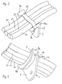
- Fig. 2 eine perspektivische Darstellung des Kabelhalters nach der
Figur 1 mit daran befestigten Kabeln, und - Fig. 3 eine perspektivische Darstellung des Kabelhalters nach der
Figur 1 in einer der Darstellung derFigur 1 in gegengesetzten Blickrichtung mit daran befestigten Kabeln.
- 1 shows a preferred embodiment of the cable holder according to the invention in a perspective view without cables attached to it,
- Fig. 2 is a perspective view of the cable holder of Figure 1 with cables attached, and
- Fig. 3 is a perspective view of the cable holder according to Figure 1 in one of the representation of Figure 1 in the opposite direction with cables attached.
Der erfindungsgemäße Kabelhalter 1 ist einstückig ausgebildet und umfaßt eine
Befestigungslasche 3 und eine wannenförmige Wulst 5. Die Wulst 5 weist einen
Wannenboden 8 und zwei daran am Winkel angeordnete Schenkel 9a, 9b auf.
Die Wulst 5 erstreckt sich in ihre Breite winklig und vorzugsweise rechtwinklig zur
Befestigungslasche 3, die als Ebene oder Platte ausgeführt ist und sich dabei von
den freien Enden 11a bzw. 11b der Schenkel 9a bzw. 9b zum freien Ende 12 der
Befestigungslasche 3 hin verjüngt. Die Befestigungslasche 3 geht an einer Seite
der Wulst in diese über und ist vorzugsweise mit dieser einstückig ausgebildet,
wodurch sich eine besonders günstige Herstellbarkeit ergibt. Im Bereich des freien
Endes 12 ist eine Bohrung oder ein Befestigungsloch 15 zur Befestigung der
Befestigungslasche 3 bzw. des Kabelhalters 1 an einer entsprechenden Stelle der
Umgebungsstruktur mittels üblichen Verbindungselementen vorgesehen.The
Das wulstseitige Ende der Befestigungslasche 3 ist so gestaltet, daß die
Befestigungslasche 3 über eine Kante 17 in die Wulst 5 übergeht. An die
Befestigungslasche 3 nahe der Kante 17 und im Bereich der Schenkel 9a, 9b ist
jeweils eine Nase oder ein Stift 20 vorgesehen, der sich senkrecht zu ebenen
Oberfläche 21, also in Richtung zur Breitenerstreckung der Wulst 5 erstreckt. Bei
der Befestigung der Befestigungslasche 3 an einer Umgebungsstruktur liegen die
beiden Nasen 20a, 20b an einer geeigneten Kantenlinie der Umgebungsstruktur
auf. Das durch die Bohrung 15 hindurchgehende Verbindungselement bildet
zusammen mit den an einer entsprechenden Kante aufliegenden Nasen 20a, 20b
eine stabile Halterung und insbesondere eine Abstützung gegen die Drehrichtung.
Mittels des die Bohrung durchfragenden Befestigungsmittels sowie durch die
Nasen 20a, 20b wird der erfindungsgemäße Kabelhalter 1 mit einfachen
Montagemitteln und geringem Aufwand in einer stabilen Weise an der
Fahrzeugstruktur befestigt.The bead-side end of the mounting tab 3 is designed so that the
Fastening tab 3 passes over an
Dabei muß die Umgebungstruktur einen regelmäßigen oder unregelmäßigen Durchbruch oder eine flache Kante aufweisen. Der regelmäßige Durchbruch kann eine Bohrung, eine Elipse oder ein anderer geometrisch gestalteter Durchgang sein.The surrounding structure must be regular or irregular Cut out or have a flat edge. The regular breakthrough can a hole, an ellipse, or other geometrically designed passage his.
Insgesamt ist der erfindungsgemäße Kabelhalter 1 als Y-Halter ausgestaltet. Die
Wannenweite liegt im Bereich zwischen 25 und 30 mm und die Wannentiefe
zwischen 12 und 18 mm. Die Ösen 7 sind jeweils vorzugsweise rechteckig
gebildet und haben eine Seitenlänge zwischen 3 und 10 mm. Dadurch ergibt sich
eine besonders günstige Befestigungsmöglichkeit von Kabeln 21 mittels
bekannter Kabelbinder 22.Overall, the
Nach der Montage des erfindungsgemäßen Kabelhalters an der
Umgebungstruktur wird das zu befestigende Kabel 21 in den Wannenboden 8
gelegt und mittels Kabelbinder 22 nach dem Stand der Technik, die durch die
Ösen 7 hindurchgeführt werden, auf dem Wannenboden 8 befestigt.After mounting the cable holder according to the invention on the
The
Das Material des erfindungsgemäßen Kabelhalters 1 ist Polyetheretherketon.
Dieses Material kann auch mit 10 bis 30 Masse% Glasfasern versehen sein,
wobei vorzugsweise 30 Masse-% Glasfasern vorgesehen sind.The material of the
Die Nasen 20a, 20b sind vorzugsweise an einer Stelle auf der Befestigungslasche
3 vorgesehen, daß deren Umfangslinie höchstens den halben Nasendurchmesser
von der Kante 17 entfernt liegt. Die Nasen 20a, 20b haben eine Länge zwischen
2 und 4 mm und vorzugsweise von 3 mm und einen Durchmesser von 2 bis 5 mm
und vorzugsweise von 2,5 mm. Die Nasen 20a, 20b sind vorzugsweise als Stifte
oder Zylinder ausgebildet und können jedoch auch eine andere gekrümmte
Außenstruktur haben, beispielsweise können sie abschnittsweise ellipsenförmig
gekrümmt sein im Bereich der Auflagefläche der Umgebungsstruktur.The lugs 20a, 20b are preferably at one point on the fastening tab
3 provided that the circumferential line at most half the nose diameter
from the
Die Wannenweite ist definiert als der Abstand zwischen den freien Enden 11a,
11b der Schenkel 9a, 9b, während die Wannentiefe als der Abstand zwischen der
Verbindungslinie zwischen dem freien Ende der Schenkel 9a, 9b und dem davon
in senkrechter Richtung entferntesten Punkt des Wannenbodens 6 definiert ist.The tub width is defined as the distance between the free ends 11a,
11b of the
Alternativ kann die Befestigungslasche 3 auch winklig zur Oberfläche des als
Auflagefläche für Kabel 21 dienenden Wannenbodens angeordnet sein. Eine
derartige Ausgestaltung hängt vom jeweiligen Anwendungsfall ab.Alternatively, the fastening tab 3 can also be angled to the surface of the
Support surface for
Claims (6)
dadurch gekennzeichnet,
characterized,
Applications Claiming Priority (2)
| Application Number | Priority Date | Filing Date | Title |
|---|---|---|---|
| DE10010933 | 2000-03-06 | ||
| DE10010933A DE10010933C1 (en) | 2000-03-06 | 2000-03-06 | Cable holder for fastening cables in vehicle structures has a fastening clip with a hole for fastening it with connector elements to a vehicle structure and a dish-shaped bulge to put the cable on forming one piece with the fastening clip. |
Publications (2)
| Publication Number | Publication Date |
|---|---|
| EP1133038A1 true EP1133038A1 (en) | 2001-09-12 |
| EP1133038B1 EP1133038B1 (en) | 2003-05-02 |
Family
ID=7633738
Family Applications (1)
| Application Number | Title | Priority Date | Filing Date |
|---|---|---|---|
| EP01104545A Expired - Lifetime EP1133038B1 (en) | 2000-03-06 | 2001-03-05 | Cable holder for fixing cables in a vehicule structure |
Country Status (5)
| Country | Link |
|---|---|
| US (1) | US6394399B2 (en) |
| EP (1) | EP1133038B1 (en) |
| AT (1) | ATE239309T1 (en) |
| DE (2) | DE10010933C1 (en) |
| ES (1) | ES2194803T3 (en) |
Cited By (3)
| Publication number | Priority date | Publication date | Assignee | Title |
|---|---|---|---|---|
| RU2531793C1 (en) * | 2013-04-19 | 2014-10-27 | Государственное Научное Учреждение "Объединенный Институт Машиностроения Национальной Академии Наук Беларуси" | Cable retainer |
| CN107276001A (en) * | 2016-04-07 | 2017-10-20 | 飞利浦灯具控股公司 | Cable is kept |
| RU2733222C1 (en) * | 2020-03-27 | 2020-09-30 | Акционерное общество «Информационные спутниковые системы» имени академика М.Ф.Решетнёва» | Method of fastening cable harness |
Families Citing this family (18)
| Publication number | Priority date | Publication date | Assignee | Title |
|---|---|---|---|---|
| SE0104284L (en) * | 2001-12-18 | 2003-06-19 | Volvo Lastvagnar Ab | mounting elements |
| US20030222184A1 (en) * | 2002-05-30 | 2003-12-04 | Hellermann Tyton Corporation | Axial oval mount for elongate article having a flexible tie |
| DE10236553B4 (en) * | 2002-08-08 | 2004-09-30 | Hilti Ag | Wiring harness fixing |
| US7083152B2 (en) * | 2002-11-07 | 2006-08-01 | Computer Network Technology Corporation | Method and apparatus for restraining a data cable |
| US20050279892A1 (en) * | 2004-06-17 | 2005-12-22 | Zdravko Kovac | Radiator hose bracket |
| US20090173843A1 (en) * | 2008-01-09 | 2009-07-09 | Toyota Motor Engineering & Manufacturing North America, Inc. | Mounting structures for wire harnesses |
| FR2949621B1 (en) * | 2009-09-03 | 2011-11-18 | Peugeot Citroen Automobiles Sa | DEVICE FOR MAINTAINING, AT DISTANCE FROM SURROUNDING PARTS OF A MOTOR VEHICLE, AT LEAST ONE ELECTRIC POWER CABLE OF AN ELECTRICAL EQUIPMENT OF THE VEHICLE |
| FR2952418B1 (en) | 2009-11-09 | 2012-01-20 | Airbus Operations Sas | SUPPORT FOR MAINTAINING LONG OBJECTS IN RELATION TO A STRUCTURE |
| GB201001002D0 (en) * | 2010-01-22 | 2010-03-10 | Airbus Operations Ltd | A bracket for attaching an electrical cable to a vehicle |
| CN103476530B (en) * | 2011-03-18 | 2016-10-05 | 影像行业公司 | Stackable clamp presss from both sides |
| JP5673451B2 (en) * | 2011-09-05 | 2015-02-18 | 住友電装株式会社 | Wire harness exterior |
| CN103917541B (en) | 2011-10-10 | 2016-08-17 | 弗·哈夫曼-拉罗切有限公司 | Antiviral compound |
| WO2014135912A1 (en) | 2013-03-04 | 2014-09-12 | Ludwig & Matthias Feil Gbr | Cable bracket with remote insertion and extraction facility |
| CN107317275B (en) * | 2016-04-26 | 2018-11-06 | 北京金风科创风电设备有限公司 | Cable mounting bracket, cable mounting device and wind generating set |
| US10690267B2 (en) * | 2018-07-16 | 2020-06-23 | Raytheon Technologies Corporation | Adjustable holding assembly |
| FR3095490B1 (en) * | 2019-04-29 | 2021-04-16 | Psa Automobiles Sa | MULTIFUNCTIONAL MOUNTING BRACKET FOR ATTACHING CONNECTION ELEMENTS TO A THERMAL ENGINE |
| GB2585032A (en) * | 2019-06-25 | 2020-12-30 | Talon Mfg Limited | Pipe clip |
| US11677222B1 (en) | 2021-12-28 | 2023-06-13 | Panduit Corp. | Winged cable mount |
Citations (2)
| Publication number | Priority date | Publication date | Assignee | Title |
|---|---|---|---|---|
| US3632069A (en) * | 1970-02-11 | 1972-01-04 | Panduit Corp | Bracket for mounting cable bundles in lightening holes |
| JPH10220649A (en) * | 1997-02-07 | 1998-08-21 | Burest Kogyo Kenkyusho Co Ltd | Cable support |
Family Cites Families (15)
| Publication number | Priority date | Publication date | Assignee | Title |
|---|---|---|---|---|
| US1462671A (en) * | 1921-07-05 | 1923-07-24 | Vrba John | Pipe or cable clamp |
| DE675892C (en) | 1936-02-15 | 1939-05-20 | Lorenz Akt Ges C | Cable bar |
| US2431379A (en) * | 1941-11-26 | 1947-11-25 | Adel Prec Products Corp | Snap clamp |
| US2427770A (en) * | 1941-11-26 | 1947-09-23 | Adel Prec Products Corp | Snap clip |
| US2342958A (en) * | 1942-07-06 | 1944-02-29 | Adel Prec Products Corp | Supporting clip for wires |
| DE1886744U (en) * | 1963-11-15 | 1964-01-30 | Dornier Werke Gmbh | FASTENING DEVICE FOR CABLES IN DIFFICULT POSITIONS. |
| DE1989458U (en) * | 1968-04-06 | 1968-07-18 | Hell Rudolf Dr Ing Fa | CABLE TAPE HOLDER. |
| DE3013750A1 (en) | 1980-04-10 | 1981-10-15 | Brown, Boveri & Cie Ag, 6800 Mannheim | Cable tension relief device for electric installations - has rail across cable insert with eyelets transverse to long axis for cable connectors |
| AU540604B2 (en) * | 1980-08-13 | 1984-11-29 | Bicc General Uk Cables Limited | Pipe or cable securing device |
| US4379537A (en) * | 1981-08-10 | 1983-04-12 | Whipple Patent Management Corporation | Cable hanger |
| DE9005666U1 (en) | 1990-05-18 | 1990-08-09 | Bauknecht Hausgeraete Gmbh, 7000 Stuttgart, De | |
| US5332179A (en) * | 1992-12-30 | 1994-07-26 | Panduit Corp. | 2-way box mount |
| DE9317299U1 (en) | 1993-11-05 | 1994-01-27 | Mannesmann Ag | Arrangement for the electrical contacting of cable shields |
| US5390883A (en) * | 1994-04-11 | 1995-02-21 | Songhurst; Ronald W. | Releasable mounting binder for wires and cables |
| FR2728757B1 (en) | 1994-12-21 | 1997-01-31 | Gec Alsthom Transport Sa | SYSTEM AND METHOD FOR FIXING LINES |
-
2000
- 2000-03-06 DE DE10010933A patent/DE10010933C1/en not_active Expired - Fee Related
-
2001
- 2001-03-05 AT AT01104545T patent/ATE239309T1/en not_active IP Right Cessation
- 2001-03-05 ES ES01104545T patent/ES2194803T3/en not_active Expired - Lifetime
- 2001-03-05 DE DE50100199T patent/DE50100199D1/en not_active Expired - Lifetime
- 2001-03-05 US US09/800,135 patent/US6394399B2/en not_active Expired - Fee Related
- 2001-03-05 EP EP01104545A patent/EP1133038B1/en not_active Expired - Lifetime
Patent Citations (2)
| Publication number | Priority date | Publication date | Assignee | Title |
|---|---|---|---|---|
| US3632069A (en) * | 1970-02-11 | 1972-01-04 | Panduit Corp | Bracket for mounting cable bundles in lightening holes |
| JPH10220649A (en) * | 1997-02-07 | 1998-08-21 | Burest Kogyo Kenkyusho Co Ltd | Cable support |
Non-Patent Citations (1)
| Title |
|---|
| PATENT ABSTRACTS OF JAPAN vol. 1998, no. 13 30 November 1998 (1998-11-30) * |
Cited By (3)
| Publication number | Priority date | Publication date | Assignee | Title |
|---|---|---|---|---|
| RU2531793C1 (en) * | 2013-04-19 | 2014-10-27 | Государственное Научное Учреждение "Объединенный Институт Машиностроения Национальной Академии Наук Беларуси" | Cable retainer |
| CN107276001A (en) * | 2016-04-07 | 2017-10-20 | 飞利浦灯具控股公司 | Cable is kept |
| RU2733222C1 (en) * | 2020-03-27 | 2020-09-30 | Акционерное общество «Информационные спутниковые системы» имени академика М.Ф.Решетнёва» | Method of fastening cable harness |
Also Published As
| Publication number | Publication date |
|---|---|
| DE10010933C1 (en) | 2001-08-16 |
| ATE239309T1 (en) | 2003-05-15 |
| ES2194803T3 (en) | 2003-12-01 |
| EP1133038B1 (en) | 2003-05-02 |
| US20010019093A1 (en) | 2001-09-06 |
| US6394399B2 (en) | 2002-05-28 |
| DE50100199D1 (en) | 2003-06-05 |
Similar Documents
| Publication | Publication Date | Title |
|---|---|---|
| EP1133038B1 (en) | Cable holder for fixing cables in a vehicule structure | |
| DE3600062C2 (en) | Drum unit | |
| DE10010934C2 (en) | Cable holder for fastening cables in vehicles | |
| DE3336607A1 (en) | DISTANCE PIECE | |
| EP0758728A1 (en) | Plastic supporting element | |
| DE102005048272B4 (en) | Connector for tent poles | |
| EP0483636A1 (en) | Plastics retaining element | |
| DE4036249A1 (en) | Duct made of e.g. steel sheet for accommodating electrical installation units - has lid type upper part permitting detachment and units for attaining potential equalisation between duct parts | |
| DE102018219651A1 (en) | Electronic control unit | |
| DE102012101614A1 (en) | Device for closing a housing of a connector | |
| DE3812093A1 (en) | SPACER FOR PANELS, ESPECIALLY FOR PCB | |
| DE2655127A1 (en) | CABLE CLAMP | |
| DE10318633B4 (en) | grommet | |
| DE2623898A1 (en) | HANGING DEVICE FOR LONG RANGE OBJECTS | |
| DE202017106399U1 (en) | Holding device and assembly with a holding device | |
| DE2735660C3 (en) | Fastening device, in particular for an on-board control panel of an automobile | |
| DE1790263C3 (en) | Distribution housing with a socket insert, e.g. a multi-pole wall socket insert with protective contact | |
| WO2018028879A1 (en) | Tolerance-compensation frame for joining around headlamps | |
| EP0399389A1 (en) | Cable duct | |
| DE77695T1 (en) | FASTENING ELEMENT WITH NUT HOLDER. | |
| DE2733200B2 (en) | Antenna socket | |
| DE1899122U (en) | SPACERS FOR REINFORCED CONCRETE REINFORCEMENT. | |
| EP0054115B1 (en) | Wire support, particularly for capacitive protection fences | |
| DE1247760B (en) | Fastening element for coil springs | |
| DE102020112255A1 (en) | Fastening system for pipes and cable harnesses in motor vehicles |
Legal Events
| Date | Code | Title | Description |
|---|---|---|---|
| PUAI | Public reference made under article 153(3) epc to a published international application that has entered the european phase |
Free format text: ORIGINAL CODE: 0009012 |
|
| AK | Designated contracting states |
Kind code of ref document: A1 Designated state(s): AT BE CH CY DE DK ES FI FR GB GR IE IT LI LU MC NL PT SE TR |
|
| AX | Request for extension of the european patent |
Free format text: AL;LT;LV;MK;RO;SI |
|
| 17P | Request for examination filed |
Effective date: 20020131 |
|
| AKX | Designation fees paid |
Free format text: AT BE CH CY DE DK ES FI FR GB GR IE IT LI LU MC NL PT SE TR |
|
| 17Q | First examination report despatched |
Effective date: 20020531 |
|
| GRAH | Despatch of communication of intention to grant a patent |
Free format text: ORIGINAL CODE: EPIDOS IGRA |
|
| GRAH | Despatch of communication of intention to grant a patent |
Free format text: ORIGINAL CODE: EPIDOS IGRA |
|
| RAP1 | Party data changed (applicant data changed or rights of an application transferred) |
Owner name: EADS DEUTSCHLAND GMBH |
|
| GRAA | (expected) grant |
Free format text: ORIGINAL CODE: 0009210 |
|
| AK | Designated contracting states |
Designated state(s): AT BE CH CY DE DK ES FI FR GB GR IE IT LI LU MC NL PT SE TR |
|
| PG25 | Lapsed in a contracting state [announced via postgrant information from national office to epo] |
Ref country code: NL Free format text: LAPSE BECAUSE OF FAILURE TO SUBMIT A TRANSLATION OF THE DESCRIPTION OR TO PAY THE FEE WITHIN THE PRESCRIBED TIME-LIMIT Effective date: 20030502 Ref country code: IE Free format text: LAPSE BECAUSE OF NON-PAYMENT OF DUE FEES Effective date: 20030502 Ref country code: TR Free format text: LAPSE BECAUSE OF FAILURE TO SUBMIT A TRANSLATION OF THE DESCRIPTION OR TO PAY THE FEE WITHIN THE PRESCRIBED TIME-LIMIT Effective date: 20030502 Ref country code: CY Free format text: LAPSE BECAUSE OF FAILURE TO SUBMIT A TRANSLATION OF THE DESCRIPTION OR TO PAY THE FEE WITHIN THE PRESCRIBED TIME-LIMIT Effective date: 20030502 Ref country code: FI Free format text: LAPSE BECAUSE OF FAILURE TO SUBMIT A TRANSLATION OF THE DESCRIPTION OR TO PAY THE FEE WITHIN THE PRESCRIBED TIME-LIMIT Effective date: 20030502 |
|
| REG | Reference to a national code |
Ref country code: GB Ref legal event code: FG4D Free format text: NOT ENGLISH |
|
| REG | Reference to a national code |
Ref country code: CH Ref legal event code: EP |
|
| REF | Corresponds to: |
Ref document number: 50100199 Country of ref document: DE Date of ref document: 20030605 Kind code of ref document: P |
|
| REG | Reference to a national code |
Ref country code: IE Ref legal event code: FG4D Free format text: GERMAN |
|
| PG25 | Lapsed in a contracting state [announced via postgrant information from national office to epo] |
Ref country code: GR Free format text: LAPSE BECAUSE OF FAILURE TO SUBMIT A TRANSLATION OF THE DESCRIPTION OR TO PAY THE FEE WITHIN THE PRESCRIBED TIME-LIMIT Effective date: 20030802 Ref country code: DK Free format text: LAPSE BECAUSE OF FAILURE TO SUBMIT A TRANSLATION OF THE DESCRIPTION OR TO PAY THE FEE WITHIN THE PRESCRIBED TIME-LIMIT Effective date: 20030802 |
|
| PG25 | Lapsed in a contracting state [announced via postgrant information from national office to epo] |
Ref country code: PT Free format text: LAPSE BECAUSE OF FAILURE TO SUBMIT A TRANSLATION OF THE DESCRIPTION OR TO PAY THE FEE WITHIN THE PRESCRIBED TIME-LIMIT Effective date: 20030804 |
|
| REG | Reference to a national code |
Ref country code: SE Ref legal event code: TRGR |
|
| GBT | Gb: translation of ep patent filed (gb section 77(6)(a)/1977) | ||
| NLV1 | Nl: lapsed or annulled due to failure to fulfill the requirements of art. 29p and 29m of the patents act | ||
| ET | Fr: translation filed | ||
| REG | Reference to a national code |
Ref country code: IE Ref legal event code: FD4D Ref document number: 1133038E Country of ref document: IE |
|
| PG25 | Lapsed in a contracting state [announced via postgrant information from national office to epo] |
Ref country code: LU Free format text: LAPSE BECAUSE OF NON-PAYMENT OF DUE FEES Effective date: 20040305 Ref country code: AT Free format text: LAPSE BECAUSE OF NON-PAYMENT OF DUE FEES Effective date: 20040305 |
|
| PLBE | No opposition filed within time limit |
Free format text: ORIGINAL CODE: 0009261 |
|
| STAA | Information on the status of an ep patent application or granted ep patent |
Free format text: STATUS: NO OPPOSITION FILED WITHIN TIME LIMIT |
|
| PG25 | Lapsed in a contracting state [announced via postgrant information from national office to epo] |
Ref country code: MC Free format text: LAPSE BECAUSE OF NON-PAYMENT OF DUE FEES Effective date: 20040331 Ref country code: BE Free format text: LAPSE BECAUSE OF NON-PAYMENT OF DUE FEES Effective date: 20040331 |
|
| 26N | No opposition filed |
Effective date: 20040203 |
|
| BERE | Be: lapsed |
Owner name: *EADS DEUTSCHLAND G.M.B.H. Effective date: 20040331 |
|
| PG25 | Lapsed in a contracting state [announced via postgrant information from national office to epo] |
Ref country code: CH Free format text: LAPSE BECAUSE OF NON-PAYMENT OF DUE FEES Effective date: 20050331 Ref country code: LI Free format text: LAPSE BECAUSE OF NON-PAYMENT OF DUE FEES Effective date: 20050331 |
|
| REG | Reference to a national code |
Ref country code: CH Ref legal event code: PL |
|
| PGFP | Annual fee paid to national office [announced via postgrant information from national office to epo] |
Ref country code: FR Payment date: 20120403 Year of fee payment: 12 |
|
| PGFP | Annual fee paid to national office [announced via postgrant information from national office to epo] |
Ref country code: DE Payment date: 20120323 Year of fee payment: 12 |
|
| PGFP | Annual fee paid to national office [announced via postgrant information from national office to epo] |
Ref country code: SE Payment date: 20120322 Year of fee payment: 12 Ref country code: GB Payment date: 20120322 Year of fee payment: 12 |
|
| PGFP | Annual fee paid to national office [announced via postgrant information from national office to epo] |
Ref country code: IT Payment date: 20120328 Year of fee payment: 12 |
|
| PGFP | Annual fee paid to national office [announced via postgrant information from national office to epo] |
Ref country code: ES Payment date: 20130326 Year of fee payment: 13 |
|
| REG | Reference to a national code |
Ref country code: SE Ref legal event code: EUG |
|
| PG25 | Lapsed in a contracting state [announced via postgrant information from national office to epo] |
Ref country code: SE Free format text: LAPSE BECAUSE OF NON-PAYMENT OF DUE FEES Effective date: 20130306 |
|
| GBPC | Gb: european patent ceased through non-payment of renewal fee |
Effective date: 20130305 |
|
| REG | Reference to a national code |
Ref country code: FR Ref legal event code: ST Effective date: 20131129 |
|
| REG | Reference to a national code |
Ref country code: DE Ref legal event code: R119 Ref document number: 50100199 Country of ref document: DE Effective date: 20131001 |
|
| PG25 | Lapsed in a contracting state [announced via postgrant information from national office to epo] |
Ref country code: FR Free format text: LAPSE BECAUSE OF NON-PAYMENT OF DUE FEES Effective date: 20130402 Ref country code: DE Free format text: LAPSE BECAUSE OF NON-PAYMENT OF DUE FEES Effective date: 20131001 Ref country code: GB Free format text: LAPSE BECAUSE OF NON-PAYMENT OF DUE FEES Effective date: 20130305 |
|
| PG25 | Lapsed in a contracting state [announced via postgrant information from national office to epo] |
Ref country code: IT Free format text: LAPSE BECAUSE OF NON-PAYMENT OF DUE FEES Effective date: 20130305 |
|
| REG | Reference to a national code |
Ref country code: ES Ref legal event code: FD2A Effective date: 20150428 |
|
| PG25 | Lapsed in a contracting state [announced via postgrant information from national office to epo] |
Ref country code: ES Free format text: LAPSE BECAUSE OF NON-PAYMENT OF DUE FEES Effective date: 20140306 |