EP1134501A1 - Smoke extracting hood - Google Patents
Smoke extracting hood Download PDFInfo
- Publication number
- EP1134501A1 EP1134501A1 EP01103258A EP01103258A EP1134501A1 EP 1134501 A1 EP1134501 A1 EP 1134501A1 EP 01103258 A EP01103258 A EP 01103258A EP 01103258 A EP01103258 A EP 01103258A EP 1134501 A1 EP1134501 A1 EP 1134501A1
- Authority
- EP
- European Patent Office
- Prior art keywords
- chimney
- extractor hood
- air
- rails
- housing
- Prior art date
- Legal status (The legal status is an assumption and is not a legal conclusion. Google has not performed a legal analysis and makes no representation as to the accuracy of the status listed.)
- Withdrawn
Links
Images


Classifications
-
- F—MECHANICAL ENGINEERING; LIGHTING; HEATING; WEAPONS; BLASTING
- F24—HEATING; RANGES; VENTILATING
- F24C—DOMESTIC STOVES OR RANGES ; DETAILS OF DOMESTIC STOVES OR RANGES, OF GENERAL APPLICATION
- F24C15/00—Details
- F24C15/20—Removing cooking fumes
- F24C15/2078—Removing cooking fumes movable
- F24C15/2085—Removing cooking fumes movable adjustable in height
-
- F—MECHANICAL ENGINEERING; LIGHTING; HEATING; WEAPONS; BLASTING
- F24—HEATING; RANGES; VENTILATING
- F24C—DOMESTIC STOVES OR RANGES ; DETAILS OF DOMESTIC STOVES OR RANGES, OF GENERAL APPLICATION
- F24C15/00—Details
- F24C15/20—Removing cooking fumes
- F24C15/2035—Arrangement or mounting of filters
Definitions
- the invention relates to an extractor hood, in particular one Kitchen extractor hood, with a hood shade that has a suction surface has, and one of a cutout in the hood screen in the operating position chimney projecting upwards, which in turn has a chimney housing and is preferably constructed with a frame, the frame window with horizontal bottom rails and upper rails as well as vertical housing edge rails includes, between which extend wall panels.
- Usual extractor hoods especially for the kitchen - for the exhaust air or for recirculation mode - generally have a hood screen and a shaft or fireplace, the fireplace for wall mounting three side walls and for an assembly as an island hood generally has four side walls.
- a blower section which is a blower with a contains motor drive and its housing one with the suction opening of the Hood-screen connected suction-side opening and a pressure-side air discharge opening
- extractor hood chimneys with a frame construction known DE-GM 299 16 895), which consist of parallel edge profile bars and transverse Struts exist between which plates are inserted.
- Extractor hoods with chimneys known (DE-GM 299 09 279), the walls of which Glass panels are in particular with decorative glass.
- the well-known extractor hoods However, there is room for improvement with regard to their chimney construction in terms of improved air extraction and in terms of improved Exchange and maintenance options.
- the chimney contains a blower section, which contains a blower with a motor drive in a housing and the housing of which is both connected to the intake opening of the hood screen suction-side opening as well as at least one further suction opening, the can be covered by an optionally adjustable grid, and a has pressure-side air discharge opening, preferably the blower section is inside the chimney and the additional suction opening with the free interior volume of the fireplace communicates, which in turn in at least one the walls of the fireplace housing an opening for air communication with the Environment.
- the extractor hood equipped with the internal fan has at least one of the wall panels or the top of the fireplace or the Hood a part that can be penetrated by an air flow, the one forms additional suction surface and on the inside of the chimney or hood screen communicates with the suction side of the fan in terms of air conduction.
- the Air intake through the chimney wall makes it interchangeable.
- an openable door is attached to one of the wall panels, or at least one of the wall panels can be removed by placing it in two insertion rails formed opposite rails of the frame window with limited mobility in the panel level between the rails is held and by a force in one of the guides with a depth of engagement is pressed, which is smaller than the degree of mobility of the wall panel between the rails.
- the suction surfaces for the room suction can both be chimney side walls as well as in particular with a chimney wall mounting Top, as well as surfaces with a corresponding construction of the hood screen be on the top of the screen.
- the extractor hood is a recirculating extractor hood is, at least one of the air-permeable wall panels is one Air outlet surface, the inside of which is air ducted with the pressure side of the Blower communicates and over which there is an exchangeable large-area filter Can extend, preferably the air outlet surface on its outside Plate with an air steering structure that the filtered clean air into a directs the desired direction.
- the air-permeable wall panel On the intake side, as far as the kitchen air intake affected by a wall panel connects to the air-permeable wall panel expediently again a large-area filter, for example a Cascade of a dishwasher-safe, wire mesh dirt and grease filter and a carbon filter plate, followed by an air guide structure to the blower, in particular an air funnel referred to as a "dome", which adapts the size of the suction surface to the size of a suction opening on the blower.
- a large-area filter for example a Cascade of a dishwasher-safe, wire mesh dirt and grease filter and a carbon filter plate
- an air guide structure to the blower in particular an air funnel referred to as a "dome"
- the blower in particular an air funnel referred to as a "dome"
- the dome can also be another air duct element between the dome and the blower lie like a channel or hose section.
- the chimney Extractor hood the removable wall panels or in one of the wall panels the openable door.
- the wall panels are conveniently through easy lifting and swiveling forward, removable from several removable panels at least one one to the outside has protruding handle, the easy lifting against spring force facilitated. If the other panels do not have this handle, they can after removing the first panel by mutual attack or with Raised and swung out with the help of an inside handle become.
- the bottom rail of the chimney frame is expediently one the channel that forms the guide and is open at the top for inserting the lower edge of the panel, which can be swung over this open channel, if the panel is pushed up against the spring force.
- the panel In the fully assembled state, the panel can simply be lifted by its weight the guide are held in the bottom rail. This proves itself with Transporting the extractor hood as a disadvantage, the panels could also start shaking and clinking. It is therefore expedient to lower it pressing force generated by a spring force member on the upper rail, wherein the vertical displaceability of the wall panel on the order of about corresponds to the maximum spring travel of the spring force element.
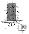
- FIG. 1 there is an extractor hood according to the invention from a screen 1 and a chimney 2.
- the screen has on its underside a suction opening 3, namely a horizontal large-area suction surface and carries control buttons 4 on its front.
- the fireplace is cuboid with rectangular or square cross-section, with rectangular chimney walls in the form of panels 5, at least some of which are lattice panels. These panels are held in a frame 6, which as vertical parts Has housing edge rails 7 and as horizontal parts at the lower end Has bottom rails 8 and upper rails 9 at the upper end.
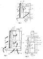
- the chimney contains, as shown in FIG. 2, exchangeable in the air duct tract emanating from the screen 1 a fat filter 10 and a carbon filter 11, further one - in Fig.
- Blower section 14 comprising suction-side opening, to which An air line 15 via an opening on the pressure side that is not visible in the drawing connected to an extractor hood via an air duct installation leads to a wall box that takes the air out of the room.
- the Blower section 14 includes an electric motor and a compressor.
- extractor hood has the front panel in its grille a decor 16, here in the form of a tendril pattern.
- the cuboid housing 12 is on one (Fig. 1) or more sides, in addition to the downward opening 13, each with another Provided suction opening 17 which is cut one of its walls and over which the fan sucks air from the interior of the fireplace 2 and additionally in the air line 15 presses.
- the suction opening 17 can be on one or more the housing walls are formed, have any shape and with a filter, for. B. a grease filter or the like. It is especially with an island hood advantageous if two suction openings 17 face each other on the housing.
- the kitchen on the one hand, rising from the stove through the suction opening 3 of the hood screen 1 Air 18 and on the other hand sucked off through the grid panels 5 kitchen air 19.
- the kitchen air 19 consists to a large extent also of air from the cooktop rises, but flows past the hood screen.
- the kitchen air 19 penetrates, as shown in FIG. 2, the respective grid panel 5 and one behind this arranged plate-shaped filter cassette 22, from which the air over as well as through the suction opening 17 from the blower section 14 and then is carried away with the exhaust air through the exhaust air line 15.
- the large-area filter cassette 22 enables a very effective air filtering. It can be a dust and grease filter, a carbon filter or a stratification of these two filters.
- Fig. 1 only a single suction opening 17 is shown in the housing 12, such suction openings are, however, on all side surfaces and / or on the Top of the housing 12 possible.
- Fig. 3 shows a modification in that the dome 24 by a Chamber 31 separating partition 32 is replaced, the two additional fans 33 carries, which controllably transport the kitchen air 19 into the exhaust duct 15.
- the grid 26, which is integrated in the panel here in comparison to FIG. 2, and the 3 are used to distribute the suction power between air flows 18 and 19.
- Fig. 4 illustrates a further modified embodiment in which the fan section 14 outside the actual extractor hood, namely in the course of the exhaust duct 15, for example in the wall box.
- the air duct is divided into modules 36 and one of the modules is the grid panel 5, the dome 24 and the additional blower 33 Kitchen room air 19 initiated.
- the kitchen air is 19 not passed through a filter arranged on the grid panel 5, but can be present in the modules 36 filter in a manner not shown.
- Blower section 14 located outside the chimney can be another Suction opening analogous to the suction opening 17 of FIG. 1 to be present on Extract room air from the location of the blower section.
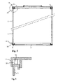
- Filter cartridges as illustrated for example in Fig. 2 and 3 as plates need to be cleaned and / or replaced with new filter cartridges be interchangeable. Depending on the load, such an exchange can, for example fall due after a few months. Even with airtight wall panels occasional cleaning is desirable.
- 5 and 6 show a construction, which facilitates the exchange of the filters or panels in that the Wall panels 5 taken out of the frame 6 in total and again can be inserted. There are various options for this, in Figs 5 and 6 illustrates the possibility that the panel in question 5, the one Grid panel or also a plate panel, for example a decorative glass plate can, in a formed on the bottom rail 8 lower groove 38 and one on the upper rail 9 formed upper channel 39 is used in each case.
- a leaf spring 40 is installed, which presses the panel 5 downwards.
- the gutter depth the upper groove 39 is greater than the groove depth of the lower groove 38, and by pushing the panel 5 upward against the compressive force of the spring 40
- the lower end of the panel 5 becomes the lower groove 38 lifted out and can be swung forward and out of the frame 6 be removed. So far on the panel 5 filter cassettes or other filter plates mounted, they can then be removed and replaced. The The panel itself can be cleaned without difficulty. Finally it will be back used in the frame 6.
- the handle 41 is designed so that it can also take on additional functions can, for example, as a hanger for towels and devices.
- the leaf spring 40 may also be missing Panel 5 will then be in the operating position of the extractor hood Weight held in the lower groove 38.
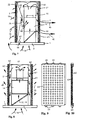
- Fig.n 7 and 8 show schematically and with an open front, one each modified extractor hood, namely a recirculation hood, the filtered and returns cleaned air 45 to the kitchen room. It again shows the umbrella 1, the suction opening 3, the blower section 14 and above the air line 15.
- the hoods of Fig.n 7 and 8 give the sucked air 18 and (Fig. 7) 19 which in Shape of arrows is indicated, filtered and optionally (Fig. 7) by a Fragrance dispenser 60 refined to the interior, and that is the air through Air deflection bends 61 transported to large-area filter cassettes 62, each form an entire chimney wall and from perforated plates 63 for example Stainless steel.
- the available large area of the filter cassettes has the consequence that at every point the approaching air, which is on a large flow cross-section, only relatively slowly through the filter cassette flows through and can therefore be filtered very effectively there.
- one of the chimney wall panels 5 is comparable to FIG. 2 Suction surface for the kitchen air 19 and another panel 5 'an air discharge surface; 8, both opposite wall panels are air discharge surfaces.
- the filter chimney walls the main components of which the filter cassettes 62 and the perforated plates 63 are, as a whole, in the Chimney frame interchangeably hung, in this embodiment clipped in, on the one hand pins 64, on the other hand spring clips 65 and corresponding complementary parts serve in the permanently installed fireplace frame.
- the filter cartridges are carbon filters that are identified in the drawing by dot hatching are. However, this is not to be understood as restrictive.
- the filters can be carbon filter cartridges, Charcoal mats and general filters of all kinds, possibly supplemented through grease filters. You can use a simple tool in their Bracket raised and then removed.
- the perforated sheets can for example also made of aluminum or in simple versions made of plastic consist.
- a filter saturation indicator is used to monitor the filter status 66, which are determined on the basis of a pressure meter 67 with increasing Filter impenetrability of increasing pressure in the chamber of the hood, that the next filter change is due (Fig. 7).
- Figs. 11 and 12 show a step plate 69 with blow-out holes 70, which are directed upwards are. 12 there is an increased air discharge in the upper region of the fireplace thereby achieved that through larger blow-out holes 70 there is a larger flow cross-section is available as in the lower part of the fireplace.
- the chimney wall has a fold-out wall with a grille 71. Behind the grille there is a replaceable (not shown) filter cassette.
- FIGS. 14 to 19 illustrate various possibilities, for example the walls of the chimney of the extractor hood partly with filter cassettes and partly with wall panels, which can be decorative panels, for example.
- Fig. 14 shows a wall hood, the chimney is open at the back because it is there leaning against the wall of the room. All three other chimney walls are with filter cassettes busy. 15, only the side walls are covered with filter cartridges and the front wall is formed by a decorative panel; while this decorative panel The filter cartridges are inserted and therefore not easily interchangeable with their brackets clipped in for replacement, cleaning, etc. and thus easy to remove and reinsert.
- Fig. 15 shows a constellation that is particularly for one between furniture located extractor hood is suitable, with side wall panels and a front Filter cassette;
- Fig. 17 shows an example of the possibility of filtering only laterally To release air.
- the Fig.n 18 and 19 show possibilities for island hoods, that is are not installed on the wall.
- Fig. 18 there are filter cartridges all around used, in Fig. 19 only on two opposite side surfaces.
- the door 73 can be different Serve purposes, for example to replace filter cartridges. Farther it can be used to match a drawer module located behind it accessible to the blower section 14 designed as a separate module make and lock again.
- a corresponding extractor hood is with their inner parts shown in Figs. 21 and 22 described later. But Even with permanently installed interior parts, the door 73 can be useful for access to facilitate the engine and control for service work, etc. especially with extractor hoods that are complete with kitchen cabinets etc. are converted. This may result in an expansion of the entire device be avoided for repair.
- the door is of course not on the one shown Limited execution. In particular, it can cover the entire front of the fireplace Claim, it can be a flap that can be pivoted about any axis or it can also be a releasable fixation means such as clips on the fireplace Wall plate.
- Fig.n 21 and 22 show the extractor hood, in which the fan section 14 represents a drawer module, which is indicated by the indicated door 73 of the Chimney frame 6 insertable on rails 74 and inside (in the drawing Fixing screws (not shown) can be fixed.
- a Control box 75 in the built in the fireplace frame 6 in this embodiment Fastening section used and fastened there at 76. in the Chimney frames 6 are plugs, not shown, for detachable at suitable points The removable module is attached.
- the control box 75 is via cables and plugs (not visible in FIG. 21) to the power and control lines connected to the hood.
- the door 73 closed.
- the rails in the drawer can also be used be arranged at the top and the module be hung there.
- FIG. 21 A further detail is shown in FIG. 21, namely an intermediate frame 79, which represents another detachable module and in one at this Embodiment formed below the chimney 2 at the bottom of the frame 6
- Mounting groove 80 can be inserted or clipped with a rib 81 and on the opposite side can be screwed with the help of a mounting flange 82.
- the intermediate frame 79 has another at its sloping lower edge Mounting flange on that of the attachment of the screen 1 in an oblique arrangement serves. As a result, the inclined hood screen assembly is useful in some cases possible.
- 23 to 26 illustrate embodiments of the invention Extractor hood, which is characterized by different fireplace designs award;
- 23 is an exhaust hood with kitchen room suction on upper end of one of the wall panels;
- Fig. 24 is a recirculation hood with additional Kitchen room extraction through special air holes in the fireplace, the same 25 and FIG. 26 such a circulating air hood with large-area lattice panels, which also have a decorative design.
- FIGS. 27 to 29 show variants to illustrate the possible ones Variety of constructions according to the invention.
- Fig. 27 shows an extraction of kitchen air via one in one of the Wall panels 5 attached suction opening, which is screwed on Cover plate 85 is covered.
- a ring arrangement of Holes 86 which are in turn covered by an identical ring arrangement having rotary plate 87.
- the flow cross section set By rotating the rotary plate 87, the flow cross section set, the arrangement thus fulfills the function of the grid 26 of Fig. 2.
- a filter cassette is attached can be replaced after unscrewing the plate 85.
- Fig. 28 shows in section an embodiment of the panel 5, with a cross hinge 89 extending therethrough and a hinged opening provided with air holes Part 90 of the panel, on the inside of the chimney in trough-shaped rails that are on its side edges and its lower edge are formed, the carbon filter 12 is inserted interchangeably from above.
- the panel 5 shown in Fig. 29 has a frame 92 in which the filter cartridge 22 is used with a combined fat and carbon filter.
- the frame 92 forms on three sides rails 93 and is open on a fourth side 94, so that there Filter cartridge can be pushed in and out.
Landscapes
- Engineering & Computer Science (AREA)
- Chemical & Material Sciences (AREA)
- Combustion & Propulsion (AREA)
- Mechanical Engineering (AREA)
- General Engineering & Computer Science (AREA)
- Ventilation (AREA)
- Filtering Of Dispersed Particles In Gases (AREA)
Abstract
Description
Die Erfindung bezieht sich auf eine Dunstabzugshaube, insbesondere eine Küchen-Dunstabzugshaube, mit einem Haubenschirm, der eine Ansaugfläche aufweist, und einem von einem Ausschnitt im Haubenschirm in der Betriebsstellung nach oben abstehenden Kamin, der seinerseits ein Kamingehäuse aufweist und vorzugsweise mit einem Gestellrahmen aufgebaut ist, der Rahmenfenster mit horizontalen Bodenschienen und oberen Schienen sowie vertikalen Gehäusekanten-Schienen umfaßt, zwischen denen sich Wandpaneele erstrecken.The invention relates to an extractor hood, in particular one Kitchen extractor hood, with a hood shade that has a suction surface has, and one of a cutout in the hood screen in the operating position chimney projecting upwards, which in turn has a chimney housing and is preferably constructed with a frame, the frame window with horizontal bottom rails and upper rails as well as vertical housing edge rails includes, between which extend wall panels.
Übliche Dunstabzugshauben speziell für den Küchenbetrieb - für den Abluft- oder für den Umluftbetrieb - weisen generell einen Haubenschirm und einen Schacht oder Kamin auf, wobei der Kamin für eine Wandmontage drei Seitenwände und für eine Montage als Inselhaube im allgemeinen vier Seitenwände hat. Im Kamin befindet sich ein Gebläseabschnitt, der in einem Gehäuse ein Gebläse mit einem motorischen Antrieb enthält und dessen Gehäuse eine mit der Einsaugöffnung des Haubenschirms verbundene saugseitige Öffnung und eine druckseitige Luftabgabeöffnung aufweist Es sind Dunstabzugshaubenkamine mit einer Rahmenkonstruktion bekannt (DE-GM 299 16 895), die aus parallelen Kanten-Profilstäben und querverlaufenden Streben besteht, zwischen denen Platten eingelegt sind. Es sind auch Dunstabzugshauben mit Kaminen bekannt (DE-GM 299 09 279), deren Wände Glaspaneele insbesondere mit Dekorglas sind. Die bekannten Dunstabzugshauben sind jedoch hinsichtlich ihrer Kaminkonstruktion noch verbesserungsfähig, und zwar im Hinblick auf eine verbesserte Luftabsaugung und im Hinblick auf verbesserte Austausch- und Wartungsmöglichkeiten.Usual extractor hoods especially for the kitchen - for the exhaust air or for recirculation mode - generally have a hood screen and a shaft or fireplace, the fireplace for wall mounting three side walls and for an assembly as an island hood generally has four side walls. In the fireplace there is a blower section, which is a blower with a contains motor drive and its housing one with the suction opening of the Hood-screen connected suction-side opening and a pressure-side air discharge opening There are extractor hood chimneys with a frame construction known (DE-GM 299 16 895), which consist of parallel edge profile bars and transverse Struts exist between which plates are inserted. They are too Extractor hoods with chimneys known (DE-GM 299 09 279), the walls of which Glass panels are in particular with decorative glass. The well-known extractor hoods However, there is room for improvement with regard to their chimney construction in terms of improved air extraction and in terms of improved Exchange and maintenance options.
Durch die Erfindung sollen verbesserte Luftabsaugmöglichkeiten und eine verbesserte Wartungsmöglichkeit und Austauschmöglichkeit für Zier- oder Verbrauchsteile geschaffen werden. Hierzu enthält der Kamin einen Gebläseabschnitt, der in einem Gehäuse ein Gebläse mit einem motorischen Antrieb enthält und dessen Gehäuse sowohl eine mit der Einsaugöffnung des Haubenschirms verbundene saugseitige Öffnung als auch noch wenigstens eine weitere Ansaugöffnung, die durch ein gegebenenfalls verstellbares Gitter überdeckt sein kann, und eine druckseitige Luftabgabeöffnung aufweist, wobei vorzugsweise der Gebläseabschnitt sich innerhalb des Kamins befindet und die zusätzliche Ansaugöffnung mit dem freien Innenvolumen des Kamins kommuniziert, der seinerseits in wenigstens einer der Wände des Kamingehäuses eine Öffnung zur Luftkommunikation mit der Umgebung hat. Die mit dem internen Gebläse ausgestattete Dunstabzugshaube weist wenigstens eines der Wandpaneele oder die Oberseite des Kamins oder des Haubenschirms einen durch eine Luftströmung durchsetzbaren Teil auf, der eine zusätzliche Ansaugfläche bildet und an der Kamin- bzw. Haubenschirm-Innenseite luftleitungsmäßig mit der Saugseite des Gebläses kommuniziert. Speziell die Luftansaugung auch durch die Kaminwand macht deren Austauschbarkeit erwünscht. Hierzu ist an einem der Wandpaneele eine aufmachbare Türe angebracht, oder ist wenigstens eines der Wandpaneele herausnehmbar, indem es in zwei an gegenüberliegenden Schienen des Rahmenfensters gebildete Einsteckführungen mit einer begrenzten Beweglichkeit in der Paneelebene zwischen den Schienen gehalten ist und durch eine Kraft in eine der Führungen mit einer Eingreiftiefe gedrückt ist, die kleiner ist als das Maß der Beweglichkeit des Wandpaneels zwischen den Schienen. Hierdurch ergeben sich einerseits die Möglichkeit für eine Küchenraumabsaugung im Bereich oberhalb des Haubenschirms über großflächige Filter, was sowohl im Abluftbetrieb als auch im Umluftbetrieb neue Möglichkeiten schafft, und andererseits die Möglichkeit eines leichten Austauschs sowohl dieser Filterplatten als auch gegebenenfalls weiterer Platten beispielsweise zur Reinigung oder bei Dekorpaneelen zur Abwechslung, sowie eines Zugangs zur innerhalb des Kamins installierten Technik.The invention aims to improve air extraction options and a improved maintenance and replacement options for decorative or consumable parts be created. For this purpose, the chimney contains a blower section, which contains a blower with a motor drive in a housing and the housing of which is both connected to the intake opening of the hood screen suction-side opening as well as at least one further suction opening, the can be covered by an optionally adjustable grid, and a has pressure-side air discharge opening, preferably the blower section is inside the chimney and the additional suction opening with the free interior volume of the fireplace communicates, which in turn in at least one the walls of the fireplace housing an opening for air communication with the Environment. The extractor hood equipped with the internal fan has at least one of the wall panels or the top of the fireplace or the Hood a part that can be penetrated by an air flow, the one forms additional suction surface and on the inside of the chimney or hood screen communicates with the suction side of the fan in terms of air conduction. Especially the Air intake through the chimney wall makes it interchangeable. For this purpose, an openable door is attached to one of the wall panels, or at least one of the wall panels can be removed by placing it in two insertion rails formed opposite rails of the frame window with limited mobility in the panel level between the rails is held and by a force in one of the guides with a depth of engagement is pressed, which is smaller than the degree of mobility of the wall panel between the rails. On the one hand, this creates the possibility for one Kitchen extraction in the area above the hood screen over large areas Filters, which offer new possibilities in both exhaust air and recirculation mode creates, and on the other hand the possibility of an easy exchange of both Filter plates and possibly other plates, for example for cleaning or for decorative panels for a change, as well as access to the inside of the Chimneys installed technology.
Die Ansaugflächen für die Raumabsaugung können hierbei sowohl Kamin-Seitenwände als auch insbesondere bei einer Kamin-Wandmontage dessen Oberseite, als auch bei entsprechender Konstruktion des Haubenschirms Flächen auf der Schirmoberseite sein. Wenn die Dunstabzugshaube eine Umluft-Dunstabzugshaube ist, ist wenigstens eines der luftdurchsetzbaren Wandpaneele eine Luftaustrittsfläche, deren Innenseite luftleitungsmäßig mit der Druckseite des Gebläses kommuniziert und über die sich ein austauschbares großflächiges Filter erstrecken kann, wobei vorzugsweise die Luftaustrittsfläche an ihrer Außenseite eine Platte mit einer Luftlenkstruktur aufweist, die die gefilterte saubere Luft in eine gewünschte Richtung lenkt. Ansaugseitig, soweit die Küchenraumluftansaugung durch ein Wandpaneel betroffen ist, schließt sich an das luftdurchlässige Wandpaneel zweckmäßigerweise wieder ein großflächiges Filter, beispielsweise eine Kaskade eines spülmaschinengeeigneten, aus Drahtgeflecht bestehenden Schmutz- und Fettfilters und einer Kohlefilterplatte, und an diese anschließend eine Luftleitstruktur zum Gebläse an, insbesondere ein als "Dom" bezeichneter Lufttrichter, der die Größe der Ansaugfläche an die Größe einer Ansaugöffnung am Gebläse anpaßt. Zwischen dem Dom und dem Gebläse kann auch noch ein weiteres Luftleitungs-element wie ein Kanal- oder Schlauchabschnitt liegen.The suction surfaces for the room suction can both be chimney side walls as well as in particular with a chimney wall mounting Top, as well as surfaces with a corresponding construction of the hood screen be on the top of the screen. If the extractor hood is a recirculating extractor hood is, at least one of the air-permeable wall panels is one Air outlet surface, the inside of which is air ducted with the pressure side of the Blower communicates and over which there is an exchangeable large-area filter Can extend, preferably the air outlet surface on its outside Plate with an air steering structure that the filtered clean air into a directs the desired direction. On the intake side, as far as the kitchen air intake affected by a wall panel connects to the air-permeable wall panel expediently again a large-area filter, for example a Cascade of a dishwasher-safe, wire mesh dirt and grease filter and a carbon filter plate, followed by an air guide structure to the blower, in particular an air funnel referred to as a "dome", which adapts the size of the suction surface to the size of a suction opening on the blower. There can also be another air duct element between the dome and the blower lie like a channel or hose section.
Die an den Wandpaneelen anliegenden Filterplatten müssen von Zeit zu Zeit regeneriert bzw. erneuert werden. Hierzu hat gemäß der Erfindung der Kamin der Dunstabzugshaube die herausnehmbaren Wandpaneele oder in einem der Wandpaneele die aufmachbare Türe. Die Wandpaneele sind zweckmäßigerweise durch leichtes Anheben und Herausschwenken nach vorne herausnehmbar, wobei von mehreren herausnehmbaren Paneelen wenigstens eines einen nach außen vorstehenden Handgriff aufweist, der das leichte Anheben gegen Federkraft erleichtert. Soweit die anderen Paneele diesen Handgriff nicht haben, können sie nach dem Herausnehmen des ersten Paneels durch beiderseitigen Angriff oder mit Hilfe eines innen angebrachten Handgriffs angehoben und herausgeschwenkt werden. Die Bodenschiene des Kaminrahmens ist hierbei zweckmäßigerweise eine die Führung bildende, nach oben offene Rinne zum Einlegen des unteren Rands des Paneels, der über diese offene Rinne hinweggeschwenkt werden kann, wenn das Paneel entgegen der Federkraft nach oben gedrückt ist.The filter plates on the wall panels have to be replaced from time to time be regenerated or renewed. For this purpose, according to the invention, the chimney Extractor hood the removable wall panels or in one of the wall panels the openable door. The wall panels are conveniently through easy lifting and swiveling forward, removable from several removable panels at least one one to the outside has protruding handle, the easy lifting against spring force facilitated. If the other panels do not have this handle, they can after removing the first panel by mutual attack or with Raised and swung out with the help of an inside handle become. The bottom rail of the chimney frame is expediently one the channel that forms the guide and is open at the top for inserting the lower edge of the panel, which can be swung over this open channel, if the panel is pushed up against the spring force.
Im fertig montierten Zustand kann das Paneel einfach durch sein Gewicht in der Führung in der Bodenschiene gehalten werden. Dies erweist sich aber beim Transport der Dunstabzugshaube als nachteilig, außerdem könnten die Paneele zu rütteln und zu klirren beginnen. Zweckmäßigerweise wird deshalb die nach unten drückende Kraft durch ein Federkraftglied an der oberen Schiene erzeugt, wobei die vertikale Verschieblichkeit des Wandpaneels größenordnungsmäßig etwa dem maximalen Federweg des Federkraftglieds entspricht.In the fully assembled state, the panel can simply be lifted by its weight the guide are held in the bottom rail. This proves itself with Transporting the extractor hood as a disadvantage, the panels could also start shaking and clinking. It is therefore expedient to lower it pressing force generated by a spring force member on the upper rail, wherein the vertical displaceability of the wall panel on the order of about corresponds to the maximum spring travel of the spring force element.
Diese Herausnehmbarkeit der Wandpaneele oder auch die in einem der Wandpaneele sitzende, zu öffnende Türe sind nicht nur zum Austausch von Filterplatten vorteilhaft, sondern auch zum Austausch luftundurchlässiger Wandpaneele. Außerdem ergibt sich die Möglichkeit, daß Module der in den Kamin eingebauten Technik ein- und ausbaubar sind und Wartungs- und Reparaturarbeiten im Kamin durchgeführt werden können. Beispielsweise kann, wenn der Kamin einen Lüftergehäuseabschnitt umfaßt, der das Gebläse und einen damit verbundenen Motor enthält, dieser Abschnitt schubladenartig in einen Teil des den Kamin bildenden Rahmens eingeschoben sein und durch die Fläche des herausnehmbaren Wandpaneels bzw. der Türe aus- und einfahrbar sein.This removability of the wall panels or that in one of the Sitting, opening wall panels are not just for exchanging Filter plates advantageous, but also for the exchange of airtight wall panels. There is also the possibility that modules of the built in the fireplace Technology can be installed and removed and maintenance and repair work in the Fireplace can be carried out. For example, if the fireplace is a Fan housing section includes the fan and an associated Engine contains this section drawer-like in part of the chimney forming frame inserted and through the surface of the removable Wall panels or the door can be extended and retracted.
Weitere Einzelheiten, Vorteile und Weiterbildungen der Erfindung ergeben sich aus der folgenden Beschreibung bevorzugter Ausführungsbeispiele unter Bezugnahme auf die Zeichnung. Es zeigen:
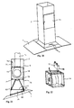
- Fig. 1
- eine perspektivische Darstellung einer Küchen-Dunstabzugshaube mit Herd- und Raumluftabsaugung;
- Fig. 2
- in schematischer Darstellung wesentliche Teile einer Dunstabzugshaube der Bauart nach Fig. 1 bei geöffneter Vorderseite;
- Fig. 3
- eine Darstellung entsprechend Fig. 2 einer abgewandelten Ausführung;
- Fig. 4
- wiederum in schematischer Darstellung entsprechend Fig. 2 eine abgewandelte Ausführung;
- Fig. 5
- in vergrößertem Maßstab einen Vertikalschnitt durch eine abgewandelte Ausführung eines Kamins einer Dunstabzugshaube, unter spezieller Darstellung seines oberen und unteren Endes;
- Fig. 6
- eine Einzelheit aus Fig. 5;
- Fig. 7
- eine Darstellung entsprechend Fig. 2 einer Umluftdunstabzugshaube;
- Fig. 8
- in schematischer Vorderansicht mit offener Vorderseite eine andere Ausführung einer Umluft-Dunstabzugshaube;
Fig.n 9 und 10- in zwei aufeinander senkrechten Betrachtungsrichtungen eine bei der Haube von Fig. 8 verwendete Filterkassette mit Halterung;
Fig.n 11 bis 13- jeweils in Vorder- und Seitenansicht weitere Ausführungen von Filterkassetten-Halterungen mit Ausblasöffnungen;
Fig.n 14 bis 19- schematische Horizontalschnitte durch unterschiedliche Ausführungen von Dunstabzugshauben-Kaminen, mit Filterkassetten und Wandplatten;
- Fig. 20
- in perspektivischer Darstellung eine weitere Ausführungsform;
- Fig. 21
- in schematischer Darstellung entsprechend Fig. 2 eine weitere Ausführungsform;
- Fig. 22
- in perspektivischer Darstellung Teile der Dunstabzugshaube von Fig. 21;
- Fig.n 23 bis 26
- Illustrationen verschiedener erfindungsgemäßer Dunstabzugshauben;
- Fig. 27
- in perspektivischer Darstellung das obere Ende eines Kamins gemäß einer abgewandelten Ausführung;
- Fig. 28
- einen Vertikalschnitt durch eine Vorderwand eines Kamins gemäß einer weiterhin abgewandelten Ausführung;
- Fig. 29
- in perspektivischer Darstellung eine Filterkassette in einem Wandpaneel.
- Fig. 1
- a perspective view of a kitchen extractor hood with stove and room air extraction;
- Fig. 2
- a schematic representation of essential parts of an extractor hood of the type of Figure 1 with the front open.
- Fig. 3
- a representation corresponding to Figure 2 of a modified embodiment.
- Fig. 4
- again in a schematic representation corresponding to FIG. 2, a modified embodiment;
- Fig. 5
- on an enlarged scale a vertical section through a modified version of a chimney of an extractor hood, with a special representation of its upper and lower end;
- Fig. 6
- a detail from Fig. 5;
- Fig. 7
- a representation corresponding to Figure 2 of a ventilator hood;
- Fig. 8
- in a schematic front view with an open front, another version of a forced-air extractor hood;
-
Fig.n - in two mutually perpendicular viewing directions a filter cassette with holder used in the hood of FIG. 8;
-
Fig.n 11 to 13 - each in front and side view further versions of filter cassette holders with blow-out openings;
-
Fig.n 14 to 19 - schematic horizontal sections through different designs of extractor hood chimneys, with filter cassettes and wall plates;
- Fig. 20
- another embodiment in perspective;
- Fig. 21
- 2 shows a further embodiment in a schematic representation;
- Fig. 22
- in perspective view parts of the extractor hood of Fig. 21;
- Fig.n 23 to 26
- Illustrations of various extractor hoods according to the invention;
- Fig. 27
- in perspective the upper end of a fireplace according to a modified version;
- Fig. 28
- a vertical section through a front wall of a fireplace according to a further modified embodiment;
- Fig. 29
- in perspective a filter cartridge in a wall panel.
Wie aus Fig. 1 ersichtlich ist, besteht eine erfindungsgemäße Dunstabzugshause
aus einem Schirm 1 und einem Kamin 2. Der Schirm weist an seiner Unterseite
eine Einsaugöffnung 3, nämlich eine horizontale großflächige Ansaugfläche, auf
und trägt an seiner Vorderseite Steuerknöpfe 4. Der Kamin ist quaderförmig mit
rechteckigem oder quadratischem Querschnitt gestaltet, mit rechteckigen Kaminwänden
in Form von Paneelen 5, von denen mindestens einige Gitterpaneele sind.
Diese Paneele sind in einem Rahmen 6 gehalten, der als senkrechte Teile
Gehäusekanten-Schienen 7 aufweist und als horizontale Teile am unteren Ende
Bodenschienen 8 und am oberen Ende obere Schienen 9 aufweist. Der Kamin
enthält, wie Fig. 2 zeigt, im vom Schirm 1 ausgehenden Luftleitungstrakt austauschbar
ein Fettfilter 10 und ein Kohlefilter 11, weiterhin einen - in Fig. 1 zusätzlich
separat dargestellten - ein Gehäuse 12 mit einer mit der Einsaugöffnung 3 kommunizierenden
saugseitigen Öffnung umfassenden Gebläseabschnitt 14, an den sich
über eine in der Zeichnung nicht sichtbare druckseitige Öffnung eine Luftleitung 15
anschließt, die bei einer Abluft-Dunstabzugshaube schließlich über eine Luftleit-installation
zu einem Mauerkasten führt, der die Luft aus dem Raum abführt. Der
Gebläseabschnitt 14 enthält einen Elektromotor und einen Verdichter. Bei der in Fig.
1 dargestellten Dunstabzugshaube weist das vorderste Paneel in seinem Gitter
einen Dekor 16, hier in Form eines Rankenmusters, auf.As can be seen from Fig. 1, there is an extractor hood according to the invention
from a
Das quaderförmige Gehäuse 12 ist an einer (Fig. 1) oder mehreren Seiten,
zusätzlich zur nach unten gerichteten Öffnung 13, noch mit jeweils einer weiteren
Ansaugöffnung 17 versehen, die ein eine seiner Wände geschnitten ist und über
die das Gebläse Luft aus dem Innenraum des Kamins 2 ansaugt und zusätzlich in
die Luftleitung 15 drückt. Die Ansaugöffnung 17 kann an einer oder an mehreren
der Gehäusewände gebildet sein, beliebige Form haben und mit einem Filter, z. B.
einem Fettfilter, o. dgl. versehen sein. Insbesondere bei einer Inselhaube ist es
vorteilhaft, wenn zwei Ansaugöffnungen 17 sich am Gehäuse gegenüberliegen.The
Wie in den Fig.n 1 und 2 durch Pfeile angedeutet ist, wird aus der Küche
einerseits durch die Einsaugöffnung 3 des Haubenschirms 1 vom Herd aufsteigende
Luft 18 und andererseits durch die Gitterpaneele 5 Küchenraumluft 19 abgesaugt.
Die Küchenraumluft 19 besteht zu einem größeren Teil ebenfalls aus Luft, die von
den Kochflächen aufsteigt, jedoch am Haubenschirm vorbeifließt. Die Küchenraumluft
19 durchsetzt, wie Fig. 2 zeigt, das jeweilige Gitterpaneel 5 und eine hinter
diesem angeordnete plattenförmige Filterkassette 22, von der aus die Luft über
sowie über die Ansaugöffnung 17 vom Gebläseabschnitt 14 eingezogen und dann
mit der Abluft durch die Abluftleitung 15 abtransportiert wird. Nach Fig. 2 wird der
über das Paneel 5 angesaugte Luftstrom 19 im Kamin 2 durch einen Dom 24 und
einen Schlauch 25 zur Ansaugöffnung 17 geführt und an der Ansaugöffnung 17
durch ein Gitter 26, das von einem Verstellmotor 27 hinsichtlich seines Öffnungsquerschnitts
einstellbar ist, gesteuert. Die großflächige Filterkassette 22 ermöglicht
eine sehr effektive Luftfilterung. Es kann sich hierbei um ein Staub- und Fettfilter,
um ein Kohlefilter oder um eine Schichtung dieser beiden Filter handeln.As indicated in
In Fig. 1 ist nur eine einzige Ansaugöffnung 17 im Gehäuse 12 dargestellt,
solche Ansaugöffnungen sind jedoch an sämtlichen Seitenflächen und/oder an der
Oberseite des Gehäuses 12 möglich.In Fig. 1, only a
Fig. 3 zeigt insofern eine Abwandlung, als hier der Dom 24 durch eine eine
Kammer 31 abtrennende Trennwand 32 ersetzt ist, die zwei zusätzliche Gebläse
33 trägt, die steuerbar die Küchenraumluft 19 in die Abluftleitung 15 transportieren.
Das Gitter 26, das hier im Vergleich zu Fig. 2 ins Paneel integriert ist, und die
zusätzlichen Gebläse 33 gemäß Fig. 3 dienen der Verteilung der Absaugleistung
zwischen den Luftströmen 18 und 19.Fig. 3 shows a modification in that the
Fig. 4 veranschaulicht eine weiterhin abgewandelte Ausführung, bei der sich
der Gebläseabschnitt 14 außerhalb der eigentlichen Dunstabzugshaube, nämlich
im Verlauf der Abluftleitung 15 beispielsweise im Mauerkasten befindet. Innerhalb
des Kamins ist der Luftleitungstrakt in Module 36 unterteilt, und in eines der Module
wird über das Gitterpaneel 5, den Dom 24 und das zusätzliche Gebläse 33 die
Küchenraumluft 19 eingeleitet. Bei dieser Ausführungsform ist die Küchenraumluft
19 nicht durch ein am Gitterpaneel 5 angeordnetes Filter geleitet, jedoch können
in nicht dargestellter Weise in den Moduln 36 Filter vorhanden sein. Auch bei dem
außerhalb des Kamins befindlichen Gebläseabschnitt 14 kann noch eine weitere
Ansaugöffnung analog der Ansaugöffnung 17 von Fig. 1 vorhanden sein, um am
Ort des Gebläseabschnitts Raumluft abzusaugen.Fig. 4 illustrates a further modified embodiment in which
the
Filterkassetten, wie sie beispielsweise in Fig. 2 und 3 als Platten veranschaulicht
sind, müssen zur Reinigung und/oder zum Ersatz durch neue Filterkassetten
austauschbar sein. Je nach Belastung kann ein solcher Austausch beispielsweise
nach einigen Monaten fällig werden. Auch bei luftundurchlässigen Wandpaneelen
ist eine gelegentliche Reinigung erwünscht. Die Fig.n 5 und 6 zeigen eine Konstruktion,
die den Austausch der Filter bzw. Paneele dadurch erleichtert, daß die
Wandpaneele 5 insgesamt aus dem Rahmen 6 herausgenommen und wieder
eingefügt werden können. Hierzu gibt es verschiedene Möglichkeiten, in den Fig.n
5 und 6 ist die Möglichkeit veranschaulicht, daß das betreffende Paneel 5, das ein
Gitterpaneel oder auch ein Plattenpaneel, beispielsweise eine Dekorglasplatte sein
kann, in eine an der Bodenschiene 8 gebildete untere Rinne 38 und eine an der
oberen Schiene 9 gebildete obere Rinne 39 jeweils eingesetzt ist. In die obere Rinne
39 ist ein Blattfeder 40 eingebaut, die das Paneel 5 nach unten drückt. Die Rinnentiefe
der oberen Rinne 39 ist größer als die Rinnentiefe der unteren Rinne 38, und
durch Aufwärtsdrücken des Paneels 5 entgegen der Druckkraft der Feder 40 mit
Hilfe eines Handgriffs 41 wird das untere Ende des Paneels 5 aus der unteren Rinne
38 herausgehoben und kann nach vorne abgeschwenkt und aus dem Rahmen 6
entfernt werden. Soweit am Paneel 5 Filterkassetten oder sonstige Filterplatten
montiert sind, können diese dann abgenommen und ausgetauscht werden. Das
Paneel selbst kann ohne Schwierigkeit gereinigt werden. Schließlich wird es wieder
in den Rahmen 6 eingesetzt.Filter cartridges, as illustrated for example in Fig. 2 and 3 as plates
need to be cleaned and / or replaced with new filter cartridges
be interchangeable. Depending on the load, such an exchange can, for example
fall due after a few months. Even with airtight wall panels
occasional cleaning is desirable. 5 and 6 show a construction,
which facilitates the exchange of the filters or panels in that the
Der Handgriff 41 ist so gestaltet, daß er auch zusätzliche Funktionen übernehmen
kann, beispielsweise als Aufhänger für Tücher und Geräte.The
Gemäß einer einfacheren Ausführung kann die Blattfeder 40 auch fehlen, das
Paneel 5 wird dann in der Betriebsstellung der Dunstabzugshaube durch sein
Gewicht in der unteren Rinne 38 gehalten.According to a simpler embodiment, the
Die Fig.n 5 und 6 zeigen die Herausnehmbarkeit der Paneele 5 anhand der
oberen und unteren Rinnen. Je nach dem Ort und der Federkraft der Feder 40 kann
die Anordnung auch anders getroffen sein, beispielsweise eine Rechts-Links-Verschiebung
oder eine nach oben drückende Feder, die allerdings bei der Herausnahme
des Paneels zuerst aus der oberen Rinne eine etwas höhere Geschicklichkeit
erfordert. Schließlich ist es nicht erforderlich, daß die Rinnen durchgehende
Rinnen sind; beispielsweise genügt auch ein Halt der Paneele zwischen beabstandeten
Zapfen.5 and 6 show the removability of the
Fig.n 7 und 8 zeigen schematisch und mit offener Vorderseite jeweils eine
abgewandelte Dunstabzugshaube, nämlich eine Umlufthaube, die gefilterte und
gereinigte Luft 45 in den Küchenraum zurückgibt. Sie weist wiederum den Schirm
1, die Einsaugöffnung 3, den Gebläseabschnitt 14 und oben die Luftleitung 15 auf.
Die Hauben von Fig.n 7 und 8 geben die angesaugte Luft-18 und (Fig. 7) 19, die in
Form von Pfeilen angedeutet ist, gefiltert und gegebenenfalls (Fig. 7) durch einen
Duftspender 60 veredelt an den Innenraum zurück, und zwar wird die Luft durch
Luftumlenkbögen 61 zu großflächigen Filterkassetten 62 transportiert, die jeweils
eine gesamte Kaminwand bilden und durch Lochplatten 63 beispielsweise aus
Edelstahl gehaltert werden. Die zur Verfügung stehende große Fläche der Filterkassetten
hat zur Folge, daß an jeder Stelle die herandrückende Luft, die sich auf einen
großen Durchströmungsquerschnitt verteilt, nur relativ langsam durch die Filterkassette
hindurchströmt und deshalb dort sehr wirksam gefiltert werden kann.
Nach Fig. 7 ist eines der Kaminwandpaneele 5 vergleichbar zu Fig. 2 eine
Ansaugfläche für die Küchenraumluft 19 und ein anderes Paneel 5' eine Luftabgabefläche;
nach Fig. 8 sind beide gegenüberliegenden Wandpaneele Luftabgabeflächen.According to FIG. 7, one of the
Auch gemäß den Fig.n 8, 9 und 10 sind die Filter-Kaminwände, deren Hauptbestandteile
die Filterkassetten 62 und die Lochplatten 63 sind, als Ganzes in den
Kaminrahmen austauschbar eingehängt, und zwar bei dieser Ausführungsform
eingeklipst, wozu einerseits Stifte 64, andererseits Federbügel 65 und entsprechende
komplementäre Teile im fest installierten Kaminrahmen dienen. Die Filterkassetten
sind Kohlefilter, die in der Zeichnung durch Punktschraffur kenntlich gemacht
sind. Dies ist jedoch nicht einschränkend zu verstehen. Die Filter können Kohle-Filterkassetten,
Kohle-Matten und allgemein Filter aller Art, gegebenenfalls ergänzt
durch Fettfilter, sein. Sie können mit Hilfe eines einfaches Werkzeugs in ihrer
Halterung angehoben und dann herausgenommen werden. Die Lochbleche können
beispielsweise auch aus Aluminium oder bei einfachen Ausführungen aus Plastik
bestehen. Zur Überwachung des Filterzustands dient eine Filtersättigungsanzeige
66, die aufgrund eines mit Hilfe eines Druckmessers 67 ermittelten mit zunehmender
Filterundurchdringlichkeit ansteigenden Drucks in der Kammer der Haube anzeigt,
daß der nächste Filterwechsel fällig wird (Fig. 7).Also according to FIGS. 8, 9 and 10 are the filter chimney walls, the main components of which
the
Speziell bei Luftaustrittsflächen von Umlufthauben kann es erwünscht sein, der
Luftströmung 45 im Zimmer eine spezielle Richtung zu geben. Hierzu dienen
abgewandelte Lochbleche, wie sie in den Fig.n 11 und 12 dargestellt sind. Fig. 11
zeigt eine Treppenstufenplatte 69 mit Ausblaslöchern 70, die nach oben gerichtet
sind. Gemäß Fig. 12 wird eine verstärkte Luftabgabe im oberen Bereich des Kamins
dadurch erreicht, daß dort durch größere Ausblaslöcher 70 ein größerer Durchströmungsquerschnitt
zur Verfügung steht als im unteren Teil des Kamins. Gemäß
Fig. 13 weist die Kaminwand eine ausklappbare Wand mit einem Gitter 71 auf.
Hinter dem Gitter befindet sich eine im ausgeklappten Zustand austauschbare (nicht
dargestellte) Filterkassette.Especially in the case of air outlet surfaces of air circulation hoods, it may be desirable to use the
Die Fig.n 14 bis 19 veranschaulichen verschiedene beispielsweise Möglichkeiten, die Wände des Kamins der Dunstabzugshaube teils mit Filterkassetten und teils mit Wandplatten, die beispielsweise Dekorplatten sein können, aufzubauen. Fig. 14 zeigt eine Wand-Haube, deren Kamin an der Rückseite offen ist, da er sich dort an die Raumwand anlehnt. Alle drei übrigen Kaminwände sind mit Filterkassetten belegt. Gemäß Fig. 15 sind nur die seitlichen Wände mit Filterkassetten belegt und die Vorderwand wird durch eine Dekorplatte gebildet; während diese Dekorplatte eingeschoben und somit nicht ohne weiteres austauschbar ist, sind die Filterkassetten mit ihren Halterungen zwecks Austausch, Reinigung usw. eingeklipst und somit leicht entnehmbar und wieder einfügbar.FIGS. 14 to 19 illustrate various possibilities, for example the walls of the chimney of the extractor hood partly with filter cassettes and partly with wall panels, which can be decorative panels, for example. Fig. 14 shows a wall hood, the chimney is open at the back because it is there leaning against the wall of the room. All three other chimney walls are with filter cassettes busy. 15, only the side walls are covered with filter cartridges and the front wall is formed by a decorative panel; while this decorative panel The filter cartridges are inserted and therefore not easily interchangeable with their brackets clipped in for replacement, cleaning, etc. and thus easy to remove and reinsert.
Fig. 15 zeigt eine Konstellation, die sich insbesondere für eine zwischen Möbeln
befindliche Dunstabzugshaube eignet, mit seitlichen Wandplatten und einer vorderseitigen
Filterkassette; Fig. 17 zeigt als Beispiel die Möglichkeit, nur seitlich gefilterte
Luft abzugeben. Die Fig.n 18 und 19 zeigen Möglichkeiten für Inselhauben, die also
nicht an der Wand installiert sind. Bei Fig. 18 sind wiederum rundherum Filterkassetten
eingesetzt, bei Fig. 19 nur an zwei gegenüberliegenden Seitenflächen.Fig. 15 shows a constellation that is particularly for one between furniture
located extractor hood is suitable, with side wall panels and a front
Filter cassette; Fig. 17 shows an example of the possibility of filtering only laterally
To release air. The
Fig. 20 zeigt noch eine weitere Variante der Dunstabzugshaube, nämlich mit
einer Türe 73 in einer Wand des Kamins 2. Die Türe 73 kann verschiedenen
Zwecken dienen, beispielsweise zum Austauschen von Filterkassetten. Weiterhin
kann sie dazu dienen, ein dahinter befindliches Schubladenmodul etwa entsprechend
dem als separates Modul gestalteten Gebläseabschnitt 14 zugänglich zu
machen und wieder wegzuschließen. Eine entsprechende Dunstabzugshaube ist
mit ihren Innenteilen in den später beschriebenen Fig.n 21 und 22 dargestellt. Aber
auch bei fest installierten Innenteilen kann die Türe 73 nützlich sein, um den Zugang
zum Motor und zur Steuerung für Servicearbeiten usw. zu erleichtern, und zwar
insbesondere bei Dunstabzugshauben, die komplett mit Küchenschränken usw.
umbaut sind. Hierdurch kann unter Umständen ein Ausbau des gesamten Geräts
für eine Reparatur vermieden werden. Die Türe ist natürlich nicht auf die dargestellte
Ausführung beschränkt. Insbesondere kann sie die gesamte Kaminvorderseite in
Anspruch nehmen, sie kann eine um eine beliebige Achse verschwenkbare Klappe
sein oder sie kann auch eine durch lösbare Fixiermittel wie Klipse am Kamin lösbare
Wandplatte sein.20 shows yet another variant of the extractor hood, namely with
a
Fig.n 21 und 22 zeigen die Dunstabzugshaube, bei der der Gebläseabschnitt
14 ein Schubladenmodul darstellt, das durch die angedeutete Türe 73 des
Kaminrahmens 6 auf Schienen 74 einschiebbar und innen durch (in der Zeichnung
nicht dargestellte) Befestigungsschrauben festlegbar ist. Zuvor muß allerdings ein
Steuerkasten 75 in den bei dieser Ausführungsform fest im Kaminrahmen 6 eingebauten
Befestigungsabschnitt eingesetzt und dort bei 76 befestigt werden. Im
Kaminrahmen 6 sind an passenden Stellen nicht dargestellte Stecker zum lösbaren
Anstecken des herausnehmbaren Moduls angebracht. Auch der Steuerkasten 75
ist über in Fig. 21 nicht sichtbare Kabel und Stecker an die Strom- und Steuerleitungen
der Haube angeschlossen. Nach dem Einsetzen des Abschnitts 14 wird die Türe
73 verschlossen. Als einfache Alternative können die Schienen im Schubfach auch
oben angeordnet sein und das Modul dort eingehängt sein.
Die Inneninstallation der Ausführung von Fig. 21 ist im Bereich der Einsaugöffnung
3 etwas abgewandelt, nämlich befinden sich dort in an sich bekannter Weise
nicht nur ein, sondern zwei schräg eingestellte Fett- und Kohlefilter 10, 11, und eine
Lampe 78 befindet sich zurückgesetzt zwischen diesen beiderseitigen Filtern an der
oberen Grenzfläche dieses Abschnitts.21 is in the area of the
In Fig. 21 ist noch eine weitere Einzelheit dargestellt, nämlich ein Zwischenrahmen
79, der ein weiteres abtrennbares Modul darstellt und in eine bei dieser
Ausführungsform unten am Kamin 2 am unteren Rand des Rahmens 6 gebildete
Montagenut 80 mit einer Rippe 81 einschiebbar oder einklipsbar ist und auf der
gegenüberliegenden Seite mit Hilfe eines Montageflanschs 82 festschraubbar ist.
An seinem schrägen unteren Rand weist der Zwischenrahmen 79 einen weiteren
Montageflansch auf, der der Befestigung des Schirms 1 in schräger Anordnung
dient. Hierdurch ist die in manchen Fällen zweckmäßige schräge Haubenschirmmontage
möglich.A further detail is shown in FIG. 21, namely an
Die Fig.n 23 bis 26 veranschaulichen Ausführungsbeispiele der erfindungsgemäßen Dunstabzugshaube, die sich durch unterschiedliche Kamingestaltungen auszeichnen; nämlich Fig. 23 eine Ablufthaube mit Küchenraumansaugung am oberen Ende eines der Wandpaneele; Fig. 24 eine Umlufthaube mit zusätzlicher Küchenraumabsaugung durch spezielle Luftdurchtrittslöcher im Kamin, desgleichen Fig. 25, und Fig. 26 eine derartige Umlufthaube mit großflächigen Gitterpaneelen, die obendrein eine Dekorgestaltung aufweisen.23 to 26 illustrate embodiments of the invention Extractor hood, which is characterized by different fireplace designs award; 23 is an exhaust hood with kitchen room suction on upper end of one of the wall panels; Fig. 24 is a recirculation hood with additional Kitchen room extraction through special air holes in the fireplace, the same 25 and FIG. 26 such a circulating air hood with large-area lattice panels, which also have a decorative design.
Die Fig.n 27 bis 29 zeigen Varianten zur Veranschaulichung der möglichen Variationsbreite der erfindungsgemäßen Konstruktionen.FIGS. 27 to 29 show variants to illustrate the possible ones Variety of constructions according to the invention.
Fig. 27 zeigt eine Absaugung von Küchenraumluft über eine in einem der
Wandpaneele 5 angebrachte Ansaugöffnung, die durch eine angeschraubte
Abdeckplatte 85 verdeckt ist. In dieser befindet sich eine Ringanordnung von
Löchern 86, die wiederum überdeckt sind von einer eine gleiche Ringanordnung
aufweisenden Drehplatte 87. Durch Verdrehen der Drehplatte 87 wird der Durchflußquerschnitt
eingestellt, die Anordnung erfüllt also die Funktion des Gitters 26 von
Fig. 2. An der Rückseite der Abdeckplatte 85 ist eine Filterkassette befestigt, die sich
nach Abschrauben der Platte 85 austauschen läßt.Fig. 27 shows an extraction of kitchen air via one in one of the
Fig. 28 zeigt im Schnitt eine Ausführung des Paneels 5, mit einem quer
hindurchverlaufenden Scharnier 89 und einem mit Luftlöchern versehene aufklappbaren
Teil 90 des Paneels, an dessen hinsichtlich des Kamins innen gelegener Seite
in rinnenförmige Schienen, die an seinen Seitenrändern und seinem unteren Rand
gebildet sind, das Kohlefilter 12 austauschbar von oben her eingeschoben ist.Fig. 28 shows in section an embodiment of the
Das in Fig. 29 dargestellte Paneel 5 hat einen Rahmen 92, in den die Filterkassette
22 mit kombiniertem Fett- und Kohlefilter eingesetzt ist. Der Rahmen 92 bildet
an drei Seiten Schienen 93 und ist an einer vierten Seite 94 offen, so daß dort die
Filterkassette aus- und eingeschoben werden kann.The
Claims (19)
Priority Applications (1)
| Application Number | Priority Date | Filing Date | Title |
|---|---|---|---|
| DE20122340U DE20122340U1 (en) | 2000-03-15 | 2001-02-12 | Range hood used in kitchens comprises a fan section having a housing with a suction opening |
Applications Claiming Priority (2)
| Application Number | Priority Date | Filing Date | Title |
|---|---|---|---|
| DE20005154U | 2000-03-15 | ||
| DE20005154U DE20005154U1 (en) | 2000-03-15 | 2000-03-15 | Extractor hood |
Publications (1)
| Publication Number | Publication Date |
|---|---|
| EP1134501A1 true EP1134501A1 (en) | 2001-09-19 |
Family
ID=7939067
Family Applications (1)
| Application Number | Title | Priority Date | Filing Date |
|---|---|---|---|
| EP01103258A Withdrawn EP1134501A1 (en) | 2000-03-15 | 2001-02-12 | Smoke extracting hood |
Country Status (2)
| Country | Link |
|---|---|
| EP (1) | EP1134501A1 (en) |
| DE (1) | DE20005154U1 (en) |
Cited By (9)
| Publication number | Priority date | Publication date | Assignee | Title |
|---|---|---|---|---|
| WO2003072222A2 (en) * | 2002-02-27 | 2003-09-04 | BSH Bosch und Siemens Hausgeräte GmbH | Filter system for a range hood |
| EP1522793A1 (en) | 2003-10-08 | 2005-04-13 | bulthaup GmbH & Co KG | Smoke extracting hood |
| CN100376842C (en) * | 2003-02-25 | 2008-03-26 | 汤健中 | Heat insulation and noise elimination apparatus in flue of smoke exhaust ventilator |
| US7445546B2 (en) | 2002-12-19 | 2008-11-04 | Bsh Bosch Und Slemens Hausgeraete Gmbh | Housing for an extractor hood and ventilator housing |
| EP2090835A3 (en) * | 2008-02-14 | 2011-05-04 | Franke Futurum Aktiebolag | Extractor hood |
| CN108019803A (en) * | 2017-11-27 | 2018-05-11 | 佛山市云米电器科技有限公司 | A kind of non-planar smoke exhaust ventilator with Entraining Effect |
| DE102017100819A1 (en) | 2017-01-17 | 2018-07-19 | Miele & Cie. Kg | Extractor hood and method of operation |
| CN109695906A (en) * | 2017-10-24 | 2019-04-30 | 宁波方太厨具有限公司 | Range hood |
| EP2827067B1 (en) * | 2013-07-15 | 2020-07-08 | BSH Hausgeräte GmbH | Extraction hood |
Families Citing this family (15)
| Publication number | Priority date | Publication date | Assignee | Title |
|---|---|---|---|---|
| DE10063374A1 (en) * | 2000-12-19 | 2002-06-20 | Bsh Bosch Siemens Hausgeraete | Extractor hood for cookers has reversible decor panels on top of hood removable for cleaning |
| DE10103405B4 (en) * | 2001-01-09 | 2006-06-08 | HiServ Gebäudedienstleistungen GmbH | Suction device for a kitchen arrangement and kitchen arrangement |
| EP1482248A3 (en) * | 2003-05-30 | 2008-09-17 | OY Halton Group Limited | A modular ventilation system |
| DE102004049979A1 (en) * | 2004-10-14 | 2006-04-20 | Exklusiv-Hauben Gutmann Gmbh | Kitchen odour extractor hood has a perforated sheet metal panel filter followed by two filter inserts and active carbon filter |
| DE102007019518A1 (en) * | 2007-04-25 | 2008-10-30 | BSH Bosch und Siemens Hausgeräte GmbH | Hood |
| US8171483B2 (en) | 2007-10-20 | 2012-05-01 | Citrix Systems, Inc. | Method and system for communicating between isolation environments |
| DE102007059786A1 (en) * | 2007-12-12 | 2009-06-18 | BSH Bosch und Siemens Hausgeräte GmbH | Fume hood device e.g. isolated smith's hearth, has connecting plate interconnected to vapor shield plates and interconnecting vapor shield plates with each other, where connecting plate bridges free distance between vapor shield plates |
| DE102008011020A1 (en) * | 2008-02-25 | 2009-08-27 | BSH Bosch und Siemens Hausgeräte GmbH | Exhaust hood |
| DE102008023311A1 (en) | 2008-05-13 | 2009-11-19 | BSH Bosch und Siemens Hausgeräte GmbH | Umluftweiche and method for mounting a Umluftweiche |
| DE102008041002A1 (en) * | 2008-08-05 | 2010-02-11 | BSH Bosch und Siemens Hausgeräte GmbH | Vapor extraction device and method for producing such a fume extraction device |
| DE102010000659A1 (en) * | 2010-03-05 | 2011-09-08 | Manfred H. Langner | Exhaust air chimney for an exhaust hood |
| ITRN20110040A1 (en) * | 2011-05-31 | 2012-12-01 | Indesit Co Spa | COOKER HOOD |
| DE102011108076A1 (en) * | 2011-07-21 | 2013-01-24 | Ladwig Feinwerktechnik Gmbh | suction |
| DE102012213097A1 (en) * | 2012-07-25 | 2014-02-13 | BSH Bosch und Siemens Hausgeräte GmbH | Exhaust hood |
| CN106678914B (en) | 2016-12-27 | 2019-07-30 | 美的集团股份有限公司 | Oil-fume separating device and fume extractor |
Citations (3)
| Publication number | Priority date | Publication date | Assignee | Title |
|---|---|---|---|---|
| FR2334061A1 (en) * | 1975-12-04 | 1977-07-01 | Electrolux Ab | Extractor hood for domestic use - has damper giving choice of discharge to atmosphere or recirculation (SW 26.6.77) |
| US5220910A (en) * | 1990-01-31 | 1993-06-22 | Halton Oy | Device and method for ventilation |
| DE29916895U1 (en) | 1999-09-24 | 2000-01-13 | Buercher Friedrich | Frame made of profiled bars, and air duct elements that can be manufactured with them, such as an extractor hood and a wall box with sound insulation |
-
2000
- 2000-03-15 DE DE20005154U patent/DE20005154U1/en not_active Expired - Lifetime
-
2001
- 2001-02-12 EP EP01103258A patent/EP1134501A1/en not_active Withdrawn
Patent Citations (3)
| Publication number | Priority date | Publication date | Assignee | Title |
|---|---|---|---|---|
| FR2334061A1 (en) * | 1975-12-04 | 1977-07-01 | Electrolux Ab | Extractor hood for domestic use - has damper giving choice of discharge to atmosphere or recirculation (SW 26.6.77) |
| US5220910A (en) * | 1990-01-31 | 1993-06-22 | Halton Oy | Device and method for ventilation |
| DE29916895U1 (en) | 1999-09-24 | 2000-01-13 | Buercher Friedrich | Frame made of profiled bars, and air duct elements that can be manufactured with them, such as an extractor hood and a wall box with sound insulation |
Cited By (13)
| Publication number | Priority date | Publication date | Assignee | Title |
|---|---|---|---|---|
| WO2003072222A2 (en) * | 2002-02-27 | 2003-09-04 | BSH Bosch und Siemens Hausgeräte GmbH | Filter system for a range hood |
| WO2003072222A3 (en) * | 2002-02-27 | 2004-03-11 | Bsh Bosch Siemens Hausgeraete | Filter system for a range hood |
| CN100430653C (en) * | 2002-02-27 | 2008-11-05 | Bsh博施及西门子家用器具有限公司 | Filter system for a range hood |
| US7445546B2 (en) | 2002-12-19 | 2008-11-04 | Bsh Bosch Und Slemens Hausgeraete Gmbh | Housing for an extractor hood and ventilator housing |
| CN100376842C (en) * | 2003-02-25 | 2008-03-26 | 汤健中 | Heat insulation and noise elimination apparatus in flue of smoke exhaust ventilator |
| EP1522793A1 (en) | 2003-10-08 | 2005-04-13 | bulthaup GmbH & Co KG | Smoke extracting hood |
| EP2090835A3 (en) * | 2008-02-14 | 2011-05-04 | Franke Futurum Aktiebolag | Extractor hood |
| EP2827067B1 (en) * | 2013-07-15 | 2020-07-08 | BSH Hausgeräte GmbH | Extraction hood |
| DE102017100819A1 (en) | 2017-01-17 | 2018-07-19 | Miele & Cie. Kg | Extractor hood and method of operation |
| DE102017100819B4 (en) | 2017-01-17 | 2020-06-18 | Miele & Cie. Kg | Extractor hood and method of operation |
| CN109695906A (en) * | 2017-10-24 | 2019-04-30 | 宁波方太厨具有限公司 | Range hood |
| CN109695906B (en) * | 2017-10-24 | 2024-02-20 | 宁波方太厨具有限公司 | Fume exhaust fan |
| CN108019803A (en) * | 2017-11-27 | 2018-05-11 | 佛山市云米电器科技有限公司 | A kind of non-planar smoke exhaust ventilator with Entraining Effect |
Also Published As
| Publication number | Publication date |
|---|---|
| DE20005154U1 (en) | 2000-06-08 |
Similar Documents
| Publication | Publication Date | Title |
|---|---|---|
| EP1134501A1 (en) | Smoke extracting hood | |
| DE102008033792A1 (en) | Recirculation module and extractor device | |
| EP1239226B1 (en) | Extracting hood | |
| DE19645096A1 (en) | Air purifier | |
| WO2005100863A1 (en) | Fume suction device for a food preparation arrangement | |
| DE10325007A1 (en) | Extractor hood for a kitchen stove | |
| EP3701192A1 (en) | Combination appliance with fume extraction device and cooktop | |
| DE102009002773A1 (en) | Extractor hood with covers for air passage surfaces | |
| EP2772695B1 (en) | Extractor hood | |
| DE20122340U1 (en) | Range hood used in kitchens comprises a fan section having a housing with a suction opening | |
| EP2210048B1 (en) | Extractor device | |
| DE102005008373A1 (en) | Fume hood for domestic cooker has a bath-shaped filter device, forming underside of drawer | |
| EP2145134A1 (en) | Extractor device | |
| EP1094278A2 (en) | Fumes evacuation device | |
| EP2829808B1 (en) | Extractor hood | |
| DE102007061981A1 (en) | Fume cupboard device for use in fume extraction hood, has horizontal front framework element with front-lateral control surface that lays together with front surfaces of lateral front framework element in common plane | |
| EP2112437B1 (en) | Vapour extraction device with vapour guide plate | |
| DE102004043069A1 (en) | Extraction hood for e.g. kitchen, has stopper, for rear wall of filter arrangement, provided at housing, where arrangement is provided at distance from resting projection and positioned in angle to resting projection | |
| EP0943871B1 (en) | Extraction hood for kitchens | |
| DE102018119698A1 (en) | Extractor hood system for hobs | |
| EP0716269A1 (en) | Cooking oven with removable inner liner | |
| DE102007060802A1 (en) | Smoke extraction hood e.g. wall hood, for use in area e.g. ceiling, has air outlet device with air outlet openings formed between lamellae to convey filtered smoke back into area e.g. ceiling, and laterally arranged at side surface | |
| EP2542837A1 (en) | Waste-air chimney for a waste-air hood | |
| DE1929701U (en) | Cooker hood. | |
| DE102019202065A1 (en) | Extractor hood with filter element |
Legal Events
| Date | Code | Title | Description |
|---|---|---|---|
| PUAI | Public reference made under article 153(3) epc to a published international application that has entered the european phase |
Free format text: ORIGINAL CODE: 0009012 |
|
| AK | Designated contracting states |
Kind code of ref document: A1 Designated state(s): AT BE CH CY DE DK ES FI FR GB GR IE IT LI LU MC NL PT SE TR |
|
| AX | Request for extension of the european patent |
Free format text: AL;LT;LV;MK;RO;SI |
|
| 17P | Request for examination filed |
Effective date: 20020319 |
|
| AKX | Designation fees paid |
Free format text: AT BE CH CY DE DK ES FI FR GB GR IE IT LI LU MC NL PT SE TR |
|
| 17Q | First examination report despatched |
Effective date: 20031009 |
|
| GRAP | Despatch of communication of intention to grant a patent |
Free format text: ORIGINAL CODE: EPIDOSNIGR1 |
|
| STAA | Information on the status of an ep patent application or granted ep patent |
Free format text: STATUS: THE APPLICATION IS DEEMED TO BE WITHDRAWN |
|
| 18D | Application deemed to be withdrawn |
Effective date: 20050210 |