EP1135080B2 - Bioroot endosseous implant - Google Patents
Bioroot endosseous implant Download PDFInfo
- Publication number
- EP1135080B2 EP1135080B2 EP99968057.2A EP99968057A EP1135080B2 EP 1135080 B2 EP1135080 B2 EP 1135080B2 EP 99968057 A EP99968057 A EP 99968057A EP 1135080 B2 EP1135080 B2 EP 1135080B2
- Authority
- EP
- European Patent Office
- Prior art keywords
- abutment
- implant
- bone
- crown
- tissue
- Prior art date
- Legal status (The legal status is an assumption and is not a legal conclusion. Google has not performed a legal analysis and makes no representation as to the accuracy of the status listed.)
- Expired - Lifetime
Links
Images

Classifications
-
- A—HUMAN NECESSITIES
- A61—MEDICAL OR VETERINARY SCIENCE; HYGIENE
- A61C—DENTISTRY; APPARATUS OR METHODS FOR ORAL OR DENTAL HYGIENE
- A61C8/00—Means to be fixed to the jaw-bone for consolidating natural teeth or for fixing dental prostheses thereon; Dental implants; Implanting tools
- A61C8/0048—Connecting the upper structure to the implant, e.g. bridging bars
- A61C8/005—Connecting devices for joining an upper structure with an implant member, e.g. spacers
-
- A—HUMAN NECESSITIES
- A61—MEDICAL OR VETERINARY SCIENCE; HYGIENE
- A61C—DENTISTRY; APPARATUS OR METHODS FOR ORAL OR DENTAL HYGIENE
- A61C8/00—Means to be fixed to the jaw-bone for consolidating natural teeth or for fixing dental prostheses thereon; Dental implants; Implanting tools
- A61C8/0012—Means to be fixed to the jaw-bone for consolidating natural teeth or for fixing dental prostheses thereon; Dental implants; Implanting tools characterised by the material or composition, e.g. ceramics, surface layer, metal alloy
-
- A—HUMAN NECESSITIES
- A61—MEDICAL OR VETERINARY SCIENCE; HYGIENE
- A61C—DENTISTRY; APPARATUS OR METHODS FOR ORAL OR DENTAL HYGIENE
- A61C8/00—Means to be fixed to the jaw-bone for consolidating natural teeth or for fixing dental prostheses thereon; Dental implants; Implanting tools
- A61C8/0018—Means to be fixed to the jaw-bone for consolidating natural teeth or for fixing dental prostheses thereon; Dental implants; Implanting tools characterised by the shape
-
- A—HUMAN NECESSITIES
- A61—MEDICAL OR VETERINARY SCIENCE; HYGIENE
- A61C—DENTISTRY; APPARATUS OR METHODS FOR ORAL OR DENTAL HYGIENE
- A61C8/00—Means to be fixed to the jaw-bone for consolidating natural teeth or for fixing dental prostheses thereon; Dental implants; Implanting tools
- A61C8/0048—Connecting the upper structure to the implant, e.g. bridging bars
- A61C8/0075—Implant heads specially designed for receiving an upper structure
-
- A—HUMAN NECESSITIES
- A61—MEDICAL OR VETERINARY SCIENCE; HYGIENE
- A61C—DENTISTRY; APPARATUS OR METHODS FOR ORAL OR DENTAL HYGIENE
- A61C8/00—Means to be fixed to the jaw-bone for consolidating natural teeth or for fixing dental prostheses thereon; Dental implants; Implanting tools
- A61C8/0048—Connecting the upper structure to the implant, e.g. bridging bars
- A61C8/0077—Connecting the upper structure to the implant, e.g. bridging bars with shape following the gingival surface or the bone surface
-
- A—HUMAN NECESSITIES
- A61—MEDICAL OR VETERINARY SCIENCE; HYGIENE
- A61C—DENTISTRY; APPARATUS OR METHODS FOR ORAL OR DENTAL HYGIENE
- A61C8/00—Means to be fixed to the jaw-bone for consolidating natural teeth or for fixing dental prostheses thereon; Dental implants; Implanting tools
- A61C8/0048—Connecting the upper structure to the implant, e.g. bridging bars
- A61C8/005—Connecting devices for joining an upper structure with an implant member, e.g. spacers
- A61C8/006—Connecting devices for joining an upper structure with an implant member, e.g. spacers with polygonal positional means, e.g. hexagonal or octagonal
-
- A—HUMAN NECESSITIES
- A61—MEDICAL OR VETERINARY SCIENCE; HYGIENE
- A61C—DENTISTRY; APPARATUS OR METHODS FOR ORAL OR DENTAL HYGIENE
- A61C8/00—Means to be fixed to the jaw-bone for consolidating natural teeth or for fixing dental prostheses thereon; Dental implants; Implanting tools
- A61C8/0048—Connecting the upper structure to the implant, e.g. bridging bars
- A61C8/005—Connecting devices for joining an upper structure with an implant member, e.g. spacers
- A61C8/0068—Connecting devices for joining an upper structure with an implant member, e.g. spacers with an additional screw
Definitions
- the present invention relates generally to the field of implant dentistry, and more particularly to the design of one- and two-stage endosseous implants.
- Endosseous, i.e. , intra boney, implants like that disclosed in EP0868889 are commonly used to support fixed or removable prostheses where a patient's natural roots have been lost, and as a consequence, support is lacking to provide an adequate foundation onto which the dentist can rebuild a dentition.
- implant dentistry e.g ., using a single implant rather than cutting down adjacent teeth to support a short span bridge to replace a missing tooth, implant dentistry has gained more and more popularity and has moved into the mainstream of dentists worldwide.
- the current implant design is based on an endosseous fixture, a titanium screw that acts as an artificial root. Br ⁇ nemark, Tissue-Integrated Prostheses (1985 ). Modifications made to the endosseous fixture have centered on the macro structure of the implant ( e.g ., by exchanging the screw with a press-fit/cylindrical implant, a stepped screw or cylinder, or a tapered screw or cylinder), ( Brunski J.B., Biomechanics Of Oral Implant,. Future Research Directions NIH Consensus Development Conference on Dental Implants, 1988 ; Kirsch A. et al., The IMZ Osseointegrated Implant System, Dent. Clin. North Am.
- abutment-implant interface is planar; and second, the area intended for bone apposition, i.e. , osseointegration, terminates parallel to the abutment-implant interface, 360 degrees around the implant.
- endosseous implants were designed for treatment of the fully edentulous patient.
- this particular patient population exhibits reduced bone-tissue volume, both in height and width when compared to the partially edentulous patient with recent or impending tooth loss.
- the bone-tissue morphology of partially edentulous patients significantly differs from that of fully edentulous patients, in that the naturally occurring supporting bone structures reveal a scalloped architecture around the tooth.
- the present invention is directed towards novel endosseous implants, which are structured to better maintain hard and soft-tissue in the area where the implant exits from the bone-tissue and transverses the soft-tissue. More particularly, the implants of the present invention are designed so that areas intended for hard- and soft-tissue apposition exhibit a scalloped appearance, including convex and concave patterns, which approximate the naturally occurring bone morphology. Thus, the implants of the present invention provide substantially increased attachment possibilities for both bone-tissue and soft-tissue, thereby facilitating bone-tissue and soft-tissue preservation and maintenance.
- the present invention will enable the surgeon to place an implant into residual bone with the surface of the implant intended for bone-tissue contact and apposition being substantially in contact with bone-tissue, and with the surface intended for soft-tissue apposition (polished/treated with soft-tissue specific surface modifications) being substantially in contact with soft-tissue.
- the implant is a substantially cylindrical shaft made from a biocompatible material having a distal end and a proximal end.
- a bone-tissue/soft-tissue transition region and an abutment-implant interface are both disposed towards the proximal end of the shaft.
- the bone-tissue/soft-tissue transition region is defined as the approximate region of the shaft and/or the abutment-implant interface where the implant exits the bone-tissue and transverses into the soft-tissue.
- the bone-tissue/soft-tissue transition region has a bone-tissue apposition surface configured to approximate the physiological contours of the alveolar bone.
- the abutment-implant interface may be either substantially planar, approximately 90° to the longitudinal axis of the shaft, or contoured to approximate the contour of the alveolar bone.
- the abutment is permanently attached to the abutment-implant interface, or an integral part of the implant itself.
- the abutment, in both one-and two-stage implants, has an abutment-crown interface, which is either substantially planar or contoured to approximate the contour of the alveolar bone, and a chimney onto which the crown is secured.
- An implant constructed according to the principles of the present invention facilitates hard- and soft-tissue maintenance, increases longevity of the implant and improves its aesthetic appearance.
- the present invention may be applied to numerous prosthetic applications, such as, but not limited to, a single tooth replacement, an abutment for a bridge (fixed partial denture) regardless of the nature of the other abutment (natural tooth or implant), a pier abutment or an over denture abutment.
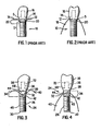
- FIGS. 1 and 2 show prior art implant 10, abutment-implant interface 12, abutment 14 and crown 16 constructed according to the current state of the art.
- Implant 10 according to the current state of the art, has a bone apposition surface 17, typically threads or otherwise roughened surface, extending into alveolar bone 18.
- Abutment-implant interface 12 extends partially into the alveolar bone and has polished surface 20, which is not suitable for bone apposition.
- Use of implant 10, constructed according to the current state of the art results in bone-tissue resorption in bone-tissue/soft-tissue transition region 22 because polished surface 20 contacts bone-tissue, which as discussed, leads to bone resorption. Any loss of natural bone structure or topography is highly undesirable from both structural and aesthetic perspectives. Even the smallest bone-tissue loss between the tooth and an implant will lead to soft-tissue shrinkage due to lack of boney support, resulting in "black triangles" (open spaces) between the teeth-a highly unaesthetic situation.
- FIGS. 3 and 4 show a two-stage implant according to an embodiment of the present invention.
- Implant 24 has shaft 26, substantially planar abutment-implant interface 28, distal end 30, proximal end 32 and bone-tissue/soft-tissue transition region 34. Abutment 36 and crown 38 are attached to implant 24 using means well known to the skilled artisan for two-stage implants.
- Implant 24 is made from a biocompatible material, including but not limited to, metal, ceramic, glasses or any combination thereof.
- Preferably implant 24 is made from titanium or an alloy thereof.
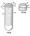
- Bone-tissue/soft-tissue transition region 34 has a scalloped bone-tissue apposition surface 42, which approximately follows the naturally occurring contours of existing bone 40, and a scalloped soft-tissue apposition surface 44, which approximately follows the naturally occurring contours of the existing soft-tissue (not shown).
- a scalloped tissue-attachment surface 42 to maintain the naturally occurring bone-tissue morphology
- soft-tissue apposition surface 44 to maintain the naturally occurring soft-tissue morphology.
- the degree of scalloping or the height of the convex and concave regions depends on, inter alia, the degree of existing bone-tissue resorption, the size of the implant, the implant location within the arch, the bone morphology and the soft-tissue morphology.
- the dimensions are similar to the scalloped appearance of the cemento-enamel (CE) junction observed on natural teeth.
- the vertical difference between the highest and lowest point of the scalloped margin ranges from less than 1mm on posterior teeth to approximately 3-5 mm on anterior teeth.
- bone-tissue apposition surface 42 is obtained by machining, application of textured surfaces, acid etching, blasting with particles, applying growth factor, applying protein.
- soft-tissue apposition surface 44 can be achieved by polishing or other treatment that leaves a surface to promote, enhance, and/or maintain soft-tissue growth and/or apposition.
- shaft 26 has threads 45, or other means well known in the art, to anchor the implant into the alveolar bone.
- the surgeon inserts distal end 30 into the alveolar bone such that bone-tissue apposition surface 42 and soft-tissue apposition surface 44 approximately mirror the existing bone- and soft-tissue morphology respectively.
- the implant should be aligned such that the highest points of bone apposition surface 42 are substantially aligned with the interproximal areas of the bone-tissue and such that the lowest points are substantially aligned with the buccal and lingual area of the bone-tissue.
- the surgeon sutures tissue over the implant, waits several months for the bone to adhere to the implant, opens the tissue, attaches abutment 36 to abutment-implant interface 28 and attaches crown 38 to abutment 36.
- Bone-tissue apposition surface 42 and soft-tissue apposition surface 44 maintain bone- and soft-tissue attachment levels and facilitate prevention of peri-implant infections, which occur due to increased peri-implant pocket depths frequently observed with the prior art implant designs. Therefore, implants constructed according to the present invention increase the longevity of the implant and improve the aesthetic appearance of the restoration.
- abutment-implant interface 28 has substantially planar upper surface 25, which is approximately 90° to the longitudinal axis of shaft 26, and connecting means 46 for connecting abutment 36 ( FIGS. 3 and 4 ) to abutment-implant interface 28.
- Connecting means 46 is well known in the art and includes, but is not limited to, internal hex, external hex, standard hex, tall hex, wide hex or camlog.
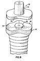
- abutment-implant interface 48 has at least its edges contoured to approximate the contours of the alveolar bone, thereby defining a contoured upper surface 50 ( FIG. 8 ) surrounding connecting means 46.
- abutment 52 which has lower contoured surface 54 configured to substantially mate with contoured upper surface 50.
- the upper and lower contoured surfaces provide additional lateral support between abutment 52 and abutment-implant interface 48.
- contoured upper surface 48 of this alternative embodiment results in a narrower depth between gum line 54 and abutment-implant interface 48 ( FIGS. 6 and 7 ), thus enhancing longevity of the restoration as a result of decreased pocket depths.
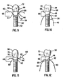
- FIGS. 9 and 10 show one-stage implant 58, according to another example.
- Implant 58 includes shaft 60, distal end 62, proximal end 64 and bone-tissue/soft-tissue transition region 66 with scalloped bone-tissue apposition surface 42 and scalloped soft-tissue apposition surface 44, as substantially described above.
- Abutment 69 is permanently attached to the one-stage implant 58 as is well know in the art.
- One-or two-stage implants may include either a planar abutment-crown interface 68 ( FIGS. 3, 4 , 9 and 10 ) or a contoured abutment-crown interface 70 ( FIGS. 6, 7 , 11 and 12 ), the latter of which substantially matches the natural contour of the alveolar bone.
- Contoured abutment-crown interface 70 allows for crown 38, in both one-and two-stage implants, to extend further towards the gum line, thereby resulting in a more aesthetically pleasing restoration.
- Chimney 72 or other means well known to the skilled artisan, is provided in both one-and two-stage implants according to the present invention for attaching crown 38 to the abutment.
Abstract
Description
- The present invention relates generally to the field of implant dentistry, and more particularly to the design of one- and two-stage endosseous implants.
- Endosseous, i.e., intra boney, implants like that disclosed in
EP0868889 are commonly used to support fixed or removable prostheses where a patient's natural roots have been lost, and as a consequence, support is lacking to provide an adequate foundation onto which the dentist can rebuild a dentition. As the aging population retains more of their natural teeth, and as the younger generations want to take advantage of more conservative approaches offered by implant dentistry, e.g., using a single implant rather than cutting down adjacent teeth to support a short span bridge to replace a missing tooth, implant dentistry has gained more and more popularity and has moved into the mainstream of dentists worldwide. - The current implant design is based on an endosseous fixture, a titanium screw that acts as an artificial root. Brånemark, Tissue-Integrated Prostheses (1985). Modifications made to the endosseous fixture have centered on the macro structure of the implant (e.g., by exchanging the screw with a press-fit/cylindrical implant, a stepped screw or cylinder, or a tapered screw or cylinder), (Brunski J.B., Biomechanics Of Oral Implant,. Future Research Directions NIH Consensus Development Conference on Dental Implants, 1988; Kirsch A. et al., The IMZ Osseointegrated Implant System, Dent. Clin. North Am. 1989 (4), 33:733-791; Niznick G.A., A Multimodal Approach To Implant Prosthodontics, Dent. Clin. North Am. 1989 (4), 33:869-878; Wennerberg A. et al., Design And Surface Characteristics Of 13 Commercially Available Oral Implant Systems, Id 1993:8:622-633; Siegele D. et al., Numerical Investigations Of The Influence Of Implant Shape On Stress Distribution In The Jaw Bone, Id, 1989:4:333-340; Olsson M. et al., MkII-a Modified Self-Tapping Brånemark Implant: 3-Year Results, Id at 1995:10:15-21; Langer B. et al., The Wide Fixture: A Solution For Special Bone Situations And A Rescue For The Compromised Implant, Part 1, Id, 1993:8:400-408; Schnitman P.A. et al., Implants For Partial Edentulism, NIH Consensus Development Conference On Dental Implants, 1988), on the micro structure (e.g., surface modifications such as use of machined titanium, blasted titanium, titanium alloy, acid-etched titanium, plasma-sprayed titanium and hydroxyappatite coating such as growth factors and proteins), (Baier R.E. et al., Future Directions In Surface Preparation Of Dental Implants, NIH Consensus Development Conference On Dental Implants, 1988; Young F.A., Future Directions In Dental Implant Materials Research, Id; Krauser J., Hydroxylappatite-Coated Dental Implants, Dent. Clin. North Am. 1989, 33:4:879-903; Buser D. et al., Tissue Integration Of One-Stage ITl Implants: 3-Year Results Of A Longitudinal Study With Hollow-Cylinder And Hollow-Screw Implants, Int. J. Oral Maxillofac. Implants, 1991:6:405-412), on one-vs-two-stage designs, (Weber H.P. et al., Comparison Of Healed Tissues Adjacent To Submerged And Non-Submerged Unloaded Titanium Dental Implants, Clin. Oral Impl. Res. 1996:7:11-19; Busser D. et al., Tissue Integration Of One-Stage ITI Implants: 3-Year Results Of A Longitudinal Study With Hollow-Cylinder and Hollow-Screw Implants, Int. J. Oral Maxillofac Implants 1991:6:405-412), and on modifying the connection between the implant and its abutment (e.g., either internal hex, external hex, standard hex, tall hex, wide hex, etc.), (
U.S. Pat. No. 4,960,381 ;U.S. Pat. No. 5,407,359 ;U.S. Pat. No. 5,209,666 ;U.S. Pat. No. 5,110,292 ). - Irrespective of the design variables discussed above, current systems have two general characteristics in common: First, the abutment-implant interface is planar; and second, the area intended for bone apposition, i.e., osseointegration, terminates parallel to the abutment-implant interface, 360 degrees around the implant.
- Traditionally, endosseous implants were designed for treatment of the fully edentulous patient. In general, this particular patient population exhibits reduced bone-tissue volume, both in height and width when compared to the partially edentulous patient with recent or impending tooth loss. However, the bone-tissue morphology of partially edentulous patients significantly differs from that of fully edentulous patients, in that the naturally occurring supporting bone structures reveal a scalloped architecture around the tooth.
- Currently available implant technology does not take the different bone-tissue morphologies into consideration. Heretofore use of an implant with an intended bone-tissue apposition surface parallel to a flat abutment-implant interface has led to either (1) placement of soft-tissue intended parts of the implant within bone-tissue, leading to bone-tissue resorption in these areas, and/or (2) exposure of hard-tissue intended surfaces to the soft tissue, resulting in possible peri-implant infections due to bacterial colonization around the rough surface and potential loss of the implant.
- Various aspects of the invention are defined in the independent claim. Some preferred features are defined in the dependent claims.
- The present invention is directed towards novel endosseous implants, which are structured to better maintain hard and soft-tissue in the area where the implant exits from the bone-tissue and transverses the soft-tissue. More particularly, the implants of the present invention are designed so that areas intended for hard- and soft-tissue apposition exhibit a scalloped appearance, including convex and concave patterns, which approximate the naturally occurring bone morphology. Thus, the implants of the present invention provide substantially increased attachment possibilities for both bone-tissue and soft-tissue, thereby facilitating bone-tissue and soft-tissue preservation and maintenance.
- The present invention will enable the surgeon to place an implant into residual bone with the surface of the implant intended for bone-tissue contact and apposition being substantially in contact with bone-tissue, and with the surface intended for soft-tissue apposition (polished/treated with soft-tissue specific surface modifications) being substantially in contact with soft-tissue.
- More specifically, the implant, according to an embodiment of the present invention, is a substantially cylindrical shaft made from a biocompatible material having a distal end and a proximal end. A bone-tissue/soft-tissue transition region and an abutment-implant interface are both disposed towards the proximal end of the shaft. The bone-tissue/soft-tissue transition region is defined as the approximate region of the shaft and/or the abutment-implant interface where the implant exits the bone-tissue and transverses into the soft-tissue. The bone-tissue/soft-tissue transition region has a bone-tissue apposition surface configured to approximate the physiological contours of the alveolar bone. In a two-stage implant, the abutment-implant interface may be either substantially planar, approximately 90° to the longitudinal axis of the shaft, or contoured to approximate the contour of the alveolar bone. In a one-stage implant the abutment is permanently attached to the abutment-implant interface, or an integral part of the implant itself. The abutment, in both one-and two-stage implants, has an abutment-crown interface, which is either substantially planar or contoured to approximate the contour of the alveolar bone, and a chimney onto which the crown is secured.
- An implant constructed according to the principles of the present invention facilitates hard- and soft-tissue maintenance, increases longevity of the implant and improves its aesthetic appearance. As will be readily apparent to the skilled artisan, the present invention may be applied to numerous prosthetic applications, such as, but not limited to, a single tooth replacement, an abutment for a bridge (fixed partial denture) regardless of the nature of the other abutment (natural tooth or implant), a pier abutment or an over denture abutment.
-
-
FIG. 1 depicts a frontal view of a prior art implant; -
FIG. 2 depicts an interproximal view of the prior art implant inFIG. 1 ; -
FIG. 3 depicts a frontal view an implant according to an embodiment of the present invention; -
FIG. 4 depicts an interproximal view of the implant inFIG. 3 ; -
FIG. 5A depicts a three-dimensional top frontal view of the implant inFIG. 3 ; -
FIG. 5B depicts a three-dimensional interproximal top view of the implant inFIG. 3 -
FIG. 6 depicts a frontal view of an implant according to another embodiment of the present invention; -
FIG. 7 depicts an interproximal view of the implant inFIG. 6 ; -
FIG. 8 depicts a three-dimensional top view of the implant inFIG. 6 ; -
FIG. 9 shows a frontal view of an implant according to another example; -
FIG. 10 depicts an interproximal view of the implant inFIG. 9 ; -
FIG. 11 depicts a frontal view of an implant according to another example; and -
FIG. 12 depicts an interproximal view of the implant inFIG. 11 . -
FIGS. 1 and 2 showprior art implant 10, abutment-implant interface 12,abutment 14 andcrown 16 constructed according to the current state of the art.Implant 10, according to the current state of the art, has abone apposition surface 17, typically threads or otherwise roughened surface, extending intoalveolar bone 18. Abutment-implant interface 12 extends partially into the alveolar bone and has polishedsurface 20, which is not suitable for bone apposition. Use ofimplant 10, constructed according to the current state of the art, results in bone-tissue resorption in bone-tissue/soft-tissue transition region 22 becausepolished surface 20 contacts bone-tissue, which as discussed, leads to bone resorption. Any loss of natural bone structure or topography is highly undesirable from both structural and aesthetic perspectives. Even the smallest bone-tissue loss between the tooth and an implant will lead to soft-tissue shrinkage due to lack of boney support, resulting in "black triangles" (open spaces) between the teeth-a highly unaesthetic situation. -
FIGS. 3 and 4 show a two-stage implant according to an embodiment of the present invention.Implant 24 hasshaft 26, substantially planar abutment-implant interface 28,distal end 30,proximal end 32 and bone-tissue/soft-tissue transition region 34.Abutment 36 andcrown 38 are attached to implant 24 using means well known to the skilled artisan for two-stage implants.Implant 24 is made from a biocompatible material, including but not limited to, metal, ceramic, glasses or any combination thereof. Preferablyimplant 24 is made from titanium or an alloy thereof. - Bone-tissue/soft-
tissue transition region 34 has a scalloped bone-tissue apposition surface 42, which approximately follows the naturally occurring contours of existingbone 40, and a scalloped soft-tissue apposition surface 44, which approximately follows the naturally occurring contours of the existing soft-tissue (not shown). Thus, there are two distinctive scalloped tissue-attachment surfaces: bone-tissue apposition surface 42 to maintain the naturally occurring bone-tissue morphology; and soft-tissue apposition surface 44 to maintain the naturally occurring soft-tissue morphology. The degree of scalloping or the height of the convex and concave regions depends on, inter alia, the degree of existing bone-tissue resorption, the size of the implant, the implant location within the arch, the bone morphology and the soft-tissue morphology. The dimensions are similar to the scalloped appearance of the cemento-enamel (CE) junction observed on natural teeth. The vertical difference between the highest and lowest point of the scalloped margin ranges from less than 1mm on posterior teeth to approximately 3-5 mm on anterior teeth. By way of example, bone-tissue apposition surface 42 is obtained by machining, application of textured surfaces, acid etching, blasting with particles, applying growth factor, applying protein. Also by way of example, soft-tissue apposition surface 44 can be achieved by polishing or other treatment that leaves a surface to promote, enhance, and/or maintain soft-tissue growth and/or apposition. Below the bone-tissue/soft-tissue transition region 34,shaft 26 hasthreads 45, or other means well known in the art, to anchor the implant into the alveolar bone. - In use, the surgeon inserts
distal end 30 into the alveolar bone such that bone-tissue apposition surface 42 and soft-tissue apposition surface 44 approximately mirror the existing bone- and soft-tissue morphology respectively. The implant should be aligned such that the highest points ofbone apposition surface 42 are substantially aligned with the interproximal areas of the bone-tissue and such that the lowest points are substantially aligned with the buccal and lingual area of the bone-tissue. In a two-stage process, the surgeon sutures tissue over the implant, waits several months for the bone to adhere to the implant, opens the tissue, attachesabutment 36 to abutment-implant interface 28 and attachescrown 38 toabutment 36. Bone-tissue apposition surface 42 and soft-tissue apposition surface 44 maintain bone- and soft-tissue attachment levels and facilitate prevention of peri-implant infections, which occur due to increased peri-implant pocket depths frequently observed with the prior art implant designs. Therefore, implants constructed according to the present invention increase the longevity of the implant and improve the aesthetic appearance of the restoration. - Referring to
FIGS. 5A and 5B , abutment-implant interface 28 has substantially planarupper surface 25, which is approximately 90° to the longitudinal axis ofshaft 26, and connectingmeans 46 for connecting abutment 36 (FIGS. 3 and 4 ) to abutment-implant interface 28. Connecting means 46 is well known in the art and includes, but is not limited to, internal hex, external hex, standard hex, tall hex, wide hex or camlog. In an alternative embodiment of the present invention, as shown inFIGS. 6-8 , abutment-implant interface 48 has at least its edges contoured to approximate the contours of the alveolar bone, thereby defining a contoured upper surface 50 (FIG. 8 ) surrounding connectingmeans 46. Also provided in this alternative embodiment isabutment 52, which has lower contouredsurface 54 configured to substantially mate with contouredupper surface 50. The upper and lower contoured surfaces provide additional lateral support betweenabutment 52 and abutment-implant interface 48. Additionally, contouredupper surface 48 of this alternative embodiment results in a narrower depth betweengum line 54 and abutment-implant interface 48 (FIGS. 6 and 7 ), thus enhancing longevity of the restoration as a result of decreased pocket depths. - A skilled artisan will readily recognize that the principles of the present invention can be equally applied to one-stage as well as two-stage processes. For example,
FIGS. 9 and 10 show one-stage implant 58, according to another example.Implant 58 includesshaft 60,distal end 62,proximal end 64 and bone-tissue/soft-tissue transition region 66 with scalloped bone-tissue apposition surface 42 and scalloped soft-tissue apposition surface 44, as substantially described above.Abutment 69 is permanently attached to the one-stage implant 58 as is well know in the art. - One-or two-stage implants, according to alternative embodiments of the present invention, may include either a planar abutment-crown interface 68 (
FIGS. 3, 4 ,9 and 10 ) or a contoured abutment-crown interface 70 (FIGS. 6, 7 ,11 and 12 ), the latter of which substantially matches the natural contour of the alveolar bone. Contoured abutment-crown interface 70 allows forcrown 38, in both one-and two-stage implants, to extend further towards the gum line, thereby resulting in a more aesthetically pleasing restoration.Chimney 72, or other means well known to the skilled artisan, is provided in both one-and two-stage implants according to the present invention for attachingcrown 38 to the abutment.
Claims (20)
- An endosseous dental implant (24), comprising:a shaft (26) from a biocompatible material, said shaft (26) having a distal end (30) and a proximal end (32);an abutment-implant interface (28, 48) disposed towards the proximal end (32) of said shaft (26);a bone-tissue apposition surface (42) formed on said shaft (26) and disposed adjacent to said abutment-implant interface (28, 48), said bone-tissue apposition surface (42) having a scalloped appearance and being configured to approximate the physiological contours of naturally occurring bone-tissue morphology, wherein the shaft comprises threads (45) below a bone-tissue/soft-tissue transition region, characterized in that
said bone-tissue apposition surface (42) is obtained by machining, acid etching, application of textured surfaces, applying growth factor, applying protein, or blasting with particles, and a soft-tissue apposition surface (44) formed on said shaft (26) and disposed between said bone-tissue apposition surface (42) and said abutment-implant interface (28,48),
whereinthe bone-tissue apposition surface (42) and the soft-tissue apposition surface (44) exhibit a scalloped appearance, including convex and concave patterns, which approximate the naturally occurring bone morphology. - An endosseous dental implant (24) according to claim 1, wherein the soft-tissue apposition surface (44) is a polished surface.
- The endosseous dental implant (24) according to claim 1 further comprising: a means for connecting (46) an abutment (36, 52) to said abutment-implant interface (28, 48) for use in a two-stage procedure.
- The endosseous dental implant (24) according to claim 3, wherein said abutment-implant interface (28) has a substantially planar upper surface (25) substantially 90 degrees to the longitudinal axis of said shaft (26), and wherein said planar upper surface (25) substantially surrounds said means for connecting (46).
- The endosseous dental implant (24) according to claim 3, wherein said abutment-implant interface (48) has a contoured upper surface (50), and wherein said contoured upper surface (50) substantially surrounds said means for connecting (46).
- The endosseous dental implant (24) according to claim 5, further comprising an abutment (52) wherein a lower surface (54) of the abutment (52) substantially abuts against said contoured upper surface (50), thereby providing improved lateral support.
- The endosseous dental implant (24) according to claim 1, further comprising:an abutment (36, 52) permanently attached to said abutment-implant interface (28, 48) for use in a one-stage procedure;wherein said shaft (26) and said abutment (36, 52) are constructed from a single piece of material.
- The endosseous dental implant (24) according to claim 7, wherein said abutment (36) has a substantially planar upper surface (25) substantially 90 degrees to the longitudinal axis of said shaft (26) and wherein said planar upper surface (25) substantially surrounds a chimney (72).
- The endosseous dental implant (24) according to claim 7, wherein said abutment has a contoured upper surface and wherein said contoured upper surface substantially surrounds a chimney (72).
- The endosseous dental implant (24) according to claim 1, wherein the implant (24) is a two-stage implant, the implant (24) further comprising:an abutment (36, 52) configured to attach to said abutment-implant interface (28, 48);a means for connecting (46) said abutment (36, 52) to said abutment-implant interface (28, 48); anda crown (38) having a distal end configured to fit over said abutment (36, 52).
- The endosseous dental implant (24) according to claim 10, wherein said abutment-implant interface (28) has a substantially planar upper surface (25) substantially surrounding said means for connecting (46), and wherein said upper planar surface (25) is substantially 90 degrees to the longitudinal axis of said shaft (26).
- The endosseous dental implant (24) according to claim 11, wherein said abutment (36) has a substantially planar upper abutment-crown interface (68).
- The endosseous dental implant (24) according to claim 11, wherein said abutment (28) has a contoured upper abutment-crown interface surface (70) substantially surrounding a chimney (72), and wherein a distal end of said crown (38) is configured such that at least an outside surface of said crown extends to and follows the contours of said upper abutment-crown interface surface (70), thereby providing a narrow depth between the distal end of said crown (38) and said bone-tissue apposition surface (42).
- The endosseous dental implant (24) according to claim 10, wherein said abutment-implant interface (48) has a contoured upper surface (50) substantially surrounding said means for connecting (46), and said contoured upper surface (50) approximately matches the contour of the natural bone morphology, and wherein said abutment (52) has a lower surface (54) configured to substantially abut said contoured upper surface (50).
- The endosseous dental implant (24) according to claim 14, wherein said abutment (52) has a substantially planar upper abutment-crown interface surface (68).
- The endosseous dental implant (24) according to claim 14, wherein said abutment (52) has a contoured upper abutment-crown (38) interface surface (70) substantially surrounding a chimney (72), and wherein a distal end of said crown (38) is configured such that at least an outside surface of said crown (38) extends to and follows the contours of said upper abutment-crown interface surface (70), thereby providing a narrow depth between the distal end of said crown (38) and said bone-tissue apposition surface (42).
- The endosseous dental implant system (24) according to claim 1, further comprising:an abutment (36, 52) permanently attached to the proximal end (32) of said shaft (26), wherein said shaft (26) and said abutment (36, 52) are constructed from a single piece of material; anda crown (38) having a distal end configured to secure to said abutment (36, 52).
- The endosseous dental implant (24) according to claim 17, wherein said abutment (36, 52) has a substantially planar upper surface (68) substantially surrounding a chimney (72), and wherein said upper planar surface (68) is substantially 90 degrees to the longitudinal axis of said shaft.
- The endosseous dental implant (24) according to claim 17; wherein said abutment (36, 52) has a contoured upper surface (70) substantially surround a chimney (72), and wherein said contoured upper surface (70) approximately matches the contour of naturally occurring bone-tissue morphology.
- The endosseous dental implant (24) according to claim 19, wherein a distal end of said crown (38) is configured such that at least an outside surface of said crown (38) extends to and follows the contours of said contoured upper surface (70), thereby providing a narrow depth between the distal end of said crown (38) and the bone-tissue apposition surface (42).
Priority Applications (1)
| Application Number | Priority Date | Filing Date | Title |
|---|---|---|---|
| EP10010488A EP2311403A1 (en) | 1998-12-01 | 1999-12-01 | Bioroot endosseous implant |
Applications Claiming Priority (3)
| Application Number | Priority Date | Filing Date | Title |
|---|---|---|---|
| US203822 | 1998-12-01 | ||
| US09/203,822 US6174167B1 (en) | 1998-12-01 | 1998-12-01 | Bioroot endosseous implant |
| PCT/US1999/028304 WO2000032134A1 (en) | 1998-12-01 | 1999-12-01 | Bioroot endosseous implant |
Related Child Applications (2)
| Application Number | Title | Priority Date | Filing Date |
|---|---|---|---|
| EP10010488A Division-Into EP2311403A1 (en) | 1998-12-01 | 1999-12-01 | Bioroot endosseous implant |
| EP10010488.4 Division-Into | 2010-09-24 |
Publications (4)
| Publication Number | Publication Date |
|---|---|
| EP1135080A1 EP1135080A1 (en) | 2001-09-26 |
| EP1135080A4 EP1135080A4 (en) | 2005-05-18 |
| EP1135080B1 EP1135080B1 (en) | 2011-08-24 |
| EP1135080B2 true EP1135080B2 (en) | 2014-12-17 |
Family
ID=22755469
Family Applications (2)
| Application Number | Title | Priority Date | Filing Date |
|---|---|---|---|
| EP99968057.2A Expired - Lifetime EP1135080B2 (en) | 1998-12-01 | 1999-12-01 | Bioroot endosseous implant |
| EP10010488A Withdrawn EP2311403A1 (en) | 1998-12-01 | 1999-12-01 | Bioroot endosseous implant |
Family Applications After (1)
| Application Number | Title | Priority Date | Filing Date |
|---|---|---|---|
| EP10010488A Withdrawn EP2311403A1 (en) | 1998-12-01 | 1999-12-01 | Bioroot endosseous implant |
Country Status (9)
| Country | Link |
|---|---|
| US (3) | US6174167B1 (en) |
| EP (2) | EP1135080B2 (en) |
| JP (1) | JP4279991B2 (en) |
| AT (1) | ATE521298T1 (en) |
| AU (1) | AU753575B2 (en) |
| BR (1) | BR9915830A (en) |
| CA (1) | CA2352809C (en) |
| ES (1) | ES2372157T5 (en) |
| WO (1) | WO2000032134A1 (en) |
Families Citing this family (95)
| Publication number | Priority date | Publication date | Assignee | Title |
|---|---|---|---|---|
| US6419491B1 (en) * | 1993-11-02 | 2002-07-16 | Bio-Lok International, Inc. | Dental implant system with repeating microgeometric surface patterns |
| US6454569B1 (en) * | 1993-11-02 | 2002-09-24 | Biolok International, Inc. | Dental implant having a dual bio-affinity collar |
| US6174167B1 (en) | 1998-12-01 | 2001-01-16 | Woehrle Peter S. | Bioroot endosseous implant |
| DE50114754D1 (en) * | 2000-01-04 | 2009-04-23 | Straumann Holding Ag | ENOSSAL DENTAL IMPLANT |
| US6854972B1 (en) | 2000-01-11 | 2005-02-15 | Nicholas Elian | Dental implants and dental implant/prosthetic tooth systems |
| US6431867B1 (en) | 2000-04-18 | 2002-08-13 | Glenn Gittelson | Dental implant system |
| US20030031981A1 (en) * | 2000-10-21 | 2003-02-13 | Robert Holt | Prosthetic implant |
| US20050177237A1 (en) * | 2001-04-12 | 2005-08-11 | Ben Shappley | Spinal cage insert, filler piece and method of manufacturing |
| WO2002083194A1 (en) * | 2001-04-12 | 2002-10-24 | Therics, Inc. | Method and apparatus for engineered regenerative biostructures |
| US6527554B2 (en) * | 2001-06-04 | 2003-03-04 | Nobel Biocare Ab | Natural implant system |
| US20060199152A1 (en) * | 2001-06-04 | 2006-09-07 | Hurson Steven M | Natural implant system |
| CA2353051A1 (en) * | 2001-07-12 | 2003-01-12 | Innova Corp. | Implant for use in aesthetic regions of the mouth |
| US7264469B2 (en) * | 2001-08-10 | 2007-09-04 | Juan Carlos Abarno | Split-implant and abutment system for dental reconstruction |
| US6537069B1 (en) * | 2001-10-01 | 2003-03-25 | Earl Wayne Simmons, Jr. | Method and apparatus for dental implants |
| US20030068599A1 (en) * | 2001-10-04 | 2003-04-10 | Balfour Alan R. | Esthetic profile endosseous root-formed dental implant |
| US20030087217A1 (en) * | 2001-11-07 | 2003-05-08 | Coatoam Gary W. | Dental implant method & apparatus |
| DE10159683A1 (en) * | 2001-11-30 | 2003-06-18 | Michael Gahlert | Dantalimplantat |
| EP1460960B1 (en) * | 2001-12-03 | 2010-01-20 | Astra Tech AB | Modified dental implant fixture |
| US6655961B2 (en) | 2001-12-03 | 2003-12-02 | Richard Day Cottrell | Modified dental implant fixture |
| US20040038179A1 (en) | 2001-12-07 | 2004-02-26 | Ajay Kumar | Healing abutment |
| SE520756C2 (en) * | 2001-12-21 | 2003-08-19 | Nobel Biocare Ab | Method of providing surface structure on implants as well as such implants |
| SE523395C2 (en) * | 2001-12-21 | 2004-04-13 | Nobel Biocare Ab | Implants and methods and systems for providing such implants |
| JP4280638B2 (en) * | 2002-01-11 | 2009-06-17 | ノベル バイオケア サーヴィシィズ アクチエンゲゼルシャフト | Dental implant device |
| BR0215756A (en) * | 2002-06-06 | 2005-03-01 | Nobel Biocare Ab | Dental Implants and Methods of Dental Implantation, Increasing Tissue Bonding Between a Dental Prosthesis and Patient Tissue and Dental Implant Manufacturing |
| US20030232308A1 (en) * | 2002-06-14 | 2003-12-18 | Simmons Earl Wayne | Method and apparatus for dental implants |
| US7291013B2 (en) * | 2002-06-28 | 2007-11-06 | Zimmer Dental, Inc. | Organic shaped interface for dental implant devices |
| US7341453B2 (en) * | 2002-11-01 | 2008-03-11 | Coatoam Gary W | Dental implant method and apparatus |
| JP4531569B2 (en) * | 2003-01-03 | 2010-08-25 | ノベル バイオケア サーヴィシィズ アクチエンゲゼルシャフト | Dental implant system |
| US20040185418A1 (en) * | 2003-03-18 | 2004-09-23 | Schulter Carl W. | Dental implant fixture |
| EP1626671A2 (en) * | 2003-05-16 | 2006-02-22 | Nobel Biocare Services AG | Dental implant system |
| US20050214714A1 (en) * | 2003-05-16 | 2005-09-29 | Wohrle Peter S | Dental implant system |
| IL156033A0 (en) | 2003-05-21 | 2004-03-28 | Ophir Fromovich Ophir Fromovic | Dental implant |
| DE10331524A1 (en) * | 2003-07-11 | 2005-02-03 | Gerhard Dr. Bruckner | Dental implant |
| ITMI20031720A1 (en) | 2003-09-08 | 2005-03-09 | Carlo Tinti | AESTHETIC ENDOSSEO PLANT. |
| US7110650B2 (en) * | 2003-09-12 | 2006-09-19 | The Board Of Trustees Of The Leland Stanford Junior University | Method for configuring air-core photonic-bandgap fibers free of surface modes |
| US20060194171A1 (en) * | 2003-10-03 | 2006-08-31 | Sargon Lazarof | Bi-polar implant |
| US20050085922A1 (en) * | 2003-10-17 | 2005-04-21 | Shappley Ben R. | Shaped filler for implantation into a bone void and methods of manufacture and use thereof |
| ATE404228T1 (en) * | 2003-10-27 | 2008-08-15 | Straumann Holding Ag | IMPLANT WITH A CERAMIC COATING |
| GB0327822D0 (en) * | 2003-12-01 | 2003-12-31 | Materialise Nv | Method for manufacturing a prosthesis made prior to implant placement |
| SE526749C2 (en) | 2003-12-11 | 2005-11-01 | Nobel Biocare Ab | Dental implant device and method for its preparation |
| SE526746C2 (en) * | 2003-12-11 | 2005-11-01 | Nobel Biocare Ab | Implant applicable to dentures with associated soft tissue |
| SE526747C2 (en) * | 2003-12-22 | 2005-11-01 | Nobel Biocare Ab | Implant applicable in an installation position in a hollow hole in the jawbone |
| DE602004010613T3 (en) * | 2004-03-25 | 2013-12-24 | Straumann Holding Ag | Improved endosseous dental implant |
| US20050244789A1 (en) * | 2004-04-30 | 2005-11-03 | Crohin Constant C | Aesthetic dental implant fixture and abutment system |
| EP1756634B1 (en) * | 2004-05-08 | 2013-07-10 | The Board Of Trustees Of The Leland Stanford Junior University | Photonic-bandgap fiber with hollow core |
| US20080014556A1 (en) * | 2004-06-04 | 2008-01-17 | Stefan Neumeyer | Tooth Implant |
| US20070264612A1 (en) * | 2004-11-23 | 2007-11-15 | Mount K T | Dental implant and method for making and installing same |
| US20060154203A1 (en) * | 2005-01-10 | 2006-07-13 | Emanuelli Silvio F | Dental implants having anatomical emergence |
| DE102005008273A1 (en) | 2005-02-22 | 2006-08-24 | Mundorf, Sönke, Dr. | Tooth implant comprises a bone anchoring part having an outer surface for anchoring in the jawbone and formed as a tissue anchoring part and a tooth alignment part fixed to the bone anchoring part on which a crown is fixed |
| WO2006096720A1 (en) * | 2005-03-07 | 2006-09-14 | University Of Maryland, Baltimore | Dental implant screw and method of use |
| US8506296B2 (en) | 2005-06-17 | 2013-08-13 | Zimmer Dental, Inc. | Dental restorative system and components |
| US8007279B2 (en) * | 2005-06-17 | 2011-08-30 | Zimmer Dental, Inc. | Dental restorative system and components |
| US8430668B2 (en) * | 2005-06-17 | 2013-04-30 | Zimmer Dental, Inc. | Dental restorative system and components |
| US20070031793A1 (en) * | 2005-08-03 | 2007-02-08 | Kelley Casement | Provisional crown for dental implants |
| US20070031792A1 (en) * | 2005-08-03 | 2007-02-08 | Kelley Casement | Provisional crown for dental implants |
| EP1792580A1 (en) | 2005-09-27 | 2007-06-06 | Ziterion GmbH | Two-part dental implants made of biocompatible ceramics |
| US20070099152A1 (en) * | 2005-10-31 | 2007-05-03 | Albert Busch | Dental implant system |
| JP2008149121A (en) * | 2006-11-24 | 2008-07-03 | Eiji Kato | Dental implant |
| EP1967157A1 (en) | 2007-03-05 | 2008-09-10 | Ziterion GmbH | Hybrid two-part dental implant |
| BRPI0809733B8 (en) * | 2007-04-17 | 2021-06-22 | Indi Implant Systems Ug | dental implant system |
| EP1982671B1 (en) | 2007-04-19 | 2016-03-09 | Straumann Holding AG | Dental implant having a surface made of a ceramic material |
| WO2009020446A1 (en) * | 2007-08-06 | 2009-02-12 | Mount K Tim | Dental implant and method for making and installing same |
| US8066511B2 (en) * | 2008-03-18 | 2011-11-29 | Woehrle Peter | Asymmetrical dental implant |
| EP2106767A1 (en) | 2008-03-31 | 2009-10-07 | Ziterion GmbH | Two-part dental implant |
| EP2145600A1 (en) * | 2008-07-14 | 2010-01-20 | Nobel Biocare Services AG | Improved fixture of two-piece dental implants |
| US8616881B2 (en) * | 2009-06-30 | 2013-12-31 | Dental Design Consultants, Llc | Modified asymmetrical dental implant |
| US9433480B2 (en) * | 2010-12-21 | 2016-09-06 | Zimmer Dental, Inc. | Implant with porous sleeve including anti-rotation features |
| JP5108117B2 (en) * | 2011-01-04 | 2012-12-26 | ノベル バイオケア サーヴィシィズ アクチエンゲゼルシャフト | Natural implant system |
| US20120288826A1 (en) * | 2011-05-11 | 2012-11-15 | Fitton Iii Russell P | Dental Implants and Methods for Their Insertion into Patients |
| US8992222B2 (en) | 2012-05-02 | 2015-03-31 | Richard D. Cottrell | Ridge lap dental implant |
| TWI487507B (en) * | 2012-05-07 | 2015-06-11 | Univ Nat Cheng Kung | Dental implant with cushion |
| US9168110B2 (en) | 2012-05-29 | 2015-10-27 | Biomet 3I, Llc | Dental implant system having enhanced soft-tissue growth features |
| US9877809B2 (en) | 2012-07-23 | 2018-01-30 | Olista Ag | Abutment system for immediate implants for producing a dental prosthesis |
| TWI583359B (en) | 2013-02-22 | 2017-05-21 | 巴科納 包瑞斯 Ds | Endosseous dental implant and abutment for prevention of bone loss |
| USD733886S1 (en) | 2013-11-01 | 2015-07-07 | Provisional Implant Technology, Llc | Provisional dental implant |
| USD734465S1 (en) | 2013-11-01 | 2015-07-14 | Provisional Implant Technology Llc | Provisional dental implant |
| US20160324602A1 (en) * | 2013-12-30 | 2016-11-10 | Olista Ag | Abutment system for immediate implants |
| US20160015483A1 (en) * | 2014-04-30 | 2016-01-21 | Osseodyne Surgical Solutions, LLC. | Osseointegrative surgical implant |
| US10292792B2 (en) | 2014-08-29 | 2019-05-21 | Nobel Biocare Services Ag | Restoration dental implant and method |
| BR102014031426B1 (en) | 2014-12-15 | 2018-07-24 | Jjgc Ind E Comercio De Materiais Dentarios S/A | implant |
| USD816841S1 (en) | 2014-12-15 | 2018-05-01 | Jjgc Industria E Comercio De Materiais Dentarios S/A | Bone implant |
| EP3034033A1 (en) | 2014-12-16 | 2016-06-22 | Nobel Biocare Services AG | Dental implant |
| US10743966B2 (en) * | 2015-01-21 | 2020-08-18 | Kwang Seob Kim | Implant unit |
| DE102015103544A1 (en) * | 2015-03-11 | 2016-09-15 | Universität Basel | Implant, in particular dental implant |
| US9770218B2 (en) | 2015-04-20 | 2017-09-26 | Provisional Implant Technology, Llc | Method of making a radiographic guide and a surgical stent/guide for dental implants |
| USD783826S1 (en) | 2016-02-05 | 2017-04-11 | Silvio Franco Emanuelli | Root part for a dental implant |
| USD785179S1 (en) | 2016-02-05 | 2017-04-25 | Silvio Franco Emanuelli | Post part for a dental implant |
| USD783825S1 (en) | 2016-02-05 | 2017-04-11 | Silvio Franco Emanuelli | Post part for a dental implant |
| USD783823S1 (en) | 2016-02-05 | 2017-04-11 | Silvio Franco Emanuelli | Post part for a dental implant |
| USD783824S1 (en) | 2016-02-05 | 2017-04-11 | Silvio Franco Emanuelli | Root part for a dental implant |
| USD783822S1 (en) | 2016-02-05 | 2017-04-11 | Silvio Franco Emanuelli | Root part for a dental implant |
| US10987201B2 (en) | 2016-02-23 | 2021-04-27 | Paltop Advanced Dental Solutions Ltd. | Dental implant |
| BR102016010184B1 (en) | 2016-05-05 | 2020-10-27 | Jjgc Indústria E Comércio De Materiais Dentários S.A. | prosthetic set and process for producing the same |
| GB201711483D0 (en) * | 2017-07-17 | 2017-08-30 | Rishon Mor Invest Ltd | Dental implant |
| US10987196B2 (en) | 2018-06-27 | 2021-04-27 | Paltop Advanced Dental Solutions Ltd. | Drill guide |
Citations (8)
| Publication number | Priority date | Publication date | Assignee | Title |
|---|---|---|---|---|
| EP0092209A2 (en) † | 1982-04-19 | 1983-10-26 | Feldmühle Aktiengesellschaft | Coated oral implant post and method of manufacturing it |
| US5169309A (en) † | 1990-01-12 | 1992-12-08 | Attachments International, Inc. | Abutment for dental appliances and the like |
| US5603338A (en) † | 1994-11-30 | 1997-02-18 | Innovative Implants, Inc. | Implant surface preparation utilizing acid treatment |
| US5607480A (en) † | 1993-11-10 | 1997-03-04 | Implant Innovations, Inc. | Surgically implantable prosthetic devices |
| WO1997021393A1 (en) † | 1995-12-08 | 1997-06-19 | Calcitek, Inc. | Dental implant having multiple tectured surfaces |
| US5759034A (en) † | 1996-11-29 | 1998-06-02 | Daftary; Fereidoun | Anatomical restoration dental implant system for posterior and anterior teeth |
| WO1998031296A1 (en) † | 1997-01-21 | 1998-07-23 | Nobel Biocare Ab (Publ) | Bone-anchoring element |
| WO1999017676A2 (en) † | 1997-10-03 | 1999-04-15 | Implant Innovations, Inc. | Single-stage implant system |
Family Cites Families (93)
| Publication number | Priority date | Publication date | Assignee | Title |
|---|---|---|---|---|
| US2112007A (en) | 1937-01-16 | 1938-03-22 | Pinkney B Adams | Anchoring means for false teeth |
| CH413224A (en) | 1964-12-02 | 1966-05-15 | Brunner Fernand | Dental implant |
| SE332486B (en) | 1968-12-09 | 1971-02-08 | Aga Ab | |
| US3849887A (en) | 1970-06-01 | 1974-11-26 | Vitredent Corp | Dental implant |
| IL44697A (en) | 1974-04-23 | 1977-06-30 | Sneer M | Dental implants |
| CH604674A5 (en) | 1975-07-17 | 1978-09-15 | Straumann Inst Ag | |
| US4624673A (en) | 1982-01-21 | 1986-11-25 | United States Medical Corporation | Device system for dental prosthesis fixation to bone |
| US4416629A (en) | 1982-07-06 | 1983-11-22 | Mozsary Peter G | Osseointerfaced implanted artificial tooth |
| DE3241963C1 (en) | 1982-11-12 | 1984-04-26 | Feldmühle AG, 4000 Düsseldorf | Helical jaw implant |
| CA1248371A (en) | 1985-05-17 | 1989-01-10 | Robin D. Listrom | Fixture for attaching prosthesis to bone |
| DD250052A1 (en) * | 1986-06-25 | 1987-09-30 | Hermsdorf Keramik Veb | CERAMIC PINE IMPLANT TO RETAIL PACK |
| JP2852305B2 (en) | 1986-11-14 | 1999-02-03 | 杉郎 大谷 | Artificial prosthesis materials |
| GB2199626B (en) | 1987-01-08 | 1991-09-04 | Core Vent Corp | Screw-type dental implant anchor |
| US4812120A (en) | 1987-11-02 | 1989-03-14 | Flanagan Dennis F | Implantable percutaneous device |
| US4856994A (en) | 1988-01-25 | 1989-08-15 | Implant Innovations, Inc. | Periodontal restoration components |
| FR2634369A1 (en) | 1988-07-20 | 1990-01-26 | Malek Pierre | Dental implant |
| EP0390129B1 (en) | 1989-03-29 | 1994-06-08 | Sugio Otani | Dental implant |
| US5035619A (en) | 1989-10-20 | 1991-07-30 | Fereidoun Daftary | Anatomical restoration dental implant system with improved healing cap and abutment |
| US5004422A (en) | 1989-11-09 | 1991-04-02 | Propper Robert H | Oral endosteal implants and a process for preparing and implanting them |
| FR2663836B1 (en) * | 1990-04-20 | 1994-09-23 | Jean Perisse | MULTIBLOCK ORTHOPEDIC OR DENTAL IMPLANT. |
| US5209666A (en) | 1990-05-15 | 1993-05-11 | Calcitek, Inc. | Endosseous implant system wtih captured screw |
| US5110292A (en) | 1990-08-30 | 1992-05-05 | Calcitek, Inc. | Endosseous implant system with internal jam nut |
| US5125839A (en) | 1990-09-28 | 1992-06-30 | Abraham Ingber | Dental implant system |
| US5458488A (en) | 1991-12-30 | 1995-10-17 | Wellesley Research Associates, Inc. | Dental implant and post construction |
| SE469653B (en) | 1992-01-13 | 1993-08-16 | Lucocer Ab | POROEST IMPLANT |
| US5310343A (en) | 1992-10-14 | 1994-05-10 | Jiro Hasegawa | Endo-osseous implant |
| DE4235801C2 (en) | 1992-10-23 | 1997-03-06 | Friatec Keramik Kunststoff | Dental implant |
| SE9203184D0 (en) | 1992-10-28 | 1992-10-28 | Astra Ab | DENTAL IMPLANT |
| US5282746A (en) * | 1992-11-04 | 1994-02-01 | Grady C. Sellers | Method of installing a dental prosthesis |
| US5246370A (en) * | 1992-11-27 | 1993-09-21 | Coatoam Gary W | Dental implant method |
| US5876454A (en) | 1993-05-10 | 1999-03-02 | Universite De Montreal | Modified implant with bioactive conjugates on its surface for improved integration |
| US5431567A (en) | 1993-05-17 | 1995-07-11 | Daftary; Fereidoun | Anatomical restoration dental implant system with interlockable various shaped healing cap assembly and matching abutment member |
| US5316477A (en) | 1993-05-25 | 1994-05-31 | Calderon Luis O | Universal implant abutment |
| CA2107262C (en) * | 1993-09-29 | 2006-12-19 | Milan Somborac | Dental implant |
| DE4339060A1 (en) | 1993-11-16 | 1995-05-18 | Borsig Babcock Ag | Gear compressor for the compression of oxygen |
| US5873721A (en) | 1993-12-23 | 1999-02-23 | Adt Advanced Dental Technologies, Ltd. | Implant abutment systems, devices, and techniques |
| US5527182A (en) | 1993-12-23 | 1996-06-18 | Adt Advanced Dental Technologies, Ltd. | Implant abutment systems, devices, and techniques |
| JP2547953B2 (en) * | 1994-02-07 | 1996-10-30 | 克成 西原 | Artificial tooth root |
| US5622500A (en) | 1994-02-24 | 1997-04-22 | Core-Vent Corporation | Insertion tool/healing collar/abutment |
| US5417568A (en) * | 1994-02-25 | 1995-05-23 | Giglio; Graziano D. | Gingival contoured abutment |
| IL113726A (en) | 1994-06-03 | 1998-04-05 | Straumann Inst Ag | Device for forming a dental prosthesis and method for its manufacture |
| US5571017A (en) | 1994-10-05 | 1996-11-05 | Core-Vent Corporation | Selective surface, externally-threaded endosseous dental implant |
| US6652765B1 (en) | 1994-11-30 | 2003-11-25 | Implant Innovations, Inc. | Implant surface preparation |
| US5674069A (en) | 1995-01-13 | 1997-10-07 | Osorio; Julian | Customized dental abutment |
| DE19509762A1 (en) | 1995-03-17 | 1996-09-26 | Imz Fertigung Vertrieb | Endosseous single tooth implant with spacer sleeve |
| EP0814724B1 (en) | 1995-03-20 | 1998-09-16 | Institut Straumann Ag | Device for connecting a dental implant to a conical secondary element |
| US5695334A (en) | 1995-12-08 | 1997-12-09 | Blacklock; Gordon D. | Bendable and castable post and core |
| US6142782A (en) | 1996-01-05 | 2000-11-07 | Lazarof; Sargon | Implant assembly and process for preparing a prosthetic device |
| EP1518511B1 (en) | 1996-04-04 | 2007-01-10 | Julian Osorio | Customized dental abutment |
| DE19620394C1 (en) | 1996-05-21 | 1997-09-18 | Degussa | Metal prosthetic support pillar for two=phase tooth implant |
| GB9613916D0 (en) | 1996-07-03 | 1996-09-04 | Dall Vagn E | Cortical bone screw |
| US6024567A (en) | 1996-07-12 | 2000-02-15 | Callan; Donald P. | Dental prosthesis |
| ATE361715T1 (en) | 1996-07-12 | 2007-06-15 | Donald P Callan | DENTURES |
| JPH1033562A (en) | 1996-07-25 | 1998-02-10 | Injietsukusu:Kk | Artificial dental root |
| JP2001512348A (en) | 1997-02-25 | 2001-08-21 | ノーベル バイオケア アクティエボラーグ | Bone fixation element |
| ATE172860T1 (en) | 1997-03-21 | 1998-11-15 | Wolfgang Dinkelacker | DENTAL IMPLANT |
| WO1998042273A1 (en) * | 1997-03-21 | 1998-10-01 | Wolfgang Dinkelacker | Tooth implant |
| US6619958B2 (en) | 1997-04-09 | 2003-09-16 | Implant Innovations, Inc. | Implant delivery system |
| US5989028A (en) | 1997-05-15 | 1999-11-23 | Core-Vent Corporation | Non-submergible, one-part, root-form endosseous dental implants |
| US5989029A (en) | 1997-07-08 | 1999-11-23 | Atlantis Components, Inc. | Customized dental abutments and methods of preparing or selecting the same |
| DE19803172C2 (en) | 1998-01-28 | 2003-11-27 | Takacs Gyula K | Subgingival jaw implant |
| SE9802571D0 (en) | 1998-07-17 | 1998-07-17 | Astra Ab | Implant |
| US6012923A (en) | 1998-07-30 | 2000-01-11 | Sulzer Calcitek Inc. | Two-piece dental abutment with removable cuff |
| WO2000009031A1 (en) | 1998-08-12 | 2000-02-24 | Nobel Biocare Ab | One-step threaded implant |
| SE513111C2 (en) | 1998-11-11 | 2000-07-10 | Nobel Biocare Ab | Threaded implant and device and method for such an implant |
| US6287115B1 (en) | 1998-11-17 | 2001-09-11 | L. Paul Lustig | Dental implant and tool and method for effecting a dental restoration using the same |
| DE19855254B4 (en) | 1998-11-30 | 2004-08-05 | Richard, Hans-Albert, Prof. Dr. | Device for the retention and protection of damaged bones |
| US6174167B1 (en) | 1998-12-01 | 2001-01-16 | Woehrle Peter S. | Bioroot endosseous implant |
| ATE197389T1 (en) | 1998-12-11 | 2000-11-11 | Dinkelacker Wolfgang | DENTAL IMPLANT AND METHOD FOR THE PRODUCTION THEREOF |
| US6413089B1 (en) | 1999-02-10 | 2002-07-02 | Arthur Ashman | Immediate post-extraction implant |
| US6273720B1 (en) | 1999-04-20 | 2001-08-14 | Robert Spalten | Dental implant system |
| US6280195B1 (en) | 1999-06-11 | 2001-08-28 | Astra Aktiebolag | Method of treating a partially or totally edentulous patient |
| DE50114754D1 (en) * | 2000-01-04 | 2009-04-23 | Straumann Holding Ag | ENOSSAL DENTAL IMPLANT |
| US6854972B1 (en) | 2000-01-11 | 2005-02-15 | Nicholas Elian | Dental implants and dental implant/prosthetic tooth systems |
| US6431867B1 (en) | 2000-04-18 | 2002-08-13 | Glenn Gittelson | Dental implant system |
| US6217333B1 (en) | 2000-05-09 | 2001-04-17 | Carlo Ercoli | Dental implant for promoting reduced interpoximal resorption |
| US6350126B1 (en) | 2000-09-01 | 2002-02-26 | Ricardo Levisman | Bone implant |
| US20030031981A1 (en) | 2000-10-21 | 2003-02-13 | Robert Holt | Prosthetic implant |
| US6464500B1 (en) | 2001-05-22 | 2002-10-15 | Don Dragoljub Popovic | Dental implant and abutment system |
| US6527554B2 (en) | 2001-06-04 | 2003-03-04 | Nobel Biocare Ab | Natural implant system |
| EP1654371A4 (en) | 2001-06-21 | 2010-02-10 | Verenium Corp | Methods for the manufacture of pure single enantiomer compounds and for selecting enantioselective enzymes |
| CA2353051A1 (en) | 2001-07-12 | 2003-01-12 | Innova Corp. | Implant for use in aesthetic regions of the mouth |
| US7303396B2 (en) | 2001-08-10 | 2007-12-04 | Juan Carlos Abarno | Split implant for dental reconstruction |
| US6537069B1 (en) | 2001-10-01 | 2003-03-25 | Earl Wayne Simmons, Jr. | Method and apparatus for dental implants |
| US20030068599A1 (en) | 2001-10-04 | 2003-04-10 | Balfour Alan R. | Esthetic profile endosseous root-formed dental implant |
| US6655961B2 (en) | 2001-12-03 | 2003-12-02 | Richard Day Cottrell | Modified dental implant fixture |
| EP1460960B1 (en) | 2001-12-03 | 2010-01-20 | Astra Tech AB | Modified dental implant fixture |
| US20030118968A1 (en) * | 2001-12-20 | 2003-06-26 | Massoud Yehia Aly | Dental implant and method to regain interproximal bone and reconstruct the interdental papilla |
| JP4280638B2 (en) | 2002-01-11 | 2009-06-17 | ノベル バイオケア サーヴィシィズ アクチエンゲゼルシャフト | Dental implant device |
| US6939135B2 (en) | 2002-06-03 | 2005-09-06 | Schubert L. Sapian | Growth factor releasing biofunctional dental implant |
| EP1626671A2 (en) | 2003-05-16 | 2006-02-22 | Nobel Biocare Services AG | Dental implant system |
| US20050214714A1 (en) | 2003-05-16 | 2005-09-29 | Wohrle Peter S | Dental implant system |
| EP1529497B1 (en) | 2003-11-04 | 2009-10-28 | Friadent GmbH | Dental implant component |
-
1998
- 1998-12-01 US US09/203,822 patent/US6174167B1/en not_active Expired - Lifetime
-
1999
- 1999-12-01 EP EP99968057.2A patent/EP1135080B2/en not_active Expired - Lifetime
- 1999-12-01 AT AT99968057T patent/ATE521298T1/en active
- 1999-12-01 AU AU24750/00A patent/AU753575B2/en not_active Expired
- 1999-12-01 CA CA002352809A patent/CA2352809C/en not_active Expired - Lifetime
- 1999-12-01 BR BR9915830-2A patent/BR9915830A/en not_active IP Right Cessation
- 1999-12-01 EP EP10010488A patent/EP2311403A1/en not_active Withdrawn
- 1999-12-01 WO PCT/US1999/028304 patent/WO2000032134A1/en active IP Right Grant
- 1999-12-01 JP JP2000584834A patent/JP4279991B2/en not_active Expired - Lifetime
- 1999-12-01 ES ES99968057.2T patent/ES2372157T5/en not_active Expired - Lifetime
-
2000
- 2000-10-03 US US09/679,135 patent/US6283754B1/en not_active Ceased
-
2003
- 2003-02-12 US US10/366,531 patent/USRE42391E1/en not_active Expired - Lifetime
Patent Citations (8)
| Publication number | Priority date | Publication date | Assignee | Title |
|---|---|---|---|---|
| EP0092209A2 (en) † | 1982-04-19 | 1983-10-26 | Feldmühle Aktiengesellschaft | Coated oral implant post and method of manufacturing it |
| US5169309A (en) † | 1990-01-12 | 1992-12-08 | Attachments International, Inc. | Abutment for dental appliances and the like |
| US5607480A (en) † | 1993-11-10 | 1997-03-04 | Implant Innovations, Inc. | Surgically implantable prosthetic devices |
| US5603338A (en) † | 1994-11-30 | 1997-02-18 | Innovative Implants, Inc. | Implant surface preparation utilizing acid treatment |
| WO1997021393A1 (en) † | 1995-12-08 | 1997-06-19 | Calcitek, Inc. | Dental implant having multiple tectured surfaces |
| US5759034A (en) † | 1996-11-29 | 1998-06-02 | Daftary; Fereidoun | Anatomical restoration dental implant system for posterior and anterior teeth |
| WO1998031296A1 (en) † | 1997-01-21 | 1998-07-23 | Nobel Biocare Ab (Publ) | Bone-anchoring element |
| WO1999017676A2 (en) † | 1997-10-03 | 1999-04-15 | Implant Innovations, Inc. | Single-stage implant system |
Non-Patent Citations (3)
| Title |
|---|
| L. LINKOW ET AL.: "Theories and techniques of oral implantology", vol. 1, 1970, article MAUREEN JONES, pages: 159 - 161 † |
| LINKOW: "Implant Dentistry today A Multidisciplinary Approach", vol. 1, 1990, pages: 19 † |
| W. BECKER ET AL.: "Alveolar bone anatomic profiles as measured from dry skulls", JOURNAL OF CLINICAL PERIODONTOLOGY, vol. 24, 1997, pages 727 - 731 † |
Also Published As
| Publication number | Publication date |
|---|---|
| EP2311403A1 (en) | 2011-04-20 |
| WO2000032134A1 (en) | 2000-06-08 |
| JP2002531168A (en) | 2002-09-24 |
| USRE42391E1 (en) | 2011-05-24 |
| ATE521298T1 (en) | 2011-09-15 |
| EP1135080B1 (en) | 2011-08-24 |
| BR9915830A (en) | 2001-10-16 |
| CA2352809C (en) | 2008-01-15 |
| EP1135080A4 (en) | 2005-05-18 |
| ES2372157T5 (en) | 2015-03-18 |
| AU2475000A (en) | 2000-06-19 |
| US6283754B1 (en) | 2001-09-04 |
| CA2352809A1 (en) | 2000-06-08 |
| US6174167B1 (en) | 2001-01-16 |
| AU753575B2 (en) | 2002-10-24 |
| JP4279991B2 (en) | 2009-06-17 |
| EP1135080A1 (en) | 2001-09-26 |
| ES2372157T3 (en) | 2012-01-16 |
Similar Documents
| Publication | Publication Date | Title |
|---|---|---|
| EP1135080B2 (en) | Bioroot endosseous implant | |
| US6217333B1 (en) | Dental implant for promoting reduced interpoximal resorption | |
| US6527554B2 (en) | Natural implant system | |
| US5417568A (en) | Gingival contoured abutment | |
| JP4531569B2 (en) | Dental implant system | |
| US7291013B2 (en) | Organic shaped interface for dental implant devices | |
| US20050214714A1 (en) | Dental implant system | |
| US20050014108A1 (en) | Dental implant system | |
| US20060199152A1 (en) | Natural implant system | |
| US20050244789A1 (en) | Aesthetic dental implant fixture and abutment system | |
| AU2002314963B2 (en) | Natural implant system | |
| EP1202678B1 (en) | A device for dental implantation | |
| RU2144336C1 (en) | Intraosseous dental implant | |
| JPS62172945A (en) | Dental implant member | |
| Borgonovo et al. | PROSTHODONTIC REHABILITATION IN THE MAXILLARY AREA USING ZIRCONIA DENTAL IMPLANTS: A CASE REPORT. | |
| JPH0564647A (en) | In-bone implant body | |
| IE980671A1 (en) | A root-former for a dental implant | |
| ZA200410363B (en) | Natural implant system |
Legal Events
| Date | Code | Title | Description |
|---|---|---|---|
| PUAI | Public reference made under article 153(3) epc to a published international application that has entered the european phase |
Free format text: ORIGINAL CODE: 0009012 |
|
| 17P | Request for examination filed |
Effective date: 20010620 |
|
| AK | Designated contracting states |
Kind code of ref document: A1 Designated state(s): AT BE CH CY DE DK ES FI FR GB GR IE IT LI LU MC NL PT SE |
|
| AX | Request for extension of the european patent |
Free format text: AL;LT;LV;MK;RO;SI |
|
| A4 | Supplementary search report drawn up and despatched |
Effective date: 20050405 |
|
| GRAP | Despatch of communication of intention to grant a patent |
Free format text: ORIGINAL CODE: EPIDOSNIGR1 |
|
| GRAS | Grant fee paid |
Free format text: ORIGINAL CODE: EPIDOSNIGR3 |
|
| RAP1 | Party data changed (applicant data changed or rights of an application transferred) |
Owner name: WOEHRLE, PETER S. |
|
| RIN1 | Information on inventor provided before grant (corrected) |
Inventor name: WOEHRLE, PETER S. |
|
| GRAA | (expected) grant |
Free format text: ORIGINAL CODE: 0009210 |
|
| AK | Designated contracting states |
Kind code of ref document: B1 Designated state(s): AT BE CH CY DE DK ES FI FR GB GR IE IT LI LU MC NL PT SE |
|
| REG | Reference to a national code |
Ref country code: GB Ref legal event code: FG4D |
|
| REG | Reference to a national code |
Ref country code: CH Ref legal event code: EP |
|
| REG | Reference to a national code |
Ref country code: IE Ref legal event code: FG4D |
|
| REG | Reference to a national code |
Ref country code: DE Ref legal event code: R096 Ref document number: 69943675 Country of ref document: DE Effective date: 20111020 |
|
| REG | Reference to a national code |
Ref country code: CH Ref legal event code: NV Representative=s name: MARKS & CLERK (LUXEMBOURG) LLP |
|
| REG | Reference to a national code |
Ref country code: SE Ref legal event code: TRGR |
|
| REG | Reference to a national code |
Ref country code: NL Ref legal event code: VDEP Effective date: 20110824 |
|
| REG | Reference to a national code |
Ref country code: ES Ref legal event code: FG2A Ref document number: 2372157 Country of ref document: ES Kind code of ref document: T3 Effective date: 20120116 |
|
| PG25 | Lapsed in a contracting state [announced via postgrant information from national office to epo] |
Ref country code: FI Free format text: LAPSE BECAUSE OF FAILURE TO SUBMIT A TRANSLATION OF THE DESCRIPTION OR TO PAY THE FEE WITHIN THE PRESCRIBED TIME-LIMIT Effective date: 20110824 Ref country code: PT Free format text: LAPSE BECAUSE OF FAILURE TO SUBMIT A TRANSLATION OF THE DESCRIPTION OR TO PAY THE FEE WITHIN THE PRESCRIBED TIME-LIMIT Effective date: 20111226 Ref country code: NL Free format text: LAPSE BECAUSE OF FAILURE TO SUBMIT A TRANSLATION OF THE DESCRIPTION OR TO PAY THE FEE WITHIN THE PRESCRIBED TIME-LIMIT Effective date: 20110824 |
|
| PG25 | Lapsed in a contracting state [announced via postgrant information from national office to epo] |
Ref country code: CY Free format text: LAPSE BECAUSE OF FAILURE TO SUBMIT A TRANSLATION OF THE DESCRIPTION OR TO PAY THE FEE WITHIN THE PRESCRIBED TIME-LIMIT Effective date: 20110824 Ref country code: GR Free format text: LAPSE BECAUSE OF FAILURE TO SUBMIT A TRANSLATION OF THE DESCRIPTION OR TO PAY THE FEE WITHIN THE PRESCRIBED TIME-LIMIT Effective date: 20111125 |
|
| PG25 | Lapsed in a contracting state [announced via postgrant information from national office to epo] |
Ref country code: BE Free format text: LAPSE BECAUSE OF FAILURE TO SUBMIT A TRANSLATION OF THE DESCRIPTION OR TO PAY THE FEE WITHIN THE PRESCRIBED TIME-LIMIT Effective date: 20110824 |
|
| PLBI | Opposition filed |
Free format text: ORIGINAL CODE: 0009260 |
|
| PG25 | Lapsed in a contracting state [announced via postgrant information from national office to epo] |
Ref country code: IT Free format text: LAPSE BECAUSE OF FAILURE TO SUBMIT A TRANSLATION OF THE DESCRIPTION OR TO PAY THE FEE WITHIN THE PRESCRIBED TIME-LIMIT Effective date: 20110824 |
|
| 26 | Opposition filed |
Opponent name: ASTRA TECH AB Effective date: 20120522 |
|
| PG25 | Lapsed in a contracting state [announced via postgrant information from national office to epo] |
Ref country code: DK Free format text: LAPSE BECAUSE OF FAILURE TO SUBMIT A TRANSLATION OF THE DESCRIPTION OR TO PAY THE FEE WITHIN THE PRESCRIBED TIME-LIMIT Effective date: 20110824 |
|
| PLAX | Notice of opposition and request to file observation + time limit sent |
Free format text: ORIGINAL CODE: EPIDOSNOBS2 |
|
| PG25 | Lapsed in a contracting state [announced via postgrant information from national office to epo] |
Ref country code: MC Free format text: LAPSE BECAUSE OF NON-PAYMENT OF DUE FEES Effective date: 20111231 |
|
| REG | Reference to a national code |
Ref country code: DE Ref legal event code: R026 Ref document number: 69943675 Country of ref document: DE Effective date: 20120522 |
|
| REG | Reference to a national code |
Ref country code: FR Ref legal event code: ST Effective date: 20120831 |
|
| REG | Reference to a national code |
Ref country code: IE Ref legal event code: MM4A |
|
| PLAF | Information modified related to communication of a notice of opposition and request to file observations + time limit |
Free format text: ORIGINAL CODE: EPIDOSCOBS2 |
|
| PG25 | Lapsed in a contracting state [announced via postgrant information from national office to epo] |
Ref country code: IE Free format text: LAPSE BECAUSE OF NON-PAYMENT OF DUE FEES Effective date: 20111201 |
|
| PLBB | Reply of patent proprietor to notice(s) of opposition received |
Free format text: ORIGINAL CODE: EPIDOSNOBS3 |
|
| PLAB | Opposition data, opponent's data or that of the opponent's representative modified |
Free format text: ORIGINAL CODE: 0009299OPPO |
|
| PG25 | Lapsed in a contracting state [announced via postgrant information from national office to epo] |
Ref country code: FR Free format text: LAPSE BECAUSE OF NON-PAYMENT OF DUE FEES Effective date: 20120102 |
|
| R26 | Opposition filed (corrected) |
Opponent name: DENTSPLY IH AB Effective date: 20120522 |
|
| PG25 | Lapsed in a contracting state [announced via postgrant information from national office to epo] |
Ref country code: LU Free format text: LAPSE BECAUSE OF NON-PAYMENT OF DUE FEES Effective date: 20111201 |
|
| APBM | Appeal reference recorded |
Free format text: ORIGINAL CODE: EPIDOSNREFNO |
|
| APBP | Date of receipt of notice of appeal recorded |
Free format text: ORIGINAL CODE: EPIDOSNNOA2O |
|
| APAH | Appeal reference modified |
Free format text: ORIGINAL CODE: EPIDOSCREFNO |
|
| APBU | Appeal procedure closed |
Free format text: ORIGINAL CODE: EPIDOSNNOA9O |
|
| PUAH | Patent maintained in amended form |
Free format text: ORIGINAL CODE: 0009272 |
|
| STAA | Information on the status of an ep patent application or granted ep patent |
Free format text: STATUS: PATENT MAINTAINED AS AMENDED |
|
| 27A | Patent maintained in amended form |
Effective date: 20141217 |
|
| AK | Designated contracting states |
Kind code of ref document: B2 Designated state(s): AT BE CH CY DE DK ES FI FR GB GR IE IT LI LU MC NL PT SE |
|
| REG | Reference to a national code |
Ref country code: DE Ref legal event code: R102 Ref document number: 69943675 Country of ref document: DE |
|
| REG | Reference to a national code |
Ref country code: CH Ref legal event code: AELC |
|
| REG | Reference to a national code |
Ref country code: DE Ref legal event code: R082 Ref document number: 69943675 Country of ref document: DE Representative=s name: HOFFMANN - EITLE PATENT- UND RECHTSANWAELTE PA, DE |
|
| REG | Reference to a national code |
Ref country code: DE Ref legal event code: R102 Ref document number: 69943675 Country of ref document: DE Effective date: 20141217 |
|
| REG | Reference to a national code |
Ref country code: ES Ref legal event code: DC2A Ref document number: 2372157 Country of ref document: ES Kind code of ref document: T5 Effective date: 20150318 |
|
| REG | Reference to a national code |
Ref country code: SE Ref legal event code: RPEO |
|
| PGFP | Annual fee paid to national office [announced via postgrant information from national office to epo] |
Ref country code: SE Payment date: 20181120 Year of fee payment: 20 Ref country code: AT Payment date: 20181121 Year of fee payment: 20 Ref country code: DE Payment date: 20181119 Year of fee payment: 20 |
|
| PGFP | Annual fee paid to national office [announced via postgrant information from national office to epo] |
Ref country code: CH Payment date: 20181123 Year of fee payment: 20 Ref country code: GB Payment date: 20181127 Year of fee payment: 20 |
|
| PGFP | Annual fee paid to national office [announced via postgrant information from national office to epo] |
Ref country code: ES Payment date: 20190130 Year of fee payment: 20 |
|
| REG | Reference to a national code |
Ref country code: DE Ref legal event code: R071 Ref document number: 69943675 Country of ref document: DE |
|
| REG | Reference to a national code |
Ref country code: CH Ref legal event code: PL |
|
| REG | Reference to a national code |
Ref country code: GB Ref legal event code: PE20 Expiry date: 20191130 |
|
| REG | Reference to a national code |
Ref country code: AT Ref legal event code: MK07 Ref document number: 521298 Country of ref document: AT Kind code of ref document: T Effective date: 20191201 |
|
| REG | Reference to a national code |
Ref country code: SE Ref legal event code: EUG |
|
| PG25 | Lapsed in a contracting state [announced via postgrant information from national office to epo] |
Ref country code: GB Free format text: LAPSE BECAUSE OF EXPIRATION OF PROTECTION Effective date: 20191130 |
|
| REG | Reference to a national code |
Ref country code: ES Ref legal event code: FD2A Effective date: 20200804 |
|
| PG25 | Lapsed in a contracting state [announced via postgrant information from national office to epo] |
Ref country code: ES Free format text: LAPSE BECAUSE OF EXPIRATION OF PROTECTION Effective date: 20191202 |