EP1136739A2 - Refractory spindle sealing for a valve - Google Patents
Refractory spindle sealing for a valve Download PDFInfo
- Publication number
- EP1136739A2 EP1136739A2 EP01105426A EP01105426A EP1136739A2 EP 1136739 A2 EP1136739 A2 EP 1136739A2 EP 01105426 A EP01105426 A EP 01105426A EP 01105426 A EP01105426 A EP 01105426A EP 1136739 A2 EP1136739 A2 EP 1136739A2
- Authority
- EP
- European Patent Office
- Prior art keywords
- pack
- ptfe
- valve
- layer
- pack according
- Prior art date
- Legal status (The legal status is an assumption and is not a legal conclusion. Google has not performed a legal analysis and makes no representation as to the accuracy of the status listed.)
- Granted
Links
Images
Classifications
-
- F—MECHANICAL ENGINEERING; LIGHTING; HEATING; WEAPONS; BLASTING
- F16—ENGINEERING ELEMENTS AND UNITS; GENERAL MEASURES FOR PRODUCING AND MAINTAINING EFFECTIVE FUNCTIONING OF MACHINES OR INSTALLATIONS; THERMAL INSULATION IN GENERAL
- F16K—VALVES; TAPS; COCKS; ACTUATING-FLOATS; DEVICES FOR VENTING OR AERATING
- F16K41/00—Spindle sealings
- F16K41/02—Spindle sealings with stuffing-box ; Sealing rings
- F16K41/023—Spindle sealings with stuffing-box ; Sealing rings for spindles which only rotate, i.e. non-rising spindles
- F16K41/026—Spindle sealings with stuffing-box ; Sealing rings for spindles which only rotate, i.e. non-rising spindles for rotating valves
-
- F—MECHANICAL ENGINEERING; LIGHTING; HEATING; WEAPONS; BLASTING
- F16—ENGINEERING ELEMENTS AND UNITS; GENERAL MEASURES FOR PRODUCING AND MAINTAINING EFFECTIVE FUNCTIONING OF MACHINES OR INSTALLATIONS; THERMAL INSULATION IN GENERAL
- F16J—PISTONS; CYLINDERS; SEALINGS
- F16J15/00—Sealings
- F16J15/02—Sealings between relatively-stationary surfaces
- F16J15/06—Sealings between relatively-stationary surfaces with solid packing compressed between sealing surfaces
- F16J15/064—Sealings between relatively-stationary surfaces with solid packing compressed between sealing surfaces the packing combining the sealing function with other functions
- F16J15/065—Sealings between relatively-stationary surfaces with solid packing compressed between sealing surfaces the packing combining the sealing function with other functions fire resistant
-
- F—MECHANICAL ENGINEERING; LIGHTING; HEATING; WEAPONS; BLASTING
- F16—ENGINEERING ELEMENTS AND UNITS; GENERAL MEASURES FOR PRODUCING AND MAINTAINING EFFECTIVE FUNCTIONING OF MACHINES OR INSTALLATIONS; THERMAL INSULATION IN GENERAL
- F16J—PISTONS; CYLINDERS; SEALINGS
- F16J15/00—Sealings
- F16J15/16—Sealings between relatively-moving surfaces
- F16J15/18—Sealings between relatively-moving surfaces with stuffing-boxes for elastic or plastic packings
- F16J15/20—Packing materials therefor
Definitions
- the invention relates to a refractory packing for sealing a Switching shaft of a valve, in particular a ball valve, on the one hand on the selector shaft and on the other hand on one opposite the selector shaft, to the selector shaft concentric wall sealing.
- a refractory packing for sealing a Switching shaft of a valve, in particular a ball valve, on the one hand on the selector shaft and on the other hand on one opposite the selector shaft, to the selector shaft concentric wall sealing.
- Such Packs are usually also called “Firesafe packs" called.
- Faucets especially ball valves, for shutting off or regulating flammable liquids must be used Requirements, in particular they usually have to be certified his. Important approvals are, for example, the Firesafe approvals according to BS 6755 (British Standard) or ISO 10497.
- the sealing to the outside is achieved according to the state of the art through the use of refractory sealing materials.
- the selector shaft seal is a problem with Firesafe taps, however, because it is an elastic one Material must be used to ensure good operation To achieve a sealing effect.
- the invention is therefore essentially based on the object to create a fireproof pack that enables easy operation of the Valve ensures and avoids blocking of the control shaft without that at the same time the tightness of the seal would be adversely affected.
- the refractory package is essentially a block of pre-pressed Graphite comprises, which with a layer of PTFE-nickel fabric is pressed, the layer of PTFE-nickel fabric essentially is arranged on the inside of the pack and when installed the pack rests on the selector shaft.
- the PTFE-soaked nickel mesh integrated in the graphite block ensures excellent sliding properties in the area of the selector shaft, so that the torque of the selector shaft is drastically reduced.
- a particularly good sealing effect on the pack is preferred Further development of the invention is achieved when the layer is made PTFE nickel mesh only over part of the axial height of the pack extends so that the pack over a portion of their contact area with the graphite material sealingly against the selector shaft.
- the axial height the layer of PTFE nickel fabric is less than 10 mm smaller than that axial height of the pack. That area is expediently located the pack, without the interposition of the layer of PTFE nickel fabric rests directly on the selector shaft, on the switching element end of the pack facing away from the valve, in principle another configuration would also be possible.
- the PTFE evaporates in the nickel mesh due to the high temperature and due to the enormous pressure then graphite through the now free meshes of the nickel mesh and guaranteed continue sealing.
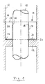
- the reference number 10 denotes the control shaft of a ball valve, with the reference number 12 the concentric wall of the housing of the ball valve, not otherwise shown.
- the - not shown - Ball of the ball valve is shown in the figure 1 below.
- Pressure element such as a gland screw, the acts on the upper end face 24 of the pack 14, the pack in pressed their sealing position.
- the pack 14 essentially consists of a block 26 of pre-pressed Graphite.
- the pack also includes 14 areas with PTFE-soaked Nickel fabric 28 and 30. The nickel fabric is preformed and is pressed together with the graphite.
- a first layer 28 made of PTFE nickel fabric is located on the inside 18 of pack 14; it extends from the lower end of the inside to a few millimeters below the top of the inside 18, so that at the top of the pack an annular, itself Inwardly extending "sealing nose" 32 made of graphite remains, the sealing abuts the control shaft.
- a second layer 30 of PTFE nickel fabric is located on the lower one Face 20 of the package 14; it extends from the inner end of the Face up to a few millimeters in front of the radially outer end of the lower one End face, so that at the outer lower edge of the pack another annular, downwardly extending "sealing nose" 34 made of graphite remains, which bears sealingly on the flange 22.
Abstract
Description
Die Erfindung betrifft eine feuerfeste Packung zum Abdichten einer Schaltwelle einer Armatur, insbesondere eines Kugelhahns, die einerseits an der Schaltwelle und andererseits an einer der Schaltwelle gegenüberliegenden, zur Schaltwelle konzentrischen Wandung dichtend anliegt. Solche Packungen werden in der Fachsprache üblicherweise auch "Firesafe-Packungen" genannt.The invention relates to a refractory packing for sealing a Switching shaft of a valve, in particular a ball valve, on the one hand on the selector shaft and on the other hand on one opposite the selector shaft, to the selector shaft concentric wall sealing. Such Packs are usually also called "Firesafe packs" called.
Armaturen, insbesondere auch Kugelhähne, die zum Absperren bzw. Regeln von brennbaren Flüssigkeiten eingesetzt werden, müssen besondere Voraussetzungen erfüllen, insbesondere müssen sie in der Regel zertifiziert sein. Wichtige Zulassungen sind beispielsweise die Firesafe-Zulassungen nach BS 6755 (British Standard) oder ISO 10497.Faucets, especially ball valves, for shutting off or regulating flammable liquids must be used Requirements, in particular they usually have to be certified his. Important approvals are, for example, the Firesafe approvals according to BS 6755 (British Standard) or ISO 10497.
Beim Brand einer Anlage darf das Medium nicht nach außen austreten bzw. es muß der Kugelhahn eine Betätigung von der Offenstellung in die Schließstellung zulassen und damit den Durchgang abdichten. Die Durchgangsdichtheit im Brandfall erreicht man dadurch, daß nach der Zerstörung der üblicherweise vorhandenen PTFE-Dichtung durch die hohe Temperatur die Kugel gegen eine spezielle Dichtkante aus Metall gedrückt wird und so ein Dichteffekt erreicht wird.When a system is fired, the medium must not escape to the outside or the ball valve must be actuated from the open position to the Allow the closed position and thus seal the passage. The continuity in the event of fire you can achieve that after the destruction the usually existing PTFE seal due to the high temperature the ball is pressed against a special sealing edge made of metal and a sealing effect is achieved.
Die Abdichtung nach außen erreicht man nach dem Stand der Technik durch den Einsatz feuerfester Dichtwerkstoffe. Die Schaltwellenabdichtung ist bei Firesafe-Hähnen allerdings ein Problem, da hier ein elastisches Material eingesetzt werden muß, um auch im normalen Betrieb einen guten Dichteffekt zu erzielen. The sealing to the outside is achieved according to the state of the art through the use of refractory sealing materials. The selector shaft seal is a problem with Firesafe taps, however, because it is an elastic one Material must be used to ensure good operation To achieve a sealing effect.
In den meisten Fällen kommen zur Abdichtung von Schaltwellen bei Firesafe-Hähnen vorgepresste Graphitpackungen zum Einsatz. Allerdings entsteht je nach Verpressungsgrad der Packung ein ganz erhebliches Drehmoment an der Schaltwelle, was im Sinne der leichtgängigen Bedienung der Armatur unerwünscht ist. Auch sind Fälle bekannt, in denen es sogar zum Festfressen, also zum Blockieren von Schaltwellen bei Kugelhähnen gekommen ist.In most cases, switching shafts for Firesafe taps are sealed pre-pressed graphite packs for use. Indeed Depending on the degree of compression of the pack, a very considerable amount arises Torque on the control shaft, which in the sense of smooth operation the valve is undesirable. Cases are also known in which it even to seize, i.e. to block switching shafts in ball valves has come.
Der Erfindung liegt daher im Wesentlichen die Aufgabe zugrunde, eine feuerfeste Packung zu schaffen, die eine leichtgängige Bedienung der Armatur sicherstellt und ein Blockieren der Schaltwelle vermeidet, ohne daß gleichzeitig die Dichtheit der Abdichtung nachteilig beeinflußt würde.The invention is therefore essentially based on the object to create a fireproof pack that enables easy operation of the Valve ensures and avoids blocking of the control shaft without that at the same time the tightness of the seal would be adversely affected.
Diese Aufgabe wird erfindungsgemäß im Wesentlichen dadurch gelöst, daß die feuerfeste Packung im wesentlichen einen Block aus vorgepreßtem Graphit umfaßt, welcher mit einer Schicht aus PTFE-Nickelgewebe verpreßt ist, wobei die Schicht aus PTFE-Nickelgewebe im Wesentlichen an der Innenseite der Packung angeordnet ist und im eingebauten Zustand der Packung an der Schaltwelle anliegt.According to the invention, this object is essentially achieved by that the refractory package is essentially a block of pre-pressed Graphite comprises, which with a layer of PTFE-nickel fabric is pressed, the layer of PTFE-nickel fabric essentially is arranged on the inside of the pack and when installed the pack rests on the selector shaft.
Das in den Graphitblock integrierte, mit PTFE getränkte Nickelgewebe gewährleistet hervorragende Gleiteigenschaften im Bereich der Schaltwelle, so daß das Drehmoment der Schaltwelle drastisch reduziert wird.The PTFE-soaked nickel mesh integrated in the graphite block ensures excellent sliding properties in the area of the selector shaft, so that the torque of the selector shaft is drastically reduced.
Eine besonders gute Dichtwirkung an der Packung wird in bevorzugter Weiterbildung der Erfindung dann erreicht, wenn sich die Schicht aus PTFE-Nickelgewebe nur über einen Teil der axialen Höhe der Packung erstreckt, so daß die Packung über einen Teilbereich ihrer Kontaktfläche mit dem Graphitmaterial dichtend an der Schaltwelle anliegt.A particularly good sealing effect on the pack is preferred Further development of the invention is achieved when the layer is made PTFE nickel mesh only over part of the axial height of the pack extends so that the pack over a portion of their contact area with the graphite material sealingly against the selector shaft.
Hierbei ist gemäß einem weiteren Merkmal der Erfindung die axiale Höhe der Schicht aus PTFE-Nickelgewebe um weniger als 10 mm kleiner als die axiale Höhe der Packung. Zweckmäßigerweise befindet sich derjenige Bereich der Packung, der ohne Zwischenschaltung der Schicht aus PTFE-Nickelgewebe unmittelbar an der Schaltwelle anliegt, an dem dem Schaltorgan der Armatur abgewandten Ende der Packung, wobei grundsätzlich auch eine andere Konfiguration möglich wäre.Here, according to a further feature of the invention, the axial height the layer of PTFE nickel fabric is less than 10 mm smaller than that axial height of the pack. That area is expediently located the pack, without the interposition of the layer of PTFE nickel fabric rests directly on the selector shaft, on the switching element end of the pack facing away from the valve, in principle another configuration would also be possible.
Im Falle eines Brandes verflüchtigt sich das PTFE im Nickelgewebe aufgrund der hohen Temperatur und aufgrund des enormen Drucks dringt dann Graphit durch die jetzt freien Maschen des Nickelgewebes und gewährleistet weiterhin die Abdichtung.In the event of a fire, the PTFE evaporates in the nickel mesh due to the high temperature and due to the enormous pressure then graphite through the now free meshes of the nickel mesh and guaranteed continue sealing.
Weitere vorteilhafte Merkmale der Erfindung ergeben sich aus den weiteren Unteransprüchen im Zusammenhang mit der nachfolgenden Beschreibung, in der ein bevorzugtes Ausführungsbeispiel der Erfindung anhand der Zeichnung näher erläutert wird.Further advantageous features of the invention result from the others Subclaims in connection with the following description, in which a preferred embodiment of the invention based on the drawing is explained in more detail.
Die einzige Figur 1 der Zeichnung zeigt in halbschematischer Darstellung einen Schnitt durch die erfindungsgemäße feuerfeste Packung im eingebauten Zustand.The only Figure 1 of the drawing shows a semi-schematic representation a section through the refractory package according to the invention in the built-in Status.
Mit der Bezugsziffer 10 ist die Schaltwelle eines Kugelhahns bezeichnet,
mit der Bezugsziffer12 die hierzu konzentrische Wandung des Gehäuses
des im Übrigen nicht näher dargestellten Kugelhahns. Die - nicht dargestellte
- Kugel des Kugelhahns befindet sich in der Darstellung gemäß Figur
1 unten.The
Eine insgesamt mit der Bezugsziffer 14 bezeichnete Firesafe-Packung in
Form eines Hohlzylinders ist auf die Schaltwelle 10 aufgeschoben und
liegt mit ihrer Aussenfläche 16 dichtend an der Wandung 12 und mit ihrer
Innenfläche 18 dichtend an der Schaltwelle 10 an. Mit ihrer unteren Stirnfläche
20 liegt die Packung auf einem von der Wandung 12 nach innen bis
nahe zur Schaltwelle ragenden Flansch 22 auf. Mittels eines nicht dargestellten
Anpressorgans wie beispielsweise einer Stopfbuchsschraube, die
auf die obere Stirnfläche 24 der Packung 14 einwirkt, wird die Packung in
ihre Dichtposition gepreßt. A Firesafe pack designated as a whole with
Die Packung 14 besteht im Wesentlichen aus einem Block 26 aus vorgepreßtem
Graphit. Weiterhin umfaßt die Packung 14 Bereiche mit PTFE-getränktem
Nickelgewebe 28 und 30. Das Nickelgewebe ist vorgeformt
und wird zusammen mit dem Graphit verpreßt.The
Eine erste Schicht 28 aus PTFE-Nickelgewebe befindet sich an der Innenseite
18 der Packung 14; sie erstreckt sich vom unteren Ende der Innenseite
bis einige wenige Millimeter unterhalb des oberen Endes der Innenseite
18, so daß am oberen Bereich der Packung eine ringförmige, sich
nach innen erstreckende "Dichtnase" 32 aus Graphit verbleibt, die dichtend
an der Schaltwelle anliegt.A
Eine zweite Schicht 30 aus PTFE-Nickelgewebe befindet sich an der unteren
Stirnseite 20 der Packung 14; sie erstreckt sich vom inneren Ende der
Stirnseite bis einige wenige Millimeter vor das radial äußere Ende der unteren
Stirnseite, so daß am äußeren unteren Rand der Packung eine weitere
ringförmige, sich nach unten erstreckende "Dichtnase" 34 aus Graphit
verbleibt, die dichtend am Flansch 22 anliegt. A
- 1010th
- SchaltwelleSelector shaft
- 1212th
- WandungWall
- 1414
- Packungpack
- 1616
- AußenflächeOutside surface
- 1818th
- InnenflächeInner surface
- 2020th
- untere Stirnflächelower face
- 2222
- Flanschflange
- 2424th
- obere Stirnflächeupper face
- 2626
- GraphitblockGraphite block
- 2828
- PTFE-NickelgewebePTFE nickel mesh
- 3030th
- PTFE-NickelgewebePTFE nickel mesh
- 3232
- DichtnaseSealing nose
- 3434
- DichtnaseSealing nose
Claims (10)
Applications Claiming Priority (2)
| Application Number | Priority Date | Filing Date | Title |
|---|---|---|---|
| DE20005320U | 2000-03-22 | ||
| DE20005320U DE20005320U1 (en) | 2000-03-22 | 2000-03-22 | Fireproof packing for sealing a valve stem |
Publications (3)
| Publication Number | Publication Date |
|---|---|
| EP1136739A2 true EP1136739A2 (en) | 2001-09-26 |
| EP1136739A3 EP1136739A3 (en) | 2002-09-18 |
| EP1136739B1 EP1136739B1 (en) | 2003-11-12 |
Family
ID=7939182
Family Applications (1)
| Application Number | Title | Priority Date | Filing Date |
|---|---|---|---|
| EP01105426A Expired - Lifetime EP1136739B1 (en) | 2000-03-22 | 2001-03-13 | Refractory spindle sealing for a valve |
Country Status (3)
| Country | Link |
|---|---|
| EP (1) | EP1136739B1 (en) |
| AT (1) | ATE254257T1 (en) |
| DE (2) | DE20005320U1 (en) |
Family Cites Families (8)
| Publication number | Priority date | Publication date | Assignee | Title |
|---|---|---|---|---|
| US1783762A (en) * | 1927-01-04 | 1930-12-02 | Yarnall Waring Co | Packing for plungers |
| GB802497A (en) * | 1955-08-03 | 1958-10-08 | Rockwell Mfg Co | Plug valves |
| DE1206242B (en) * | 1960-10-18 | 1965-12-02 | Audco Ltd | Rooster with cone pegs |
| US4462568A (en) * | 1982-03-15 | 1984-07-31 | Xomox Corporation | Valve construction and method of making the same |
| US4457491A (en) * | 1982-12-09 | 1984-07-03 | Egc Enterprises Incorp. | Extreme-temperature sealing device and annular seal therefor |
| DE8905628U1 (en) * | 1988-05-13 | 1989-07-13 | Klinger Ag, Zug, Ch | |
| DE9208943U1 (en) * | 1992-07-03 | 1992-09-10 | Kempchen & Co. Gmbh, 4200 Oberhausen, De | |
| DE69310911T2 (en) * | 1992-07-20 | 1997-08-28 | Gore & Ass | FIRE RESISTANT SPIRAL SEAL |
-
2000
- 2000-03-22 DE DE20005320U patent/DE20005320U1/en not_active Expired - Lifetime
-
2001
- 2001-03-13 AT AT01105426T patent/ATE254257T1/en not_active IP Right Cessation
- 2001-03-13 EP EP01105426A patent/EP1136739B1/en not_active Expired - Lifetime
- 2001-03-13 DE DE50100930T patent/DE50100930D1/en not_active Expired - Fee Related
Non-Patent Citations (1)
| Title |
|---|
| None |
Also Published As
| Publication number | Publication date |
|---|---|
| EP1136739B1 (en) | 2003-11-12 |
| ATE254257T1 (en) | 2003-11-15 |
| DE50100930D1 (en) | 2003-12-18 |
| DE20005320U1 (en) | 2001-05-10 |
| EP1136739A3 (en) | 2002-09-18 |
Similar Documents
| Publication | Publication Date | Title |
|---|---|---|
| DE60309339T2 (en) | HEAT AND PRESSURE RELIEF COMBINATION VALVE | |
| DE3114197A1 (en) | "VALVE WITH A FIRE-RESISTANT SEAL" | |
| DE3620539A1 (en) | POETRY | |
| DE1775691B2 (en) | COMPRESSIBLE GASKET FOR A VALVE | |
| CH693649A5 (en) | Poppet valve sealing device. | |
| DE1955438A1 (en) | Valve mechanism | |
| DE2943875A1 (en) | VALVE AND SEALING SYSTEM HERE | |
| EP0217039B1 (en) | Sealing device on a piston-cylinder arrangement, particularly to seal the valve cone on valves with pressure compensation | |
| DE102013010432A1 (en) | Thermostatic controlled valve e.g. radiator valve has indication element which is operated with respect to spindle that is movable beyond position in which valve element comes into contact with valve seat | |
| DE1450500A1 (en) | Shut-off device | |
| DE3013201A1 (en) | SHUT-OFF VALVE | |
| WO1992003673A1 (en) | Valve head | |
| CH684708A5 (en) | Flow control valve. | |
| EP3062002A1 (en) | Upper part of a valve | |
| DE3619927A1 (en) | 2-Way built-in valve | |
| EP1136739B1 (en) | Refractory spindle sealing for a valve | |
| DE102012209031A1 (en) | Gate valves | |
| WO1995008730A1 (en) | Leak-free switching process for a double seat valve and sealing arrangement for carrying out the process | |
| EP3217050B1 (en) | Seal assembly for a rotary sliding drive | |
| EP1127235A1 (en) | Cartridge for a single-handle mixer faucet | |
| EP0195178B1 (en) | Stopping and flowing valve | |
| DE19934383C2 (en) | Damping device and valve insert for such a damping device | |
| DE3240871A1 (en) | LOCKING VALVE WITH HOUSING PRESSURE RELIEF | |
| DE2249601C3 (en) | Parallel plate gate valve | |
| EP0928915B1 (en) | Double-seat valve with leak control |
Legal Events
| Date | Code | Title | Description |
|---|---|---|---|
| PUAI | Public reference made under article 153(3) epc to a published international application that has entered the european phase |
Free format text: ORIGINAL CODE: 0009012 |
|
| AK | Designated contracting states |
Kind code of ref document: A2 Designated state(s): AT BE CH CY DE DK ES FI FR GB GR IE IT LI LU MC NL PT SE TR |
|
| AX | Request for extension of the european patent |
Free format text: AL;LT;LV;MK;RO;SI |
|
| PUAL | Search report despatched |
Free format text: ORIGINAL CODE: 0009013 |
|
| AK | Designated contracting states |
Kind code of ref document: A3 Designated state(s): AT BE CH CY DE DK ES FI FR GB GR IE IT LI LU MC NL PT SE TR |
|
| AX | Request for extension of the european patent |
Free format text: AL;LT;LV;MK;RO;SI |
|
| 17P | Request for examination filed |
Effective date: 20030228 |
|
| GRAH | Despatch of communication of intention to grant a patent |
Free format text: ORIGINAL CODE: EPIDOS IGRA |
|
| AKX | Designation fees paid |
Designated state(s): AT BE CH CY DE DK ES FI FR GB GR IE IT LI LU MC NL PT SE TR |
|
| GRAS | Grant fee paid |
Free format text: ORIGINAL CODE: EPIDOSNIGR3 |
|
| GRAA | (expected) grant |
Free format text: ORIGINAL CODE: 0009210 |
|
| AK | Designated contracting states |
Kind code of ref document: B1 Designated state(s): AT BE CH CY DE DK ES FI FR GB GR IE IT LI LU MC NL PT SE TR |
|
| PG25 | Lapsed in a contracting state [announced via postgrant information from national office to epo] |
Ref country code: TR Free format text: LAPSE BECAUSE OF FAILURE TO SUBMIT A TRANSLATION OF THE DESCRIPTION OR TO PAY THE FEE WITHIN THE PRESCRIBED TIME-LIMIT Effective date: 20031112 Ref country code: NL Free format text: LAPSE BECAUSE OF FAILURE TO SUBMIT A TRANSLATION OF THE DESCRIPTION OR TO PAY THE FEE WITHIN THE PRESCRIBED TIME-LIMIT Effective date: 20031112 Ref country code: IT Free format text: LAPSE BECAUSE OF FAILURE TO SUBMIT A TRANSLATION OF THE DESCRIPTION OR TO PAY THE FEE WITHIN THE PRESCRIBED TIME-LIMIT;WARNING: LAPSES OF ITALIAN PATENTS WITH EFFECTIVE DATE BEFORE 2007 MAY HAVE OCCURRED AT ANY TIME BEFORE 2007. THE CORRECT EFFECTIVE DATE MAY BE DIFFERENT FROM THE ONE RECORDED. Effective date: 20031112 Ref country code: IE Free format text: LAPSE BECAUSE OF FAILURE TO SUBMIT A TRANSLATION OF THE DESCRIPTION OR TO PAY THE FEE WITHIN THE PRESCRIBED TIME-LIMIT Effective date: 20031112 Ref country code: GB Free format text: LAPSE BECAUSE OF FAILURE TO SUBMIT A TRANSLATION OF THE DESCRIPTION OR TO PAY THE FEE WITHIN THE PRESCRIBED TIME-LIMIT Effective date: 20031112 Ref country code: FR Free format text: LAPSE BECAUSE OF FAILURE TO SUBMIT A TRANSLATION OF THE DESCRIPTION OR TO PAY THE FEE WITHIN THE PRESCRIBED TIME-LIMIT Effective date: 20031112 Ref country code: FI Free format text: LAPSE BECAUSE OF FAILURE TO SUBMIT A TRANSLATION OF THE DESCRIPTION OR TO PAY THE FEE WITHIN THE PRESCRIBED TIME-LIMIT Effective date: 20031112 Ref country code: CY Free format text: LAPSE BECAUSE OF FAILURE TO SUBMIT A TRANSLATION OF THE DESCRIPTION OR TO PAY THE FEE WITHIN THE PRESCRIBED TIME-LIMIT Effective date: 20031112 |
|
| REG | Reference to a national code |
Ref country code: GB Ref legal event code: FG4D Free format text: NOT ENGLISH |
|
| REG | Reference to a national code |
Ref country code: CH Ref legal event code: EP |
|
| REF | Corresponds to: |
Ref document number: 50100930 Country of ref document: DE Date of ref document: 20031218 Kind code of ref document: P |
|
| REG | Reference to a national code |
Ref country code: IE Ref legal event code: FG4D Free format text: GERMAN |
|
| PG25 | Lapsed in a contracting state [announced via postgrant information from national office to epo] |
Ref country code: SE Free format text: LAPSE BECAUSE OF FAILURE TO SUBMIT A TRANSLATION OF THE DESCRIPTION OR TO PAY THE FEE WITHIN THE PRESCRIBED TIME-LIMIT Effective date: 20040212 Ref country code: GR Free format text: LAPSE BECAUSE OF FAILURE TO SUBMIT A TRANSLATION OF THE DESCRIPTION OR TO PAY THE FEE WITHIN THE PRESCRIBED TIME-LIMIT Effective date: 20040212 Ref country code: DK Free format text: LAPSE BECAUSE OF FAILURE TO SUBMIT A TRANSLATION OF THE DESCRIPTION OR TO PAY THE FEE WITHIN THE PRESCRIBED TIME-LIMIT Effective date: 20040212 |
|
| PG25 | Lapsed in a contracting state [announced via postgrant information from national office to epo] |
Ref country code: ES Free format text: LAPSE BECAUSE OF FAILURE TO SUBMIT A TRANSLATION OF THE DESCRIPTION OR TO PAY THE FEE WITHIN THE PRESCRIBED TIME-LIMIT Effective date: 20040223 |
|
| PG25 | Lapsed in a contracting state [announced via postgrant information from national office to epo] |
Ref country code: LU Free format text: LAPSE BECAUSE OF NON-PAYMENT OF DUE FEES Effective date: 20040313 Ref country code: AT Free format text: LAPSE BECAUSE OF NON-PAYMENT OF DUE FEES Effective date: 20040313 |
|
| PG25 | Lapsed in a contracting state [announced via postgrant information from national office to epo] |
Ref country code: MC Free format text: LAPSE BECAUSE OF NON-PAYMENT OF DUE FEES Effective date: 20040331 Ref country code: BE Free format text: LAPSE BECAUSE OF NON-PAYMENT OF DUE FEES Effective date: 20040331 |
|
| NLV1 | Nl: lapsed or annulled due to failure to fulfill the requirements of art. 29p and 29m of the patents act | ||
| GBV | Gb: ep patent (uk) treated as always having been void in accordance with gb section 77(7)/1977 [no translation filed] |
Effective date: 20031112 |
|
| PGFP | Annual fee paid to national office [announced via postgrant information from national office to epo] |
Ref country code: DE Payment date: 20040526 Year of fee payment: 4 |
|
| REG | Reference to a national code |
Ref country code: IE Ref legal event code: FD4D |
|
| PLBE | No opposition filed within time limit |
Free format text: ORIGINAL CODE: 0009261 |
|
| STAA | Information on the status of an ep patent application or granted ep patent |
Free format text: STATUS: NO OPPOSITION FILED WITHIN TIME LIMIT |
|
| BERE | Be: lapsed |
Owner name: S.A. *JC FABRICA DE VALVULAS Effective date: 20040331 |
|
| 26N | No opposition filed |
Effective date: 20040813 |
|
| EN | Fr: translation not filed | ||
| PG25 | Lapsed in a contracting state [announced via postgrant information from national office to epo] |
Ref country code: LI Free format text: LAPSE BECAUSE OF NON-PAYMENT OF DUE FEES Effective date: 20050331 Ref country code: CH Free format text: LAPSE BECAUSE OF NON-PAYMENT OF DUE FEES Effective date: 20050331 |
|
| PG25 | Lapsed in a contracting state [announced via postgrant information from national office to epo] |
Ref country code: DE Free format text: LAPSE BECAUSE OF NON-PAYMENT OF DUE FEES Effective date: 20051001 |
|
| REG | Reference to a national code |
Ref country code: CH Ref legal event code: PL |
|
| PG25 | Lapsed in a contracting state [announced via postgrant information from national office to epo] |
Ref country code: PT Free format text: LAPSE BECAUSE OF NON-PAYMENT OF DUE FEES Effective date: 20040412 |