EP1138889A2 - Exhaust gas purifier for internal combustion engine and method for purifying exhaust gas - Google Patents
Exhaust gas purifier for internal combustion engine and method for purifying exhaust gas Download PDFInfo
- Publication number
- EP1138889A2 EP1138889A2 EP01107620A EP01107620A EP1138889A2 EP 1138889 A2 EP1138889 A2 EP 1138889A2 EP 01107620 A EP01107620 A EP 01107620A EP 01107620 A EP01107620 A EP 01107620A EP 1138889 A2 EP1138889 A2 EP 1138889A2
- Authority
- EP
- European Patent Office
- Prior art keywords
- particulate filter
- particulates
- exhaust gas
- amount
- upstream
- Prior art date
- Legal status (The legal status is an assumption and is not a legal conclusion. Google has not performed a legal analysis and makes no representation as to the accuracy of the status listed.)
- Granted
Links
Images


Classifications
-
- B—PERFORMING OPERATIONS; TRANSPORTING
- B01—PHYSICAL OR CHEMICAL PROCESSES OR APPARATUS IN GENERAL
- B01D—SEPARATION
- B01D46/00—Filters or filtering processes specially modified for separating dispersed particles from gases or vapours
- B01D46/0039—Filters or filtering processes specially modified for separating dispersed particles from gases or vapours with flow guiding by feed or discharge devices
- B01D46/0041—Filters or filtering processes specially modified for separating dispersed particles from gases or vapours with flow guiding by feed or discharge devices for feeding
-
- B—PERFORMING OPERATIONS; TRANSPORTING
- B01—PHYSICAL OR CHEMICAL PROCESSES OR APPARATUS IN GENERAL
- B01D—SEPARATION
- B01D46/00—Filters or filtering processes specially modified for separating dispersed particles from gases or vapours
- B01D46/24—Particle separators, e.g. dust precipitators, using rigid hollow filter bodies
-
- B—PERFORMING OPERATIONS; TRANSPORTING
- B01—PHYSICAL OR CHEMICAL PROCESSES OR APPARATUS IN GENERAL
- B01D—SEPARATION
- B01D46/00—Filters or filtering processes specially modified for separating dispersed particles from gases or vapours
- B01D46/66—Regeneration of the filtering material or filter elements inside the filter
- B01D46/70—Regeneration of the filtering material or filter elements inside the filter by acting counter-currently on the filtering surface, e.g. by flushing on the non-cake side of the filter
-
- B—PERFORMING OPERATIONS; TRANSPORTING
- B01—PHYSICAL OR CHEMICAL PROCESSES OR APPARATUS IN GENERAL
- B01D—SEPARATION
- B01D53/00—Separation of gases or vapours; Recovering vapours of volatile solvents from gases; Chemical or biological purification of waste gases, e.g. engine exhaust gases, smoke, fumes, flue gases, aerosols
- B01D53/34—Chemical or biological purification of waste gases
- B01D53/92—Chemical or biological purification of waste gases of engine exhaust gases
- B01D53/94—Chemical or biological purification of waste gases of engine exhaust gases by catalytic processes
- B01D53/9404—Removing only nitrogen compounds
- B01D53/9409—Nitrogen oxides
- B01D53/9431—Processes characterised by a specific device
-
- F—MECHANICAL ENGINEERING; LIGHTING; HEATING; WEAPONS; BLASTING
- F01—MACHINES OR ENGINES IN GENERAL; ENGINE PLANTS IN GENERAL; STEAM ENGINES
- F01N—GAS-FLOW SILENCERS OR EXHAUST APPARATUS FOR MACHINES OR ENGINES IN GENERAL; GAS-FLOW SILENCERS OR EXHAUST APPARATUS FOR INTERNAL COMBUSTION ENGINES
- F01N3/00—Exhaust or silencing apparatus having means for purifying, rendering innocuous, or otherwise treating exhaust
- F01N3/02—Exhaust or silencing apparatus having means for purifying, rendering innocuous, or otherwise treating exhaust for cooling, or for removing solid constituents of, exhaust
- F01N3/021—Exhaust or silencing apparatus having means for purifying, rendering innocuous, or otherwise treating exhaust for cooling, or for removing solid constituents of, exhaust by means of filters
- F01N3/023—Exhaust or silencing apparatus having means for purifying, rendering innocuous, or otherwise treating exhaust for cooling, or for removing solid constituents of, exhaust by means of filters using means for regenerating the filters, e.g. by burning trapped particles
- F01N3/0233—Exhaust or silencing apparatus having means for purifying, rendering innocuous, or otherwise treating exhaust for cooling, or for removing solid constituents of, exhaust by means of filters using means for regenerating the filters, e.g. by burning trapped particles periodically cleaning filter by blowing a gas through the filter in a direction opposite to exhaust flow, e.g. exposing filter to engine air intake
-
- F—MECHANICAL ENGINEERING; LIGHTING; HEATING; WEAPONS; BLASTING
- F01—MACHINES OR ENGINES IN GENERAL; ENGINE PLANTS IN GENERAL; STEAM ENGINES
- F01N—GAS-FLOW SILENCERS OR EXHAUST APPARATUS FOR MACHINES OR ENGINES IN GENERAL; GAS-FLOW SILENCERS OR EXHAUST APPARATUS FOR INTERNAL COMBUSTION ENGINES
- F01N3/00—Exhaust or silencing apparatus having means for purifying, rendering innocuous, or otherwise treating exhaust
- F01N3/02—Exhaust or silencing apparatus having means for purifying, rendering innocuous, or otherwise treating exhaust for cooling, or for removing solid constituents of, exhaust
- F01N3/021—Exhaust or silencing apparatus having means for purifying, rendering innocuous, or otherwise treating exhaust for cooling, or for removing solid constituents of, exhaust by means of filters
- F01N3/023—Exhaust or silencing apparatus having means for purifying, rendering innocuous, or otherwise treating exhaust for cooling, or for removing solid constituents of, exhaust by means of filters using means for regenerating the filters, e.g. by burning trapped particles
- F01N3/0235—Exhaust or silencing apparatus having means for purifying, rendering innocuous, or otherwise treating exhaust for cooling, or for removing solid constituents of, exhaust by means of filters using means for regenerating the filters, e.g. by burning trapped particles using exhaust gas throttling means
-
- F—MECHANICAL ENGINEERING; LIGHTING; HEATING; WEAPONS; BLASTING
- F01—MACHINES OR ENGINES IN GENERAL; ENGINE PLANTS IN GENERAL; STEAM ENGINES
- F01N—GAS-FLOW SILENCERS OR EXHAUST APPARATUS FOR MACHINES OR ENGINES IN GENERAL; GAS-FLOW SILENCERS OR EXHAUST APPARATUS FOR INTERNAL COMBUSTION ENGINES
- F01N3/00—Exhaust or silencing apparatus having means for purifying, rendering innocuous, or otherwise treating exhaust
- F01N3/02—Exhaust or silencing apparatus having means for purifying, rendering innocuous, or otherwise treating exhaust for cooling, or for removing solid constituents of, exhaust
- F01N3/021—Exhaust or silencing apparatus having means for purifying, rendering innocuous, or otherwise treating exhaust for cooling, or for removing solid constituents of, exhaust by means of filters
- F01N3/023—Exhaust or silencing apparatus having means for purifying, rendering innocuous, or otherwise treating exhaust for cooling, or for removing solid constituents of, exhaust by means of filters using means for regenerating the filters, e.g. by burning trapped particles
- F01N3/025—Exhaust or silencing apparatus having means for purifying, rendering innocuous, or otherwise treating exhaust for cooling, or for removing solid constituents of, exhaust by means of filters using means for regenerating the filters, e.g. by burning trapped particles using fuel burner or by adding fuel to exhaust
- F01N3/0253—Exhaust or silencing apparatus having means for purifying, rendering innocuous, or otherwise treating exhaust for cooling, or for removing solid constituents of, exhaust by means of filters using means for regenerating the filters, e.g. by burning trapped particles using fuel burner or by adding fuel to exhaust adding fuel to exhaust gases
-
- F—MECHANICAL ENGINEERING; LIGHTING; HEATING; WEAPONS; BLASTING
- F01—MACHINES OR ENGINES IN GENERAL; ENGINE PLANTS IN GENERAL; STEAM ENGINES
- F01N—GAS-FLOW SILENCERS OR EXHAUST APPARATUS FOR MACHINES OR ENGINES IN GENERAL; GAS-FLOW SILENCERS OR EXHAUST APPARATUS FOR INTERNAL COMBUSTION ENGINES
- F01N3/00—Exhaust or silencing apparatus having means for purifying, rendering innocuous, or otherwise treating exhaust
- F01N3/02—Exhaust or silencing apparatus having means for purifying, rendering innocuous, or otherwise treating exhaust for cooling, or for removing solid constituents of, exhaust
- F01N3/021—Exhaust or silencing apparatus having means for purifying, rendering innocuous, or otherwise treating exhaust for cooling, or for removing solid constituents of, exhaust by means of filters
- F01N3/031—Exhaust or silencing apparatus having means for purifying, rendering innocuous, or otherwise treating exhaust for cooling, or for removing solid constituents of, exhaust by means of filters having means for by-passing filters, e.g. when clogged or during cold engine start
-
- F—MECHANICAL ENGINEERING; LIGHTING; HEATING; WEAPONS; BLASTING
- F01—MACHINES OR ENGINES IN GENERAL; ENGINE PLANTS IN GENERAL; STEAM ENGINES
- F01N—GAS-FLOW SILENCERS OR EXHAUST APPARATUS FOR MACHINES OR ENGINES IN GENERAL; GAS-FLOW SILENCERS OR EXHAUST APPARATUS FOR INTERNAL COMBUSTION ENGINES
- F01N3/00—Exhaust or silencing apparatus having means for purifying, rendering innocuous, or otherwise treating exhaust
- F01N3/02—Exhaust or silencing apparatus having means for purifying, rendering innocuous, or otherwise treating exhaust for cooling, or for removing solid constituents of, exhaust
- F01N3/021—Exhaust or silencing apparatus having means for purifying, rendering innocuous, or otherwise treating exhaust for cooling, or for removing solid constituents of, exhaust by means of filters
- F01N3/033—Exhaust or silencing apparatus having means for purifying, rendering innocuous, or otherwise treating exhaust for cooling, or for removing solid constituents of, exhaust by means of filters in combination with other devices
- F01N3/035—Exhaust or silencing apparatus having means for purifying, rendering innocuous, or otherwise treating exhaust for cooling, or for removing solid constituents of, exhaust by means of filters in combination with other devices with catalytic reactors, e.g. catalysed diesel particulate filters
-
- F—MECHANICAL ENGINEERING; LIGHTING; HEATING; WEAPONS; BLASTING
- F01—MACHINES OR ENGINES IN GENERAL; ENGINE PLANTS IN GENERAL; STEAM ENGINES
- F01N—GAS-FLOW SILENCERS OR EXHAUST APPARATUS FOR MACHINES OR ENGINES IN GENERAL; GAS-FLOW SILENCERS OR EXHAUST APPARATUS FOR INTERNAL COMBUSTION ENGINES
- F01N3/00—Exhaust or silencing apparatus having means for purifying, rendering innocuous, or otherwise treating exhaust
- F01N3/08—Exhaust or silencing apparatus having means for purifying, rendering innocuous, or otherwise treating exhaust for rendering innocuous
- F01N3/0807—Exhaust or silencing apparatus having means for purifying, rendering innocuous, or otherwise treating exhaust for rendering innocuous by using absorbents or adsorbents
- F01N3/0814—Exhaust or silencing apparatus having means for purifying, rendering innocuous, or otherwise treating exhaust for rendering innocuous by using absorbents or adsorbents combined with catalytic converters, e.g. NOx absorption/storage reduction catalysts
-
- F—MECHANICAL ENGINEERING; LIGHTING; HEATING; WEAPONS; BLASTING
- F01—MACHINES OR ENGINES IN GENERAL; ENGINE PLANTS IN GENERAL; STEAM ENGINES
- F01N—GAS-FLOW SILENCERS OR EXHAUST APPARATUS FOR MACHINES OR ENGINES IN GENERAL; GAS-FLOW SILENCERS OR EXHAUST APPARATUS FOR INTERNAL COMBUSTION ENGINES
- F01N3/00—Exhaust or silencing apparatus having means for purifying, rendering innocuous, or otherwise treating exhaust
- F01N3/08—Exhaust or silencing apparatus having means for purifying, rendering innocuous, or otherwise treating exhaust for rendering innocuous
- F01N3/0807—Exhaust or silencing apparatus having means for purifying, rendering innocuous, or otherwise treating exhaust for rendering innocuous by using absorbents or adsorbents
- F01N3/0821—Exhaust or silencing apparatus having means for purifying, rendering innocuous, or otherwise treating exhaust for rendering innocuous by using absorbents or adsorbents combined with particulate filters
-
- F—MECHANICAL ENGINEERING; LIGHTING; HEATING; WEAPONS; BLASTING
- F02—COMBUSTION ENGINES; HOT-GAS OR COMBUSTION-PRODUCT ENGINE PLANTS
- F02B—INTERNAL-COMBUSTION PISTON ENGINES; COMBUSTION ENGINES IN GENERAL
- F02B23/00—Other engines characterised by special shape or construction of combustion chambers to improve operation
- F02B23/02—Other engines characterised by special shape or construction of combustion chambers to improve operation with compression ignition
- F02B23/06—Other engines characterised by special shape or construction of combustion chambers to improve operation with compression ignition the combustion space being arranged in working piston
- F02B23/0672—Omega-piston bowl, i.e. the combustion space having a central projection pointing towards the cylinder head and the surrounding wall being inclined towards the cylinder center axis
-
- F—MECHANICAL ENGINEERING; LIGHTING; HEATING; WEAPONS; BLASTING
- F02—COMBUSTION ENGINES; HOT-GAS OR COMBUSTION-PRODUCT ENGINE PLANTS
- F02M—SUPPLYING COMBUSTION ENGINES IN GENERAL WITH COMBUSTIBLE MIXTURES OR CONSTITUENTS THEREOF
- F02M26/00—Engine-pertinent apparatus for adding exhaust gases to combustion-air, main fuel or fuel-air mixture, e.g. by exhaust gas recirculation [EGR] systems
- F02M26/13—Arrangement or layout of EGR passages, e.g. in relation to specific engine parts or for incorporation of accessories
- F02M26/22—Arrangement or layout of EGR passages, e.g. in relation to specific engine parts or for incorporation of accessories with coolers in the recirculation passage
- F02M26/23—Layout, e.g. schematics
-
- F—MECHANICAL ENGINEERING; LIGHTING; HEATING; WEAPONS; BLASTING
- F02—COMBUSTION ENGINES; HOT-GAS OR COMBUSTION-PRODUCT ENGINE PLANTS
- F02M—SUPPLYING COMBUSTION ENGINES IN GENERAL WITH COMBUSTIBLE MIXTURES OR CONSTITUENTS THEREOF
- F02M26/00—Engine-pertinent apparatus for adding exhaust gases to combustion-air, main fuel or fuel-air mixture, e.g. by exhaust gas recirculation [EGR] systems
- F02M26/13—Arrangement or layout of EGR passages, e.g. in relation to specific engine parts or for incorporation of accessories
- F02M26/22—Arrangement or layout of EGR passages, e.g. in relation to specific engine parts or for incorporation of accessories with coolers in the recirculation passage
- F02M26/33—Arrangement or layout of EGR passages, e.g. in relation to specific engine parts or for incorporation of accessories with coolers in the recirculation passage controlling the temperature of the recirculated gases
-
- B—PERFORMING OPERATIONS; TRANSPORTING
- B01—PHYSICAL OR CHEMICAL PROCESSES OR APPARATUS IN GENERAL
- B01D—SEPARATION
- B01D2279/00—Filters adapted for separating dispersed particles from gases or vapours specially modified for specific uses
- B01D2279/30—Filters adapted for separating dispersed particles from gases or vapours specially modified for specific uses for treatment of exhaust gases from IC Engines
-
- F—MECHANICAL ENGINEERING; LIGHTING; HEATING; WEAPONS; BLASTING
- F01—MACHINES OR ENGINES IN GENERAL; ENGINE PLANTS IN GENERAL; STEAM ENGINES
- F01N—GAS-FLOW SILENCERS OR EXHAUST APPARATUS FOR MACHINES OR ENGINES IN GENERAL; GAS-FLOW SILENCERS OR EXHAUST APPARATUS FOR INTERNAL COMBUSTION ENGINES
- F01N2570/00—Exhaust treating apparatus eliminating, absorbing or adsorbing specific elements or compounds
- F01N2570/16—Oxygen
-
- F—MECHANICAL ENGINEERING; LIGHTING; HEATING; WEAPONS; BLASTING
- F01—MACHINES OR ENGINES IN GENERAL; ENGINE PLANTS IN GENERAL; STEAM ENGINES
- F01N—GAS-FLOW SILENCERS OR EXHAUST APPARATUS FOR MACHINES OR ENGINES IN GENERAL; GAS-FLOW SILENCERS OR EXHAUST APPARATUS FOR INTERNAL COMBUSTION ENGINES
- F01N2610/00—Adding substances to exhaust gases
- F01N2610/03—Adding substances to exhaust gases the substance being hydrocarbons, e.g. engine fuel
-
- F—MECHANICAL ENGINEERING; LIGHTING; HEATING; WEAPONS; BLASTING
- F01—MACHINES OR ENGINES IN GENERAL; ENGINE PLANTS IN GENERAL; STEAM ENGINES
- F01N—GAS-FLOW SILENCERS OR EXHAUST APPARATUS FOR MACHINES OR ENGINES IN GENERAL; GAS-FLOW SILENCERS OR EXHAUST APPARATUS FOR INTERNAL COMBUSTION ENGINES
- F01N3/00—Exhaust or silencing apparatus having means for purifying, rendering innocuous, or otherwise treating exhaust
- F01N3/08—Exhaust or silencing apparatus having means for purifying, rendering innocuous, or otherwise treating exhaust for rendering innocuous
- F01N3/0807—Exhaust or silencing apparatus having means for purifying, rendering innocuous, or otherwise treating exhaust for rendering innocuous by using absorbents or adsorbents
-
- F—MECHANICAL ENGINEERING; LIGHTING; HEATING; WEAPONS; BLASTING
- F02—COMBUSTION ENGINES; HOT-GAS OR COMBUSTION-PRODUCT ENGINE PLANTS
- F02B—INTERNAL-COMBUSTION PISTON ENGINES; COMBUSTION ENGINES IN GENERAL
- F02B23/00—Other engines characterised by special shape or construction of combustion chambers to improve operation
- F02B23/02—Other engines characterised by special shape or construction of combustion chambers to improve operation with compression ignition
- F02B23/06—Other engines characterised by special shape or construction of combustion chambers to improve operation with compression ignition the combustion space being arranged in working piston
- F02B23/0618—Other engines characterised by special shape or construction of combustion chambers to improve operation with compression ignition the combustion space being arranged in working piston having in-cylinder means to influence the charge motion
- F02B23/0621—Squish flow
-
- F—MECHANICAL ENGINEERING; LIGHTING; HEATING; WEAPONS; BLASTING
- F02—COMBUSTION ENGINES; HOT-GAS OR COMBUSTION-PRODUCT ENGINE PLANTS
- F02B—INTERNAL-COMBUSTION PISTON ENGINES; COMBUSTION ENGINES IN GENERAL
- F02B23/00—Other engines characterised by special shape or construction of combustion chambers to improve operation
- F02B23/02—Other engines characterised by special shape or construction of combustion chambers to improve operation with compression ignition
- F02B23/06—Other engines characterised by special shape or construction of combustion chambers to improve operation with compression ignition the combustion space being arranged in working piston
- F02B23/0645—Details related to the fuel injector or the fuel spray
- F02B23/0669—Details related to the fuel injector or the fuel spray having multiple fuel spray jets per injector nozzle
-
- F—MECHANICAL ENGINEERING; LIGHTING; HEATING; WEAPONS; BLASTING
- F02—COMBUSTION ENGINES; HOT-GAS OR COMBUSTION-PRODUCT ENGINE PLANTS
- F02F—CYLINDERS, PISTONS OR CASINGS, FOR COMBUSTION ENGINES; ARRANGEMENTS OF SEALINGS IN COMBUSTION ENGINES
- F02F1/00—Cylinders; Cylinder heads
- F02F1/24—Cylinder heads
- F02F2001/244—Arrangement of valve stems in cylinder heads
- F02F2001/247—Arrangement of valve stems in cylinder heads the valve stems being orientated in parallel with the cylinder axis
-
- F—MECHANICAL ENGINEERING; LIGHTING; HEATING; WEAPONS; BLASTING
- F02—COMBUSTION ENGINES; HOT-GAS OR COMBUSTION-PRODUCT ENGINE PLANTS
- F02M—SUPPLYING COMBUSTION ENGINES IN GENERAL WITH COMBUSTIBLE MIXTURES OR CONSTITUENTS THEREOF
- F02M26/00—Engine-pertinent apparatus for adding exhaust gases to combustion-air, main fuel or fuel-air mixture, e.g. by exhaust gas recirculation [EGR] systems
- F02M26/02—EGR systems specially adapted for supercharged engines
- F02M26/04—EGR systems specially adapted for supercharged engines with a single turbocharger
- F02M26/05—High pressure loops, i.e. wherein recirculated exhaust gas is taken out from the exhaust system upstream of the turbine and reintroduced into the intake system downstream of the compressor
-
- F—MECHANICAL ENGINEERING; LIGHTING; HEATING; WEAPONS; BLASTING
- F02—COMBUSTION ENGINES; HOT-GAS OR COMBUSTION-PRODUCT ENGINE PLANTS
- F02M—SUPPLYING COMBUSTION ENGINES IN GENERAL WITH COMBUSTIBLE MIXTURES OR CONSTITUENTS THEREOF
- F02M26/00—Engine-pertinent apparatus for adding exhaust gases to combustion-air, main fuel or fuel-air mixture, e.g. by exhaust gas recirculation [EGR] systems
- F02M26/02—EGR systems specially adapted for supercharged engines
- F02M26/09—Constructional details, e.g. structural combinations of EGR systems and supercharger systems; Arrangement of the EGR and supercharger systems with respect to the engine
- F02M26/10—Constructional details, e.g. structural combinations of EGR systems and supercharger systems; Arrangement of the EGR and supercharger systems with respect to the engine having means to increase the pressure difference between the exhaust and intake system, e.g. venturis, variable geometry turbines, check valves using pressure pulsations or throttles in the air intake or exhaust system
-
- F—MECHANICAL ENGINEERING; LIGHTING; HEATING; WEAPONS; BLASTING
- F02—COMBUSTION ENGINES; HOT-GAS OR COMBUSTION-PRODUCT ENGINE PLANTS
- F02M—SUPPLYING COMBUSTION ENGINES IN GENERAL WITH COMBUSTIBLE MIXTURES OR CONSTITUENTS THEREOF
- F02M26/00—Engine-pertinent apparatus for adding exhaust gases to combustion-air, main fuel or fuel-air mixture, e.g. by exhaust gas recirculation [EGR] systems
- F02M26/13—Arrangement or layout of EGR passages, e.g. in relation to specific engine parts or for incorporation of accessories
- F02M26/22—Arrangement or layout of EGR passages, e.g. in relation to specific engine parts or for incorporation of accessories with coolers in the recirculation passage
- F02M26/23—Layout, e.g. schematics
- F02M26/28—Layout, e.g. schematics with liquid-cooled heat exchangers
-
- Y—GENERAL TAGGING OF NEW TECHNOLOGICAL DEVELOPMENTS; GENERAL TAGGING OF CROSS-SECTIONAL TECHNOLOGIES SPANNING OVER SEVERAL SECTIONS OF THE IPC; TECHNICAL SUBJECTS COVERED BY FORMER USPC CROSS-REFERENCE ART COLLECTIONS [XRACs] AND DIGESTS
- Y02—TECHNOLOGIES OR APPLICATIONS FOR MITIGATION OR ADAPTATION AGAINST CLIMATE CHANGE
- Y02T—CLIMATE CHANGE MITIGATION TECHNOLOGIES RELATED TO TRANSPORTATION
- Y02T10/00—Road transport of goods or passengers
- Y02T10/10—Internal combustion engine [ICE] based vehicles
- Y02T10/12—Improving ICE efficiencies
Definitions
- the invention relates to an exhaust gas purifier for an internal combustion engine and method for purifying the exhaust gas.
- particulates burn through ignition as soon as they reach about 600°C.
- the temperature of the exhaust gas in a diesel engine is usually much lower than 600°C, some measures are usually required for the purpose of heating the filter itself.
- Japanese Published Patent No. HEI 7-106290 discloses that the particulates on a filter continuously burn out approximately at 400°C, namely, at the temperature of exhaust gas during normal operation of a diesel engine if a platinum-family metal and an alkaline earth metal oxide are carried on the filter.
- this filter does not guarantee that the temperature of exhaust gas is always approximately equal to 400°C. In some operation states, a great amount of particulates may be discharged from the diesel engine, and the particulates that have not burnt out during each cycle may be gradually stacked on the filter.
- An exhaust gas purifier for an internal combustion engine comprises a particulate filter disposed in an exhaust system of the engine to collect and oxidize particulates and a reversal device for reversing upstream and downstream sides of the particulate filter.
- the particulate filter has a collecting wall for collecting particulates.
- the collecting wall has first and second collecting surfaces. The first and second collecting surfaces of the collecting wall are used alternately to collect particulates through reversal of the upstream and downstream sides of the particulate filter by the reversal device.
- the reversal device has a valve body and reverses the upstream and downstream sides of the particulate filter by switching the valve body from one position to the other position.
- At least a portion of exhaust gas bypasses the particulate filter while the valve body is being switched from one position to the other position.
- the reversal device reverses the upstream and downstream sides of the particulate filter if the amount of particulates discharged from a combustion chamber of the engine has become equal to or smaller than a set discharge amount.
- valve body is switched to reverse the upstream and downstream sides of the particulate filter when the amount of particulates discharged from the combustion chamber of the engine is equal to or smaller than the set discharge amount, there is no possibility that a great amount of particulates be included in exhaust gas. Even if a portion of exhaust gas has bypassed the particulate filter during the switching of the valve body, it is possible to reduce the amount of particulates discharged into the atmosphere.
- an active oxygen discharging agent may be-carried on the collecting wall so that active oxygen discharged from the active oxygen discharging agent oxidizes particulates.
- the active oxygen discharging agent may absorb and retain oxygen if there is an excessive amount of oxygen around, and discharge the retained oxygen in the form of active oxygen if the concentration of ambient oxygen decreases.
- the discharge amount of particulates may be determined that the discharge amount of particulates has become equal to or smaller than the set discharge amount as soon as it is judged that the engine is being decelerated, and the upstream and downstream sides of the particulate filter may be reversed.
- the reversal device may not reverse the upstream and downstream sides of the particulate filter even if the discharge amount of particulates has become equal to or smaller than the set discharge amount unless a set period has elapsed or a set running distance has been covered after the reversal of the upstream and downstream sides of the particulate filter.
- the reversal device may increase the switching speed of the valve body if it is judged during the switching of the valve body that the engine is being accelerated.
- the discharge amount of particulates has become equal to or smaller than the set discharge amount as soon as it is judged that the fuel injection amount is equal to or smaller than a set injection amount, and the upstream and downstream sides of the particulate filter may be reversed.
- the discharge amount of particulates has become equal to or smaller than the set discharge amount as soon as it is judged that the depression amount of an accelerator pedal is equal to or smaller than a set depression amount, and the upstream and downstream sides of the particulate filter may be reversed.
- the discharge amount of particulates may be determined that the discharge amount of particulates has become equal to or smaller than the set discharge amount as soon as it is judged that a clutch pedal has been depressed, and the upstream and downstream sides of the particulate filter may be reversed.
- An exhaust gas purifier for an internal combustion engine comprises a particulate filter disposed in an exhaust system of the engine to collect and oxidize particulates and a reversal device for reversing upstream and downstream sides of the particulate filter.
- the particulate filter has a collecting wall for collecting particulates.
- the collecting wall has first and second collecting surfaces. The first and second collecting surfaces of the collecting wall are used alternately to collect particulates through reversal of the upstream and downstream sides of the particulate filter by the reversal device.
- the reversal device has a valve body and reverses the upstream and downstream sides of the particulate filter by switching the valve body from one position to the other position.
- At least a portion of exhaust gas bypasses the particulate filter while the valve body is being switched from one position to the other position.
- the reversal device reverses the upstream and downstream sides of the particulate filter at a switching speed corresponding to an operation state of the engine.
- the aforementioned construction makes it possible to prevent the clogging of the particulate filter through the reversal of the upstream and downstream sides of the particulate filter.
- the valve body is switched to reverse the upstream and downstream sides of the particulate filter at a switching speed corresponding to an operation state of the engine. Therefore, if the switching speed is reduced when almost no particulates are included in low-temperature exhaust gas, for example, when the engine is being decelerated, it is possible to suppress a decrease in the temperature of the particulate filter without discharging particulates into the atmosphere. If the switching speed is increased when particulates are included in exhaust gas, it is possible to reduce the amount of particulates discharged into the atmosphere.
- an active oxygen discharging agent may be carried on the collecting wall so that active oxygen discharged from the active oxygen discharging agent oxidizes particulates.
- the active oxygen discharging agent may absorb and retain oxygen if there is an excessive amount of oxygen around, and discharge the retained oxygen in the form of active oxygen if the concentration of ambient oxygen decreases.
- Fig. 1 is a schematic longitudinal cross-sectional view of a diesel engine having an exhaust gas purifier according to the invention.
- Fig. 2 is an enlarged longitudinal cross-sectional view of a combustion chamber shown in Fig. 1.
- Fig. 3 is a bottom view of a cylinder head shown in Fig. 1.
- Fig. 4 is a side cross-sectional view of a combustion chamber.
- Fig. 5 shows the lifts of intake and exhaust valves and fuel injection.
- Fig. 6 mainly shows the generation amounts of smoke and NO x .
- Fig. 7 shows combustion pressures.
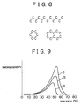
- Fig. 8 shows fuel molecules.
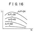
- Fig. 9 shows the relation between generation amounts of smoke and EGR rates.
- Fig. 10 shows the relation between fuel injection amounts and amounts of mixture gas.
- Fig. 12 shows the outputs of an air-fuel ratio sensor.
- Fig. 13 mainly shows the opening degrees of a throttle valve.
- Fig. 1 is a schematic longitudinal cross-sectional view of a four-stroke diesel engine having an exhaust gas purifier according to the invention.
- Fig. 2 is an enlarged longitudinal cross-sectional view of a combustion chamber of the diesel engine shown in Fig. 1.
- Fig. 3 is a bottom view of a cylinder head of the diesel engine shown in Fig. 1.
- an intake port 8 is coupled to a surge tank 12 through a relevant intake branch pipe 11, and the surge tank 12 is coupled to an air cleaner 14 through an intake duct 13.
- a throttle valve 16 driven by an electric motor 15 is disposed in an intake duct 18.
- an exhaust port 10 is connected to an exhaust manifold 17.
- an air-fuel ratio sensor 21 is disposed in the exhaust manifold 17.
- the exhaust manifold 17 and the surge tank 12 are coupled to each other through an EGR passage 22, and an electrically controlled EGR control valve 23 is disposed in the EGR passage 22.
- a cooling unit 24 is disposed around the EGR passage 22 to cool the EGR gas flowing through the EGR passage 22.
- engine coolant is introduced into the cooling unit 24 so that the EGR gas is cooled by the engine coolant.
- each fuel injection valve 6 is coupled to a fuel reservoir, namely, a so-called common rail 26 through a fuel supply pipe 25.
- Fuel is supplied to the common rail 26 from an electrically controlled fuel pump 27 whose discharge amount is variable.
- the fuel supplied to the common rail 26 is supplied to the fuel injection valve 6 through each fuel supply pipe 25.
- a fuel pressure sensor 28 for detecting the fuel pressure in the common rail 26 is mounted to the common rail 26. Based on the output signal from the fuel pressure sensor 28, the discharge amount of the fuel pump 27 is controlled such that the fuel pressure in the common rail 26 becomes equal to a target fuel pressure.
- the output signals from the air-fuel ratio sensor 21 and the fuel pressure sensor 28 are inputted to an electronic control unit 30.
- a load sensor 41 generating the output voltage proportional to the depression amount L of an accelerator pedal 40 is connected to the accelerator pedal 40.
- the output signal from the load sensor 41 is also inputted to the electronic control unit 30.
- the output signal from a crank angle sensor 42 which generates an output pulse every time a crank shaft rotates for example by 30°CA, is also inputted to the electronic control unit 30.
- the electronic control unit 30 operates the fuel injection valve 6, the electric motor 15, the EGR control valve 23 and the fuel pump 27 based on various signals.
- a ROM (not shown in figures) is built into the electronic control unit 30.
- the fuel injection valve 6 is constructed of a hole nozzle having six nozzle holes. Fuel sprays F are injected from the nozzle holes of the fuel injection valve 6 at equal angular intervals and slightly downwardly with respect to a horizontal plane. As shown in Fig. 3, two of the six fuel sprays F fly along the lower face of a valve body of each exhaust valve 9. Figs. 2, 3 show fuel injection in the late stage of a compression stroke. At this moment, the fuel sprays F travel towards the inner periphery of a cavity 5a and are then ignited and burnt.
- Fig. 4 shows a case where additional fuel is injected from the fuel injection valve 6 when the lift of the exhaust valve 9 is at its maximum in an exhaust stroke. That is, as shown in Fig. 5, main injection Qm is carried out in the proximity of a compression top dead center and additional fuel Qa is then injected in the middle of an exhaust stroke.
- the fuel sprays F traveling in the direction of the valve body of the exhaust valve 9 head towards a space between the back face of the bevel of the exhaust valve 9 and the exhaust port 10.
- two of the six nozzle holes of the fuel injection valve 6 are configured such that the fuel sprays F head towards the space between the back face of the bevel of the exhaust valve 9 and the exhaust port 10 upon injection of the additional fuel Qa when the exhaust valve 9 is open.
- the fuel sprays F then hit the back face of the bevel of the exhaust valve 9, are reflected thereby, and head towards the exhaust port 10.
- Fig. 6 shows an experimental example indicative of changes in the output torque and changes in the discharge amounts of smoke, HC, CO and NOx when the air-fuel ratio A/F (the axis of abscissa in Fig. 6) is changed by changing the opening degree of the throttle valve 16 and the EGR rate.
- this experimental example demonstrates that the EGR rate increases with decreases in the air-fuel ratio A/F and that the EGR rate is equal to or higher than 65% when the air-fuel ratio is equal to or lower than the stoichiometric air-fuel ratio ( ⁇ 14.6).
- the generation amount of smoke starts increasing when the EGR rate approaches 40% and the air-fuel ratio A/F reaches approximately 30. Then if the EGR rate is further enhanced to reduce the air-fuel ratio A/F, the generation amount of smoke increases abruptly and reaches its peak. Then if the EGR rate is further enhanced to reduce the air-fuel ratio A/F, the generation amount of smoke decreases abruptly and becomes approximately equal to zero when the EGR rate becomes equal to or higher than 65% and the air-fuel ratio A/F approaches 15.0. In other words, hardly no smoke is generated. At this moment, the main torque of the engine decreases slightly and the generation amount of NO x becomes considerably small. On the other hand, at this moment, the generation amounts of HC and CO start increasing.
- the circumstances are slightly different if there is fuel in the mixture gas composed of a great amount of inactive gas and air.
- fuel vapors are diffused around, react with the oxygen mixed into inactive gas, and burn.
- ambient inactive gas absorbs the combustion heat, the combustion temperature does not rise appreciably. Namely, it is possible to keep the combustion temperature low.
- the presence of inactive gas plays an important role in reducing the combustion temperature and the endothermic effect of inactive gas makes it possible to keep the combustion temperature low.
- the maintaining of the temperature of fuel and ambient gas lower than a temperature where soot is produced requires such an amount of inactive gas that can absorb heat sufficiently. Accordingly, the required amount of inactive gas increases as the amount of fuel increases. In this case, the endothermic effect is strengthened in proportion to the specific heat of inactive gas. Thus, it is preferable to use inactive gas with a great specific heat. In this respect, since CO 2 and EGR gas have a relatively great specific heat, it is possible to conclude that EGR gas can be desirably used as inactive gas.
- Fig. 9 shows the relation between EGR rates and generation amounts of smoke when EGR gas is used as inactive gas and the cooling degree of EGR gas is changed.
- Fig. 9 shows curves A, B and C.
- the curve A indicates a case where the temperature of EGR gas is maintained approximately at 90°C by intensively cooling EGR gas.
- the curve B indicates a case where EGR gas is cooled by a compact cooling unit.
- the curve C indicates a case where EGR is not cooled forcibly.
- Fig. 9 shows the generation amounts of smoke when the engine load is relatively high. If the engine load lowers, the EGR rate where the generation amount of soot reaches its peak decreases slightly, and the lower limit of the EGR rate where hardly no soot is generated also decreases slightly. The lower limit of the EGR rate where hardly no soot is generated changes depending on the cooling degree of EGR gas and the engine load.
- Fig. 10 shows the amount of the mixture gas composed of EGR gas and air required for maintaining the temperature of fuel and ambient gas lower than a temperature where soot is produced, the ratio of air to the mixture gas, and the ratio of EGR gas to the mixture gas, in the case where EGR gas is used as inactive gas.
- the axis of ordinate represents the total amount of the intake gas that can be sucked into the combustion chamber 5
- a chain line Y represents the total amount of the intake gas that can be sucked into the combustion chamber 5 when the supercharging operation is not performed.
- the axis of abscissa represents the required load and Z1 represents a low-load operation range.
- the ratio of air namely, the amount of air in mixed gas indicates the amount of air required for complete combustion of injected fuel. Namely, in the case shown in Fig. 10, the ratio of the amount of air to the amount of injected fuel is equal to the stoichiometric air-fuel ratio.
- the ratio of EGR gas namely, the amount of EGR gas in mixture gas indicates the minimum amount of EGR gas required for maintaining the temperature of fuel and ambient gas lower than a temperature where soot is formed, during combustion of injected fuel. This minimum required amount of EGR gas corresponds to the EGR rate that is approximately equal to or higher than 55%. In the embodiment shown in Fig.
- the EGR rate is equal to or higher than 70%. That is, if it is assumed that the total amount of the intake gas sucked into the combustion chamber 5 is indicated by a solid line X shown in Fig. 10 and that the ratios of the amount of air and the amount of EGR gas to the total amount of intake gas X are as shown in Fig. 10, the temperature of fuel and ambient gas is lower than a temperature where soot is produced. Consequently, no soot is generated. The generation amount of NO x at this moment is approximately equal to or smaller than 10 p.p.m and is therefore considerably small.
- the amount of heat absorbed by EGR gas needs to be increased in order to maintain the temperature of fuel and ambient gas lower than a temperature where soot is produced.
- the amount of EGR gas needs to be increased as the amount of injected fuel increases. In other words, the amount of EGR gas needs to be increased as the required load increases.
- the combustion temperature is kept low, the excessive fuel does not grow into soot. Consequently, no soot is produced.
- the generation amount of NO x is also considerably small.
- a small amount of soot is produced in response to a rise in the combustion temperature when the average air-fuel ratio is lean or when the air-fuel ratio is equal to the stoichiometric air-fuel ratio.
- the combustion temperature is kept low, no soot is generated. Furthermore, the generation amount of NO x is also considerably small.
- the first combustion namely, the low-temperature combustion refers to combustion of a type wherein the amount of inactive gas in the combustion chamber is greater than a most inappropriate amount of inactive gas corresponding to a maximum generation amount of soot and wherein hardly no soot is generated
- the second combustion namely, the conventional combustion refers to combustion of a type wherein the amount of inactive gas in the combustion chamber is smaller than a most inappropriate amount of inactive gas corresponding to a maximum generation amount of soot.
- the required load L exceeds the first border X(N) expressed as a function of the engine speed N when the low-temperature combustion is carried out with the engine in the first operation range I, it is judged that the operation range has shifted to the second operation range II, and the conventional combustion is carried out. If the required load L drops below the second border Y(N) expressed as a function of the engine speed N, it is judged that the operation range has shifted to the first operation range I, and the low-temperature combustion is carried out again.
- Fig. 12 shows the outputs of the air-fuel ratio sensor 21.
- the output current I of the air-fuel ratio sensor 21 changes in accordance with the air-fuel ratio A/F.
- the outline of operation control in the first operation range I and the second operation range II will be described.
- Fig. 13 shows how the opening degree of the throttle valve 16, the opening degree of the EGR control valve 23, the EGR rate, the air-fuel ratio, the injection timing and the injection amount change as the required load L changes.
- the opening degree of the throttle valve 16 gradually increases approximately from its full-closed state to its half-open state as the required load L increases, and the opening degree of the EGR control valve 23 gradually increases approximately from its full-closed state to its full-open state as the required load L increases.
- the EGR rate is approximately equal to 70%
- the air-fuel ratio is slightly lean.
- the opening degrees of the throttle valve 16 and the EGR control valve 23 are controlled such that the EGR rate becomes approximately equal to 70% and that the air-fuel ratio becomes slightly lean.
- the air-fuel ratio is controlled to a target lean air-fuel ratio by correcting the opening degree of the EGR control valve 23 based on the output signal from the air-fuel ratio sensor 21.
- fuel injection is carried out before a compression top dead center TDC.
- the injection start timing ⁇ S is retarded as the required load L increases.
- the injection end timing ⁇ E is also retarded as the injection start timing ⁇ S is retarded.
- the throttle valve 16 is opened approximately to its full-open state and the EGR control valve 23 is also closed approximately to its full-closed state. If the throttle valve 16 is closed approximately to its full-close state, the pressure in the combustion chamber 5 at the beginning of compression decreases, and therefore, the compression pressure decreases. If the compression pressure decreases, the compression work done by a piston 4 decreases, and therefore, the oscillation of an engine body 1 decreases. That is, during idling operation, the throttle valve 16 is closed approximately to its full-closed state to damp the oscillation of the engine body 1.
- the opening degree of the throttle valve 16 is increased stepwise from its half-open state toward its full-open state.
- the EGR rate is reduced stepwise approximately from 70% to 40% or less, and the air-fuel ratio is increased stepwise. That is, since the EGR rate exceeds an EGR rate range (Fig. 9) where a great amount of smoke is generated, a shift of the operation range of the engine from the first operation range I to the second operation range II does not cause generation of a great amount of smoke.
- the conventional combustion is carried out.
- the conventional combustion causes generation of a small amount of soot and NO x but is higher in thermal efficiency than the low-temperature combustion.
- the injection amount is reduced stepwise as shown in Fig. 13.
- the throttle valve 16 In the second operation range II, the throttle valve 16 is mostly maintained in its full-open state, and the opening degree of the EGR control valve 23 is gradually reduced as the required load L is increased.
- the EGR rate decreases as the required load L increases, and the air-fuel ratio decreases as the required load L increases. However, the air-fuel ratio remains lean even if the required load L has increased.
- the injection start timing ⁇ S is in the proximity of the compression top dead center TDC.
- Fig. 14 shows the air-fuel ratios A/F in the first operation range I.
- the air-fuel ratio is lean in the first operation range I, and the air-fuel ratio A/F becomes leaner as the required load L decreases in the first operation range I.
- the heat release value resulting from combustion decreases as the required load L decreases.
- the required load L decreases, the possibility of carrying out the low-temperature combustion increases even if the EGR rate has been reduced.
- the air-fuel ratio increases if the EGR rate is reduced.
- the air-fuel ratio A/F is increased as the required load L decreases.
- the fuel consumption rate is enhanced as the air-fuel ratio A/F increases. Accordingly, in this embodiment, in order to make the air-fuel ratio as lean as possible, the air-fuel ratio A/F is increased as the required load L decreases.
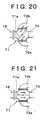
- the target opening degrees ST of the throttle valve 16 required for making the air-fuel ratio equal to the target air-fuel ratios shown in Fig. 14 are stored in advance in the ROM in the form of a map as a function of the required load L and the engine speed N as shown in Fig. 15A.
- the target opening degrees SE of the EGR control valve 23 required for making the air-fuel ratio equal to the target air-fuel ratios shown in Fig. 14 are stored in advance in the ROM in the form of a map as a function of the required load L and the engine speed N as shown in Fig. 15B.
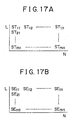
- Fig. 16 shows the target air-fuel ratios during the second combustion, namely, the conventional combustion.
- the target opening degrees ST of the throttle valve 16 required for making the air-fuel ratio equal to the target air-fuel ratios are stored in advance in the ROM in the form of a map as a function of the required load L and the engine speed N as shown in Fig. 17A.
- the target opening degrees SE of the EGR control valve 23 required for making the air-fuel ratio equal to the target air-fuel ratios are stored in advance in the ROM in the form of a map as a function of the required load L and the engine speed N as shown in Fig. 17B.
- the operation of the diesel engine according to this embodiment is switched between the first combustion, namely, the low-temperature combustion and the second combustion, namely, the conventional combustion based on the depression amount L of the accelerator pedal 40 and the engine speed N.
- the opening degrees of the throttle valve 16 and the EGR valve are controlled with reference to the map shown in Fig. 15 or Fig. 17.
- Fig. 18 is a plan view of an exhaust gas purifier.
- Fig. 19 is a side view of the exhaust gas purifier.
- the exhaust gas purifier has a change-over portion 71 connected to the downstream side of the exhaust manifold 17 through an exhaust pipe 18, a particulate filter 70, a first connecting portion 72a for connecting one side of the particulate filter 70 to the change-over portion 71, a second connecting portion 72b for connecting the other side of the particulate filter 70 to the change-over portion 71, and an exhaust passage 73 downstream of the change-over portion 71.
- the change-over portion 71 has a valve body 71a, which can block the flow of exhaust gas in the change-over portion 71.
- Fig. 20 shows a second block position of the valve body 71a.
- the upstream side of the change-over portion 71 communicates with the second connecting portion 72b, and the downstream side of the change-over portion 71 communicates with the first connecting portion 72a.
- exhaust gas flows from the other side to one side of the particulate filter 70 as indicated by arrows in Fig. 20.
- the valve body 71a from one of the first and second block positions to the other, it becomes possible to reverse the direction of the exhaust gas flowing into the particulate filter 70, namely, to reverse the upstream and downstream sides of the particulate filter 70.
- exhaust gas purifier while the valve body 71a is rotated from one of the first and second block positions to the other with a view to reversing the upstream and downstream sides of the particulate filter, exhaust gas is discharged into the atmosphere without passing through the particulate filter as shown in Fig. 21.
- Figs. 22A, 22B show the structure of the particulate filter 70.
- Fig. 22A is a front view of the particulate filter 70
- Fig. 22B is a side cross-sectional view of the particulate filter 70.
- the particulate filter 70 has an elliptical front face, is designed as a wall-flow type of a honeycomb structure formed of a porous material such as cordierite and has a multitude of axial spaces divided by a multitude of partitions 54 extending in the axial direction. One of two adjacent ones of the axial spaces is closed on the downstream side by a cork 52, and the other is closed on the upstream side by a cork 53.
- one of the two adjacent axial spaces serves as an inflow passage 50, and the other serves as an outflow passage 51.
- exhaust gas inevitably passes through the partitions 54.
- the particulates included in exhaust gas are much smaller than pores in the partitions 54. These particulates hit the upstream-side surfaces of the partitions 54 and the surfaces of the pores in the partitions 54 and are then collected.
- the partitions 54 function as collecting walls for collecting particulates.
- alkaline metals or alkaline earth metals that are higher in ionization tendency than calcium Ca, namely, potassium K, lithium Li, cesium Cs, rubidium Rb, barium Ba and strontium Sr as the active oxygen discharging agent.
- exhaust gas includes a great amount of excessive air. That is, if the ratio of air and fuel supplied to an intake passage and a combustion chamber is referred to as the air-fuel ratio of exhaust gas, the air-fuel ratio is lean. Because NO is generated in the combustion chamber, exhaust gas includes NO. Fuel includes sulfur S, which reacts with oxygen in the combustion chamber and turns into SO 2 . Therefore, exhaust gas includes SO 2 . Accordingly, the exhaust gas including excessive oxygen, NO and SO 2 flows into the upstream side of the particulate filter 70.
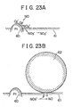
- FIGs. 23A, 23B schematically show an exhaust gas contact surface of the particulate filter 70 in an enlarged manner.
- An active oxygen discharging agent 61 includes potassium K.
- Exhaust gas includes a great amount of excessive oxygen as described above. Therefore, if exhaust gas contacts the exhaust gas contact surface in the particulate filter, oxygen elements O 2 adhere to the surface of platinum Pt in the form of O 2 - or O 2- as shown in Fig. 23A.
- the NO in exhaust gas reacts with O 2 - or O 2- on the surface of platinum Pt and turns into NO 2 (2NO + O 2 ⁇ 2NO 2 ). A portion of the produced NO 2 is then absorbed into the active oxygen discharging agent 61 while being oxidized on platinum Pt. Coupled with potassium K, NO 2 is diffused into the active oxygen discharging agent 61 in the form of nitrate ion NO 3 - as shown in Fig. 23A, and produces potassium nitrate KNO 3 .
- the particulate filter 70 absorbs the noxious NO x included in exhaust gas and thereby makes it possible to substantially reduce the amount of the NO x discharged into the atmosphere.
- exhaust gas also includes SO 2 , which is also absorbed into the active oxygen discharging agent 61 by a mechanism similar to that of NO. That is, as described above, oxygen elements O 2 adhere to the surface of platinum Pt in the form of O 2 - or O 2- , and the SO 2 in exhaust gas reacts with O 2 - or O 2- on the surface of platinum Pt and turns into SO 3 .
- a portion of the produced SO 3 is absorbed into the active oxygen discharging agent 61 while being further oxidized on platinum Pt. Coupled with potassium K, SO 3 is diffused into the active oxygen discharging agent 61 in the form of sulfate ion SO 4 2- and produces potassium sulfate K 2 SO 4 . In this manner, potassium nitrate KNO 3 and potassium sulfate K 2 SO 4 are produced.
- the oxygen O moving towards the contact surface between the particulate 62 and the active oxygen discharging agent 61 is decomposed from compounds such as potassium nitrate KNO 3 and potassium sulfate K 2 SO 4 .
- the oxygen O decomposed from a compound is high in energy level and demonstrates an extremely high degree of activity. Accordingly, the oxygen moving towards the contact surface between the particulate 62 and the active oxygen discharging agent 61 is active oxygen O. If the active oxygen elements O contact the particulate 62, the particulate 62 is oxidized without generating luminous flames.
- the time required for the particulates to be moved through oxidation on the particulate filter ranges from a few minutes to dozen of minutes.
- NO x are diffused in the active-oxygen discharge agent 61 in the form of nitrate ion NO 3 - while repeatedly connecting to and separating from oxygen atoms. Active oxygen is generated also during this period.
- the particulates 62 are oxidized also by this active oxygen. Further, the particulates 62 that have thus adhered onto the particulate filter are oxidized by active oxygen O but are oxidized also by oxygen in exhaust gas.
- Platinum Pt and the active oxygen discharging agent 61 are activated as the temperature of the particulate filter rises.
- the amount of the active oxygen O discharged by the active oxygen discharging agent 61 per unit time increases as the temperature of the particulate filter rises.
- particulates are more likely to be removed by oxidation as the temperature of the particulates themselves rises. Accordingly, the amount of the particulates that can be removed through oxidation on the particulate filter per unit time without generating luminous flames increases as the temperature of the particulate filter rises.
- the amount of the particulates discharged from a combustion chamber per unit time is referred to as the amount M of discharged particulates. If the amount M of discharged particulates is smaller than the amount G of the particulates that can be removed through oxidation as in a range I shown in Fig. 24, most particulates discharged from the combustion chamber are removed through oxidation in the particulate filter within a short time without generating luminous flames as soon as they are collected by the particulate filter.
- the time required for the particulates to be moved through oxidation on the particulate filter ranges from a few minutes to dozen of minutes.
- Figs. 25A through 25C show how a particulate is oxidized in such a case. That is, in the case where the amount of active oxygen is insufficient to oxidize all the particulates, if the particulate 62 adheres to the active oxygen discharging agent 61 as shown in Fig.
- the residual particulate portion 63 is gradually transformed into a carbon material, which is unlikely to be oxidized. If the upstream-side surface of the particulate filter is covered with the residual particulate portion 63, the oxidation effect of NO and SO 2 by platinum Pt and the discharging effect of active oxygen by the active oxygen discharging agent 61 are weakened.
- the residual particulate portion 63 can be gradually oxidized over a long period of time. However, if one particulate 64 after another is stacked on the residual particulate portion 63, namely, if particulates are stacked and laminated, the particulates are not oxidized by active oxygen.
- particulates Even if the particulates are likely to be oxidized, they are not oxidized by active oxygen because they are spaced apart from platinum Pt and the active oxygen discharging agent. Accordingly, one particulate after another is stacked on the particulate 64. Namely, if the amount M of discharged particulates remains greater than the amount G of the particulates that can be removed through oxidation, particulates are stacked and laminated on the particulate filter.
- particulates are oxidized on the particulate filter within a short period of time without generating luminous flames in the range I shown in Fig. 24, and particulates are stacked and laminated on the particulate filter in the range II shown in Fig. 24.
- the relation between the amount M of discharged particulates and the amount G of the particulates that can be removed through oxidation is set in the range I, it becomes possible to prevent particulates from being stacked on the particulate filter. If the discharged particulate amount M is thus maintained smaller than the amount of particulates G that can be removed by oxidation, no particulate is deposited on the particulate filter in a laminated manner.
- the pressure loss of exhaust gas flow in the particulate filter scarcely changes and is maintained at a substantially constant minimum pressure loss value.
- the decrease in engine output can be maintained at its minimum value.
- this is not always ensured, and particulates may be stacked on the particulate filter if no countermeasure is taken.
- the electronic control unit 30 performs change-over control of the valve body 71a in accordance with a first flowchart shown in Fig. 26 and prevents particulates from being stacked on the particulate filter. This flowchart is repeated at intervals of a predetermined period.
- Step 101 it is judged in Step 101 whether or not the cumulative time t is equal to or longer than a set time ts.
- the cumulative time t represents a time that has elapsed after the switching of the valve body 71a. If the result of the judgment in Step 101 is NO, the cumulative time t is cumulated in Step 105 and the routine is terminated. If the result of the judgment in Step 101 is YES, the operation proceeds to Step 102.
- Step 102 It is judged in Step 102 whether or not an accelerator pedal has been released by a limit switch or the like mounted thereto while the vehicle is traveling. If the result of the judgment in Step 102 is NO, the cumulative time t is cumulated in Step 105 and the routine is terminated.
- Step 102 If the result of the judgment in Step 102 is YES, the valve body 71a is switched in Step 103. In other words, the upstream and downstream sides of the particulate filter are reversed. Then the cumulative time t is reset to 0 in Step 104. The cumulative time t is again cumulated in Step 105 and the routine is terminated.
- Fig. 27 is an enlarged cross-sectional view of the partition 54 of the particulate filter. While the vehicle is traveling, operation may be performed in the range II shown in Fig. 24. As indicated by grids in Fig. 27A, the upstream-side surfaces and the gas-flow facing surfaces of the partition 54, which is mainly hit by exhaust gas, hit particulates, serve as one collecting surface to collect the particulates, and remove them through oxidation using an active oxygen discharging agent. The removal of the particulates through oxidation is sometimes so insufficient that some particulates may exist as residues. At this moment, the exhaust gas resistance of the particulate filter does not adversely affect the traveling of the vehicle.
- particulates in exhaust gas adhere to the other collecting surface of the partition 54 which has been switched to the upstream side due to the back-flow of exhaust gas, namely, the upstream-side surfaces and the gas-flow facing surfaces of the partition 54 which is mainly hit by exhaust gas at the moment (on the other side of one collecting surface), and are removed through oxidation by the active oxygen discharged from the active oxygen discharging agent.
- a portion of the active oxygen discharged from the active oxygen discharging agent at the time of the removal through oxidation moves towards the downstream side together with exhaust gas, and removes, through oxidation, the particulates that still remain even after the back-flow of exhaust gas.
- the residual particulates on one collecting surface of the partition is reached not only by the active oxygen discharged from the collecting surface but also by the remaining active oxygen that has been used to remove through oxidation the particulates on the other collecting surface of the partition due to the back-flow of exhaust gas, together with exhaust gas.
- the back-flow of exhaust gas ensures that active oxygen also reaches the particulates stacked on the residual particulates and that no more particulates are stacked. Therefore, the stacked particulates are gradually removed through oxidation. A sufficient amount of them can be removed through oxidation if a certain period of time remains until the flow of exhaust gas is reversed next time.
- the valve body is switched every time the accelerator pedal is released while the vehicle is traveling. Therefore, for example, even when the vehicle goes up a slope over a long period of time, the accelerator pedal is often released with the intention of decelerating the vehicle. In other words, the valve body does not remain untouched for a long time. Therefore, even if operation is often performed in the range II shown in Fig. 24, there is no possibility that a great amount of particulates be stacked on the particulate filter when the valve body is switched or that the particulates stacked on the particulate filter remain untouched for a long time and be transformed into a carbon material which is unlikely to be oxidized.
- the residual particulates and the stacked particulates can be reliably removed through oxidation by merely reversing the flow of exhaust gas. Further, since a great amount of stacked particulates burn at a time, the possibility of causing a problem such as dissolution of the particulate filter resulting from the generation of a great amount of combustion heat is eliminated.
- the reversal of the upstream and downstream sides of the particulate filter is highly effective in removing the residual particulates and the stacked particulates through oxidation.
- a portion of exhaust gas bypasses the particulate filter 70. If the amount of particulates discharged from the combustion chamber of the engine is greater than a set discharge amount at this moment, a relatively great amount of particulates are included in exhaust gas. These particulates are discharged into the atmosphere.
- the valve body is switched when the accelerator pedal is released, and at this moment, the supply of fuel is stopped with the intention of decelerating the vehicle, or only a small amount of fuel is being injected. Therefore, the amount of the particulates discharged from the combustion chamber of the engine is equal to or smaller than the set discharge amount, and almost no particulates are included in exhaust gas.
- the valve body if the cumulative time t since the last release of the accelerator pedal has not reached the set time when the accelerator pedal is released, the valve body is not switched.
- the release of the accelerator pedal is detected to judge whether or not the engine is being decelerated.
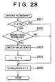
- Fig. 28 shows a second flowchart that is used instead of the first flowchart. The following description will be limited to the difference between the first and second flowcharts.
- the second flowchart if the cumulative running distance D is equal to or longer than a set running distance Ds, it is judged whether or not a brake pedal has been depressed by a limit switch or the like mounted thereto while the vehicle is traveling. If the result of the judgment is YES, the valve body is switched and the upstream and downstream sides of the particulate filter are reversed. There is no need to provide a new limit switch. Namely, it is also possible to use a switch for lighting a brake lamp as the limit switch.
- the valve body is not switched.
- This does not limit the invention but makes it possible to prevent the valve body from being switched unnecessarily in the case where the brake pedal is depressed frequently, prolong the life span of the valve body and an actuator for driving the valve body, and reduce the frequency of generation of noise when the valve body is driven.
- the cumulative running distance in the second flowchart can be replaced by the cumulative time in the first flowchart. Conversely, the cumulative time in the first flowchart can be replaced by the cumulative running distance.
- the temperature of exhaust gas is considerably low. If the low-temperature exhaust gas passes through the particulate filter, the temperature of the particulate filter falls and the amount of the particulates that can be removed through oxidation decreases. Thus, in the first and second flowcharts, if even a portion of the low-temperature exhaust gas has bypassed the particulate filter through the switching of the valve body, the fall in the temperature of the particulate filter can be prevented effectively. Accordingly, it is preferable to reduce the switching speed of the valve body to ensure that much of the low-temperature exhaust gas bypasses the particulate filter.
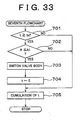
- Step 301 it is judged in Step 301 whether or not the switching of the valve body has been started by the first or second flowchart. If the result of the judgment is NO, the routine is terminated immediately. However, if the switching of the valve body has been switched, it is judged in Step 302 whether or not the accelerator pedal has been depressed. If the result of the judgment is NO, the switching speed of the valve body remains low and the switching of the valve body is continued.
- a low switching speed of the valve body means not only that the valve body continuously moves with a small amount of displacement per unit time but also that the valve body moves intermittently.
- valve body If the valve body is switched according to the first or second flowchart, it is barely possible to prevent a great amount of particulates from being stacked on the particulate filter. However, if the accelerator pedal remains unreleased for a long time or if the brake pedal remains undepressed for a long time for some reason, the valve body may not be switched even when a certain amount of particulates are stacked on the particulate filter. In order to prevent any more particulates from being stacked, it is preferable to use a fourth flowchart shown in Fig. 30 in combination with the first or second flowchart. The fourth flowchart is also repeated at intervals of a predetermined period.
- a pressure sensor disposed in the first connecting portion 72a detects an exhaust gas pressure P1 on one side of the particulate filter 70, namely, an exhaust gas pressure in the first connecting portion 72a (see Fig. 18).
- a pressure sensor disposed in the second connecting portion 72b detects an exhaust gas pressure P2 on the other side of the particulate filter, namely, an exhaust gas pressure in the second connecting portion 72b (see Fig. 18).
- the stacked particulates are removed from the particulate filter through oxidation.
- the valve body since the valve body is not switched by the first or second flowchart, the vehicle is not being decelerated and a relatively great amount of particulates may be included in exhaust gas. Therefore, it is preferable to minimize the amount of the particulates discharged into the atmosphere by switching the valve body at an increased switching speed as in the fourth flowchart.
- the stacking of a certain amount of particulates on the particulate filter is indirectly detected using the differential pressure between both the sides of the particulate filter.
- the supply of fuel may be stopped regardless of the depression amount of the accelerator pedal as soon as the clutch pedal is depressed, and the supply of fuel may remain stopped regardless of the depression amount of the accelerator pedal while the valve body is being switched.
- the particulate filter itself carries an active oxygen discharging agent, which discharges particulate-oxidation promoting components such as active oxygen.
- active oxygen discharging agent which discharges particulate-oxidation promoting components such as active oxygen.
- this does not limit the invention.
- particulate-oxidation promoting components such as active oxygen and nitrogen dioxide, which functions in the same manner as active oxygen, oxidize the particulates collected by the particulate filter, no problem is caused if the particulate-oxidation promoting components are discharged from the particulate filter or a material carried thereon or if the particulate-oxidation promoting components flow into the particulate filter from the outside.
- the particulate-oxidation promoting components flow into the particulate filter from the outside
- the first and second collecting surfaces of a collecting wall are used alternately for the purpose of collecting particulates
- no more particulates are stacked on one of the collecting surfaces that is located on the downstream side.
- the stacked particulates can be gradually removed through oxidation by the particulate-oxidation promoting components flowing in from the other collecting surface. That is, a sufficient amount of the stacked particulates can be removed through oxidation within a certain period of time. Meanwhile, since particulates are collected and oxidized by the particulate-oxidation promoting components on the other collecting surface, it is possible to substantially achieve the same effect as described above.
Abstract
Description
Claims (16)
- An exhaust gas purifier for an internal combustion engine, including a particulate filter (70) disposed in an exhaust system of the engine to collect and oxidize particulates and a reversal device (71) for reversing upstream and downstream sides of the particulate filter (70), the purifier characterized in:that the particulate filter (70) has a collecting wall (54) for collecting particulates, the collecting wall (54) has first and second collecting surfaces, and the first and second collecting surfaces of the collecting wall (54) are used alternately to collect particulates through reversal of the upstream and downstream sides of the particulate filter (70) by the reversal device (71),that the reversal device (71) has a valve body (71a) and reverses the upstream and downstream sides of the particulate filter (70) by switching the valve body (71a) from one position to the other position, and at least a portion of exhaust gas bypasses the particulate filter (70) while the valve body (71a) is being switched from one position to the other position, andthat the reversal device (71) reverses the upstream and downstream sides of the particulate filter (70) if the amount of particulates discharged from a combustion chamber of the engine has become equal to or smaller than a set discharge amount.
- The exhaust gas purifier according to claim 1, characterized in that an active oxygen discharging agent (61) is carried on the collecting wall (54), and active oxygen discharged from the active oxygen discharging agent (61) oxidizes particulates.
- The exhaust gas purifier according to claim 2, characterized in that the active oxygen discharging agent (61) absorbs and retains oxygen if there is an excessive amount of oxygen around, and discharges the retained oxygen in the form of active oxygen if the concentration of ambient oxygen decreases.
- The exhaust gas purifier according to any one of claims 1 to 3, characterized in that it is determined that the discharge amount of particulates has become equal to or smaller than the set discharge amount as soon as it is judged that the engine is being decelerated, and the upstream and downstream sides of the particulate filter (70) are reversed.
- The exhaust gas purifier according to claim 4,characterized in that it is judged upon detection of depression of a brake pedal that the engine is being decelerated.
- The exhaust gas purifier according to claim 4, characterized in that it is judged upon detection of a decrease in the depression amount of an accelerator pedal that the engine is being decelerated.
- The exhaust gas purifier according to any one of claims 1 to 3, characterized in that the reversal device (71) does not reverse the upstream and downstream sides of the particulate filter (70) even if the discharge amount of particulates has become equal to or smaller than the set discharge amount unless a set period has elapsed or a set running distance has been covered after the reversal of the upstream and downstream sides of the particulate filter (70).
- The exhaust gas purifier according to any one of claims 1 to 3, characterized in that the reversal device (71) increases the switching speed of the valve body (71a) if it is judged during the switching of the valve body (71a) that the engine is being accelerated.
- The exhaust gas purifier according to any one of claims 1 to 3, characterized in that it is determined that the discharge amount of particulates has become equal to or smaller than the set discharge amount as soon as it is judged that the fuel injection amount is equal to or smaller than a set injection amount, and the upstream and downstream sides of the particulate filter (70) are reversed.
- The exhaust gas purifier according to any one of claims 1 to 3, characterized in that it is determined that the discharge amount of particulates has become equal to or smaller than the set discharge amount as soon as it is judged that the depression amount of an accelerator pedal is equal to or smaller than a set depression amount, and the upstream and downstream sides of the particulate filter (70) are reversed.
- The exhaust gas purifier according to claim 1, characterized in that it is determined that the discharge amount of particulates has become equal to or smaller than the set discharge amount as soon as it is judged that a clutch pedal has been depressed, and the upstream and downstream sides of the particulate filter (70) are reversed.
- An exhaust gas purifier for an internal combustion engine, including a particulate filter (70) disposed in an exhaust system of the engine to collect and oxidize particulates and a reversal device (71) for reversing upstream and downstream sides of the particulate filter (70), the purifier characterized in:that the particulate filter (70) has a collecting wall (54) for collecting particulates, the collecting wall (54) has first and second collecting surfaces, and the first and second collecting surfaces of the collecting wall (54) are used alternately to collect particulates through reversal of the upstream and downstream sides of the particulate filter (70) by the reversal device (71),that the reversal device (71) has a valve body (71a) and reverses the upstream and downstream sides of the particulate filter (70) by switching the valve body (71a) from one position to the other position, and at least a portion of exhaust gas bypasses the particulate filter (70) while the valve body (71a) is being switched from one position to the other position, andthat the reversal device (71) reverses the upstream and downstream sides of the particulate filter (70) at a switching speed corresponding to an operation state of the engine.
- The exhaust gas purifier according to claim 12, characterized in that an active oxygen discharging agent (61) is carried on the collecting wall (54), and active oxygen discharged from the active oxygen discharging agent (61) oxidizes particulates.
- The exhaust gas purifier according to claim 13, characterized in that the active oxygen discharging agent (61) absorbs and retains oxygen if there is an excessive amount of oxygen around, and discharges the retained oxygen in the form of active oxygen if the concentration of ambient oxygen decreases.
- A method for purifying an exhaust gas of an internal combustion engine, including a particulate filter (70) disposed in an exhaust system of the engine to collect and oxidize particulates and a reversal device (71) for reversing upstream and downstream sides of the particulate filter (70),wherein the particulate filter (70) has a collecting wall (54) for collecting particulates, the collecting wall (54) has first and second collecting surfaces, and the first and second collecting surfaces of the collecting wall (54) are used alternately to collect particulates through reversal of the upstream and downstream sides of the particulate filter (70) by the reversal device (71),wherein the reversal device (71) has a valve body (71a) and reverses the upstream and downstream sides of the particulate filter (70) by switching the valve body (71a) from one position to the other position, and at least a portion of exhaust gas bypasses the particulate filter (70) while the valve body (71a) is being switched from one position to the other position,the method characterized by comprising:reversing the upstream and downstream sides of the particulate filter (71) by the reversal device (71) if the amount of particulates discharged from a combustion chamber of the engine has become equal to or smaller than a set discharge amount.
- A method for purifying an exhaust gas of an internal combustion engine, including a particulate filter (70) disposed in an exhaust system of the engine to collect and oxidize particulates and a reversal device (71) for reversing upstream and downstream sides of the particulate filter (70),wherein the particulate filter (70) has a collecting wall (54) for collecting particulates, the collecting wall (54) has first and second collecting surfaces, and the first and second collecting surfaces of the collecting wall (54) are used alternately to collect particulates through reversal of the upstream and downstream sides of the particulate filter (70) by the reversal device (71),wherein the reversal device (71) has a valve body (71a) and reverses the upstream and downstream sides of the particulate filter (70) by switching the valve body (71a) from one position to the other position, and at least a portion of exhaust gas bypasses the particulate filter (70) while the valve body (71a) is being switched from one position to the other position,the method characterized by comprising:reversing the upstream and downstream sides of the particulate filter (70) by the reversal device (61) at a switching speed corresponding to an operation state of the engine.
Applications Claiming Priority (6)
| Application Number | Priority Date | Filing Date | Title |
|---|---|---|---|
| JP2000090755 | 2000-03-27 | ||
| JP2000090755 | 2000-03-27 | ||
| JP2000093023 | 2000-03-28 | ||
| JP2000093023 | 2000-03-28 | ||
| JP2000221877 | 2000-07-24 | ||
| JP2000221877 | 2000-07-24 |
Publications (3)
| Publication Number | Publication Date |
|---|---|
| EP1138889A2 true EP1138889A2 (en) | 2001-10-04 |
| EP1138889A3 EP1138889A3 (en) | 2002-07-24 |
| EP1138889B1 EP1138889B1 (en) | 2005-06-01 |
Family
ID=27342856
Family Applications (1)
| Application Number | Title | Priority Date | Filing Date |
|---|---|---|---|
| EP01107620A Expired - Lifetime EP1138889B1 (en) | 2000-03-27 | 2001-03-27 | Exhaust gas purifier for internal combustion engine and method for purifying exhaust gas |
Country Status (3)
| Country | Link |
|---|---|
| US (1) | US6510686B2 (en) |
| EP (1) | EP1138889B1 (en) |
| DE (1) | DE60111106T2 (en) |
Cited By (1)
| Publication number | Priority date | Publication date | Assignee | Title |
|---|---|---|---|---|
| EP1801395A1 (en) * | 2004-10-01 | 2007-06-27 | Isuzu Motors Limited | Diesel engine |
Families Citing this family (10)
| Publication number | Priority date | Publication date | Assignee | Title |
|---|---|---|---|---|
| US7052532B1 (en) * | 2000-03-09 | 2006-05-30 | 3M Innovative Properties Company | High temperature nanofilter, system and method |
| US7211226B2 (en) * | 2000-03-09 | 2007-05-01 | Fleetgaurd, Inc. | Catalyst and filter combination |
| EP1138890B1 (en) * | 2000-03-27 | 2005-05-18 | Toyota Jidosha Kabushiki Kaisha | Exhaust purifying method and apparatus for an internal combustion engine |
| US6675572B2 (en) * | 2000-09-14 | 2004-01-13 | Siemens Automotive Inc. | Valve including a recirculation chamber |
| JP3512010B2 (en) * | 2001-02-06 | 2004-03-29 | トヨタ自動車株式会社 | Control device for in-cylinder injection internal combustion engine |
| US20040116276A1 (en) * | 2002-02-12 | 2004-06-17 | Aleksey Yezerets | Exhaust aftertreatment emission control regeneration |
| JP2003314249A (en) * | 2002-04-25 | 2003-11-06 | Denso Corp | Exhaust-emission control device of internal combustion engine |
| US7192463B2 (en) * | 2003-07-11 | 2007-03-20 | Cummins Filtration Ip, Inc. | Arrangement for mounting electrical components to an aftertreatment filter |
| US7263824B2 (en) * | 2004-12-03 | 2007-09-04 | Cummins, Inc. | Exhaust gas aftertreatment device for an internal combustion engine |
| US20110041482A1 (en) * | 2009-08-20 | 2011-02-24 | Gm Global Technology Operations, Inc. | Method and apparatus for exhaust aftertreatment of an internal combustion engine |
Citations (1)
| Publication number | Priority date | Publication date | Assignee | Title |
|---|---|---|---|---|
| JPH07106290A (en) | 1993-09-30 | 1995-04-21 | Matsushita Electric Ind Co Ltd | Foreign matter eliminating equipment for electronic component |
Family Cites Families (32)
| Publication number | Priority date | Publication date | Assignee | Title |
|---|---|---|---|---|
| DE664371C (en) | 1934-09-15 | 1938-08-25 | Auergesellschaft Akt Ges | Exhaust filter for internal combustion engines |
| US2946651A (en) * | 1956-08-09 | 1960-07-26 | Oxy Catalyst Inc | Catalytic treatment of gas streams |
| FR2097624A5 (en) * | 1970-07-16 | 1972-03-03 | Peugeot & Renault | |
| US4276071A (en) * | 1979-12-03 | 1981-06-30 | General Motors Corporation | Ceramic filters for diesel exhaust particulates |
| JPS5765812A (en) * | 1980-10-09 | 1982-04-21 | Nippon Soken Inc | Purifier for removing particle from exhaust gas of in ternal combustion engine |
| JPS60135613A (en) * | 1983-12-23 | 1985-07-19 | Hitachi Ltd | Exhaust gas purifying device of diesel engine |
| ATE39853T1 (en) | 1984-04-23 | 1989-01-15 | Engelhard Corp | CATALYTIC EXHAUST FILTER FOR PARTICLES OF A DIESEL ENGINE. |
| US5100632A (en) * | 1984-04-23 | 1992-03-31 | Engelhard Corporation | Catalyzed diesel exhaust particulate filter |
| JPS61223215A (en) * | 1985-03-28 | 1986-10-03 | Nippon Denso Co Ltd | Regenerating method for filter member for collectively catching fine particle |
| US4916897A (en) * | 1988-01-08 | 1990-04-17 | Toyota Jidosha Kabushiki Kaisha | Exhaust gas purifying apparatus built-in to a muffler for a diesel engine |
| JPH0715252B2 (en) | 1988-03-18 | 1995-02-22 | トヨタ自動車株式会社 | Exhaust particle purification device for diesel engine |
| US4875336A (en) * | 1988-01-12 | 1989-10-24 | Toyota Jidosha Kabushiki Kaisha | Exhaust gas emission control device for diesel engine |
| US5065574A (en) * | 1990-05-29 | 1991-11-19 | Caterpillar Inc. | Particulate trap regeneration apparatus and method |
| JPH05163929A (en) | 1991-12-12 | 1993-06-29 | Nippondenso Co Ltd | Exhaust particulate emission control device |
| JPH05179928A (en) | 1991-12-26 | 1993-07-20 | Toyota Motor Corp | Exhaust emission control device in diesel engine |
| JP3118935B2 (en) * | 1992-02-13 | 2000-12-18 | 株式会社デンソー | Diesel engine exhaust purification system |
| US5260035A (en) * | 1992-08-05 | 1993-11-09 | Corning Incorporated | Apparatus and method for modifying gaseous mixtures |
| JP2722987B2 (en) | 1992-09-28 | 1998-03-09 | トヨタ自動車株式会社 | Exhaust gas purification device for internal combustion engine |
| JP2727906B2 (en) | 1993-03-19 | 1998-03-18 | トヨタ自動車株式会社 | Exhaust gas purification device for internal combustion engine |
| JP2792397B2 (en) * | 1993-06-15 | 1998-09-03 | 松下電器産業株式会社 | Filter regeneration device for internal combustion engine |
| DE4428214C2 (en) * | 1993-08-10 | 1997-08-14 | Ngk Insulators Ltd | Method and device for treating an exhaust gas and honeycomb-shaped exhaust gas filter |
| JPH07189655A (en) | 1993-12-27 | 1995-07-28 | Nippondenso Co Ltd | Exhaust emission control device for engine |
| JP3303495B2 (en) * | 1993-12-28 | 2002-07-22 | 株式会社デンソー | Exhaust gas purification device for internal combustion engine |
| ATE215176T1 (en) * | 1995-08-30 | 2002-04-15 | Haldor Topsoe As | METHOD AND CATALYTIC UNIT FOR TREATING EXHAUST GAS FROM DIESEL ENGINES |
| JP3387290B2 (en) | 1995-10-02 | 2003-03-17 | トヨタ自動車株式会社 | Exhaust gas purification filter |
| JP3456348B2 (en) * | 1996-09-19 | 2003-10-14 | トヨタ自動車株式会社 | Diesel engine exhaust purification system |
| US5768888A (en) * | 1996-11-08 | 1998-06-23 | Matros Technologies, Inc. | Emission control system |
| US6367246B1 (en) | 1997-04-24 | 2002-04-09 | Toyota Jidosha Kabushiki Kaisha | Exhaust gas purification device for internal combustion engine |
| JPH11300165A (en) | 1998-04-23 | 1999-11-02 | Sumitomo Electric Ind Ltd | Post-treating device of exhaust gas and post-treating method |
| JP3546294B2 (en) | 1998-04-28 | 2004-07-21 | トヨタ自動車株式会社 | Exhaust gas purification device for internal combustion engine |
| US6199375B1 (en) * | 1999-08-24 | 2001-03-13 | Ford Global Technologies, Inc. | Lean catalyst and particulate filter control system and method |
| US6314722B1 (en) * | 1999-10-06 | 2001-11-13 | Matros Technologies, Inc. | Method and apparatus for emission control |
-
2001
- 2001-03-23 US US09/814,806 patent/US6510686B2/en not_active Expired - Fee Related
- 2001-03-27 DE DE60111106T patent/DE60111106T2/en not_active Expired - Lifetime
- 2001-03-27 EP EP01107620A patent/EP1138889B1/en not_active Expired - Lifetime
Patent Citations (1)
| Publication number | Priority date | Publication date | Assignee | Title |
|---|---|---|---|---|
| JPH07106290A (en) | 1993-09-30 | 1995-04-21 | Matsushita Electric Ind Co Ltd | Foreign matter eliminating equipment for electronic component |
Cited By (2)
| Publication number | Priority date | Publication date | Assignee | Title |
|---|---|---|---|---|
| EP1801395A1 (en) * | 2004-10-01 | 2007-06-27 | Isuzu Motors Limited | Diesel engine |
| EP1801395A4 (en) * | 2004-10-01 | 2009-01-14 | Isuzu Motors Ltd | Diesel engine |
Also Published As
| Publication number | Publication date |
|---|---|
| EP1138889A3 (en) | 2002-07-24 |
| US6510686B2 (en) | 2003-01-28 |
| EP1138889B1 (en) | 2005-06-01 |
| DE60111106T2 (en) | 2006-05-04 |
| US20010027646A1 (en) | 2001-10-11 |
| DE60111106D1 (en) | 2005-07-07 |
Similar Documents
| Publication | Publication Date | Title |
|---|---|---|
| US6568178B2 (en) | Device for purifying the exhaust gas of an internal combustion engine | |
| US6655133B2 (en) | Exhaust gas purifier for internal combustion engine | |
| CA2374752C (en) | A device for purifying the exhaust gas of an internal combustion engine | |
| JP3714327B2 (en) | Exhaust gas purification device for internal combustion engine | |
| US20020007629A1 (en) | Device for purifying the exhaust gas of an internal combustion engine | |
| US6510686B2 (en) | Exhaust gas purifier for internal combustion engine and method for purifying exhaust gas | |
| JP3525912B2 (en) | Exhaust gas purification device for internal combustion engine | |
| EP1138888B1 (en) | A device for purifying the exhaust gas of an internal combustion engine | |
| JP3758514B2 (en) | Exhaust gas purification device for internal combustion engine | |
| JP3525854B2 (en) | Exhaust gas purification device for internal combustion engine | |
| JP3525853B2 (en) | Exhaust gas purification device for internal combustion engine | |
| JP3552674B2 (en) | Exhaust gas purification device for internal combustion engine | |
| JP4581287B2 (en) | Exhaust gas purification device for internal combustion engine | |
| JP3772729B2 (en) | Exhaust gas purification device for internal combustion engine | |
| JP3552673B2 (en) | Exhaust gas purification device for internal combustion engine | |
| JP3622674B2 (en) | Exhaust gas purification device for internal combustion engine | |
| JP3607987B2 (en) | Exhaust gas purification device for internal combustion engine | |
| JP3521878B2 (en) | Exhaust gas purification device for internal combustion engine | |
| JP3525904B2 (en) | Exhaust gas purification device for internal combustion engine | |
| JP3525860B2 (en) | Exhaust gas purification device for internal combustion engine | |
| JP2002106328A (en) | Exhaust emission control device of internal combustion engine |
Legal Events
| Date | Code | Title | Description |
|---|---|---|---|
| PUAI | Public reference made under article 153(3) epc to a published international application that has entered the european phase |
Free format text: ORIGINAL CODE: 0009012 |
|
| 17P | Request for examination filed |
Effective date: 20010403 |
|
| AK | Designated contracting states |
Kind code of ref document: A2 Designated state(s): AT BE CH CY DE DK ES FI FR GB GR IE IT LI LU MC NL PT SE TR |
|
| AX | Request for extension of the european patent |
Free format text: AL;LT;LV;MK;RO;SI |
|
| PUAL | Search report despatched |
Free format text: ORIGINAL CODE: 0009013 |
|
| AK | Designated contracting states |
Kind code of ref document: A3 Designated state(s): AT BE CH CY DE DK ES FI FR GB GR IE IT LI LU MC NL PT SE TR |
|
| AX | Request for extension of the european patent |
Free format text: AL;LT;LV;MK;RO;SI |
|
| RIC1 | Information provided on ipc code assigned before grant |
Free format text: 7F 01N 3/023 A, 7F 01N 3/035 B |
|
| 17Q | First examination report despatched |
Effective date: 20021022 |
|
| AKX | Designation fees paid |
Designated state(s): DE FR GB |
|
| GRAP | Despatch of communication of intention to grant a patent |
Free format text: ORIGINAL CODE: EPIDOSNIGR1 |
|
| GRAS | Grant fee paid |
Free format text: ORIGINAL CODE: EPIDOSNIGR3 |
|
| GRAA | (expected) grant |
Free format text: ORIGINAL CODE: 0009210 |
|
| AK | Designated contracting states |
Kind code of ref document: B1 Designated state(s): DE FR GB |
|
| REG | Reference to a national code |
Ref country code: GB Ref legal event code: FG4D |
|
| REG | Reference to a national code |
Ref country code: IE Ref legal event code: FG4D |
|
| REF | Corresponds to: |
Ref document number: 60111106 Country of ref document: DE Date of ref document: 20050707 Kind code of ref document: P |
|
| ET | Fr: translation filed | ||
| PLBE | No opposition filed within time limit |
Free format text: ORIGINAL CODE: 0009261 |
|
| STAA | Information on the status of an ep patent application or granted ep patent |
Free format text: STATUS: NO OPPOSITION FILED WITHIN TIME LIMIT |
|
| 26N | No opposition filed |
Effective date: 20060302 |
|
| REG | Reference to a national code |
Ref country code: GB Ref legal event code: 746 Effective date: 20090616 |
|
| PGFP | Annual fee paid to national office [announced via postgrant information from national office to epo] |
Ref country code: DE Payment date: 20130320 Year of fee payment: 13 Ref country code: GB Payment date: 20130327 Year of fee payment: 13 Ref country code: FR Payment date: 20130325 Year of fee payment: 13 |
|
| REG | Reference to a national code |
Ref country code: DE Ref legal event code: R119 Ref document number: 60111106 Country of ref document: DE |
|
| GBPC | Gb: european patent ceased through non-payment of renewal fee |
Effective date: 20140327 |
|
| REG | Reference to a national code |
Ref country code: FR Ref legal event code: ST Effective date: 20141128 |
|
| REG | Reference to a national code |
Ref country code: DE Ref legal event code: R119 Ref document number: 60111106 Country of ref document: DE Effective date: 20141001 |
|
| PG25 | Lapsed in a contracting state [announced via postgrant information from national office to epo] |
Ref country code: DE Free format text: LAPSE BECAUSE OF NON-PAYMENT OF DUE FEES Effective date: 20141001 Ref country code: GB Free format text: LAPSE BECAUSE OF NON-PAYMENT OF DUE FEES Effective date: 20140327 Ref country code: FR Free format text: LAPSE BECAUSE OF NON-PAYMENT OF DUE FEES Effective date: 20140331 |