EP1139958B1 - Absorbent article having a transfer delay layer for improved fluid handling - Google Patents
Absorbent article having a transfer delay layer for improved fluid handlingInfo
- Publication number
- EP1139958B1 EP1139958B1 EP99966308A EP99966308A EP1139958B1 EP 1139958 B1 EP1139958 B1 EP 1139958B1 EP 99966308 A EP99966308 A EP 99966308A EP 99966308 A EP99966308 A EP 99966308A EP 1139958 B1 EP1139958 B1 EP 1139958B1
- Authority
- EP
- European Patent Office
- Prior art keywords
- fluid
- layer
- transfer delay
- distribution
- intake
- Prior art date
- Legal status (The legal status is an assumption and is not a legal conclusion. Google has not performed a legal analysis and makes no representation as to the accuracy of the status listed.)
- Expired - Lifetime
Links
Images
Classifications
-
- A—HUMAN NECESSITIES
- A61—MEDICAL OR VETERINARY SCIENCE; HYGIENE
- A61F—FILTERS IMPLANTABLE INTO BLOOD VESSELS; PROSTHESES; DEVICES PROVIDING PATENCY TO, OR PREVENTING COLLAPSING OF, TUBULAR STRUCTURES OF THE BODY, e.g. STENTS; ORTHOPAEDIC, NURSING OR CONTRACEPTIVE DEVICES; FOMENTATION; TREATMENT OR PROTECTION OF EYES OR EARS; BANDAGES, DRESSINGS OR ABSORBENT PADS; FIRST-AID KITS
- A61F13/00—Bandages or dressings; Absorbent pads
- A61F13/15—Absorbent pads, e.g. sanitary towels, swabs or tampons for external or internal application to the body; Supporting or fastening means therefor; Tampon applicators
- A61F13/53—Absorbent pads, e.g. sanitary towels, swabs or tampons for external or internal application to the body; Supporting or fastening means therefor; Tampon applicators characterised by the absorbing medium
- A61F13/534—Absorbent pads, e.g. sanitary towels, swabs or tampons for external or internal application to the body; Supporting or fastening means therefor; Tampon applicators characterised by the absorbing medium having an inhomogeneous composition through the thickness of the pad
- A61F13/537—Absorbent pads, e.g. sanitary towels, swabs or tampons for external or internal application to the body; Supporting or fastening means therefor; Tampon applicators characterised by the absorbing medium having an inhomogeneous composition through the thickness of the pad characterised by a layer facilitating or inhibiting flow in one direction or plane, e.g. a wicking layer
- A61F13/5376—Absorbent pads, e.g. sanitary towels, swabs or tampons for external or internal application to the body; Supporting or fastening means therefor; Tampon applicators characterised by the absorbing medium having an inhomogeneous composition through the thickness of the pad characterised by a layer facilitating or inhibiting flow in one direction or plane, e.g. a wicking layer characterised by the performance of the layer, e.g. acquisition rate, distribution time, transfer time
-
- A—HUMAN NECESSITIES
- A61—MEDICAL OR VETERINARY SCIENCE; HYGIENE
- A61F—FILTERS IMPLANTABLE INTO BLOOD VESSELS; PROSTHESES; DEVICES PROVIDING PATENCY TO, OR PREVENTING COLLAPSING OF, TUBULAR STRUCTURES OF THE BODY, e.g. STENTS; ORTHOPAEDIC, NURSING OR CONTRACEPTIVE DEVICES; FOMENTATION; TREATMENT OR PROTECTION OF EYES OR EARS; BANDAGES, DRESSINGS OR ABSORBENT PADS; FIRST-AID KITS
- A61F13/00—Bandages or dressings; Absorbent pads
- A61F13/15—Absorbent pads, e.g. sanitary towels, swabs or tampons for external or internal application to the body; Supporting or fastening means therefor; Tampon applicators
- A61F13/15203—Properties of the article, e.g. stiffness or absorbency
-
- A—HUMAN NECESSITIES
- A61—MEDICAL OR VETERINARY SCIENCE; HYGIENE
- A61F—FILTERS IMPLANTABLE INTO BLOOD VESSELS; PROSTHESES; DEVICES PROVIDING PATENCY TO, OR PREVENTING COLLAPSING OF, TUBULAR STRUCTURES OF THE BODY, e.g. STENTS; ORTHOPAEDIC, NURSING OR CONTRACEPTIVE DEVICES; FOMENTATION; TREATMENT OR PROTECTION OF EYES OR EARS; BANDAGES, DRESSINGS OR ABSORBENT PADS; FIRST-AID KITS
- A61F13/00—Bandages or dressings; Absorbent pads
- A61F13/15—Absorbent pads, e.g. sanitary towels, swabs or tampons for external or internal application to the body; Supporting or fastening means therefor; Tampon applicators
- A61F13/53—Absorbent pads, e.g. sanitary towels, swabs or tampons for external or internal application to the body; Supporting or fastening means therefor; Tampon applicators characterised by the absorbing medium
- A61F13/534—Absorbent pads, e.g. sanitary towels, swabs or tampons for external or internal application to the body; Supporting or fastening means therefor; Tampon applicators characterised by the absorbing medium having an inhomogeneous composition through the thickness of the pad
- A61F13/537—Absorbent pads, e.g. sanitary towels, swabs or tampons for external or internal application to the body; Supporting or fastening means therefor; Tampon applicators characterised by the absorbing medium having an inhomogeneous composition through the thickness of the pad characterised by a layer facilitating or inhibiting flow in one direction or plane, e.g. a wicking layer
- A61F13/53708—Absorbent pads, e.g. sanitary towels, swabs or tampons for external or internal application to the body; Supporting or fastening means therefor; Tampon applicators characterised by the absorbing medium having an inhomogeneous composition through the thickness of the pad characterised by a layer facilitating or inhibiting flow in one direction or plane, e.g. a wicking layer the layer having a promotional function on liquid propagation in at least one direction
- A61F13/53713—Absorbent pads, e.g. sanitary towels, swabs or tampons for external or internal application to the body; Supporting or fastening means therefor; Tampon applicators characterised by the absorbing medium having an inhomogeneous composition through the thickness of the pad characterised by a layer facilitating or inhibiting flow in one direction or plane, e.g. a wicking layer the layer having a promotional function on liquid propagation in at least one direction the layer having a promotional function on liquid propagation in the vertical direction
-
- A—HUMAN NECESSITIES
- A61—MEDICAL OR VETERINARY SCIENCE; HYGIENE
- A61F—FILTERS IMPLANTABLE INTO BLOOD VESSELS; PROSTHESES; DEVICES PROVIDING PATENCY TO, OR PREVENTING COLLAPSING OF, TUBULAR STRUCTURES OF THE BODY, e.g. STENTS; ORTHOPAEDIC, NURSING OR CONTRACEPTIVE DEVICES; FOMENTATION; TREATMENT OR PROTECTION OF EYES OR EARS; BANDAGES, DRESSINGS OR ABSORBENT PADS; FIRST-AID KITS
- A61F13/00—Bandages or dressings; Absorbent pads
- A61F13/15—Absorbent pads, e.g. sanitary towels, swabs or tampons for external or internal application to the body; Supporting or fastening means therefor; Tampon applicators
- A61F13/53—Absorbent pads, e.g. sanitary towels, swabs or tampons for external or internal application to the body; Supporting or fastening means therefor; Tampon applicators characterised by the absorbing medium
- A61F13/534—Absorbent pads, e.g. sanitary towels, swabs or tampons for external or internal application to the body; Supporting or fastening means therefor; Tampon applicators characterised by the absorbing medium having an inhomogeneous composition through the thickness of the pad
- A61F13/537—Absorbent pads, e.g. sanitary towels, swabs or tampons for external or internal application to the body; Supporting or fastening means therefor; Tampon applicators characterised by the absorbing medium having an inhomogeneous composition through the thickness of the pad characterised by a layer facilitating or inhibiting flow in one direction or plane, e.g. a wicking layer
- A61F13/53708—Absorbent pads, e.g. sanitary towels, swabs or tampons for external or internal application to the body; Supporting or fastening means therefor; Tampon applicators characterised by the absorbing medium having an inhomogeneous composition through the thickness of the pad characterised by a layer facilitating or inhibiting flow in one direction or plane, e.g. a wicking layer the layer having a promotional function on liquid propagation in at least one direction
- A61F13/53717—Absorbent pads, e.g. sanitary towels, swabs or tampons for external or internal application to the body; Supporting or fastening means therefor; Tampon applicators characterised by the absorbing medium having an inhomogeneous composition through the thickness of the pad characterised by a layer facilitating or inhibiting flow in one direction or plane, e.g. a wicking layer the layer having a promotional function on liquid propagation in at least one direction the layer having a promotional function on liquid propagation in the horizontal direction
-
- A—HUMAN NECESSITIES
- A61—MEDICAL OR VETERINARY SCIENCE; HYGIENE
- A61F—FILTERS IMPLANTABLE INTO BLOOD VESSELS; PROSTHESES; DEVICES PROVIDING PATENCY TO, OR PREVENTING COLLAPSING OF, TUBULAR STRUCTURES OF THE BODY, e.g. STENTS; ORTHOPAEDIC, NURSING OR CONTRACEPTIVE DEVICES; FOMENTATION; TREATMENT OR PROTECTION OF EYES OR EARS; BANDAGES, DRESSINGS OR ABSORBENT PADS; FIRST-AID KITS
- A61F13/00—Bandages or dressings; Absorbent pads
- A61F13/15—Absorbent pads, e.g. sanitary towels, swabs or tampons for external or internal application to the body; Supporting or fastening means therefor; Tampon applicators
- A61F13/53—Absorbent pads, e.g. sanitary towels, swabs or tampons for external or internal application to the body; Supporting or fastening means therefor; Tampon applicators characterised by the absorbing medium
- A61F13/534—Absorbent pads, e.g. sanitary towels, swabs or tampons for external or internal application to the body; Supporting or fastening means therefor; Tampon applicators characterised by the absorbing medium having an inhomogeneous composition through the thickness of the pad
- A61F13/537—Absorbent pads, e.g. sanitary towels, swabs or tampons for external or internal application to the body; Supporting or fastening means therefor; Tampon applicators characterised by the absorbing medium having an inhomogeneous composition through the thickness of the pad characterised by a layer facilitating or inhibiting flow in one direction or plane, e.g. a wicking layer
- A61F13/53743—Absorbent pads, e.g. sanitary towels, swabs or tampons for external or internal application to the body; Supporting or fastening means therefor; Tampon applicators characterised by the absorbing medium having an inhomogeneous composition through the thickness of the pad characterised by a layer facilitating or inhibiting flow in one direction or plane, e.g. a wicking layer characterised by the position of the layer relative to the other layers
-
- A—HUMAN NECESSITIES
- A61—MEDICAL OR VETERINARY SCIENCE; HYGIENE
- A61F—FILTERS IMPLANTABLE INTO BLOOD VESSELS; PROSTHESES; DEVICES PROVIDING PATENCY TO, OR PREVENTING COLLAPSING OF, TUBULAR STRUCTURES OF THE BODY, e.g. STENTS; ORTHOPAEDIC, NURSING OR CONTRACEPTIVE DEVICES; FOMENTATION; TREATMENT OR PROTECTION OF EYES OR EARS; BANDAGES, DRESSINGS OR ABSORBENT PADS; FIRST-AID KITS
- A61F13/00—Bandages or dressings; Absorbent pads
- A61F13/15—Absorbent pads, e.g. sanitary towels, swabs or tampons for external or internal application to the body; Supporting or fastening means therefor; Tampon applicators
- A61F13/15203—Properties of the article, e.g. stiffness or absorbency
- A61F2013/15284—Properties of the article, e.g. stiffness or absorbency characterized by quantifiable properties
- A61F2013/15422—Density
-
- A—HUMAN NECESSITIES
- A61—MEDICAL OR VETERINARY SCIENCE; HYGIENE
- A61F—FILTERS IMPLANTABLE INTO BLOOD VESSELS; PROSTHESES; DEVICES PROVIDING PATENCY TO, OR PREVENTING COLLAPSING OF, TUBULAR STRUCTURES OF THE BODY, e.g. STENTS; ORTHOPAEDIC, NURSING OR CONTRACEPTIVE DEVICES; FOMENTATION; TREATMENT OR PROTECTION OF EYES OR EARS; BANDAGES, DRESSINGS OR ABSORBENT PADS; FIRST-AID KITS
- A61F13/00—Bandages or dressings; Absorbent pads
- A61F13/15—Absorbent pads, e.g. sanitary towels, swabs or tampons for external or internal application to the body; Supporting or fastening means therefor; Tampon applicators
- A61F13/53—Absorbent pads, e.g. sanitary towels, swabs or tampons for external or internal application to the body; Supporting or fastening means therefor; Tampon applicators characterised by the absorbing medium
- A61F13/534—Absorbent pads, e.g. sanitary towels, swabs or tampons for external or internal application to the body; Supporting or fastening means therefor; Tampon applicators characterised by the absorbing medium having an inhomogeneous composition through the thickness of the pad
- A61F13/537—Absorbent pads, e.g. sanitary towels, swabs or tampons for external or internal application to the body; Supporting or fastening means therefor; Tampon applicators characterised by the absorbing medium having an inhomogeneous composition through the thickness of the pad characterised by a layer facilitating or inhibiting flow in one direction or plane, e.g. a wicking layer
- A61F2013/53765—Absorbent pads, e.g. sanitary towels, swabs or tampons for external or internal application to the body; Supporting or fastening means therefor; Tampon applicators characterised by the absorbing medium having an inhomogeneous composition through the thickness of the pad characterised by a layer facilitating or inhibiting flow in one direction or plane, e.g. a wicking layer characterized by its geometry
- A61F2013/53782—Absorbent pads, e.g. sanitary towels, swabs or tampons for external or internal application to the body; Supporting or fastening means therefor; Tampon applicators characterised by the absorbing medium having an inhomogeneous composition through the thickness of the pad characterised by a layer facilitating or inhibiting flow in one direction or plane, e.g. a wicking layer characterized by its geometry with holes
Definitions
- This invention relates to absorbent articles, particularly absorbent structures which are useful in personal care products such as disposable sanitary napkins, diapers, incontinence garments, and the like. More particularly, this invention relates to absorbent systems that must manage complex viscous body fluids such as menses.
- Absorbent articles such as feminine pads or sanitary napkins, diapers and incontinence garments are intended to intake and retain body fluids. Desired performance objectives of these articles include low leakage from the product and a dry feel to the wearer.
- Desired performance objectives of these articles include low leakage from the product and a dry feel to the wearer.
- Currently available products suffer from higher than desired leakage levels, producing stains on clothing, and are not perceived by users to fully deliver on other consumer attributes such as dryness, fit, comfort and continence. Leakage can occur due to a variety of shortcomings in the product, not the least of which is an insufficient rate of fluid uptake by the absorbent system, particularly on the second or third liquid surges. This is particularly problematic with feminine care products intended for overnight use where high loadings are often incurred requiring significant fluid retention capacity in order to hold the majority of the fluid.
- Absorbent articles have typically employed various types of absorbent pads composed of cellulosic fibers. Particular absorbent garments may configure to control the distribution of absorbed liquids.
- an absorbent article can have a liquid permeable transport layer which is located between a top sheet layer and an absorbent body.
- a conventional absorbent member can have fluid storage and acquisition zones composed of cellulosic fluff mixed with absorbent gelling particles and may include a dual-layer absorbent core arrangement comprising a bottom fluff pad containing hydrogel particles, and a top fluff pad with little or no hydrogel particles.
- Non-woven materials such as carded webs and spunbond webs have been used as the body side liners in absorbent products.
- very open, porous liner structures have been employed to allow liquid to pass through them rapidly and help keep the body skin separated from the wetted absorbent pad beneath the liner.
- Some structures have incorporated zoned surfactant treatments in preselected areas of the liners to increase the wettability of the preselected regions and thereby control the amount of liquid wet-back onto a wearer's skin.
- other layers of material such as those constructed with thick, lofty fabric structures, have been interposed between the liner and absorbent pad for the purpose of reducing wet-back.
- the cellulosic fibers when wetted, can lose resiliency and collapse. As a result, the liquid uptake rate of the wetted structures may become too low to adequately accommodate subsequent, successive liquid surges.
- absorbent gelling particles are incorporated between the fibers to hold them apart, the gelling particles swell and do not release the absorbed fluid. Swelling of the particles can then diminish the void volume of the absorbent structure and reduce the ability of the structure to rapidly uptake fluids.
- absorbent material such as secondary fluff pledgets, or absorbent gelling particles
- absorbent material such as secondary fluff pledgets, or absorbent gelling particles
- the overnight feminine hygiene products typically are thick maxipads with a 600 gsm basis weight fluff pad and fluff insert, which fluff material is present in the product for aesthetic and pad shaping reasons. It is one object of this invention to provide an absorbent system which enables utilization of the potential fluid storage capacity in the fluff.
- a feminine hygiene product such as an Ultrathin, Maxi, Overnite, Curved, Securehold and the like which provides good distribution and fluid transfer thus promoting absorbency and dryness.
- a personal care absorbent article comprising a fluid intake/distribution layer, a fluid transfer delay layer disposed beneath the fluid intake/distribution layer, which fluid transfer delay layer enables fluid transfer from the fluid intake/distribution layer resulting in a fluid saturation of less than about 0.34 g/g/cm (0.86 g/g/in) in the fluid intake/distribution layer, and a pad layer disposed beneath the fluid transfer delay layer having a fluid saturation level essentially equivalent to or greater than 0.024 g/g/cm (0.06 g/g/inch) wherein the permeability of said fluid transfer delay layer is greater than 493x10 -8 cm 2 (500 darcies) and the capillarity ( ⁇ P/ ⁇ ) of said fluid transfer delay layer is greater than or equal to 0 ⁇ 0010 microns -1 .
- the fluid intake/distribution layer is comprised of stabilized, highly wettable fibers arranged to provide capillary pore sizes and a degree of wettability ideally suited to wick visco-elastic fluids, which layer, when exposed to visco-elastic fluids and simulants, demonstrates improved fluid distribution performance in terms of the distance wicked, the wicking rate, as well as the amount of fluid moved.
- the fluid intake/distribution layer comprises a class of distribution materials composed of stabilized, highly wettable fibers arranged to provide capillary pore sizes and a degree of wettability ideally suited to wick visco-elastic fluids.
- Stabilization may be accomplished by the use of liquid binders, binder fibers, thermally, or in any other method known to those skilled in the art.
- these materials When exposed to a visco-elastic fluid or fluid simulant, these materials demonstrate improved fluid distribution performance for distance wicked, wicking rate and amount of fluid moved.
- the pore characteristics are stable, whether dry or wet, with minimal, preferably less than about 25%, more particularly 20%, and still more particularly 15%, swelling or collapse when wetted with the visco-elastic fluid simulant. All of these properties are critical to the overall performance of distribution materials placed in the target area of personal care products such as feminine hygiene products.
- the fluid transfer delay layer employed in the personal care absorbent article of this invention enables fluid transfer from the intake/distribution layer to the pad layer while still allowing fluid distribution by the fluid intake/distribution layer along the machine direction of the article. This results in a fluid saturation level of less than or equal to about 0.86 g/g/in in the fluid intake/distribution material and/or a fluid saturation level essentially equal to or greater than 0.06 g/g/in in the pad layer. Fluid transfer delay is generally accomplished by the fluid transfer delay layer having a lower density than the fluid intake/distribution layer.
- dispenser includes being disposed of after use and not intended to be washed and reused.
- hydrophilic describes fibers or the surfaces of fibers which are wetted by aqueous liquids in contact with the fibers.
- the degree of wetting of the materials can, in turn, be described in terms of the contact angles and the surface tensions of the liquids and materials involved.
- Equipment and techniques suitable for measuring the wettability of particular fiber materials can be provided by a CAHN SFA-222 Surface Force Analyzer System, or a substantially equivalent system. When measured with this system, fibers having contact angles less than 90° are designated “wettable” or hydrophilic, while fibers having contact angles equal to or greater than 90° are designated “non-wettable” or hydrophobic.
- nonwoven fabric or web means a web having a structure of individual fibers or threads which are interlaid, but not in an identifiable manner, as in a knitted fabric.
- Nonwoven fabrics or webs have been formed from many processes such as, for example, meltblowing processes, spunbonding processes, and bonded carded web processes.
- the basis weight of nonwoven fabrics is usually expressed in ounces of material per square yard (osy) or grams per square meter (gsm) and the fiber diameters useful are usually expressed in microns. (Note that to convert from osy to gsm, multiply osy by 33.91).
- spunbonded fibers refers to small diameter fibers which are formed by extruding molten thermoplastic material as filaments from a plurality of fine, usually circular capillaries of a spinneret with the diameter of the extruded filaments then being rapidly reduced as by, for example, in U.S. Patent 4,340,563 to Appel et al., U.S. Patent 3,692,618 to Dorschner et al., U.S. Patent 3,802,817 to Matsuki et al., U.S. Patent 3,338,992 and U.S. Patent 3,341,394 to Kinney, U.S. Patent 3,502,763 to Hartmann, and U.S.
- Spunbond fibers are generally not tacky when they are deposited onto a collecting surface. Spunbond fibers are generally continuous and have average diameters (from a sample of at least 10) larger than 7 microns, more particularly, between about 10 and 20 microns. The fibers may also have shapes such as those described in U.S. Patent 5,277,976 to Hogle et al., U.S. Patent 5,466,410 to Hills, and U.S. Patent 5,069,970 and U.S. Patent 5,057,368 to Largman et al., which describe hybrids with unconventional shapes.
- meltblown fibers means fibers formed by extruding a molten thermoplastic material through a plurality of fine, usually circular, die capillaries as molten threads or filaments into converging high velocity, usually hot, gas (for example, air) streams which attenuate the filaments of molten thermoplastic material to reduce their diameter, which may be to microfiber diameter. Thereafter, the meltblown fibers are carried by the high velocity gas stream and are deposited on a collecting surface to form a web of randomly dispersed meltblown fibers.
- gas for example, air
- polymer generally includes, but is not limited to, homopolymers, copolymers, such as for example, block, graft, random and alternating copolymers, terpolymers, etc., and blends and modifications thereof.
- polymer shall include all possible geometric configurations of the molecule. These configurations include, but are not limited to, isotactic, syndiotactic and random symmetries.
- machine direction means the length of a fabric in the direction in which it is produced.
- cross machine direction means the width of fabric, that is a direction generally perpendicular to the MD.
- the term "monocomponent" fiber refers to a fiber formed from one or more extruders using only one polymer. This is not meant to exclude fibers formed from one polymer to which small amounts of additives have been added for coloration, anti-static properties, lubrication, hydrophilicity, etc. These additives, for example titanium dioxide for coloration, are generally present in an amount less than about 5 weight percent and more typically about 2 weight percent.
- conjugate fibers refers to fibers which have been formed from at least two polymers extruded from separate extruders but spun together to form one fiber. Conjugate fibers are also sometimes referred to as multicomponent or bicomponent fibers.
- the polymers are usually different from each other though conjugate fibers may be monocomponent fibers.
- the polymers are arranged in substantially constantly positioned distinct zones across the cross-section of the conjugate fibers and extend continuously along the length of the conjugate fibers.
- conjugate fiber may be, for example, a sheath/core arrangement wherein one polymer is surrounded by another, or may be a side-by-side arrangement, a pie arrangement, or an "islands-in-the-sea" arrangement.
- Conjugate fibers are taught by U.S. Patent 5,108,820 to Kaneko et al., U.S. Patent 4,795,668 to Krueger et al., U.S. Patent 5,540,992 to Marcher et al., and U.S. Patent 5,336,552 to Strack et al. Conjugate fibers are also taught by U.S.
- Patent 5,382,400 to Pike et al. may be used to produce crimp in the fibers by using the differential rates of expansion and-contraction of the two (or more) polymers.
- Crimped fibers may also be produced by mechanical means and by the process of German Patent DE 2513251A1.
- the polymers may be present in ratios of 75/25, 50/50, 25/75 or any other desired ratios.
- the fibers may also have shapes such as those described in U.S. Patent 5,277,976 to Hogle et al., U.S. Patent 5,466,410 to Hills and U.S. Patent 5,069,970 and U.S. Patent 5,057,368 to Largman et al., which describe fibers with unconventional shapes.
- biconstituent fibers refers to fibers which have been formed from at least two polymers extruded from the same extruder as a blend. Biconstituent fibers do not have the various polymer components arranged in relatively constantly positioned distinct zones across the cross-sectional area of the fiber and the various polymers are usually not continuous along the entire length of the fiber, but rather typically form fibrils or protofibrils which start and end at random. Biconstituent fibers are sometimes also referred to as multiconstituent fibers. Fibers of this general type are taught, for example, by U.S. Patents 5,108,827 and 5,294,482 to Gessner.
- bonded carded web refers to webs made from staple fibers which are sent through a combing or carding unit, which breaks apart and aligns the staple fibers in the machine direction to form a generally machine direction-oriented fibrous nonwoven web. Such fibers are usually purchased in bales which are placed in a picker which separates the fibers prior to the carding unit. Once the web is formed, it is then bonded by one or more of several known bonding methods.
- One such bonding method is powder bonding, wherein a powdered adhesive is distributed through the web and then activated, usually by heating the web and adhesive with hot air.
- Another suitable bonding method is pattern bonding, wherein heated calender rolls or ultrasonic bonding equipment are used to bond the fibers together, usually in a localized bond pattern, though the web can be bonded across its entire surface, if so desired.
- Another suitable and well-known bonding method, particularly when using bicomponent staple fibers, is through-air bonding.
- airlaying means a process by which a fibrous nonwoven layer can be formed.
- bundles of small fibers having typical lengths ranging from about 6 to about 19 mm are separated and entrained in an air supply and then deposited onto a forming screen, usually with the assistance of a vacuum supply.
- the randomly deposited fibers then are bonded to one another using, for example, hot air or a spray adhesive.
- personal care product or “personal care absorbent product” means diapers, training pants, absorbent underpants, adult incontinence products, bandages and feminine hygiene products.
- a sample strip of material approximately one inch (2.5 cm) by eight inches (20 cm) is placed horizontally such that when the sample strip is positioned in a liquid reservoir at the beginning of the test, the sample strip will just touch the liquid surface.
- the relative humidity is maintained at about 90% to about 98% during the evaluation.
- the sample strip is placed next to a large (effectively infinite) amount of liquid and a stopwatch started as soon as the edge of the sample strip touches a surface of the solution.
- the horizontal distance of the liquid front traveling along the sample strip and the liquid weight absorbed by the sample strip at various times are recorded.
- the weight of the liquid absorbed by the sample strip from the beginning of the evaluation to about a half inch (1.3 cm), one inch, two inches (5 cm) and three inches (7.6 cm) is also determined from the data.
- the liquid used in this testing is a fluid designed to simulate the visco-elastic and other properties of menses and is made according to a procedure discussed hereinbelow.
- the test apparatus consists of a rate block, a funnel and a timer or stopwatch.
- a material system is assembled as it would be in finished product form according to finished product dimensions: Cover - (QUEST) 7.5 cm x 15 cm (3" x 6") Intake/Distribution layer (200gsm, 0.12g/cc airlaid) 3.75 cm x 15 cm (1.5" x 6") Transfer delay layer 7.5 cm x 15 cm (3" x 6") Pad layer (fluff or airlaid) 7.5 cm x 15 cm (3" x 6") The system is assembled, the cover placed over the absorbent and the rate block placed on top of the two materials.
- an artificial menses fluid prepared as described hereinbelow or 6 ml of Z-date artificial menstrual fluid was delivered into the test apparatus funnel and a timer was initiated.
- the fluid moves from the funnel into a capillary where it is delivered to the material or material system.
- the timer is stopped when all the fluid is absorbed into the material or material system as observed from the chamber in the test apparatus.
- the intake time for a known quantity of test fluid is recorded for a given material or material system. This value is a measure of a material or materials system absorbency with lower intake time representing more absorbent systems. Five repetitions are performed to determine average intake time.
- the rewet portion of this test is used to determine the amount of fluid that will return to the surface of a cover when a load is applied.
- the amount of fluid that comes back through the surface is called the rewet value.
- Lower rewet values are associated with a dryer material and hence a dryer product. In considering rewet, three properties are important:
- the material system is placed onto a closed bag, partially filled with saline solution.
- the fluid back is positioned on top of a lab jack.
- Pieces of blotter paper are weighed and placed on top of the material system.
- the bag with the material system is raised against a fixed acrylic plate using the lab jack until a total of 609 KPa (1 psi) is applied.
- the pressure is held fixed for 3 minutes after which the pressure is removed and the blotter paper is weighed.
- the blotter-paper should retain any fluid that is transferred to it from the cover/absorbent system.
- the difference in weight between the original blotter and the blotter after the absorption experiment is the rewet value.
- the individual material components are then weighed to determine fluid partitioning after the pressure is applied.
- the purpose of this procedure is to determine the fluid handling characteristics of various absorbent systems through analysis of stain length, saturation capacity, and the fluid loading of the system components.
- the equipment required includes hourglass-shaped acrylic plates (with a 0.625 cm (0.25 inch) hole in the center) weighing approximately 330 grams, syringes, 0.3 cm (one-eighth inch) I.D. Tygon tubing, pipette pump, menses simulant, and a laboratory balance (accurate to 0.00g).
- Samples to be tested are cut to a desired shape (currently 3.8 cm by 14 cm (1.5 inches by 5.5 inches) for fluid intake/distribution layers, 4.4 cm by 14 cm (1.75 inches by 5.5 inches) for transfer delay layers, and 200 mm long hourglass shape for pad layers).
- the 14 cm (5.5 inch) layers are marked into 2.8 cm (1.1 inch) sections and the pad layer is marked into sections corresponding to the marks on the 14 cm (5.5 inch) layers when they are centered on the pad layer.
- Each component is weighed and the weight recorded.
- the individual components are assembled into a desired component system maintaining the marked sections aligned and one end is labeled as the top.
- Syringes are filled with menses simulant and Tygon tubing attached to the syringes.
- the syringes are placed in a pipette pump which is programmed to deliver a given amount of simulant, currently 30 cc syringes dispensing 10 ml of simulant in one hour.
- the tubing With the open ends of the tubing placed in a beaker, the tubing is primed by running the pump until all air is out of the tubing and simulant is exiting the tubing at the insult end.
- the component systems to be tested are placed near the pipette pump and a 5 cm (two inch) by 15 cm (six inch) piece of 25 gsm, 10d BCW is placed on top of the center of the system over which an acrylic plate is placed, also centered on top of the system.
- the free end of one tubing is inserted into the hole in the acrylic plate and the pipette pump started to begin the insults. At the end of the insult period, the tubing and acrylic plates are removed. The BCW is then carefully removed without moving the underlying layers and discarded. Each layer is then individually weighed and the weight recorded. Then, beginning at the end labeled as the top, each marked section is cut and weighed. The stain length for each layer is measured and recorded and the data entered into a spreadsheet for graphing and analysis.
- the fluid loading (g/g) is calculated by dividing the amount of fluid absorbed in a material by the dry weight of the material.
- the fluid saturation is calculated by dividing the fluid loading by the stain length.
- the artificial menses fluid used in the testing was made from blood and egg white by separating the blood into plasma and red cells and separating the white into thick and thin portions, where "thick” means it has a viscosity after homogenization above about 0.02 Pa.s (20 centipoise)at 150 sec -1 , combining the thick egg white with the plasma and thoroughly mixing, and finally adding the red cells and again thoroughly mixing.
- Blood in this case defibrinated swine blood, was separated by centrifugation at 3000 rpm for thirty minutes, although other methods or speeds and times may be used if effective.
- the plasma was separated and stored separately, the buffy coat removed and discarded, and the packed red blood cells stored separately as well.
- the egg white was separated into thick and thin portions by straining the white through a 1000 micron nylon mesh for about three minutes, and the thinner portion discarded. Note that alternative mesh sizes may be used and the timer method may be varied provided the viscosity is at least that required.
- the thick portion of egg white which was retained on the mesh was collected and drawn into a 60 cc syringe which was then placed on a programmable syringe pump and homogenized by expelling and refilling the contents five times.
- the amount of homogenization was controlled by the syringe pump rate of about 100 ml/min, and the tubing inside diameter of about 0.3 cm (0.12 inches).
- the thick egg whites had a viscosity of at least 0.02 Pa.s (20 centipoise) at 150 sec -1 and were then placed in the centrifuge and spun to remove debris and air bubbles at about 3000 rpm for about 10 minutes, although any effective method to remove debris and bubbles may be used.
- the thick, homogenized egg white which contains ovamucin
- 60cc of the swine plasma were then added to the Transfer Pack which was clamped, all air bubbles removed, and placed in a Stomacher lab blender where it was blended at normal (or medium) speed for about two minutes.
- the Transfer Pack was then removed from the blender, 60cc of swine red blood cells added, and the contents mixed by hand kneaded for about two minutes or until the contents appeared homogenous.
- a hematocrit of the final mixture shows a red blood cell content of about 30 weight percent and generally should be at least within a range of 28-32 weight percent for artificial menses made according to this example.
- the amount of egg white is about 40 weight percent.
- Fenwal® Transfer pack container 300 ml, with coupler, code 4R2014: Baxter Healthcare Corporation, Fenwal Division, Deerfield, Illinois 60015.
- CMN-1000-B Small Parts, Inc., PO Box 4650, Miami Lakes, Florida 33014-0650, 1-800-220-4242.
- Hemata Stat-II device to measure hemocrits Serial No. 1194Z03127: Separation Technology, Inc., 1096 Rainer Drive, Altamont Springs, Florida 32714.
- Static contact angle measurements were conducted using artificial menses on film surfaces. These surfaces were either treated or unmodified as described in this work. Drops which measured 0.5 to 2 mm in height were applied to the surface of the film with a tapered tip using a syringe and a programmable pump (Harvard Apparatus PHD 2000). A Leica Wild M3Z stereoscopic microscope was tilted on edge to view the drop of fluid as it was applied to the film surface. A Sony DKC-5000 digital photocamera 3CCD recorded the application of the fluid to the surface. Later, contact angle ( ⁇ ) measurements were made on the individual drops of fluid as they contacted the surface using an image analysis program. Five measurements of contact angle were made on each side of the drop and averaged. A total of five to ten drops were measured for each film and averaged.
- a pore radius distribution chart shows pore radius in microns in the x-axis and pore volume (volume absorbed in cc of liquid/gram of dry sample at that pore interval) in the y-axis.
- the peak pore size (r peak ) was extracted from this chart by measuring the value of pore radius at the largest value of volume absorbed from the distribution of pore volume (cc/g) vs. pore radius. This distribution is determined by using an apparatus based on the porous plate method first reported by Burgeni and Kapur in the Textile Research Journal Volume 37, 356-366 (1967).
- the system is a modified version of the porous plate method and consists of a movable Velmex stage interfaced with a programmable stepper motor and an electronic balance controlled by a computer.
- a control program automatically moves the stage to the desired height, collects data at a specified sampling rate until equilibrium is reached, and then moves to the next calculated height.
- Controllable parameters of the method include sampling rates, criteria for equilibrium and the number of absorption/desorption cycles.
- the caliper of a material is a measure of thickness and is measured at 345 Pa (0.05 psi) with a Starret-type bulk tester, in units of millimeters or centimetres (inches).
- the foot of the bulk tester used in these studies is a small acrylic cylinder measuring 7.5 cm (3") wide by 1.25 cm (0.5 inches) in thickness.
- the apparatus consists of an arrangement wherein a piston within a cylinder pushes liquid through the sample to be measured.
- the sample is clamped between two aluminum cylinders with the cylinders oriented vertically. Both cylinders have an outside diameter of 8.9 cm (3.5"), an inside diameter of 6.3 cm (2.5") and a length of about 15 cm (6").
- the 7.5 cm (3") diameter web sample is held in place by its outer edges and hence is completely contained within the apparatus.
- the bottom cylinder has a piston that is capable of moving vertically within the cylinder at a constant velocity and is connected to a pressure transducer that capable of monitoring the pressure of encountered by a column of liquid supported by the piston. The transducer is positioned to travel with the piston such that there is no additional pressure measured until the liquid column contacts the sample and is pushed through it. At this point, the additional pressure measured is due to the resistance of the material to liquid flow through it.
- the piston is moved by a slide assembly that is driven by a stepper motor.
- the test starts by moving the piston at a constant velocity until the liquid is pushed through the sample.
- the piston is then halted and the baseline pressure is noted. This corrects for sample buoyancy effects.
- the movement is then resumed for a time adequate to measure the new pressure.
- the difference between the two pressures is the pressure due to the resistance of the material to liquid flow and is the pressure drop used in Equation (1).
- the velocity of the piston is the flow rate. Any liquid whose viscosity is known can be used, although a liquid that wets the material is preferred since this ensures that saturated flow is achieved.
- the measurements disclosed herein were carried out using a piston velocity of 20 cm/min, mineral oil (Peneteck Technical Mineral Oil manufactured by Penreco of Los Angeles, California) of a viscosity of 6 centipoise.
- Conductance is calculated as permeability per unit thickness and gives measure of the openness of a particular structure and, thus, an indication of the relative ease at which a material will pass liquid.
- the units are darcies/mil (0.025 mm).
- This invention relates to personal care absorbent articles such as disposable sanitary napkins, diapers, incontinence garments, and the like which utilize a class of distribution materials composed of stabilized, highly wettable fibers arranged to provide capillary pore sizes and a degree of wettability ideally suited to wick visco-elastic fluids coupled with a transfer delay material having characteristics which enhance the performance of the distribution materials.
- Stabilization of the distribution materials may be accomplished by the use of liquid binders, binder fibers, thermally, or in any other method known to those skilled in the art. When exposed to a visco-elastic fluid or fluid simulant, the distribution materials demonstrate improved fluid distribution performance for distance wicked, wicking rate and amount of fluid moved.
- the fluid transfer delay materials enable the use of the thick pad layers present in certain of the absorbent articles for fluid storage by reducing the saturation level of the distribution materials at which fluid in the distribution materials is transported from the distribution materials into the thick pad layers.
- the pore characteristics of the distribution materials are stable, whether dry or wet with minimal, preferably less than about 25%, more particularly 20% and still more particularly 15%, swelling or collapsed-when wetted with the visco-elastic fluid simulant. All of these properties are critical to the overall performance of distribution materials placed in the target area of personal care absorbent articles such as feminine pads.
- Fluid distribution capability requires the appropriate capillary pore structure within a specified range of wettability for the fluid of interest. Distribution materials have been developed using several technology approaches that demonstrate the underlying material characteristics needed for favorable performance. Examples of such materials follow.
- the distribution material consists of about 80 weight percent fluff pulp (Rayonier R-9401 mercerized southern soft wood roll pulp) and about 20 weight percent Danaklon shortcut (5 mm) 2.2 denier polyethylene/polypropylene sheath/core conjugate binder fiber with an S2/B2/39 finish. This finish is advertised as remaining hydrophilic after repeated insults.
- the material is produced at three different densities: 0.05 g/cc, 0.1 g/cc and 0.2 g/cc at a basis weight of 100 to 250 gsm.
- the distribution material is produced by the Dan-Web airlaying process. However, any other satisfactory procedure known to those skilled in the art may be used to produce the material. Samples tested for pore volume distribution show that as density is lowered and pore size is increased, wicking performance is greatly improved.
- the distribution materials are bonded carded webs consisting of 100 weight percent eccentric sheath/core conjugate fibers of polyethylene and polypropylene available from the Chisso Chemical Company of Japan.
- the fibers have a finish known as HR6 applied to them.
- Table 2, hereinbelow, shows the wicking results for a 0.028 g/cc sample, a 0.068 g/cc sample and a 0.028 g/cc sample in which the fibers were oriented in the carding process. The distance is given in cm (inches), the weight in grams and the time in minutes and seconds as indicated.
- the distribution material of this invention should wick the artificial menses fluid according to the horizontal wicking test a distance of an inch (2.5 cm) in less than about 1.5 minutes to be successful.
- Materials meeting this performance criteria generally have a pore size distribution with a high percentage (usually more than 50%, more particularly more than 60% and still more particularly more than 70%) of pore diameters between about 80 and 400 microns and a density below about 0.15 g/cc. It is believed that increasing the wettability of the pore surface results in greater wicking driving forces which can maintain liquid movement in smaller pores with higher resistive forces.
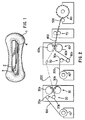
- Fig. 1 shows a multiple layer design having a bottom-most layer 1, a top fluid intake layer 2, a fluid distribution layer 3 disposed below the fluid intake layer 2, and an intermediate layer 4 disposed between the fluid distribution layer 3 and the bottom-most layer 1.
- the fluid intake layer is the layer closest to a wearer and has a low density ranging from about 0.02 - 0.06 g/cc and a basis weight from about 25 gsm to about 125 gsm. This results in pore sizes ranging from 80 microns to 1000 microns in diameter which are well suited to intake viscous menses fluid.
- the top or intake layer can be produced with a range of technologies. Nonexclusive examples include 100 weight percent synthetic fibers in a bonded carded web or an airlaid mixture of cellulosic and synthetic binder fibers.
- the layer below the top layer is designed to distribute and retain fluid and, as such, is called the distribution layer or strip. It has a density range from about 0.1 g/cc to about 0.2 g/cc but must be a higher density than the intake layer. This increased density is believed to help desorb the intake layer into the distribution layer.
- the distribution layer should have a basis weight from about 175 gsm to about 300 gsm and have an average pore size of about 40-500 microns in diameter.
- Materials suitable for this layer include airlaid materials that blend high levels of cellulosic fibers (80-95 weight percent) with synthetic binder fibers (5-20 weight percent) which stabilize the web performing this distribution function, provided, however, that the fibers that make up this layer are highly wettable.
- the bottom or pad shaping layer has a lower density than the distribution layer. Its primary function is to facilitate body fit, provide comfort to the wearer, and to provide additional coverage. Its density ranges from about 0.03 g/cc to about 0.10 g/cc so that it does not readily desorb the distribution layer resulting in most fluid remaining in the distribution layer.
- the pad shaping layer can be an airlaid web with 80-90 weight percent cellulosic pulp fluff blended with 10-20 weight percent synthetic binder fiber. While its primary purpose is pad shaping, this layer can accept liquid from the distribution strip, particularly when the distribution strip is highly loaded with liquid.
- layers are meant to also include a single monolithic material wherein the properties vary within it in such a manner as to satisfy the functional and physical characteristics of this invention.
- a material produced in a single step process and having, for example, characteristics varying from top to bottom regions in such a way as to satisfy the requirements of the invention is contemplated to be within the claims.
- intermediate layer 4 Disposed between the fluid intake/distribution layers 2, 3 and the pad layer 1 is intermediate layer 4 which acts to delay fluid transfer from the fluid intake/distribution layer 2, 3, and is hereinafter referred to as a fluid transfer delay layer.
- fluid intake layer 2 provides the fluid intake function while fluid distribution layer 3 is a higher density distribution strip.
- Fluid transfer delay layer 4 has a lower density than the fluid distribution layer 3, thereby providing a delay in fluid transfer to the wider and thicker pad shaping layer 1 which also provides comfort and thickness requirements.
- the center filling platform for personal care absorbent products in accordance with one embodiment of this invention uses an airlaid component to desorb the cover material and hold the majority of fluid therein.
- the pad layer of this type of product is a thick maxipad having a 600 gsm fluff pad and a 600 gsm fluff insert. Because this fluff material has to be present in the product for aesthetic and pad shaping reasons, it is ideal to utilize the capacity in that fluff.
- the transfer delay material layer currently in use in such products allows transfer of the fluid from the fluid intake/distribution layer at about an 80% saturation level of the distribution layer.
- the fluid transfer delay layer for personal care absorbent products in accordance with this invention is designed to promote the transfer of fluid from the fluid intake/distribution layer(s) to the pad layer while still allowing fluid distribution by the fluid intake/distribution layer along the machine direction of the article. This results in saturation levels of less than about 0.34 g/g/cm (0.86 g/g/in) of fluid in the intake/distribution layer(s) and/or greater than 0.024 g/g/cm (0.06g/g/in.) of fluid in the pad layer.
- Delay of fluid transfer in the personal care absorbent products of this invention is achievable by controlling the density of the transfer delay material such that it has a lower density than the layer below it. While material density is one way to cause the transfer of fluid to be delayed to the lower layer, other material attributes can also cause delay of fluid transfer. Other material candidates that are effective at causing delay include nonwovens such as spunbond, conjugate spunbond, or bonded carded webs. Apertured films can also be used to supply this function in an absorbent system.
- the fluid transfer delay layer forms an open area.
- open area can be provided by any number of techniques known to those skilled in the art including aperturing of the fluid transfer delay layer, slitting of the fluid transfer delay layer, and/or cutting of the fluid transfer delay layer. These open areas may be discrete windows cut into the ends of the transfer delay layer, or they may be uniform aperturing or brick slitting of the material. In addition, the open areas may be zoned such as by zone aperturing on the ends of the transfer delay layer.
- the transfer delay layer may be cut into a shape so that it is zoned in regions, for example, diamond shaped, where the transfer delay layer is as wide as the fluid intake/distribution layer in the centralized insult zone but then tapers in width to a point under the ends of the fluid intake/distribution layer.
- the transfer delay layer includes a wettability gradient where the center of the transfer delay layer beneath the centralized fluid intake zone is non-wettable or less wettable than the ends of the transfer delay layer.
- the fluid transfer delay layer comprises a nonwoven web having a basis weight in the range of about 0.5 osy (17 gsm) to about 1.0 osy (34 gsm) and comprises polyolefin fibers having a denier in the range of about 2.0 to about 3.0.
- the nonwoven web is a spunbond. Any wettable agents known to those skilled in the art may be employed in connection with the material of this invention.
- Spunbond fabrics described in Example 3 were produced using 96 weight % of E5D47 polypropylene (Union Carbide) and approximately 4% additive SCC(25950 #7 Rose). The fiber density for all webs in the Examples was approximately 0.91 g/cc.
- the thickness of the spunbond fabrics for the preceding specimens were aproximately 0.15 mm (0.006 inches) for the 13.6 gsm (0.4 osy) specimens and approximately 0.25 mm (0.010 inches) for the 20.3 (0.6) and 27.1 gsm (0.8 osy) specimens.
- Aperturing of Specimen E was carried out in accordance with the process shown in Fig. 2.
- the films were apertured mechanically in nip 30.
- the aperturing process comprises controlling the feed rate of the film 100 separate from the aperturing rate.
- the feed and the aperturing rate are controlled by the drive system 20.
- the aperturing rate is controlled by the rotation rate of the rolls in the aperturing nip 30, pattern roll 30a and anvil roll 30b.
- the speed of the film 100 is slower than the peripheral speed of pattern roll 30a and faster than the peripheral speed of anvil roll 30b.
- Film 100 is apertured under tension to minimize wrinkling of the film from a driven unwind 10 slower than the speed that drive system 20 and idler rolls (not shown) pull the film 100.
- the drive unit comprises "S" wrapping the film 100 between a driven rubber roll 20a and a steel roll 20b to control the entrance speed of the film into aperturing nip 30.
- Pattern roll 30a and anvil roll 30b contact one another and form nip 30 therebetween.
- Pattern roll 30a and anvil roll 30b rotate in opposite directions.
- Peripheral speed of pattern roll 30a is set at about 1.3-1.4 times the peripheral speed of anvil roll 30b.
- film 100 was apertured at a speed of 30.5 m (100 feet) per minute.
- pattern roll 30a and anvil roll 30b was made from stainless steel and had an outside diameter of about 61 cm (24 inches). The rolls were maintained at different temperatures using an internal hot oil system, pattern roll 30a being maintained at a temperature of about 124°C (255°F) and anvil roll 30b being maintained at a temperature of about 109°C (228°F).
- Anvil roll 30b had a smooth finish while pattern roll 30a had a plurality of pins positioned to give a desired pattern.
- the desired pattern had a density of about 93.5 pins per square centimeter (580-603 pins/inches 2 ) and a total contact area of about 37-46%.
- Each pin had a height of about 0.48 millimeters (0.01-0.022 inches), was tapered about 10°, and was circular in cross section. Because the pins had an apex diameter of about 0.73 millimeters (0.0286 inches), the surface area of the apex was about 0.40 millimeters 2 (0.00066 inches 2 ).
- film 100 As film 100 enters nip 30, it is apertured through the application of heat, shear and pressure by penetrating pins which extend completely through the thickness of film 100. Shear is created by running the pattern roll 30a faster than the anvil roll 30b. The apertured film 200 exits nip 30 under tension and can be directed around an idler roll (not shown) to keep the apertured film 200 from wrinkling as it is separated from pattern roll 30a. These process conditions produce an apertured film having an open area of approximately 28% with an equivalent-circular diameter (ECD) of approximately 600 microns.
- ECD equivalent-circular diameter
- the intake/distribution layer was a 200 gsm, 0.12g/cc airlaid with 90% Coosa 0054 pulp and 10% Hoechst-Celanese T-255 conjugate binder fiber while the pad layer was composed of 600 gsm Coosa 0056 pulp with a density of 0.09 g/cc using a Sine Wave Embossed Pattern #C200-M-3558C.
- the cover was a 0.028 mm (1.1 mil) low density polyethylene film (XP3134A-Edison Plastics, Newport News, Virginia) apertured using the process previously described.
- This apertured film was point bonded to a 6 dpf, 23.7 gsm (0.7 osy) Chisso through air bonded carded web which had a density of approximately 0.018 g/cc.
- the Chisso fibers available from Chisso Corporation, had a surfactant treatment consisting of a wettable finish, HR6.
- This apertured film and bonded carded web composite cover are also known as QUEST.
- Table 3 below shows intake time comparisons of different transfer delay layers when menses simulant is used as the test fluid.
- the results shown in Table 3 were generated using the intake/rewet test (STP 682-W) with 4 ml of menses simulant.
- Table 3 Sample Intake Time Specimen C 29.57 Control 39.95 Specimen A 27.12 Specimen D 43.21 Specimen B 28.93 Specimen E 38.74
- Table 4 shows the effects of different transfer delay layers on rewet values when using menses simulant as the test fluid.
- Table 4 Sample Rewet (g) Specimen C 0.18 Control 0.88 Specimen A 0.29 Specimen D 0.70 Specimen B 0.17 Specimen E 0.50 The results show that the 27.1 gsm (0.8 osy) treated spunbond or a 13.6 gsm (0.4 osy) spunbond results in rewet values that are comparable to a code without a TDL.
- the apertured film code and the 20.3 gsm (0.6 osy) TDL reduce rewet beyond the 27.1 gsm (0.8 osy) control code.
- the results were generated using the intake/rewet test (STP 682-W) with 4 ml of menses simulant.
- Table 5 below shows how stain length (and therefore distribution) and fluid paritioning in the intake/distribution layer and the pad layer can be modified by imparting wettability to the transfer delay layer or reducing its basis weight.
- the data below was generated with the flat system fluid distribution test using 6 ml of menses simulant and 1725 Pa (0.25 psi.)
- increasing the wettability or decreasing the basis weight of the transfer delay layer decreases the amount of fluid in the intake/distribution layer and increases the amount of fluid in the pad layer.
- the stain length in the intake distribution layer decreases with increases in wettability or decreases in basis weight of the transfer delay material.
- the other important characteristic of the material is the permeability.
- the permeabilities have been measured and ⁇ P/ ⁇ calculated from experimental measurements to define the important characteristics of this invention.
- transfer delay materials with permeability essentially equal to or greater than about 500 darcies or ⁇ P/ ⁇ essentially equal to or greater than 0.0010 produce the intended results.
Abstract
Description
- This invention relates to absorbent articles, particularly absorbent structures which are useful in personal care products such as disposable sanitary napkins, diapers, incontinence garments, and the like. More particularly, this invention relates to absorbent systems that must manage complex viscous body fluids such as menses.
- Absorbent articles such as feminine pads or sanitary napkins, diapers and incontinence garments are intended to intake and retain body fluids. Desired performance objectives of these articles include low leakage from the product and a dry feel to the wearer. Currently available products suffer from higher than desired leakage levels, producing stains on clothing, and are not perceived by users to fully deliver on other consumer attributes such as dryness, fit, comfort and continence. Leakage can occur due to a variety of shortcomings in the product, not the least of which is an insufficient rate of fluid uptake by the absorbent system, particularly on the second or third liquid surges. This is particularly problematic with feminine care products intended for overnight use where high loadings are often incurred requiring significant fluid retention capacity in order to hold the majority of the fluid.
- Most commercially available sanitary pads have relatively high leakage rates, failing as much as 30% of the time. Such failures are believed to be due to the highly viscous nature of menses and the great variability in delivery volume which results in overloading of the pad in the target area and subsequent leaking. Insufficient distribution of menses is believed to be one of the key causes of the target area overloading.
- In the field of urine management in personal care products like diapers, distribution is often provided by materials that have small pores with a narrow pore size distribution. These materials must move the high volume, low viscosity urine insults out of the target area in a time sufficient for the target area to be able to accept the next insult. The movement of urine may be to relatively remote parts of the diaper, overcoming substantial hydrostatic pressure. In contrast thereto, feminine hygiene products experience lower total insult volumes, but the fluid is of greater viscosity, making it more difficult to move the fluid. Distribution materials must be quite different for feminine hygiene products than for products concerned primarily with urine management.
- Absorbent articles have typically employed various types of absorbent pads composed of cellulosic fibers. Particular absorbent garments may configure to control the distribution of absorbed liquids. For example, an absorbent article can have a liquid permeable transport layer which is located between a top sheet layer and an absorbent body. In other configurations, a conventional absorbent member can have fluid storage and acquisition zones composed of cellulosic fluff mixed with absorbent gelling particles and may include a dual-layer absorbent core arrangement comprising a bottom fluff pad containing hydrogel particles, and a top fluff pad with little or no hydrogel particles.
- Non-woven materials such as carded webs and spunbond webs have been used as the body side liners in absorbent products. Specifically, very open, porous liner structures have been employed to allow liquid to pass through them rapidly and help keep the body skin separated from the wetted absorbent pad beneath the liner. Some structures have incorporated zoned surfactant treatments in preselected areas of the liners to increase the wettability of the preselected regions and thereby control the amount of liquid wet-back onto a wearer's skin. In addition, other layers of material, such as those constructed with thick, lofty fabric structures, have been interposed between the liner and absorbent pad for the purpose of reducing wet-back.
- With conventional fluff-based absorbent structures, such as those discussed above, the cellulosic fibers, when wetted, can lose resiliency and collapse. As a result, the liquid uptake rate of the wetted structures may become too low to adequately accommodate subsequent, successive liquid surges. Where absorbent gelling particles are incorporated between the fibers to hold them apart, the gelling particles swell and do not release the absorbed fluid. Swelling of the particles can then diminish the void volume of the absorbent structure and reduce the ability of the structure to rapidly uptake fluids.
- The addition of more absorbent material, such as secondary fluff pledgets, or absorbent gelling particles, has been employed to increase holding capacity. The desired rate of liquid intake within such arrangements, however, may not be sufficiently sustained during successive liquid surges.
- Despite the development of absorbent structures as discussed hereinabove, there remains a need for improved absorbent structures which can adequately reduce the incidence of leakage from absorbent products, such as feminine hygiene products. There is a need for an absorbent structure which can provide improved handling of liquid surges and more effectively uptake and retain repeated loadings of liquid during use.
- Accordingly, it is one object of this invention to provide a feminine hygiene product having superior distribution and transfer performance to allow movement of menses from a target area and provide comfort, dry feeling, and lower leakage than traditional such products.
- It is another object of this invention to provide an overnight use feminine hygiene product having the capacity to hold the majority of fluids resulting from the high loadings which have been observed in such overnight products.
- The overnight feminine hygiene products typically are thick maxipads with a 600 gsm basis weight fluff pad and fluff insert, which fluff material is present in the product for aesthetic and pad shaping reasons. It is one object of this invention to provide an absorbent system which enables utilization of the potential fluid storage capacity in the fluff.
- It is yet another object of this invention to provide a feminine hygiene product such as an Ultrathin, Maxi, Overnite, Curved, Securehold and the like which provides good distribution and fluid transfer thus promoting absorbency and dryness.
- These and other objects of this invention are achieved by a personal care absorbent article comprising a fluid intake/distribution layer, a fluid transfer delay layer disposed beneath the fluid intake/distribution layer, which fluid transfer delay layer enables fluid transfer from the fluid intake/distribution layer resulting in a fluid saturation of less than about 0.34 g/g/cm (0.86 g/g/in) in the fluid intake/distribution layer, and a pad layer disposed beneath the fluid transfer delay layer having a fluid saturation level essentially equivalent to or greater than 0.024 g/g/cm (0.06 g/g/inch) wherein the permeability of said fluid transfer delay layer is greater than 493x10-8 cm2 (500 darcies) and the capillarity (ΔP/γ) of said fluid transfer delay layer is greater than or equal to 0·0010 microns-1. The fluid intake/distribution layer is comprised of stabilized, highly wettable fibers arranged to provide capillary pore sizes and a degree of wettability ideally suited to wick visco-elastic fluids, which layer, when exposed to visco-elastic fluids and simulants, demonstrates improved fluid distribution performance in terms of the distance wicked, the wicking rate, as well as the amount of fluid moved. The fluid intake/distribution layer comprises a class of distribution materials composed of stabilized, highly wettable fibers arranged to provide capillary pore sizes and a degree of wettability ideally suited to wick visco-elastic fluids. Stabilization may be accomplished by the use of liquid binders, binder fibers, thermally, or in any other method known to those skilled in the art. When exposed to a visco-elastic fluid or fluid simulant, these materials demonstrate improved fluid distribution performance for distance wicked, wicking rate and amount of fluid moved. The pore characteristics are stable, whether dry or wet, with minimal, preferably less than about 25%, more particularly 20%, and still more particularly 15%, swelling or collapse when wetted with the visco-elastic fluid simulant. All of these properties are critical to the overall performance of distribution materials placed in the target area of personal care products such as feminine hygiene products.
- Current fluid transfer delay layers employed in personal care absorbent articles allow transfer of fluid from the fluid intake/distribution layer to the pad layer resulting in fluid saturation levels of essentially 0.34 g/g/cm (0.86/g/g/in) in the intake distribution layer and/or fluid saturation levels of 0.026 g/g/cm (0.067g/g/in) the pad layer. Personal care articles which demonstrate relatively high levels of saturation in the intake/distribution layer and relatively low levels of saturation in the pad layer as measured using the flat system testing procedure often have relatively high intake times and high rewet values such as those measured with the intake/rewet test. The fluid transfer delay layer employed in the personal care absorbent article of this invention enables fluid transfer from the intake/distribution layer to the pad layer while still allowing fluid distribution by the fluid intake/distribution layer along the machine direction of the article. This results in a fluid saturation level of less than or equal to about 0.86 g/g/in in the fluid intake/distribution material and/or a fluid saturation level essentially equal to or greater than 0.06 g/g/in in the pad layer. Fluid transfer delay is generally accomplished by the fluid transfer delay layer having a lower density than the fluid intake/distribution layer.
- These and other objects and features of this invention will be better understood from the following detailed description taken in conjunction with the drawings wherein:
- Fig. 1 is a diagram showing a multiple-layered personal care absorbent article in accordance with one embodiment of this invention; and
- Fig. 2 is a schematic diagram showing a process for aperturing a film material for use in a fluid absorbent material in accordance with one embodiment of this invention.
- As used herein, the following terms have the definitions ascribed to them.
- The term "disposable" includes being disposed of after use and not intended to be washed and reused.
- The term "hydrophilic" describes fibers or the surfaces of fibers which are wetted by aqueous liquids in contact with the fibers. The degree of wetting of the materials can, in turn, be described in terms of the contact angles and the surface tensions of the liquids and materials involved. Equipment and techniques suitable for measuring the wettability of particular fiber materials can be provided by a CAHN SFA-222 Surface Force Analyzer System, or a substantially equivalent system. When measured with this system, fibers having contact angles less than 90° are designated "wettable" or hydrophilic, while fibers having contact angles equal to or greater than 90° are designated "non-wettable" or hydrophobic.
- As used herein, the term "nonwoven fabric or web" means a web having a structure of individual fibers or threads which are interlaid, but not in an identifiable manner, as in a knitted fabric. Nonwoven fabrics or webs have been formed from many processes such as, for example, meltblowing processes, spunbonding processes, and bonded carded web processes. The basis weight of nonwoven fabrics is usually expressed in ounces of material per square yard (osy) or grams per square meter (gsm) and the fiber diameters useful are usually expressed in microns. (Note that to convert from osy to gsm, multiply osy by 33.91).
- As used herein, the term "spunbonded fibers" refers to small diameter fibers which are formed by extruding molten thermoplastic material as filaments from a plurality of fine, usually circular capillaries of a spinneret with the diameter of the extruded filaments then being rapidly reduced as by, for example, in U.S. Patent 4,340,563 to Appel et al., U.S. Patent 3,692,618 to Dorschner et al., U.S. Patent 3,802,817 to Matsuki et al., U.S. Patent 3,338,992 and U.S. Patent 3,341,394 to Kinney, U.S. Patent 3,502,763 to Hartmann, and U.S. Patent 3,542,615 to Dobo et al. Spunbond fibers are generally not tacky when they are deposited onto a collecting surface. Spunbond fibers are generally continuous and have average diameters (from a sample of at least 10) larger than 7 microns, more particularly, between about 10 and 20 microns. The fibers may also have shapes such as those described in U.S. Patent 5,277,976 to Hogle et al., U.S. Patent 5,466,410 to Hills, and U.S. Patent 5,069,970 and U.S. Patent 5,057,368 to Largman et al., which describe hybrids with unconventional shapes.
- As used herein, the term "meltblown fibers" means fibers formed by extruding a molten thermoplastic material through a plurality of fine, usually circular, die capillaries as molten threads or filaments into converging high velocity, usually hot, gas (for example, air) streams which attenuate the filaments of molten thermoplastic material to reduce their diameter, which may be to microfiber diameter. Thereafter, the meltblown fibers are carried by the high velocity gas stream and are deposited on a collecting surface to form a web of randomly dispersed meltblown fibers. Such a process is disclosed, for example, in U.S. Patent 3,849,241 to Butin et al. Meltblown fibers are microfibers which may be continuous or discontinuous, are generally smaller than 10 microns in average diameter, and are generally tacky when deposited onto a collecting surface.
- As used herein, the term "polymer" generally includes, but is not limited to, homopolymers, copolymers, such as for example, block, graft, random and alternating copolymers, terpolymers, etc., and blends and modifications thereof. Furthermore, unless otherwise specifically limited, the term "polymer" shall include all possible geometric configurations of the molecule. These configurations include, but are not limited to, isotactic, syndiotactic and random symmetries.
- As used herein, the term "machine direction" or "MD" means the length of a fabric in the direction in which it is produced. The term "cross machine direction" or "CD" means the width of fabric, that is a direction generally perpendicular to the MD.
- As used herein, the term "monocomponent" fiber refers to a fiber formed from one or more extruders using only one polymer. This is not meant to exclude fibers formed from one polymer to which small amounts of additives have been added for coloration, anti-static properties, lubrication, hydrophilicity, etc. These additives, for example titanium dioxide for coloration, are generally present in an amount less than about 5 weight percent and more typically about 2 weight percent.
- As used herein, the term "conjugate fibers" refers to fibers which have been formed from at least two polymers extruded from separate extruders but spun together to form one fiber. Conjugate fibers are also sometimes referred to as multicomponent or bicomponent fibers. The polymers are usually different from each other though conjugate fibers may be monocomponent fibers. The polymers are arranged in substantially constantly positioned distinct zones across the cross-section of the conjugate fibers and extend continuously along the length of the conjugate fibers. The configuration of such a conjugate fiber may be, for example, a sheath/core arrangement wherein one polymer is surrounded by another, or may be a side-by-side arrangement, a pie arrangement, or an "islands-in-the-sea" arrangement. Conjugate fibers are taught by U.S. Patent 5,108,820 to Kaneko et al., U.S. Patent 4,795,668 to Krueger et al., U.S. Patent 5,540,992 to Marcher et al., and U.S. Patent 5,336,552 to Strack et al. Conjugate fibers are also taught by U.S. Patent 5,382,400 to Pike et al., and may be used to produce crimp in the fibers by using the differential rates of expansion and-contraction of the two (or more) polymers. Crimped fibers may also be produced by mechanical means and by the process of German Patent DE 2513251A1. For two component fibers, the polymers may be present in ratios of 75/25, 50/50, 25/75 or any other desired ratios. The fibers may also have shapes such as those described in U.S. Patent 5,277,976 to Hogle et al., U.S. Patent 5,466,410 to Hills and U.S. Patent 5,069,970 and U.S. Patent 5,057,368 to Largman et al., which describe fibers with unconventional shapes.
- As used herein, the term "biconstituent fibers" refers to fibers which have been formed from at least two polymers extruded from the same extruder as a blend. Biconstituent fibers do not have the various polymer components arranged in relatively constantly positioned distinct zones across the cross-sectional area of the fiber and the various polymers are usually not continuous along the entire length of the fiber, but rather typically form fibrils or protofibrils which start and end at random. Biconstituent fibers are sometimes also referred to as multiconstituent fibers. Fibers of this general type are taught, for example, by U.S. Patents 5,108,827 and 5,294,482 to Gessner.
- As used herein, the term "bonded carded web" refers to webs made from staple fibers which are sent through a combing or carding unit, which breaks apart and aligns the staple fibers in the machine direction to form a generally machine direction-oriented fibrous nonwoven web. Such fibers are usually purchased in bales which are placed in a picker which separates the fibers prior to the carding unit. Once the web is formed, it is then bonded by one or more of several known bonding methods. One such bonding method is powder bonding, wherein a powdered adhesive is distributed through the web and then activated, usually by heating the web and adhesive with hot air. Another suitable bonding method is pattern bonding, wherein heated calender rolls or ultrasonic bonding equipment are used to bond the fibers together, usually in a localized bond pattern, though the web can be bonded across its entire surface, if so desired. Another suitable and well-known bonding method, particularly when using bicomponent staple fibers, is through-air bonding.
- As used herein, the term "airlaying" means a process by which a fibrous nonwoven layer can be formed. In the airlaying process, bundles of small fibers having typical lengths ranging from about 6 to about 19 mm are separated and entrained in an air supply and then deposited onto a forming screen, usually with the assistance of a vacuum supply. The randomly deposited fibers then are bonded to one another using, for example, hot air or a spray adhesive.
- As used herein, the term "personal care product" or "personal care absorbent product" means diapers, training pants, absorbent underpants, adult incontinence products, bandages and feminine hygiene products.
- A sample strip of material approximately one inch (2.5 cm) by eight inches (20 cm) is placed horizontally such that when the sample strip is positioned in a liquid reservoir at the beginning of the test, the sample strip will just touch the liquid surface. The relative humidity is maintained at about 90% to about 98% during the evaluation. The sample strip is placed next to a large (effectively infinite) amount of liquid and a stopwatch started as soon as the edge of the sample strip touches a surface of the solution. The horizontal distance of the liquid front traveling along the sample strip and the liquid weight absorbed by the sample strip at various times are recorded. The weight of the liquid absorbed by the sample strip from the beginning of the evaluation to about a half inch (1.3 cm), one inch, two inches (5 cm) and three inches (7.6 cm) is also determined from the data. The liquid used in this testing is a fluid designed to simulate the visco-elastic and other properties of menses and is made according to a procedure discussed hereinbelow.
- This test is used to determine the intake time of a known quantity of fluid into a material and/or material system. The test apparatus consists of a rate block, a funnel and a timer or stopwatch.
- For measuring fluid intake time, a material system is assembled as it would be in finished product form according to finished product dimensions:
Cover - (QUEST) 7.5 cm x 15 cm (3" x 6") Intake/Distribution layer (200gsm, 0.12g/cc airlaid) 3.75 cm x 15 cm (1.5" x 6") Transfer delay layer 7.5 cm x 15 cm (3" x 6") Pad layer (fluff or airlaid) 7.5 cm x 15 cm (3" x 6") - The rewet portion of this test is used to determine the amount of fluid that will return to the surface of a cover when a load is applied. The amount of fluid that comes back through the surface is called the rewet value. The more fluid that returns to the surface, the larger the rewet value, while the smaller the amount of fluid that returns to the surface, the lower the rewet value. Lower rewet values are associated with a dryer material and hence a dryer product. In considering rewet, three properties are important:
- intake - if the material/system does not have good intake, then fluid can rewet;
- ability of an absorbent to hold fluid - the more the absorbent holds onto the fluid, the less fluid is available for rewet; and
- flowback - the more the cover prohibits fluid from coming back through the cover, the lower the rewet.
- After the system is insulted during the intake portion, it is allowed to interact with the system for 1 minute as the rate block rests on top of the materials. The material system is placed onto a closed bag, partially filled with saline solution. The fluid back is positioned on top of a lab jack. Pieces of blotter paper are weighed and placed on top of the material system. The bag with the material system is raised against a fixed acrylic plate using the lab jack until a total of 609 KPa (1 psi) is applied. The pressure is held fixed for 3 minutes after which the pressure is removed and the blotter paper is weighed. The blotter-paper should retain any fluid that is transferred to it from the cover/absorbent system. The difference in weight between the original blotter and the blotter after the absorption experiment is the rewet value. The individual material components are then weighed to determine fluid partitioning after the pressure is applied.
- The purpose of this procedure is to determine the fluid handling characteristics of various absorbent systems through analysis of stain length, saturation capacity, and the fluid loading of the system components. The equipment required includes hourglass-shaped acrylic plates (with a 0.625 cm (0.25 inch) hole in the center) weighing approximately 330 grams, syringes, 0.3 cm (one-eighth inch) I.D. Tygon tubing, pipette pump, menses simulant, and a laboratory balance (accurate to 0.00g).
- Samples to be tested are cut to a desired shape (currently 3.8 cm by 14 cm (1.5 inches by 5.5 inches) for fluid intake/distribution layers, 4.4 cm by 14 cm (1.75 inches by 5.5 inches) for transfer delay layers, and 200 mm long hourglass shape for pad layers). The 14 cm (5.5 inch) layers are marked into 2.8 cm (1.1 inch) sections and the pad layer is marked into sections corresponding to the marks on the 14 cm (5.5 inch) layers when they are centered on the pad layer. Each component is weighed and the weight recorded. The individual components are assembled into a desired component system maintaining the marked sections aligned and one end is labeled as the top. Syringes are filled with menses simulant and Tygon tubing attached to the syringes. The syringes are placed in a pipette pump which is programmed to deliver a given amount of simulant, currently 30 cc syringes dispensing 10 ml of simulant in one hour. With the open ends of the tubing placed in a beaker, the tubing is primed by running the pump until all air is out of the tubing and simulant is exiting the tubing at the insult end. The component systems to be tested are placed near the pipette pump and a 5 cm (two inch) by 15 cm (six inch) piece of 25 gsm, 10d BCW is placed on top of the center of the system over which an acrylic plate is placed, also centered on top of the system. The free end of one tubing is inserted into the hole in the acrylic plate and the pipette pump started to begin the insults. At the end of the insult period, the tubing and acrylic plates are removed. The BCW is then carefully removed without moving the underlying layers and discarded. Each layer is then individually weighed and the weight recorded. Then, beginning at the end labeled as the top, each marked section is cut and weighed. The stain length for each layer is measured and recorded and the data entered into a spreadsheet for graphing and analysis. The fluid loading (g/g) is calculated by dividing the amount of fluid absorbed in a material by the dry weight of the material. The fluid saturation is calculated by dividing the fluid loading by the stain length.
- The artificial menses fluid used in the testing was made from blood and egg white by separating the blood into plasma and red cells and separating the white into thick and thin portions, where "thick" means it has a viscosity after homogenization above about 0.02 Pa.s (20 centipoise)at 150 sec-1, combining the thick egg white with the plasma and thoroughly mixing, and finally adding the red cells and again thoroughly mixing.
- Blood, in this case defibrinated swine blood, was separated by centrifugation at 3000 rpm for thirty minutes, although other methods or speeds and times may be used if effective. The plasma was separated and stored separately, the buffy coat removed and discarded, and the packed red blood cells stored separately as well.
- Eggs, in this case jumbo chicken eggs, were separated, the yolk and chalazae discarded and the egg white retained. The egg white was separated into thick and thin portions by straining the white through a 1000 micron nylon mesh for about three minutes, and the thinner portion discarded. Note that alternative mesh sizes may be used and the timer method may be varied provided the viscosity is at least that required. The thick portion of egg white which was retained on the mesh was collected and drawn into a 60 cc syringe which was then placed on a programmable syringe pump and homogenized by expelling and refilling the contents five times. In this case, the amount of homogenization was controlled by the syringe pump rate of about 100 ml/min, and the tubing inside diameter of about 0.3 cm (0.12 inches). After homogenizing, the thick egg whites had a viscosity of at least 0.02 Pa.s (20 centipoise) at 150 sec-1 and were then placed in the centrifuge and spun to remove debris and air bubbles at about 3000 rpm for about 10 minutes, although any effective method to remove debris and bubbles may be used.
- After centrifuging, the thick, homogenized egg white, which contains ovamucin, was added to a 300cc FENWAL® Transfer Pack using a syringe. 60cc of the swine plasma were then added to the Transfer Pack which was clamped, all air bubbles removed, and placed in a Stomacher lab blender where it was blended at normal (or medium) speed for about two minutes. The Transfer Pack was then removed from the blender, 60cc of swine red blood cells added, and the contents mixed by hand kneaded for about two minutes or until the contents appeared homogenous. A hematocrit of the final mixture shows a red blood cell content of about 30 weight percent and generally should be at least within a range of 28-32 weight percent for artificial menses made according to this example. The amount of egg white is about 40 weight percent.
- The ingredients and equipment used in the preparation of artificial menses are readily available. Below is a listing of sources for the items used in the example, though of course other sources may be used provided they are approximately equivalent.
- Blood (swine): Cocalico Biologicals, Inc., 449 Stevens Rd., Reamstown, Pennsylvania 17567, (717) 336-1990.
- Fenwal® Transfer pack container, 300 ml, with coupler, code 4R2014: Baxter Healthcare Corporation, Fenwal Division, Deerfield, Illinois 60015.
- Harvard Apparatus Programmable Syringe Pump Model No. 55-4143: Harvard Apparatus, South Natick, Massachusetts 01760.
-
Stomacher 400 laboratory blender Model No. BA 7021, Serial No. 31968: Seward Medical, London, England, United Kingdom. - 1000 micron mesh, Item No. CMN-1000-B: Small Parts, Inc., PO Box 4650, Miami Lakes, Florida 33014-0650, 1-800-220-4242.
- Hemata Stat-II device to measure hemocrits, Serial No. 1194Z03127: Separation Technology, Inc., 1096 Rainer Drive, Altamont Springs, Florida 32714.
- Static contact angle measurements were conducted using artificial menses on film surfaces. These surfaces were either treated or unmodified as described in this work. Drops which measured 0.5 to 2 mm in height were applied to the surface of the film with a tapered tip using a syringe and a programmable pump (Harvard Apparatus PHD 2000). A Leica Wild M3Z stereoscopic microscope was tilted on edge to view the drop of fluid as it was applied to the film surface. A Sony DKC-5000 digital photocamera 3CCD recorded the application of the fluid to the surface. Later, contact angle (θ) measurements were made on the individual drops of fluid as they contacted the surface using an image analysis program. Five measurements of contact angle were made on each side of the drop and averaged. A total of five to ten drops were measured for each film and averaged.
- A pore radius distribution chart shows pore radius in microns in the x-axis and pore volume (volume absorbed in cc of liquid/gram of dry sample at that pore interval) in the y-axis. The peak pore size (rpeak) was extracted from this chart by measuring the value of pore radius at the largest value of volume absorbed from the distribution of pore volume (cc/g) vs. pore radius. This distribution is determined by using an apparatus based on the porous plate method first reported by Burgeni and Kapur in the Textile Research Journal Volume 37, 356-366 (1967). The system is a modified version of the porous plate method and consists of a movable Velmex stage interfaced with a programmable stepper motor and an electronic balance controlled by a computer. A control program automatically moves the stage to the desired height, collects data at a specified sampling rate until equilibrium is reached, and then moves to the next calculated height. Controllable parameters of the method include sampling rates, criteria for equilibrium and the number of absorption/desorption cycles.
- Data for this analysis was collected using mineral oil (Peneteck Technical Mineral Oil) with a viscosity of 0.006 Pa.s (6 centipoise) manufactured by Penreco of Los Angeles, California in desorption mode. That is, the material was saturated at zero height and the porous plate (and the effective capillary tension on the sample) was progressively raised in discrete steps corresponding to the desired capillary radius. The amount of liquid pulled out from the sample was monitored. Readings at each height were taken every fifteen seconds and equilibrium was assumed to be reached when the average change of four consecutive readings was less than 0.005 g. This method is described in more detail in U.S. Patent 5,679,042 to Varona.
- The caliper of a material is a measure of thickness and is measured at 345 Pa (0.05 psi) with a Starret-type bulk tester, in units of millimeters or centimetres (inches). The foot of the bulk tester used in these studies is a small acrylic cylinder measuring 7.5 cm (3") wide by 1.25 cm (0.5 inches) in thickness.
- Permeability is obtained from a measurement of the resistance by the material to the flow of liquid. A liquid of known viscosity is forced through the material of a given thickness at a constant flow rate and the resistance to flow, measured as a pressure drop is monitored. Darcy's Law is used to determine permeability as follows:

permeability: cm2 or darcy 1 darcy = 9.87 x 109 cm2 flow rate: cm/sec viscosity: pascal-sec pressure drop: pascals - The apparatus consists of an arrangement wherein a piston within a cylinder pushes liquid through the sample to be measured. The sample is clamped between two aluminum cylinders with the cylinders oriented vertically. Both cylinders have an outside diameter of 8.9 cm (3.5"), an inside diameter of 6.3 cm (2.5") and a length of about 15 cm (6"). The 7.5 cm (3") diameter web sample is held in place by its outer edges and hence is completely contained within the apparatus. The bottom cylinder has a piston that is capable of moving vertically within the cylinder at a constant velocity and is connected to a pressure transducer that capable of monitoring the pressure of encountered by a column of liquid supported by the piston. The transducer is positioned to travel with the piston such that there is no additional pressure measured until the liquid column contacts the sample and is pushed through it. At this point, the additional pressure measured is due to the resistance of the material to liquid flow through it.
- The piston is moved by a slide assembly that is driven by a stepper motor. The test starts by moving the piston at a constant velocity until the liquid is pushed through the sample. The piston is then halted and the baseline pressure is noted. This corrects for sample buoyancy effects. The movement is then resumed for a time adequate to measure the new pressure. The difference between the two pressures is the pressure due to the resistance of the material to liquid flow and is the pressure drop used in Equation (1). The velocity of the piston is the flow rate. Any liquid whose viscosity is known can be used, although a liquid that wets the material is preferred since this ensures that saturated flow is achieved. The measurements disclosed herein were carried out using a piston velocity of 20 cm/min, mineral oil (Peneteck Technical Mineral Oil manufactured by Penreco of Los Angeles, California) of a viscosity of 6 centipoise.
- Alternatively, permeability can be calculated from the following equation:


- Conductance is calculated as permeability per unit thickness and gives measure of the openness of a particular structure and, thus, an indication of the relative ease at which a material will pass liquid. The units are darcies/mil (0.025 mm).
- This invention relates to personal care absorbent articles such as disposable sanitary napkins, diapers, incontinence garments, and the like which utilize a class of distribution materials composed of stabilized, highly wettable fibers arranged to provide capillary pore sizes and a degree of wettability ideally suited to wick visco-elastic fluids coupled with a transfer delay material having characteristics which enhance the performance of the distribution materials. Stabilization of the distribution materials may be accomplished by the use of liquid binders, binder fibers, thermally, or in any other method known to those skilled in the art. When exposed to a visco-elastic fluid or fluid simulant, the distribution materials demonstrate improved fluid distribution performance for distance wicked, wicking rate and amount of fluid moved. In addition, the fluid transfer delay materials enable the use of the thick pad layers present in certain of the absorbent articles for fluid storage by reducing the saturation level of the distribution materials at which fluid in the distribution materials is transported from the distribution materials into the thick pad layers. The pore characteristics of the distribution materials are stable, whether dry or wet with minimal, preferably less than about 25%, more particularly 20% and still more particularly 15%, swelling or collapsed-when wetted with the visco-elastic fluid simulant. All of these properties are critical to the overall performance of distribution materials placed in the target area of personal care absorbent articles such as feminine pads.
- Fluid distribution capability requires the appropriate capillary pore structure within a specified range of wettability for the fluid of interest. Distribution materials have been developed using several technology approaches that demonstrate the underlying material characteristics needed for favorable performance. Examples of such materials follow.
- In this example, the distribution material consists of about 80 weight percent fluff pulp (Rayonier R-9401 mercerized southern soft wood roll pulp) and about 20 weight percent Danaklon shortcut (5 mm) 2.2 denier polyethylene/polypropylene sheath/core conjugate binder fiber with an S2/B2/39 finish. This finish is advertised as remaining hydrophilic after repeated insults. The material is produced at three different densities: 0.05 g/cc, 0.1 g/cc and 0.2 g/cc at a basis weight of 100 to 250 gsm.
- The materials were tested according to the horizontal wicking test which was repeated for a total of three tests using 2.5 cm (one inch) by 20 cm (eight inch) samples. Table 1 shows the results where weight is given in grams of retained fluid, time in seconds, and "DNR" means "did not reach."
Table 1 Rep 1 Rep 2Rep 3 Cm (Inches) Wt.(g) Time(s) Wt.(g) Time(s) Wt.(g) Time(s) 0.05 g/cc 1.2 (0.5) 1.26 50 1.15 50 1.13 54 2.5 (1.0) 1.80 161 1.77 170 1.55 170 5.0 (2.0) 1.56 633 1.71 611 1.48 714 7.5 (3.0) 1.02 DNR 0.89 DNR 0.72 DNR 0.1 g/cc 1.2 (0.5) 0.86 20 0.68 24 0.76 18 2.5 (1.0) 1.14 155 1.07 123 1.03 139 5.0 (2.0) 0.95 811 0.91 868 0.9 810 7.5 (3.0) 0.32 DNR 0.16 DNR 0.23 DNR 0.2 g/cc 1.2 (0.5) 0.79 56 0.83 43 0.73 56 2.5 (1.0) 1.11 253 1.03 174 0.98 245 5.0 (2.0) 0.62 DNR 0.96 1074 0.76 DNR 0.21 DNR - The distribution material is produced by the Dan-Web airlaying process. However, any other satisfactory procedure known to those skilled in the art may be used to produce the material. Samples tested for pore volume distribution show that as density is lowered and pore size is increased, wicking performance is greatly improved.
- In this example, the distribution materials are bonded carded webs consisting of 100 weight percent eccentric sheath/core conjugate fibers of polyethylene and polypropylene available from the Chisso Chemical Company of Japan. The fibers have a finish known as HR6 applied to them. Table 2, hereinbelow, shows the wicking results for a 0.028 g/cc sample, a 0.068 g/cc sample and a 0.028 g/cc sample in which the fibers were oriented in the carding process. The distance is given in cm (inches), the weight in grams and the time in minutes and seconds as indicated. The results of pore volume distribution tests on this material show that when a high percentage of the pore volume has pores that range from about 200 to about 400 microns, better wicking results are achieved.
Table 2 Density Distance Weigh Time 0.028 g/cc 2.5 (1.0) 1.7 50 sec. 5.0 (2.0) 1.1 10 min. 7.5 (3.0) 0.9 17 min. 0.068 g/cc 2.5 (1.0) 0.6 1.5 min. 5.0 (2.0) 0.1 DNR 0.028 g/cc oriented 2.5 (1.0) 1.7 1 min. 5.0 (2.0) 1.2 6.6 min. 7.5 (3.0) 0.9 18 min. 10.0 (4.0) 0.1 20+ min. - The distribution material of this invention should wick the artificial menses fluid according to the horizontal wicking test a distance of an inch (2.5 cm) in less than about 1.5 minutes to be successful. Materials meeting this performance criteria generally have a pore size distribution with a high percentage (usually more than 50%, more particularly more than 60% and still more particularly more than 70%) of pore diameters between about 80 and 400 microns and a density below about 0.15 g/cc. It is believed that increasing the wettability of the pore surface results in greater wicking driving forces which can maintain liquid movement in smaller pores with higher resistive forces.
- Personal care absorbent articles of this invention have been designed to have controlled final liquid storage in a centralized region along the length of the pad. This functional behavior is highly desirable for preventing side leakage which is a dominant form of leakage for feminine pads. This storage behavior is achieved by a layered absorbent design that can include three or more layers. The bottom-most layer, that is, the layer furthest from a wearer, has larger x-y dimensions than the other layers that are on top of it. This creates a raised topography design that increases the probability that menses from the wearer will land on the narrow strip as shown in Fig. 1. Fig. 1 shows a multiple layer design having a bottom-most layer 1, a top
fluid intake layer 2, a fluid distribution layer 3 disposed below thefluid intake layer 2, and an intermediate layer 4 disposed between the fluid distribution layer 3 and the bottom-most layer 1. - The fluid intake layer is the layer closest to a wearer and has a low density ranging from about 0.02 - 0.06 g/cc and a basis weight from about 25 gsm to about 125 gsm. This results in pore sizes ranging from 80 microns to 1000 microns in diameter which are well suited to intake viscous menses fluid. The top or intake layer can be produced with a range of technologies. Nonexclusive examples include 100 weight percent synthetic fibers in a bonded carded web or an airlaid mixture of cellulosic and synthetic binder fibers.
- The layer below the top layer is designed to distribute and retain fluid and, as such, is called the distribution layer or strip. It has a density range from about 0.1 g/cc to about 0.2 g/cc but must be a higher density than the intake layer. This increased density is believed to help desorb the intake layer into the distribution layer. The distribution layer should have a basis weight from about 175 gsm to about 300 gsm and have an average pore size of about 40-500 microns in diameter. Materials suitable for this layer include airlaid materials that blend high levels of cellulosic fibers (80-95 weight percent) with synthetic binder fibers (5-20 weight percent) which stabilize the web performing this distribution function, provided, however, that the fibers that make up this layer are highly wettable. The bottom or pad shaping layer has a lower density than the distribution layer. Its primary function is to facilitate body fit, provide comfort to the wearer, and to provide additional coverage. Its density ranges from about 0.03 g/cc to about 0.10 g/cc so that it does not readily desorb the distribution layer resulting in most fluid remaining in the distribution layer. In some designs, the pad shaping layer can be an airlaid web with 80-90 weight percent cellulosic pulp fluff blended with 10-20 weight percent synthetic binder fiber. While its primary purpose is pad shaping, this layer can accept liquid from the distribution strip, particularly when the distribution strip is highly loaded with liquid.
- It should be noted that though the invention is referred to as having "layers," this does not mean that separate materials must be produced and laminated together. The term "layers" is meant to also include a single monolithic material wherein the properties vary within it in such a manner as to satisfy the functional and physical characteristics of this invention. Thus, a material produced in a single step process and having, for example, characteristics varying from top to bottom regions in such a way as to satisfy the requirements of the invention, is contemplated to be within the claims.
- Disposed between the fluid intake/
distribution layers 2, 3 and the pad layer 1 is intermediate layer 4 which acts to delay fluid transfer from the fluid intake/distribution layer 2, 3, and is hereinafter referred to as a fluid transfer delay layer. In this case,fluid intake layer 2 provides the fluid intake function while fluid distribution layer 3 is a higher density distribution strip. Fluid transfer delay layer 4 has a lower density than the fluid distribution layer 3, thereby providing a delay in fluid transfer to the wider and thicker pad shaping layer 1 which also provides comfort and thickness requirements. - The center filling platform for personal care absorbent products in accordance with one embodiment of this invention uses an airlaid component to desorb the cover material and hold the majority of fluid therein. With the high loadings occurring during overnight use, the basis weight of the airlaid would, of necessity, have to be very high and expensive in order to get the capacity needed to hold the majority of the fluid. The pad layer of this type of product is a thick maxipad having a 600 gsm fluff pad and a 600 gsm fluff insert. Because this fluff material has to be present in the product for aesthetic and pad shaping reasons, it is ideal to utilize the capacity in that fluff. The transfer delay material layer currently in use in such products allows transfer of the fluid from the fluid intake/distribution layer at about an 80% saturation level of the distribution layer. By enabling fluid transfer from the distribution layer at a lower percentage saturation level and utilizing the capacity of the fluff in the pad layer, it is possible to provide a product capable of handling the high loadings which occur during night time usage of the products.
- The fluid transfer delay layer for personal care absorbent products in accordance with this invention is designed to promote the transfer of fluid from the fluid intake/distribution layer(s) to the pad layer while still allowing fluid distribution by the fluid intake/distribution layer along the machine direction of the article. This results in saturation levels of less than about 0.34 g/g/cm (0.86 g/g/in) of fluid in the intake/distribution layer(s) and/or greater than 0.024 g/g/cm (0.06g/g/in.) of fluid in the pad layer.
- Delay of fluid transfer in the personal care absorbent products of this invention is achievable by controlling the density of the transfer delay material such that it has a lower density than the layer below it. While material density is one way to cause the transfer of fluid to be delayed to the lower layer, other material attributes can also cause delay of fluid transfer. Other material candidates that are effective at causing delay include nonwovens such as spunbond, conjugate spunbond, or bonded carded webs. Apertured films can also be used to supply this function in an absorbent system.
- In order to enable the transfer of fluid from the fluid intake/distribution layer to the pad layer, in accordance with one preferred embodiment of this invention, the fluid transfer delay layer forms an open area. Such open area can be provided by any number of techniques known to those skilled in the art including aperturing of the fluid transfer delay layer, slitting of the fluid transfer delay layer, and/or cutting of the fluid transfer delay layer. These open areas may be discrete windows cut into the ends of the transfer delay layer, or they may be uniform aperturing or brick slitting of the material. In addition, the open areas may be zoned such as by zone aperturing on the ends of the transfer delay layer.
- Alternatively, the transfer delay layer may be cut into a shape so that it is zoned in regions, for example, diamond shaped, where the transfer delay layer is as wide as the fluid intake/distribution layer in the centralized insult zone but then tapers in width to a point under the ends of the fluid intake/distribution layer.
- In accordance with one preferred embodiment of this invention, the transfer delay layer includes a wettability gradient where the center of the transfer delay layer beneath the centralized fluid intake zone is non-wettable or less wettable than the ends of the transfer delay layer.
- In accordance with a particularly preferred embodiment of this invention, the fluid transfer delay layer comprises a nonwoven web having a basis weight in the range of about 0.5 osy (17 gsm) to about 1.0 osy (34 gsm) and comprises polyolefin fibers having a denier in the range of about 2.0 to about 3.0. In accordance with a particularly preferred embodiment of this invention, the nonwoven web is a spunbond. Any wettable agents known to those skilled in the art may be employed in connection with the material of this invention.
- Systems of materials were created to demonstrate the effects of transfer delay characteristics on fluid distribution and transfer and more specifically, its impact on absorbency and dryness properties. The following transfer delay materials were prepared and evaluated:
Control 2.7 dpf, 27.1 gsm (0.8 osy) Spunbond - Untreated Specimen A 2.7 dpf, 27.1 gsm (0.8 osy) Spunbond with 0.4% Ahcovel Specimen B 2.7 dpf, 13.6 gsm (0.4 osy) Spunbond - Untreated Specimen C No transfer delay Specimen D 2.7 dpf, 20.3 gsm (0.6 osy) Spunbond - Untreated Specimen E Pin apertured 1 mil PE Edison LDPE XP-746A Specimen F 2.7 dpf, 27.1 gsm (0.8 osy) Spunbond with 0.1% Ahcovel Specimen G 2.7 dpf, 27.1 gsm (0.8 osy) Spunbond with 0.2% Ahcovel Specimen H 2.7 dpf, 27.1 gsm (0.8 osy) Spunbond with 0.36% Ahcovel Specimen I 2.7 dpf, 27.1 gsm (0.8 osy) Spunbond with 0.67% Ahcovel - Spunbond fabrics described in Example 3 were produced using 96 weight % of E5D47 polypropylene (Union Carbide) and approximately 4% additive SCC(25950 #7 Rose). The fiber density for all webs in the Examples was approximately 0.91 g/cc. The thickness of the spunbond fabrics for the preceding specimens were aproximately 0.15 mm (0.006 inches) for the 13.6 gsm (0.4 osy) specimens and approximately 0.25 mm (0.010 inches) for the 20.3 (0.6) and 27.1 gsm (0.8 osy) specimens.
- Aperturing of Specimen E was carried out in accordance with the process shown in Fig. 2. In particular, the films were apertured mechanically in
nip 30. The aperturing process comprises controlling the feed rate of thefilm 100 separate from the aperturing rate. The feed and the aperturing rate are controlled by thedrive system 20. The aperturing rate is controlled by the rotation rate of the rolls in the aperturing nip 30, pattern roll 30a andanvil roll 30b. The speed of thefilm 100 is slower than the peripheral speed ofpattern roll 30a and faster than the peripheral speed ofanvil roll 30b. -
Film 100 is apertured under tension to minimize wrinkling of the film from a driven unwind 10 slower than the speed that drivesystem 20 and idler rolls (not shown) pull thefilm 100. The drive unit comprises "S" wrapping thefilm 100 between a driven rubber roll 20a and asteel roll 20b to control the entrance speed of the film into aperturing nip 30.Pattern roll 30a andanvil roll 30b contact one another and form nip 30 therebetween.Pattern roll 30a andanvil roll 30b rotate in opposite directions. Each ofpattern roll 30a andanvil roll 30b is driven separately. Peripheral speed ofpattern roll 30a is set at about 1.3-1.4 times the peripheral speed ofanvil roll 30b. - For our work,
film 100 was apertured at a speed of 30.5 m (100 feet) per minute. Each ofpattern roll 30a andanvil roll 30b was made from stainless steel and had an outside diameter of about 61 cm (24 inches). The rolls were maintained at different temperatures using an internal hot oil system, pattern roll 30a being maintained at a temperature of about 124°C (255°F) andanvil roll 30b being maintained at a temperature of about 109°C (228°F).Anvil roll 30b had a smooth finish while pattern roll 30a had a plurality of pins positioned to give a desired pattern. The desired pattern had a density of about 93.5 pins per square centimeter (580-603 pins/inches2) and a total contact area of about 37-46%. Each pin had a height of about 0.48 millimeters (0.01-0.022 inches), was tapered about 10°, and was circular in cross section. Because the pins had an apex diameter of about 0.73 millimeters (0.0286 inches), the surface area of the apex was about 0.40 millimeters2 (0.00066 inches2). - As
film 100 enters nip 30, it is apertured through the application of heat, shear and pressure by penetrating pins which extend completely through the thickness offilm 100. Shear is created by running the pattern roll 30a faster than theanvil roll 30b. Theapertured film 200 exits nip 30 under tension and can be directed around an idler roll (not shown) to keep theapertured film 200 from wrinkling as it is separated frompattern roll 30a. These process conditions produce an apertured film having an open area of approximately 28% with an equivalent-circular diameter (ECD) of approximately 600 microns. - The following materials were tested as systems of materials using the intake/rewet test and the flat system test. For the first set of experiments, the intake/distribution layer was a 200 gsm, 0.12g/cc airlaid with 90% Coosa 0054 pulp and 10% Hoechst-Celanese T-255 conjugate binder fiber while the pad layer was composed of 600 gsm Coosa 0056 pulp with a density of 0.09 g/cc using a Sine Wave Embossed Pattern #C200-M-3558C. The cover was a 0.028 mm (1.1 mil) low density polyethylene film (XP3134A-Edison Plastics, Newport News, Virginia) apertured using the process previously described. This apertured film was point bonded to a 6 dpf, 23.7 gsm (0.7 osy) Chisso through air bonded carded web which had a density of approximately 0.018 g/cc. The Chisso fibers, available from Chisso Corporation, had a surfactant treatment consisting of a wettable finish, HR6. This apertured film and bonded carded web composite cover are also known as QUEST.
- Table 3 below shows intake time comparisons of different transfer delay layers when menses simulant is used as the test fluid. The treated 27.1 gsm (0.8 osy) sample and the 13.6 gsm (0.4 osy) spunbond samples effectively reduced intake times to the level of the code without a transfer delay layer (TDL). The results shown in Table 3 were generated using the intake/rewet test (STP 682-W) with 4 ml of menses simulant.
Table 3 Sample Intake Time Specimen C 29.57 Control 39.95 Specimen A 27.12 Specimen D 43.21 Specimen B 28.93 Specimen E 38.74 - Table 4 below shows the effects of different transfer delay layers on rewet values when using menses simulant as the test fluid.
Table 4 Sample Rewet (g) Specimen C 0.18 Control 0.88 Specimen A 0.29 Specimen D 0.70 Specimen B 0.17 Specimen E 0.50 - Table 5 below shows how stain length (and therefore distribution) and fluid paritioning in the intake/distribution layer and the pad layer can be modified by imparting wettability to the transfer delay layer or reducing its basis weight. The data below was generated with the flat system fluid distribution test using 6 ml of menses simulant and 1725 Pa (0.25 psi.) As observed from the fluid loading of the intake/distribution layer and the pad layer, one notes that increasing the wettability or decreasing the basis weight of the transfer delay layer decreases the amount of fluid in the intake/distribution layer and increases the amount of fluid in the pad layer. The stain length in the intake distribution layer decreases with increases in wettability or decreases in basis weight of the transfer delay material. Combining these premises, the fluid saturation decreases in the intake/distribution layer and increases in the retention layer with increases in wettability or decreases in basis weight of the transfer delay layer.
Table 5 Sample Layer Fluid Loading (g) Fluid Loading (g/g) Stain Length cm (in) Fluid Saturation (g/g/in) g/g/cm Control Intake/ Distribution 5.83 4.72 14.0 (5.50) (0.86) 0.34 Control Pad 0.33 0.05 1.9 (0.75) (0.067) 0.026 Specimen A Intake/ Distribution 4.78 3.82 12.1 (4.75) (0.80) 0.31 Specimen A Pad 1.56 0.23 5.7 (2.25) (0.10) 0.04 Specimen B Intake/ Distribution 3.43 2.99 10.0 (3.95) (0.76) 0.30 Specimen B Pad 2.07 0.30 7.0 (2.75) (0.109) 0.043 - In summary, currently available materials have an intake/distribution layer saturation of greater than about 0.34 g/g/cm (0.86 g/g/in) and a pad layer saturation of 0.026 g/g/cm (0.067 g/g/in). Increasing the wettability or decreasing the basis weight of the transfer delay layer in accordance with the absorbent articles of this invention decreases the saturation of the intake/distribution layer below 0.34 g/g/cm (0.86g/g/in) and increases the level of saturation of the retention material above 0.026 g/g/cm (0.067 g/g/in). Current systems, which consist of a 2.7 dpf, 27.1 gsm (0.8 osy) nonwettable transfer delay layer, have high intake times and high rewet values due to a higher saturation level of the intake/distribution material. The intake time and rewet values may be decreased through the addition of a wettable or lower basis weight transfer delay layer. The intake times using the transfer delay layers of this invention are reduced because they promote more fluid transfer to the retention material, presumably thus regenerating void volume to accommodate the initial fluid insult. The rewet value is lower due to the decreased saturation of the intake/distribution material which is next to the cover.
- In these examples, it was illustrated that the increase in wettability and decrease in basis weight of the transfer delay layer increased fluid transfer and thus reduced saturation level in the intake/distribution material and increased saturation in the retention material.
- Mechanistically, it is not specifically the basis weight and wettability that are controlling fluid transfer, but rather the permeability and capillarity.
- Capillarity is expressed as follows:

- The other important characteristic of the material is the permeability. For the transfer delay materials exemplified as Specimens A and B, the permeabilities have been measured and ΔP/γ calculated from experimental measurements to define the important characteristics of this invention. Thus one notes from the table, that transfer delay materials with permeability essentially equal to or greater than about 500 darcies or ΔP/γ essentially equal to or greater than 0.0010 produce the intended results.
Table 6 Peak Pore Size Specimen Permeability (Darcies) (rpeak) (microns) Contact Angle* (θ) ΔP/γ (microns-1) Control 519 60 87 0.0018 A 519 60 75 0.0086 B 773 80 87 0.0013 *Contact angles were measured with menses simulant for 0.5% AHCOVEL® treatment on a model polyethylene surface (XP3134a, Edison Plastics, Newport News, Virginia) and were compared to an untreated polyethylene surface. The contact angle of the untreated surface was approximately 87 degrees while that of the treated surface was about 75 degrees. - While in the foregoing specification this invention has been described in relation to certain preferred embodiments thereof, and many details have been set forth for purpose of illustration, it will be apparent to those skilled in the art that the invention is susceptible to additional embodiments and that certain of the details described herein can be varied considerably without departing from the basic principles of the invention.
Claims (12)
- A personal care absorbent article comprising:a fluid intake/distribution layer; anda fluid transfer delay layer disposed beneath said fluid intake/distribution layer,said fluid transfer delay layer enabling a transfer of fluid from the fluid intake/distribution layer to a pad layer disposed beneath said fluid transfer delay layer while still allowing fluid distribution by said fluid intake/distribution layer along a machine direction of the article resulting in a fluid saturation levels of less than 0.34 g/g/cm (0.86 g/g/in) of fluid in said fluid intake/distribution layer and a fluid saturation level in said pad layer of above 0.024 g/g/cm (0.06 g/g/in),wherein the permeability of said fluid transfer delay layer is greater than 493×10-8 cm2 (500 darcies), and the capillarity (ΔP/γ) of said fluid transfer delay layer is greater than or equal to 0.0010 microns-1.
- A personal care absorbent article in accordance with claim 1, wherein said fluid transfer delay layer comprises a nonwoven web having a basis weight in a range of 3 gsm (0.1 osy) to 34 gsm (1.0 osy) and comprising polyolefin fibers having 2.22x10⁻⁷ kg/m to 3.33x10⁻⁷ kg/m (a denier in a range of 2.0 to 3.0).
- A personal care absorbent article in accordance with claim 2, wherein said nonwoven web is a spunbond.
- A personal care absorbent article in accordance with claim 3, wherein said fluid transfer delay layer comprises a wettability gradient with a center region of said fluid transfer delay layer being less wettable than a periphery of said fluid transfer delay layer.
- A personal care absorbent article in accordance with claim 3, wherein said fluid transfer delay layer forms at least one open area.
- A personal care absorbent article in accordance with claim 5, wherein said at least one open area is formed by one of aperturing, slitting and cutting of said fluid transfer delay layer.
- A personal care absorbent article in accordance with claim 1, wherein said pad layer comprises fluff and has a basis weight of 600 gsm.
- A personal care absorbent article in accordance with claim 1, wherein said fluid intake/distribution layer is an airlaid web in which fluid is distributed from a centrally disposed target area in a machine direction.
- A personal care absorbent article in accordance with claim 1, wherein said fluid transfer delay layer is a film.
- A personal care absorbent article of one of the preceding claims, wherein
said fluid transfer delay layer enables a fluid intake time for said fluid intake/distribution layer of less than 40 seconds. - A personal care absorbent article of one of the preceding claims, wherein
said fluid transfer delay layer enables a rewet value for said fluid intake/distribution layer of less than 0.88 g. - A feminine hygiene product comprising the personal care absorbent article of one of the preceding claims, wherein the article further comprises:a backsheet;a body side liner disposed on a body facing side of said fluid intake/distribution layer;wherein the pad layer is disposed on a body facing side of said backsheet and comprises fluff; and
wherein the fluid transfer delay layer is disposed on a body facing side of said pad layer, said fluid transfer delay layer being smaller in a x-y plane than said pad layer; and
wherein said fluid intake/distribution layer is disposed on a body facing side of said fluid transfer delay layer and is smaller in a x-y plane than said fluid transfer delay layer.
Applications Claiming Priority (3)
| Application Number | Priority Date | Filing Date | Title |
|---|---|---|---|
| US09/218,851 US6613028B1 (en) | 1998-12-22 | 1998-12-22 | Transfer delay for increased access fluff capacity |
| US218851 | 1998-12-22 | ||
| PCT/US1999/029852 WO2000037011A1 (en) | 1998-12-22 | 1999-12-16 | Absorbent article having a transfer delay layer for improved fluid handling |
Publications (2)
| Publication Number | Publication Date |
|---|---|
| EP1139958A1 EP1139958A1 (en) | 2001-10-10 |
| EP1139958B1 true EP1139958B1 (en) | 2006-08-16 |
Family
ID=22816754
Family Applications (1)
| Application Number | Title | Priority Date | Filing Date |
|---|---|---|---|
| EP99966308A Expired - Lifetime EP1139958B1 (en) | 1998-12-22 | 1999-12-16 | Absorbent article having a transfer delay layer for improved fluid handling |
Country Status (13)
| Country | Link |
|---|---|
| US (1) | US6613028B1 (en) |
| EP (1) | EP1139958B1 (en) |
| JP (1) | JP2002532197A (en) |
| KR (1) | KR100679204B1 (en) |
| CN (1) | CN1344143B (en) |
| AR (1) | AR023356A1 (en) |
| AU (1) | AU761410C (en) |
| BR (1) | BR9916410A (en) |
| CO (1) | CO5110997A1 (en) |
| DE (1) | DE69932848T2 (en) |
| TW (1) | TW450801B (en) |
| WO (1) | WO2000037011A1 (en) |
| ZA (1) | ZA200104406B (en) |
Families Citing this family (28)
| Publication number | Priority date | Publication date | Assignee | Title |
|---|---|---|---|---|
| US7264615B2 (en) | 2001-04-03 | 2007-09-04 | Kimberly-Clark Worldwide, Inc. | Absorbent insert for use with an outer absorbent garment |
| US6958432B2 (en) * | 2001-12-14 | 2005-10-25 | Kimberly-Clark Worldwide, Inc. | Disposable absorbent article |
| BR0317508B1 (en) * | 2002-12-20 | 2018-01-09 | Procter & Gamble | ABSORBENT ARTICLE |
| AR042713A1 (en) * | 2003-01-13 | 2005-06-29 | Kimberly Clark Co | AN ABSORBENT ARTICLE FOR FEMALE HYGIENE |
| US7632258B2 (en) | 2003-03-19 | 2009-12-15 | Kimberly-Clark Worldwide, Inc. | Multilayer absorbent article |
| US7754050B2 (en) * | 2004-06-21 | 2010-07-13 | The Procter + Gamble Company | Fibrous structures comprising a tuft |
| US7579062B2 (en) * | 2004-06-21 | 2009-08-25 | The Procter & Gamble Company | Hydroxyl polymer web structures comprising a tuft |
| US7858544B2 (en) * | 2004-09-10 | 2010-12-28 | First Quality Nonwovens, Inc. | Hydroengorged spunmelt nonwovens |
| CN101257875A (en) | 2005-09-06 | 2008-09-03 | 泰科保健集团有限合伙公司 | Self contained wound dressing with micropump |
| EP1814235B1 (en) | 2006-01-31 | 2012-10-17 | HTC Corporation | Audio/Charging module and electronic system and portable electronic device thereof |
| US7935207B2 (en) | 2007-03-05 | 2011-05-03 | Procter And Gamble Company | Absorbent core for disposable absorbent article |
| US8502013B2 (en) | 2007-03-05 | 2013-08-06 | The Procter And Gamble Company | Disposable absorbent article |
| DE102009029194A1 (en) | 2009-09-04 | 2011-04-07 | Kimberly-Clark Worldwide, Inc., Neenah | Separation of colored substances from aqueous liquids |
| CN103108616B (en) | 2010-08-20 | 2016-01-20 | 宝洁公司 | There is the absorbent article of the flexibility signal of improvement and assembly thereof and manufacture method |
| US10639212B2 (en) | 2010-08-20 | 2020-05-05 | The Procter & Gamble Company | Absorbent article and components thereof having improved softness signals, and methods for manufacturing |
| US8698641B2 (en) * | 2010-11-02 | 2014-04-15 | Kimberly-Clark Worldwide, Inc. | Body fluid discriminating sensor |
| CN103857365B (en) | 2011-07-14 | 2017-06-23 | 史密夫及内修公开有限公司 | Wound dressing and treatment method |
| US9220646B2 (en) | 2012-03-30 | 2015-12-29 | Kimberly-Clark Worldwide, Inc. | Absorbent articles with improved stain decolorization |
| WO2013175306A2 (en) | 2012-05-23 | 2013-11-28 | Smith & Nephew Plc | Apparatuses and methods for negative pressure wound therapy |
| EP3406231B1 (en) | 2012-08-01 | 2022-04-13 | Smith & Nephew plc | Wound dressing and method of treatment |
| DK2879636T3 (en) | 2012-08-01 | 2017-06-19 | Smith & Nephew | Wound dressing |
| US20140081230A1 (en) * | 2012-09-19 | 2014-03-20 | John D. Litvay | Absorbent products with improved dryness |
| US9724250B2 (en) | 2012-11-30 | 2017-08-08 | Kimberly-Clark Worldwide, Inc. | Unitary fluid intake system for absorbent products and methods of making same |
| US9237975B2 (en) | 2013-09-27 | 2016-01-19 | Kimberly-Clark Worldwide, Inc. | Absorbent article with side barriers and decolorizing agents |
| DE202014004532U1 (en) | 2014-05-28 | 2014-08-05 | Hans-Dieter Cornelius | sanitary napkin |
| WO2015193257A1 (en) | 2014-06-18 | 2015-12-23 | Smith & Nephew Plc | Wound dressing |
| GB2555584B (en) | 2016-10-28 | 2020-05-27 | Smith & Nephew | Multi-layered wound dressing and method of manufacture |
| WO2019133355A1 (en) * | 2017-12-26 | 2019-07-04 | The Procter & Gamble Company | Absorbent structure |
Citations (2)
| Publication number | Priority date | Publication date | Assignee | Title |
|---|---|---|---|---|
| US5427845A (en) * | 1990-06-08 | 1995-06-27 | Kimberly-Clark Corporation | Crimped melt-spun copolymer filaments |
| US5669895A (en) * | 1991-11-11 | 1997-09-23 | The Procter & Gamble Company | Absorbent article having rapid distribution strip |
Family Cites Families (71)
| Publication number | Priority date | Publication date | Assignee | Title |
|---|---|---|---|---|
| US3338992A (en) | 1959-12-15 | 1967-08-29 | Du Pont | Process for forming non-woven filamentary structures from fiber-forming synthetic organic polymers |
| US3502763A (en) | 1962-02-03 | 1970-03-24 | Freudenberg Carl Kg | Process of producing non-woven fabric fleece |
| US3344789A (en) | 1964-12-29 | 1967-10-03 | Azur Associates | Diaper with film enclosed absorbent |
| US3341394A (en) | 1966-12-21 | 1967-09-12 | Du Pont | Sheets of randomly distributed continuous filaments |
| US3542615A (en) | 1967-06-16 | 1970-11-24 | Monsanto Co | Process for producing a nylon non-woven fabric |
| US3849241A (en) | 1968-12-23 | 1974-11-19 | Exxon Research Engineering Co | Non-woven mats by melt blowing |
| FR2044554A5 (en) | 1969-05-23 | 1971-02-19 | Wuhrlin Jean | Absorbent pads with perforated plastic dia - phragh to increase moisture uptake |
| DE2048006B2 (en) | 1969-10-01 | 1980-10-30 | Asahi Kasei Kogyo K.K., Osaka (Japan) | Method and device for producing a wide nonwoven web |
| DE1950669C3 (en) | 1969-10-08 | 1982-05-13 | Metallgesellschaft Ag, 6000 Frankfurt | Process for the manufacture of nonwovens |
| US3886941A (en) | 1974-06-18 | 1975-06-03 | Union Carbide Corp | Diaper insert |
| US3934588A (en) | 1974-08-20 | 1976-01-27 | Johnson & Johnson | Disposable diaper having facing layer with patterned preferential flow areas |
| DE2513251C3 (en) | 1975-03-26 | 1978-09-07 | Bayer Ag, 5090 Leverkusen | Process for the production of bifilar acrylic fibers |
| US3967623A (en) * | 1975-06-30 | 1976-07-06 | Johnson & Johnson | Disposable absorbent pad |
| US4015604A (en) | 1976-03-25 | 1977-04-05 | Personal Products Company | Absorbent product with side leakage control means |
| US4585449A (en) | 1978-06-08 | 1986-04-29 | Colgate-Palmolive Co. | Disposable diaper with improved top sheet |
| US4223677A (en) * | 1979-05-11 | 1980-09-23 | Scott Paper Company | Absorbent fibrous structure and disposable diaper including same |
| US4340563A (en) | 1980-05-05 | 1982-07-20 | Kimberly-Clark Corporation | Method for forming nonwoven webs |
| US4795668A (en) | 1983-10-11 | 1989-01-03 | Minnesota Mining And Manufacturing Company | Bicomponent fibers and webs made therefrom |
| JPS60215804A (en) | 1984-04-04 | 1985-10-29 | 花王株式会社 | Absorbable article |
| US4657538A (en) * | 1985-07-29 | 1987-04-14 | Personal Products Company | Panty liner with flow retarding layer |
| US4758240A (en) | 1985-08-05 | 1988-07-19 | Glassman Jacob A | Anantomical sanitary and incontinent pads |
| EP0214867B1 (en) | 1985-09-11 | 1991-06-05 | JOHNSON & JOHNSON (PROPRIETARY) LIMITED | Absorbent pad |
| US4762521A (en) | 1986-04-11 | 1988-08-09 | Kimberly-Clark Corporation | Absorbent garment with quilted and conformable absorbent pad |
| US4908026A (en) * | 1986-12-22 | 1990-03-13 | Kimberly-Clark Corporation | Flow distribution system for absorbent pads |
| US5162074A (en) | 1987-10-02 | 1992-11-10 | Basf Corporation | Method of making plural component fibers |
| US4988344A (en) | 1988-05-24 | 1991-01-29 | The Procter & Gamble Company | Absorbent articles with multiple layer absorbent layers |
| US4988345A (en) | 1988-05-24 | 1991-01-29 | The Procter & Gamble Company | Absorbent articles with rapid acquiring absorbent cores |
| US5069970A (en) | 1989-01-23 | 1991-12-03 | Allied-Signal Inc. | Fibers and filters containing said fibers |
| JP2682130B2 (en) | 1989-04-25 | 1997-11-26 | 三井石油化学工業株式会社 | Flexible long-fiber non-woven fabric |
| US5108827A (en) | 1989-04-28 | 1992-04-28 | Fiberweb North America, Inc. | Strong nonwoven fabrics from engineered multiconstituent fibers |
| DE3917791A1 (en) | 1989-06-01 | 1990-12-06 | Corovin Gmbh | FLEECE MATERIAL, PARTICULARLY COMPOSITE FLEECE MATERIAL |
| GB8923575D0 (en) | 1989-10-19 | 1989-12-06 | Shipley Arthur R | Sanitary articles |
| US5057368A (en) | 1989-12-21 | 1991-10-15 | Allied-Signal | Filaments having trilobal or quadrilobal cross-sections |
| US5128082A (en) * | 1990-04-20 | 1992-07-07 | James River Corporation | Method of making an absorbant structure |
| US4994037A (en) * | 1990-07-09 | 1991-02-19 | Kimberly-Clark Corporation | Absorbent structure designed for absorbing body fluids |
| US5037409A (en) * | 1990-07-12 | 1991-08-06 | Kimberly-Clark Corporation | Absorbent article having a hydrophilic flow-modulating layer |
| US5314743A (en) * | 1990-12-17 | 1994-05-24 | Kimberly-Clark Corporation | Nonwoven web containing shaped fibers |
| BR9107262A (en) | 1991-01-03 | 1994-04-19 | Procter & Gamble | Multilayer absorbent core and absorbent article |
| DK132191D0 (en) | 1991-07-05 | 1991-07-05 | Danaklon As | FIBERS AND MANUFACTURING THEREOF |
| CA2053930C (en) | 1991-07-17 | 1997-01-07 | Robert Emmet Kirby | Bodyside cover for an absorbent article |
| US5462537A (en) | 1991-07-31 | 1995-10-31 | Kimberly-Clark Corporation | Absorbent article with inversely related gradients |
| US5277976A (en) | 1991-10-07 | 1994-01-11 | Minnesota Mining And Manufacturing Company | Oriented profile fibers |
| US5300053A (en) | 1991-11-04 | 1994-04-05 | Henry Dreyfuss Associates | Absorbent brief |
| US5514120A (en) | 1991-12-18 | 1996-05-07 | Minnesota Mining And Manufacturing Company | Liquid management member for absorbent articles |
| ATE156345T1 (en) | 1992-04-02 | 1997-08-15 | Procter & Gamble | ABSORPTIONABLE HYGIENE PRODUCT WITH A NON-WOVEN TOP LAYER WITH LIQUID-impermeable zones |
| US5382400A (en) | 1992-08-21 | 1995-01-17 | Kimberly-Clark Corporation | Nonwoven multicomponent polymeric fabric and method for making same |
| US5336552A (en) | 1992-08-26 | 1994-08-09 | Kimberly-Clark Corporation | Nonwoven fabric made with multicomponent polymeric strands including a blend of polyolefin and ethylene alkyl acrylate copolymer |
| US5454801A (en) | 1992-10-09 | 1995-10-03 | Mcneil-Ppc, Inc. | Printed polymer coatings and method for making same |
| KR100355653B1 (en) * | 1993-06-28 | 2003-03-15 | 더 프록터 앤드 갬블 캄파니 | Absorbent articles with fluid directing means |
| US5423786A (en) | 1993-09-24 | 1995-06-13 | Mcneil-Ppc, Inc. | Stabilized absorbent core and products made therefrom |
| CA2136675C (en) | 1993-12-17 | 2005-02-15 | Kimberly-Clark Worldwide, Inc. | Liquid permeable, quilted film laminates |
| CA2138584C (en) * | 1993-12-30 | 2006-08-15 | Wanda Walton Jackson | Apertured film/nonwoven composite for personal care absorbent articles and the like |
| BR9408545A (en) | 1994-03-01 | 1997-08-19 | Procter & Gamble | Absorbent core for a feminine and feminine absorbent that includes the same |
| US5562650A (en) | 1994-03-04 | 1996-10-08 | Kimberly-Clark Corporation | Absorbent article having an improved surge management |
| CA2129210A1 (en) * | 1994-03-31 | 1995-10-01 | Debra Jean Mcdowall | Liquid distribution layer for absorbent articles |
| US5505719A (en) * | 1994-06-30 | 1996-04-09 | Mcneil-Ppc, Inc. | Multilayered absorbent structures |
| US5803920A (en) * | 1995-06-07 | 1998-09-08 | Kimberly-Clark Worldwide, Inc. | Thin absorbent article |
| US5658639A (en) | 1995-09-29 | 1997-08-19 | The Proctor & Gamble Company | Method for selectively aperturing a nonwoven web exhibiting surface energy gradients |
| US5665082A (en) * | 1995-11-01 | 1997-09-09 | Johnson & Johnson Inc. | Highly absorbent transfer layer structure |
| US6060638A (en) * | 1995-12-22 | 2000-05-09 | Kimberly-Clark Worldwide, Inc. | Matched permeability liner/absorbent structure system for absorbent articles and the like |
| DE19609462A1 (en) * | 1996-03-11 | 1997-09-18 | Kimberly Clark Gmbh | Absorbent article and method for the directed discharge of locally escaping fluids |
| US6011195A (en) * | 1996-10-10 | 2000-01-04 | Kimberly-Clark Worldwide, Inc. | Wet resilient absorbent article |
| US5679042A (en) | 1996-04-25 | 1997-10-21 | Kimberly-Clark Worldwide, Inc. | Nonwoven fabric having a pore size gradient and method of making same |
| US5879343A (en) * | 1996-11-22 | 1999-03-09 | Kimberly-Clark Worldwide, Inc. | Highly efficient surge material for absorbent articles |
| US5916969A (en) * | 1996-11-22 | 1999-06-29 | Kimberly-Clark Corporation | Article and composition of matter made from polyolefins and PEO blend and method of making the same |
| US6319239B1 (en) * | 1996-12-20 | 2001-11-20 | The Procter & Gamble Company | Absorbent article having improved integrity and acquisition |
| US5925026A (en) * | 1997-03-10 | 1999-07-20 | Kimberly-Clark Worldwide, Inc. | Apertured absorbent pads for use in absorbent articles |
| US5919177A (en) * | 1997-03-28 | 1999-07-06 | Kimberly-Clark Worldwide, Inc. | Permeable fiber-like film coated nonwoven |
| US5931823A (en) * | 1997-03-31 | 1999-08-03 | Kimberly-Clark Worldwide, Inc. | High permeability liner with improved intake and distribution |
| US6168849B1 (en) * | 1997-11-14 | 2001-01-02 | Kimberly-Clark Worldwide, Inc. | Multilayer cover system and method for producing same |
| US6203654B1 (en) * | 1998-02-20 | 2001-03-20 | The Procter & Gamble Company | Method of making a slitted or particulate absorbent material |
-
1998
- 1998-12-22 US US09/218,851 patent/US6613028B1/en not_active Expired - Fee Related
-
1999
- 1999-12-16 JP JP2000589125A patent/JP2002532197A/en active Pending
- 1999-12-16 CN CN998163252A patent/CN1344143B/en not_active Expired - Fee Related
- 1999-12-16 DE DE69932848T patent/DE69932848T2/en not_active Expired - Fee Related
- 1999-12-16 AU AU21878/00A patent/AU761410C/en not_active Ceased
- 1999-12-16 BR BR9916410-8A patent/BR9916410A/en not_active Application Discontinuation
- 1999-12-16 EP EP99966308A patent/EP1139958B1/en not_active Expired - Lifetime
- 1999-12-16 WO PCT/US1999/029852 patent/WO2000037011A1/en not_active Application Discontinuation
- 1999-12-16 KR KR1020017007853A patent/KR100679204B1/en not_active IP Right Cessation
- 1999-12-20 CO CO99079574A patent/CO5110997A1/en unknown
- 1999-12-21 TW TW088122493A patent/TW450801B/en not_active IP Right Cessation
- 1999-12-21 AR ARP990106628A patent/AR023356A1/en unknown
-
2001
- 2001-05-29 ZA ZA200104406A patent/ZA200104406B/en unknown
Patent Citations (2)
| Publication number | Priority date | Publication date | Assignee | Title |
|---|---|---|---|---|
| US5427845A (en) * | 1990-06-08 | 1995-06-27 | Kimberly-Clark Corporation | Crimped melt-spun copolymer filaments |
| US5669895A (en) * | 1991-11-11 | 1997-09-23 | The Procter & Gamble Company | Absorbent article having rapid distribution strip |
Also Published As
| Publication number | Publication date |
|---|---|
| ZA200104406B (en) | 2002-05-29 |
| EP1139958A1 (en) | 2001-10-10 |
| DE69932848D1 (en) | 2006-09-28 |
| KR20010099868A (en) | 2001-11-09 |
| KR100679204B1 (en) | 2007-02-07 |
| CN1344143A (en) | 2002-04-10 |
| WO2000037011A1 (en) | 2000-06-29 |
| TW450801B (en) | 2001-08-21 |
| AU2187800A (en) | 2000-07-12 |
| CN1344143B (en) | 2010-06-09 |
| AU761410B2 (en) | 2003-06-05 |
| CO5110997A1 (en) | 2001-12-26 |
| BR9916410A (en) | 2004-06-29 |
| AU761410C (en) | 2004-01-22 |
| JP2002532197A (en) | 2002-10-02 |
| DE69932848T2 (en) | 2006-12-07 |
| US6613028B1 (en) | 2003-09-02 |
| AR023356A1 (en) | 2002-09-04 |
Similar Documents
| Publication | Publication Date | Title |
|---|---|---|
| EP1139958B1 (en) | Absorbent article having a transfer delay layer for improved fluid handling | |
| US6172276B1 (en) | Stabilized absorbent material for improved distribution performance with visco-elastic fluids | |
| US6838154B1 (en) | Creped materials | |
| EP1028849B1 (en) | Multilayer cover system and method for producing same | |
| EP1171067B1 (en) | Sanitary pad for variable flow management | |
| KR100574737B1 (en) | Stabilized Absorbent Material and Systems for Personal Care Products Having Controlled Placement of Visco-Elastic Fluids | |
| KR100717234B1 (en) | Stabilized Absorbent Material and Systems for Personal Care Products Having Controlled Placement of Visco-Elastic Fluids | |
| EP1227778A1 (en) | Embossed liner for absorbent articles | |
| US20030124336A1 (en) | Adhesive system for absorbent structures | |
| MXPA01006520A (en) | Absorbent article having a transfer delay layer for improved fluid handling | |
| AU764971B2 (en) | Multilayer cover system and method for producing same | |
| ZA200105796B (en) | Sanitary pad for variable flow management. | |
| MXPA01005849A (en) | Creped materials for absorbent article | |
| CZ9903970A3 (en) | Stabilized absorption material and systems for articles of personal need with controlled location of viscous-elastic liquids | |
| MXPA99010455A (en) | Stabilized absorbent material and systems for personal care products having controlled placement of visco-elastic fluids |
Legal Events
| Date | Code | Title | Description |
|---|---|---|---|
| PUAI | Public reference made under article 153(3) epc to a published international application that has entered the european phase |
Free format text: ORIGINAL CODE: 0009012 |
|
| 17P | Request for examination filed |
Effective date: 20010620 |
|
| AK | Designated contracting states |
Kind code of ref document: A1 Designated state(s): AT BE CH CY DE DK ES FI FR GB GR IE IT LI LU MC NL PT SE |
|
| AX | Request for extension of the european patent |
Free format text: AL;LT;LV;MK;RO;SI |
|
| 17Q | First examination report despatched |
Effective date: 20040312 |
|
| RBV | Designated contracting states (corrected) |
Designated state(s): DE FR GB |
|
| GRAP | Despatch of communication of intention to grant a patent |
Free format text: ORIGINAL CODE: EPIDOSNIGR1 |
|
| GRAS | Grant fee paid |
Free format text: ORIGINAL CODE: EPIDOSNIGR3 |
|
| GRAA | (expected) grant |
Free format text: ORIGINAL CODE: 0009210 |
|
| AK | Designated contracting states |
Kind code of ref document: B1 Designated state(s): DE FR GB |
|
| REG | Reference to a national code |
Ref country code: GB Ref legal event code: FG4D |
|
| PGFP | Annual fee paid to national office [announced via postgrant information from national office to epo] |
Ref country code: DE Payment date: 20060821 Year of fee payment: 8 |
|
| REF | Corresponds to: |
Ref document number: 69932848 Country of ref document: DE Date of ref document: 20060928 Kind code of ref document: P |
|
| PGFP | Annual fee paid to national office [announced via postgrant information from national office to epo] |
Ref country code: GB Payment date: 20061206 Year of fee payment: 8 |
|
| ET | Fr: translation filed | ||
| PLBI | Opposition filed |
Free format text: ORIGINAL CODE: 0009260 |
|
| PLAX | Notice of opposition and request to file observation + time limit sent |
Free format text: ORIGINAL CODE: EPIDOSNOBS2 |
|
| 26 | Opposition filed |
Opponent name: THE PROCTER & GAMBLE COMPANY Effective date: 20070516 Opponent name: SCA HYGIENE PRODUCTS AB Effective date: 20070515 |
|
| GBPC | Gb: european patent ceased through non-payment of renewal fee |
Effective date: 20071216 |
|
| PG25 | Lapsed in a contracting state [announced via postgrant information from national office to epo] |
Ref country code: DE Free format text: LAPSE BECAUSE OF NON-PAYMENT OF DUE FEES Effective date: 20080701 |
|
| REG | Reference to a national code |
Ref country code: FR Ref legal event code: ST Effective date: 20081020 |
|
| PG25 | Lapsed in a contracting state [announced via postgrant information from national office to epo] |
Ref country code: GB Free format text: LAPSE BECAUSE OF NON-PAYMENT OF DUE FEES Effective date: 20071216 |
|
| PG25 | Lapsed in a contracting state [announced via postgrant information from national office to epo] |
Ref country code: FR Free format text: LAPSE BECAUSE OF NON-PAYMENT OF DUE FEES Effective date: 20071231 |
|
| PG25 | Lapsed in a contracting state [announced via postgrant information from national office to epo] |
Ref country code: FR Free format text: LAPSE BECAUSE OF NON-PAYMENT OF DUE FEES Effective date: 20061231 |
|
| PLBD | Termination of opposition procedure: decision despatched |
Free format text: ORIGINAL CODE: EPIDOSNOPC1 |
|
| PLBM | Termination of opposition procedure: date of legal effect published |
Free format text: ORIGINAL CODE: 0009276 |
|
| STAA | Information on the status of an ep patent application or granted ep patent |
Free format text: STATUS: OPPOSITION PROCEDURE CLOSED |
|
| 27C | Opposition proceedings terminated |
Effective date: 20090830 |