EP1142736A1 - Sunvisor for vehicles - Google Patents
Sunvisor for vehicles Download PDFInfo
- Publication number
- EP1142736A1 EP1142736A1 EP01105537A EP01105537A EP1142736A1 EP 1142736 A1 EP1142736 A1 EP 1142736A1 EP 01105537 A EP01105537 A EP 01105537A EP 01105537 A EP01105537 A EP 01105537A EP 1142736 A1 EP1142736 A1 EP 1142736A1
- Authority
- EP
- European Patent Office
- Prior art keywords
- sun visor
- line
- axis
- control unit
- visor body
- Prior art date
- Legal status (The legal status is an assumption and is not a legal conclusion. Google has not performed a legal analysis and makes no representation as to the accuracy of the status listed.)
- Granted
Links
Images


Classifications
-
- B—PERFORMING OPERATIONS; TRANSPORTING
- B60—VEHICLES IN GENERAL
- B60J—WINDOWS, WINDSCREENS, NON-FIXED ROOFS, DOORS, OR SIMILAR DEVICES FOR VEHICLES; REMOVABLE EXTERNAL PROTECTIVE COVERINGS SPECIALLY ADAPTED FOR VEHICLES
- B60J3/00—Antiglare equipment associated with windows or windscreens; Sun visors for vehicles
- B60J3/02—Antiglare equipment associated with windows or windscreens; Sun visors for vehicles adjustable in position
- B60J3/0204—Sun visors
- B60J3/0213—Sun visors characterised by the mounting means
- B60J3/0234—Mounted slidably
- B60J3/0239—Mounted slidably and pivoting on a support arm
-
- B—PERFORMING OPERATIONS; TRANSPORTING
- B60—VEHICLES IN GENERAL
- B60Q—ARRANGEMENT OF SIGNALLING OR LIGHTING DEVICES, THE MOUNTING OR SUPPORTING THEREOF OR CIRCUITS THEREFOR, FOR VEHICLES IN GENERAL
- B60Q3/00—Arrangement of lighting devices for vehicle interiors; Lighting devices specially adapted for vehicle interiors
- B60Q3/20—Arrangement of lighting devices for vehicle interiors; Lighting devices specially adapted for vehicle interiors for lighting specific fittings of passenger or driving compartments; mounted on specific fittings of passenger or driving compartments
- B60Q3/252—Sun visors
-
- B—PERFORMING OPERATIONS; TRANSPORTING
- B60—VEHICLES IN GENERAL
- B60Q—ARRANGEMENT OF SIGNALLING OR LIGHTING DEVICES, THE MOUNTING OR SUPPORTING THEREOF OR CIRCUITS THEREFOR, FOR VEHICLES IN GENERAL
- B60Q3/00—Arrangement of lighting devices for vehicle interiors; Lighting devices specially adapted for vehicle interiors
- B60Q3/80—Circuits; Control arrangements
- B60Q3/82—Switches specially adapted for vehicle interior lighting, e.g. switching by tilting the lens
-
- B—PERFORMING OPERATIONS; TRANSPORTING
- B60—VEHICLES IN GENERAL
- B60R—VEHICLES, VEHICLE FITTINGS, OR VEHICLE PARTS, NOT OTHERWISE PROVIDED FOR
- B60R11/00—Arrangements for holding or mounting articles, not otherwise provided for
- B60R11/02—Arrangements for holding or mounting articles, not otherwise provided for for radio sets, television sets, telephones, or the like; Arrangement of controls thereof
- B60R11/0264—Arrangements for holding or mounting articles, not otherwise provided for for radio sets, television sets, telephones, or the like; Arrangement of controls thereof for control means
-
- B—PERFORMING OPERATIONS; TRANSPORTING
- B60—VEHICLES IN GENERAL
- B60R—VEHICLES, VEHICLE FITTINGS, OR VEHICLE PARTS, NOT OTHERWISE PROVIDED FOR
- B60R11/00—Arrangements for holding or mounting articles, not otherwise provided for
- B60R2011/0001—Arrangements for holding or mounting articles, not otherwise provided for characterised by position
- B60R2011/0003—Arrangements for holding or mounting articles, not otherwise provided for characterised by position inside the vehicle
- B60R2011/0035—Sun visors
-
- B—PERFORMING OPERATIONS; TRANSPORTING
- B60—VEHICLES IN GENERAL
- B60R—VEHICLES, VEHICLE FITTINGS, OR VEHICLE PARTS, NOT OTHERWISE PROVIDED FOR
- B60R11/00—Arrangements for holding or mounting articles, not otherwise provided for
- B60R2011/0042—Arrangements for holding or mounting articles, not otherwise provided for characterised by mounting means
- B60R2011/008—Adjustable or movable supports
- B60R2011/0084—Adjustable or movable supports with adjustment by linear movement in their operational position
Landscapes
- Engineering & Computer Science (AREA)
- Mechanical Engineering (AREA)
- Arrangements Of Lighting Devices For Vehicle Interiors, Mounting And Supporting Thereof, Circuits Therefore (AREA)
- Gloves (AREA)
- Vehicle Step Arrangements And Article Storage (AREA)
- Rear-View Mirror Devices That Are Mounted On The Exterior Of The Vehicle (AREA)
- Operating, Guiding And Securing Of Roll- Type Closing Members (AREA)
Abstract
Description
Die Erfindung bezieht sich auf eine Sonnenblende der im Oberbegriff des
Anspruchs 1 näher angegebenen Art, wie sie z.B. durch die EP 0 231 440 B1
oder EP 0 499 020 B1 bekanntgeworden ist.The invention relates to a sun visor in the preamble of
Die vorstehend genannten Sonnenblenden haben sich in der Praxis hervorragend bewährt, zumal sie gegenüber herkömmlichen Sonnenblenden mit nicht längs der Achse verschiebbaren Sonnenblendenkörpern einen wesentlich verbesserten Lichtschutz bieten. Andererseits genügen die in den genannten Druckschriften gezeigten Sonnenblenden nicht mehr den heutigen Anforderungen der Abnehmerschaft, die ergänzende Funktionen der Sonnenblenden fordern.The sun visors mentioned above have been excellent in practice proven, especially since they do not with conventional sun visors sun visor bodies that can be displaced along the axis are significantly improved Offer light protection. On the other hand, those in the publications mentioned are sufficient shown sun visors no longer meet today's requirements Customers who require additional functions of the sun visors.
Um diesen Anforderungen gerecht zu werden, wird ausgehend von einer Sonnenblende der eingangs genannten Art erfindungsgemäß eine solche vorgeschlagen, die sich dadurch auszeichnet, daß der Sonnenblendenkörper mit zumindest einer Schalteinrichtung zum Ein- und Ausschalten einer elektrischen Beleuchtungseinrichtung, einer Fernsteuerungseinheit zur Steuerung einer automatischen Vorrichtung zum Öffnen und Schließen von Garagentoren od. dgl. und einer mehrere Leiterdrähte umfassenden Leitung ausgerüstet ist, wobei über die mit der allgemeinen Fahrzeugelektrik verbindbare Leitung eine permanente, von der jeweiligen Sonnenblendenkörperposition unabhängige Stromversorgung der zumindest einen mit der Leitung elektrisch verbundenen Schalteinrichtung sowie mit der ebenfalls mit der Leitung elektrisch verbundenen Fernsteuerungseinheit erfolgt.In order to meet these requirements, a Sun visor of the type mentioned initially proposed according to the invention, which is characterized in that the sun visor body with at least one switching device for switching an electrical one on and off Lighting device, a remote control unit for controlling an automatic Device for opening and closing garage doors or the like. And a line comprising a plurality of conductor wires is equipped, with the with the general vehicle electronics connectable line a permanent, of the respective sun visor body position independent power supply of the at least one switching device electrically connected to the line and with the remote control unit, which is also electrically connected to the line he follows.
Die erfindungsgemäße Sonnenblende kann in herkömmlicherweise von einer Ruheposition, in der sie am Dachhimmel eines Fahrzeugs anliegt, in eine Gebrauchsposition vor eine Fahrzeugwindschutzscheibe geklappt und zusätzlich zu einem Fahrzeugseitenfenster geschwenkt werden. In beiden Positionen ist der Sonnenblendenkörper längs seiner Achse verschiebbar mit der Besonderheit, daß er mit zumindest einer Schalteinrichtung zum Ein- und Ausschalten einer elektrischen Beleuchtungseinrichtung, einer Fernsteuerungseinheit und einer elektrischen Leitung ausgerüstet ist, die eine Stromversorgung sicherstellt, und zwar in der Ruheposition, in der Gebrauchsposition und in jeder beliebigen Verschiebeposition des Sonnenblendenkörpers auf der Achse. Die mit der Schalteinrichtung zusammenwirkende Beleuchtungseinrichtung kann im Sonnenblendenkörper, z.B. als Teil einer Spiegelbaueinheit untergebracht sein, aber auch extern, z.B. im Dachhimmel eines Fahrzeugs angeordnet sein, um z.B. einen im Sonnenblendenkörper angeordneten Spiegel auch bei Dunkelheit benutzen zu können.The sun visor according to the invention can be conventionally from one Rest position in which it rests on the headlining of a vehicle in a Use position folded in front of a vehicle windshield and in addition be pivoted to a vehicle side window. The is in both positions Sun visor body slidable along its axis with the special feature that he with at least one switching device for switching on and off electric lighting device, a remote control unit and electrical line that ensures a power supply, and in the rest position, in the use position and in any shift position of the sun visor body on the axis. The one with the switching device interacting lighting device can in the sun visor body, e.g. be housed as part of a mirror assembly, but also external, e.g. be arranged in the headlining of a vehicle, e.g. one in Sun visor body arranged mirrors to use even in the dark can.
Die erfindungsgemäß im Sonnenblendenkörper angeordnete Fernsteuerungseinheit, die für sich zum Stande der Technik gehört, kann zur Steuerung mehrerer automatischer Vorrichtungen zum Öffnen und Schließen mehrerer Garagentore, Parkhausschranken, Türen privater Wohnhäuser und dgl. dienen und ist mit einer entsprechenden Anzahl von Schaltern ausgerüstet. Die Anzahl der Leiterdrähte der Leitung richtet sich nach der Anzahl der vorzusehenen Schalter.The remote control unit arranged according to the invention in the sun visor body, which belongs to the state of the art, can be used to control several automatic devices for opening and closing several Serve garage doors, parking garage barriers, doors of private houses and the like and is equipped with a corresponding number of switches. The number the conductor wires of the line depend on the number of those to be provided Switch.
Die Forderung einer permanenten Stromversorgung der Fernsteuerungseinheit in einer verschiebbaren Sonnenblende wird vorteilhafterweise dadurch erfüllt, daß die Leitung eine dem maximalen Verschiebeweg des Sonnenblendenkörpers entsprechende Überlänge aufweist. Es besteht also stets eine Leitungsreserve, wenn der Sonnenblendenkörper aus seiner Normallage in eine Verschiebeposition überführt wird.The requirement for a permanent power supply to the remote control unit in a sliding sun visor is advantageously achieved in that the line is the maximum displacement of the sun visor body has corresponding excess length. So there is always a line reserve, when the sun visor body from its normal position to a shift position is transferred.
Eine besonders vorteilhafte Weiterbildung der Erfindung sieht vor, daß die Überlänge der Leitung innerhalb des Sonnenblendenkörpers untergebracht ist. Auf diese Weise lassen sich auch ästhetische Ansprüche erfüllen. Darauf aufbauend ist in weiterer vorteilhafter Ausgestaltung der Erfindung vorgesehen, daß die an die zumindest eine Schalteinrichtung und die Fernsteuerungseinheit angeschlossene Leitung einerseits durch die Achse, die hohl ausgeführt ist, verläuft und andererseits zurückgeführt ist, um innerhalb des rohrförmigen Rohrkörpers um die Achse herum in losen Windungen zu verlaufen, wobei durch den Öffnungsquerschnitt der Windungen die Überlänge der Leitung definiert ist.A particularly advantageous development of the invention provides that the excess length the line is housed inside the sun visor body. On in this way, aesthetic requirements can also be met. Building on that is provided in a further advantageous embodiment of the invention that the the at least one switching device and the remote control unit connected On the one hand, the line runs through the hollow axis and on the other hand is returned to within the tubular tubular body to run in loose windings around the axis, whereby through the Opening cross-section of the turns the excess length of the line is defined.
Es kann ferner vorgesehen sein, daß der Gleitkörper eine bodenseitige Ausnehmung als Kabelkanal für die Leitung aufweist und einen Schalter trägt, dessen Schaltglied an der Achse abgestützt ist. Durch den Kabelkanal wird die Umleitung der Leitung erleichtert und insbesondere erreicht, daß der Gleitkörper praktisch unbehindert durch den Hohlkörper gleiten kann. Der am Gleitkörper angeordnete Schalter ist vorgesehen, um die Stromversorgung für die Beleuchtungseinrichtung auszuschalten, wenn der Sonnenblendenkörper sich in seiner unter dem Dachhimmel anliegenden Ruhelage befindet.It can also be provided that the sliding body has a recess on the bottom has as a cable duct for the line and carries a switch, the Switching element is supported on the axis. The redirection is through the cable duct the line facilitates and in particular achieves that the sliding body can slide through the hollow body practically unhindered. The one on the sliding body Arranged switch is provided to power the lighting device turn off when the sun visor body is in its is located under the roof lining.
Es empfiehlt sich für eine Vereinfachung der Sonnenblendenherstellung, daß die für die Fernsteuerungseinheit vorgesehenen Leiterdrähte der Leitung elektrisch leitend mit einem im Sonnenblendenkörper angeordneten Kuppelelement, das seinerseits mit der Fernsteuerungseinheit kuppelbar ist, verbunden sind. Bei diesem Kuppelglied kann es sich um ein handelsübliches Bauteil handeln.To simplify the manufacture of sun visors, it is recommended that the provided for the remote control unit conductor wires of the line electrically conductive with a dome element arranged in the sun visor body, the is in turn connectable to the remote control unit. At this coupling element can be a commercially available component.
Zweckmäßigerweise kann fernerhin vorgesehen sein, daß die Achse mit Gleitkörper, mehradriger Leitung, Hohlkörper, Schalteinrichtung und Kuppelelement eine vormontierte, durch eine zur Aussteifung des Sonnenblendenkörpers dienende Rahmenstruktur mit in die Enden des Hohlkörpers eingreifende Stopfenelemente ergänzte Baueinheit bilden. Diese Baueinheit kann dann umschäumt oder, wie es bevorzugt vorgesehen ist, zwischen den Hälften eines zweischalig aufgebauten Sonnenblendenkörpers angeordnet werden.Advantageously, it can also be provided that the axis with sliding body, multi-core cable, hollow body, switching device and coupling element one pre-assembled by one to stiffen the sun visor body serving frame structure with engaging in the ends of the hollow body Plug elements form an additional structural unit. This unit can then foamed or, as is preferably provided, between the halves of one two-shell sun visor body can be arranged.
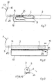
Ein Ausführungsbeispiel der Erfindung wird im folgenden anhand der Zeichnungen näher erläutert, und es zeigen:
- Fig. 1
- eine Gesamtansicht der Sonnenblende,
- Fig. 2
- eine aufgeklappte Draufsicht des aus zwei Schalen gebildeten Sonnenblendenkörpers der Sonnenblende nach Fig. 1 und
- Fig. 3 - 9
- Einzelheiten der Sonnenblende und eine Montagefolge.
- Fig. 1
- a general view of the sun visor,
- Fig. 2
- an unfolded top view of the sun visor body formed from two shells of the sun visor according to FIGS. 1 and
- 3 - 9
- Details of the sun visor and an assembly sequence.
Die Sonnenblende nach Fig. 1 besteht aus einem Sonnenblendenkörper 1, der
im Bereich seiner oberen Längskante 2 einen darin eingelagerten rohrförmigen
Hohlkörper 3 trägt, in dem ein Gleitkörper 4 axial verschiebbar aufgenommen ist,
welcher eine Achse 5 lagert. Die Sonnenblende weist weiterhin einen Lagerstift 6
zum Einrasten in ein nicht dargestelltes Gegenlager auf. Die Achse 5 besitzt eine
etwa L-förmige Ausbildung, deren langer Schenkel von dem Gleitkörper 4 und
deren kurzer Schenkel von einem Schwenklagerböckchen 7 aufgenommen ist.
Der Sonnenblendenkörper 1 ist üblicherweise auf dem langen Schenkel der
Achse 5 in der aus Fig. 1 ersichtlichen Lage angeordnet. Damit sich Fahrer und
Beifahrer eines Fahrzeugs vor einfallenden Sonnenstrahlen oder anderen Lichtquellen
schützen können, ist der Sonnenblendenkörper 1 oberhalb der Windschutzscheibe
an der Fahrzeugkarosserie befestigt und er kann vor die Windschutzscheibe
geklappt oder zu einer Seitenscheibe geschwenkt werden.
Darüber hinaus ist eine, durch den Doppelpfeil angedeutete verschiebbare
Anordnung des Sonnenblendenkörpers 1 auf dem langen Schenkel der Achse 5
vorgesehen. Insoweit entspricht die neue Sonnenblende im wesentlichen dem
Aufbau der Sonnenblende nach der EP 0 499 020 B1, so daß Einzelheiten des
Gleitkörpers 4 mit Andruckelement 8 und des Rast- und Verschiebemechanismusses
nicht näher zu erläutern sind.1 consists of a
Die neue Sonnenblende weist darüber hinaus eine im Sonnenblendenkörper 1
angeordnete Schalteinrichtung mit Schalter 9, eine Fernsteuerungseinheit 10 und
eine mehrere Leiterdrähte umfassende Leitung 11 auf.The new sun visor also has one in the
Wie aus Fig. 2 ersichtlich, weist der Sonnenblendenkörper 1 eine zweischalige
Bauart auf. Die Schalenhälften 12, 13 können z.B. aus geschäumten oder gespritzten
Schaumstoff bestehen. Nach dem Zusammenfügen der Schalenhälften
12, 13 erhält der Sonnenblendenkörper 1 in der Regel noch eine Umhüllung aus
z.B. textilen Dekormaterial. Zwischen den Schalenhälften 12, 13 befinden sich
die Funktionselemente der Sonnenblende, die zumeist weiter oben schon erwähnt
worden sind. Aus Fig. 2 ist ersichtlich, daß sich an den Hohlkörper 3 Endstopfen
14, 15 anschließen, die Teil einer zur Aussteifung des Sonnenblendenkörpers
dienenden Rahmenstruktur 16 sind, die aus Kunststoff-Spritzgußteilen
und damit verbundenen Drahtabschnitten bestehen kann. In den Endstopfen 14,
15 befinden sich nicht näher dargestellte Durchgangsöffnungen für die Leitung
11 sowie im Endstopfen 14 auch eine Durchgangsöffnung für die Achse 5.As can be seen from Fig. 2, the
Die für die Stromversorgung der Beleuchtungseinrichtung (nicht gezeigt) und der
Fernsteuerungseinheit 10 benötigte Leitung 11 umfaßt mehrere, z.B. wie dargestellt
drei Leiterdrähte 17, 18, 19. Bei der Montage wird die Leitung 11 zunächst
durch die hohle Achse 5 geführt (Fig. 3), wonach an das aus dem kurzen Achsschenkel
heraustretende Ende ein Steckerelement (nicht gezeigt) zum Anschluß
an die allgemeine Fahrzeugelektrik angeklemmt wird. Auf den langen Achsschenkel
ist zuvor ein Abschlußring 20 und ein Stopfen 14 der Rahmenstruktur
16 aufgeschoben worden. Die Leitung wird sodann durch den Gleitkörper 4
geführt, der auf dem Endbereich des langen Achsschenkels der Achse 5 verrastet
wird. Am Gleitkörper 4 ist ein Schalter 9 angeordnet, dessen Schaltglied 22
an der Achse 5 angreift und den Stromkreis für die nichtgezeigte Beleuchtungseinrichtung
unterbricht, sobald es im Bereich einer Achsenabflachung 23 zur
Anlage gelangt. Diese Anlage ist in der Regel dann gegeben, wenn der Sonnenblendenkörper
1 sich in seiner am Dachhimmel anliegenden Ruhelage befindet.
Einer der Leiterdrähte 17 - 19, z.B. der Leiterdraht 19 wird an den Schalter 9
angeschlossen und weitergeführt (Fig. 4). Die Leitung 11 mit den Leiterdrähten
17 - 19 wird dann zurückgeführt (Fig. 5), durchläuft einen Kabelkanal 24 im
Gleitkörper 4 und verläuft sodann mit losen Windungen 25 um die Achse 5 herum
(Fig. 7), um dann aus dem Hohlkörper 3 und dem Endstopfen 14 wieder herauszutreten,
um wiederum zurückgeführt zu werden mit einem parallelen Verlauf
zum Hohlkörper 3. Die freien Enden der Leiterdrähte 17 - 19 werden ggf. an
einen Mikroschalter 26 und über diesen wie auch direkt an ein an der Rahmenstruktur
16 festgelegtes Kuppelelement 30 für die Fernsteuerungseinheit 10
angeschlossen (Fig. 8). Der Mikroschalter wird vorgesehen, wenn der Sonnenblendenkörper
mit einem Spiegel 27 und einem Spiegelabdeckschieber 28, der
mit dem Mikroschalter 26 zusammenwirkt, ausgestattet wird.The for the power supply of the lighting device (not shown) and the
Die Baueinheit gemäß Fig. 8 wird in eine Sonnenblendenkörperhäfte 12, wie in
Fig. 2 gezeigt, eingelegt und durch die zweite Sonnenblendenkörperhälfte 13, die
mit der ersten über ein Filmscharnier verbunden sein kann, abgedeckt. Ggf. sind
die Sonnenblendenkörperhälften 12, 13 miteinander zu verkleben oder anderweitig
aneinander festzulegen. Die Festlegung der Sonnenblendenkörperhälften
12, 13 kann auch durch ein Dekormaterial 29 erfolgen, mit dem ein Sonnenblendenkörperrohling
üblicherweise umhüllt ist. Nach dem Umhüllen erfolgt noch
ein Einklipsen des Abschlußrings 20 in den Endstopfen 14 unter Gewährleistung
eines sauberen Abschlusses.8 is in a sun
Beim Verschieben des Sonnenblendenkörpers 1 längs des langen Schenkels der
Achse 5 bleibt die Stromzuführung für die Fernsteuerungseinheit 10 stets aufrechterhalten,
weil für die Leitung 11 dank der losen Windungen 25 genügend
Reservematerial zur Verfügung steht. Die neue Sonnenblende ist also klappbar,
verschwenkbar und verschiebbar und zudem mit einer Stromzuführung ausgerüstet,
die in jeder Position des Sonnenblendenkörpers 1 eine Stromzufuhr zur
Fernsteuerungseinheit gewährleistet. Auch ist eine Zwangsausschaltung einer
Beleuchtungseinrichtung gegeben, die auch bei einer offenen Schiebedeckelposition
wirksam ist.When moving the
Claims (7)
Applications Claiming Priority (2)
| Application Number | Priority Date | Filing Date | Title |
|---|---|---|---|
| DE10017046 | 2000-04-05 | ||
| DE10017046A DE10017046C1 (en) | 2000-04-05 | 2000-04-05 | Automobile sun visor has incorporated switch and garage door remote control device supplied via current lead fed through hollow pivot axis for sun visor body |
Publications (2)
| Publication Number | Publication Date |
|---|---|
| EP1142736A1 true EP1142736A1 (en) | 2001-10-10 |
| EP1142736B1 EP1142736B1 (en) | 2007-09-26 |
Family
ID=7637751
Family Applications (1)
| Application Number | Title | Priority Date | Filing Date |
|---|---|---|---|
| EP01105537A Expired - Lifetime EP1142736B1 (en) | 2000-04-05 | 2001-03-06 | Sunvisor for vehicles |
Country Status (6)
| Country | Link |
|---|---|
| US (1) | US6435593B2 (en) |
| EP (1) | EP1142736B1 (en) |
| JP (1) | JP2001310628A (en) |
| AT (1) | ATE374126T1 (en) |
| DE (2) | DE10017046C1 (en) |
| ES (1) | ES2292503T3 (en) |
Cited By (1)
| Publication number | Priority date | Publication date | Assignee | Title |
|---|---|---|---|---|
| EP1661744A1 (en) * | 2004-11-30 | 2006-05-31 | Grupo Antolin Ingenieria, S.A. | Sliding sun visor |
Families Citing this family (28)
| Publication number | Priority date | Publication date | Assignee | Title |
|---|---|---|---|---|
| US6698814B1 (en) | 2002-10-02 | 2004-03-02 | Grupo Antolin Ingenieria, S.A. | Slidable sun visor |
| US7311427B2 (en) * | 2002-11-20 | 2007-12-25 | Johnson Controls Technology Company | Covered illuminated vanity mirror assembly |
| CA2472829C (en) * | 2003-07-08 | 2012-04-24 | Cooper Technologies Company | Fuse with metallic state indicator |
| US7217017B2 (en) * | 2003-08-25 | 2007-05-15 | Johnson Controls Technology Company | Vanity for a vehicle |
| US6962385B2 (en) * | 2003-10-15 | 2005-11-08 | Irvin Automotive Products, Inc. | Sliding visor |
| ES2265215B1 (en) * | 2004-03-10 | 2007-11-01 | Intier Automotive Interiors Zippex, S.A.U. | EXTENSIBLE PARASOL PERFECTED FOR VEHICLES. |
| US7128451B2 (en) * | 2004-06-22 | 2006-10-31 | General Motors Corporation | Ingress and egress lighting integrated to sun visor systems |
| US7055884B2 (en) * | 2004-10-25 | 2006-06-06 | Lear Corporation | Low-friction sleeve insert for a visor bearing |
| DE102004060758B4 (en) * | 2004-12-15 | 2013-08-01 | Johnson Controls Interiors Gmbh & Co. Kg | Mirror module for a sun visor for a vehicle, sun visor for a motor vehicle |
| US20080007020A1 (en) * | 2006-07-06 | 2008-01-10 | Holman David L | Tray for use on a walker |
| US7461886B1 (en) | 2006-10-04 | 2008-12-09 | Jianhua Wang | Visor capable of illumination when sliding |
| DE102007006357A1 (en) * | 2007-02-08 | 2008-08-21 | Dura Automotive Body & Glass Systems Gmbh | Sliding door for a motor vehicle |
| US7534018B2 (en) * | 2007-03-16 | 2009-05-19 | International Automotive Components North America, Inc. | Illuminated visor vanity |
| KR101595715B1 (en) * | 2008-10-15 | 2016-02-26 | 존슨 컨트롤스 테크놀러지 컴퍼니 | Channel for slide-on-rod visors |
| US7963582B2 (en) * | 2008-10-18 | 2011-06-21 | Irvin Automotive Products, Inc. | Sliding visor |
| RU2511847C2 (en) | 2008-12-30 | 2014-04-10 | ЭлДжи ЭЛЕКТРОНИКС ИНК. | Laundry machine |
| US8627510B2 (en) * | 2009-08-03 | 2014-01-07 | Lexmark International, Inc. | Electronic device and method for operating the electronic device |
| US8425094B2 (en) | 2010-06-09 | 2013-04-23 | Ford Global Technologies, Llc | Vehicle vanity and light assembly and visor having vanity and dome lighting |
| US8382189B2 (en) * | 2010-10-05 | 2013-02-26 | Ford Global Technologies, Llc | Molded vanity assembly and method |
| US8556325B2 (en) | 2011-09-20 | 2013-10-15 | Irvin Automotive Products, Inc. | Sliding visor |
| US9834068B2 (en) * | 2013-12-18 | 2017-12-05 | Hyundai Motor Company | Sun visor for vehicle |
| US10737559B2 (en) | 2014-12-16 | 2020-08-11 | Irvin Automotive Products, LLC | Visor |
| US20170240103A1 (en) | 2016-02-23 | 2017-08-24 | Motus Integrated Technologies | Vehicle sun visor assembly having an electrical system |
| US10688850B2 (en) | 2018-03-13 | 2020-06-23 | Irvin Automotive Products, LLC | Sliding visor |
| US10864804B2 (en) | 2019-02-28 | 2020-12-15 | Irvin Automotive Products, LLC | Sliding thin visor |
| US10870337B2 (en) | 2019-02-28 | 2020-12-22 | Irvin Automotive Products, LLC | Thin visor |
| JP7313988B2 (en) * | 2019-09-06 | 2023-07-25 | 共和産業株式会社 | vehicle sun visor |
| CN114572084A (en) * | 2020-11-30 | 2022-06-03 | 上海汽车集团股份有限公司 | Carrying platform for vehicle configuration and configuration module |
Citations (5)
| Publication number | Priority date | Publication date | Assignee | Title |
|---|---|---|---|---|
| EP0374582A2 (en) * | 1988-12-19 | 1990-06-27 | Gebr. Happich GmbH | Sun visor for vehicles |
| DE29709454U1 (en) * | 1997-05-30 | 1997-07-31 | Magna Zippex Autotechnik Gmbh | Sun visors for vehicles |
| US5720509A (en) * | 1995-07-12 | 1998-02-24 | Prince Corp | Integral molded visor and vehicle accessory |
| US5810420A (en) * | 1995-06-06 | 1998-09-22 | Prince Corporation | Memo visor |
| WO1998057216A2 (en) * | 1997-06-12 | 1998-12-17 | Lci Computer Group, N.V. | Liquid crystal display in a sun visor |
Family Cites Families (4)
| Publication number | Priority date | Publication date | Assignee | Title |
|---|---|---|---|---|
| DE3603852A1 (en) * | 1986-02-07 | 1987-08-13 | Happich Gmbh Gebr | SUN VISOR FOR VEHICLES |
| DE4104032C1 (en) * | 1991-02-09 | 1992-04-16 | Gebr. Happich Gmbh, 5600 Wuppertal, De | |
| DE4328890C1 (en) * | 1993-08-27 | 1994-12-22 | Happich Gmbh Gebr | Sun visor for vehicles |
| US6174019B1 (en) * | 1998-02-26 | 2001-01-16 | Prince Corporation | Extruded visor control |
-
2000
- 2000-04-05 DE DE10017046A patent/DE10017046C1/en not_active Expired - Fee Related
-
2001
- 2001-03-06 DE DE50113047T patent/DE50113047D1/en not_active Expired - Lifetime
- 2001-03-06 ES ES01105537T patent/ES2292503T3/en not_active Expired - Lifetime
- 2001-03-06 AT AT01105537T patent/ATE374126T1/en not_active IP Right Cessation
- 2001-03-06 EP EP01105537A patent/EP1142736B1/en not_active Expired - Lifetime
- 2001-04-02 JP JP2001103975A patent/JP2001310628A/en not_active Withdrawn
- 2001-04-05 US US09/827,261 patent/US6435593B2/en not_active Expired - Lifetime
Patent Citations (5)
| Publication number | Priority date | Publication date | Assignee | Title |
|---|---|---|---|---|
| EP0374582A2 (en) * | 1988-12-19 | 1990-06-27 | Gebr. Happich GmbH | Sun visor for vehicles |
| US5810420A (en) * | 1995-06-06 | 1998-09-22 | Prince Corporation | Memo visor |
| US5720509A (en) * | 1995-07-12 | 1998-02-24 | Prince Corp | Integral molded visor and vehicle accessory |
| DE29709454U1 (en) * | 1997-05-30 | 1997-07-31 | Magna Zippex Autotechnik Gmbh | Sun visors for vehicles |
| WO1998057216A2 (en) * | 1997-06-12 | 1998-12-17 | Lci Computer Group, N.V. | Liquid crystal display in a sun visor |
Cited By (1)
| Publication number | Priority date | Publication date | Assignee | Title |
|---|---|---|---|---|
| EP1661744A1 (en) * | 2004-11-30 | 2006-05-31 | Grupo Antolin Ingenieria, S.A. | Sliding sun visor |
Also Published As
| Publication number | Publication date |
|---|---|
| US6435593B2 (en) | 2002-08-20 |
| US20010050493A1 (en) | 2001-12-13 |
| EP1142736B1 (en) | 2007-09-26 |
| DE50113047D1 (en) | 2007-11-08 |
| JP2001310628A (en) | 2001-11-06 |
| DE10017046C1 (en) | 2001-06-13 |
| ATE374126T1 (en) | 2007-10-15 |
| ES2292503T3 (en) | 2008-03-16 |
Similar Documents
| Publication | Publication Date | Title |
|---|---|---|
| EP1142736B1 (en) | Sunvisor for vehicles | |
| DE2703447C3 (en) | Sun visors for vehicles | |
| EP0242681B1 (en) | Stream-lining device for a vehicle | |
| EP1666291B1 (en) | Window roller blind with simplified assembly | |
| EP0170167B1 (en) | Sun visor for vehicles | |
| EP0371300B1 (en) | Sun visor for vehicles | |
| DE4328890C1 (en) | Sun visor for vehicles | |
| DE10316592A1 (en) | Retractable protective awning and motor vehicle with protective awning | |
| DE60224227T2 (en) | SUNSHADE WITH LIGHTING FOR VEHICLES | |
| DE10020106C1 (en) | Vehicle sun visor is a rectangular body which can swing around a short vertical axis and a long longitudinal axis for positioning whether at a windscreen or a side window | |
| EP0653322A1 (en) | Pivot shaft for a vehicle sunvisor | |
| EP0368132A2 (en) | Sun visor for vehicles | |
| EP0406519B1 (en) | Vanity mirror or the like for vehicles | |
| EP0652125B1 (en) | Sun visor for vehicles | |
| EP0374582B1 (en) | Sun visor for vehicles | |
| DE10017047A1 (en) | Sunshade for vehicle has electrical lighting device switch, remote control unit for automatic garage door opener, cable containing conducting wire(s) with excess for sunshade movement | |
| DE2807982C2 (en) | Sun visors for vehicles | |
| EP1052125A2 (en) | Glare protection device for vehicles | |
| DE3525149C1 (en) | Sun visors for a motor vehicle, which are arranged in the transition regions between the roof and the side walls | |
| DE3923922A1 (en) | Vehicular exterior mirror adjustable by motor and gearing - has resiliently-mounted motor in fixed portion of housing for retraction of normally deployed pivotable portion | |
| DE10144858C1 (en) | Sun shade for motor vehicle has stabilizing frame made of injection moulded plastics with integral light switch | |
| EP0834968B1 (en) | Device for transferring current between two terminals moving relatively to one another | |
| DE7702394U1 (en) | SUN VISOR FOR VEHICLES | |
| DE102004046784B4 (en) | Retractable sun visor for vehicles | |
| DE7721482U1 (en) | SUN VISOR FOR VEHICLES |
Legal Events
| Date | Code | Title | Description |
|---|---|---|---|
| PUAI | Public reference made under article 153(3) epc to a published international application that has entered the european phase |
Free format text: ORIGINAL CODE: 0009012 |
|
| AK | Designated contracting states |
Kind code of ref document: A1 Designated state(s): AT BE CH CY DE DK ES FI FR GB GR IE IT LI LU MC NL PT SE TR |
|
| AX | Request for extension of the european patent |
Free format text: AL;LT;LV;MK;RO;SI |
|
| 17P | Request for examination filed |
Effective date: 20011210 |
|
| AKX | Designation fees paid |
Free format text: AT BE CH CY DE DK ES FI FR GB GR IE IT LI LU MC NL PT SE TR |
|
| GRAP | Despatch of communication of intention to grant a patent |
Free format text: ORIGINAL CODE: EPIDOSNIGR1 |
|
| GRAS | Grant fee paid |
Free format text: ORIGINAL CODE: EPIDOSNIGR3 |
|
| GRAA | (expected) grant |
Free format text: ORIGINAL CODE: 0009210 |
|
| AK | Designated contracting states |
Kind code of ref document: B1 Designated state(s): AT BE CH CY DE DK ES FI FR GB GR IE IT LI LU MC NL PT SE TR |
|
| REG | Reference to a national code |
Ref country code: GB Ref legal event code: FG4D Free format text: NOT ENGLISH |
|
| REG | Reference to a national code |
Ref country code: CH Ref legal event code: EP |
|
| REF | Corresponds to: |
Ref document number: 50113047 Country of ref document: DE Date of ref document: 20071108 Kind code of ref document: P |
|
| REG | Reference to a national code |
Ref country code: IE Ref legal event code: FG4D Free format text: LANGUAGE OF EP DOCUMENT: GERMAN |
|
| GBT | Gb: translation of ep patent filed (gb section 77(6)(a)/1977) |
Effective date: 20071205 |
|
| PG25 | Lapsed in a contracting state [announced via postgrant information from national office to epo] |
Ref country code: FI Free format text: LAPSE BECAUSE OF FAILURE TO SUBMIT A TRANSLATION OF THE DESCRIPTION OR TO PAY THE FEE WITHIN THE PRESCRIBED TIME-LIMIT Effective date: 20070926 |
|
| NLV1 | Nl: lapsed or annulled due to failure to fulfill the requirements of art. 29p and 29m of the patents act | ||
| REG | Reference to a national code |
Ref country code: ES Ref legal event code: FG2A Ref document number: 2292503 Country of ref document: ES Kind code of ref document: T3 |
|
| ET | Fr: translation filed | ||
| PG25 | Lapsed in a contracting state [announced via postgrant information from national office to epo] |
Ref country code: GR Free format text: LAPSE BECAUSE OF FAILURE TO SUBMIT A TRANSLATION OF THE DESCRIPTION OR TO PAY THE FEE WITHIN THE PRESCRIBED TIME-LIMIT Effective date: 20071227 Ref country code: NL Free format text: LAPSE BECAUSE OF FAILURE TO SUBMIT A TRANSLATION OF THE DESCRIPTION OR TO PAY THE FEE WITHIN THE PRESCRIBED TIME-LIMIT Effective date: 20070926 |
|
| REG | Reference to a national code |
Ref country code: IE Ref legal event code: FD4D |
|
| PG25 | Lapsed in a contracting state [announced via postgrant information from national office to epo] |
Ref country code: PT Free format text: LAPSE BECAUSE OF FAILURE TO SUBMIT A TRANSLATION OF THE DESCRIPTION OR TO PAY THE FEE WITHIN THE PRESCRIBED TIME-LIMIT Effective date: 20080226 |
|
| PG25 | Lapsed in a contracting state [announced via postgrant information from national office to epo] |
Ref country code: SE Free format text: LAPSE BECAUSE OF FAILURE TO SUBMIT A TRANSLATION OF THE DESCRIPTION OR TO PAY THE FEE WITHIN THE PRESCRIBED TIME-LIMIT Effective date: 20071226 |
|
| PG25 | Lapsed in a contracting state [announced via postgrant information from national office to epo] |
Ref country code: DK Free format text: LAPSE BECAUSE OF FAILURE TO SUBMIT A TRANSLATION OF THE DESCRIPTION OR TO PAY THE FEE WITHIN THE PRESCRIBED TIME-LIMIT Effective date: 20070926 |
|
| PLBE | No opposition filed within time limit |
Free format text: ORIGINAL CODE: 0009261 |
|
| STAA | Information on the status of an ep patent application or granted ep patent |
Free format text: STATUS: NO OPPOSITION FILED WITHIN TIME LIMIT |
|
| 26N | No opposition filed |
Effective date: 20080627 |
|
| BERE | Be: lapsed |
Owner name: JOHNSON CONTROLS INTERIORS G.M.B.H. & CO. KG Effective date: 20080331 |
|
| PG25 | Lapsed in a contracting state [announced via postgrant information from national office to epo] |
Ref country code: IE Free format text: LAPSE BECAUSE OF FAILURE TO SUBMIT A TRANSLATION OF THE DESCRIPTION OR TO PAY THE FEE WITHIN THE PRESCRIBED TIME-LIMIT Effective date: 20070926 Ref country code: MC Free format text: LAPSE BECAUSE OF NON-PAYMENT OF DUE FEES Effective date: 20080331 |
|
| REG | Reference to a national code |
Ref country code: CH Ref legal event code: PL |
|
| PG25 | Lapsed in a contracting state [announced via postgrant information from national office to epo] |
Ref country code: LI Free format text: LAPSE BECAUSE OF NON-PAYMENT OF DUE FEES Effective date: 20080331 Ref country code: CH Free format text: LAPSE BECAUSE OF NON-PAYMENT OF DUE FEES Effective date: 20080331 |
|
| PG25 | Lapsed in a contracting state [announced via postgrant information from national office to epo] |
Ref country code: BE Free format text: LAPSE BECAUSE OF NON-PAYMENT OF DUE FEES Effective date: 20080331 |
|
| PG25 | Lapsed in a contracting state [announced via postgrant information from national office to epo] |
Ref country code: CY Free format text: LAPSE BECAUSE OF FAILURE TO SUBMIT A TRANSLATION OF THE DESCRIPTION OR TO PAY THE FEE WITHIN THE PRESCRIBED TIME-LIMIT Effective date: 20070926 |
|
| PG25 | Lapsed in a contracting state [announced via postgrant information from national office to epo] |
Ref country code: AT Free format text: LAPSE BECAUSE OF NON-PAYMENT OF DUE FEES Effective date: 20080306 |
|
| PG25 | Lapsed in a contracting state [announced via postgrant information from national office to epo] |
Ref country code: LU Free format text: LAPSE BECAUSE OF NON-PAYMENT OF DUE FEES Effective date: 20080306 |
|
| PG25 | Lapsed in a contracting state [announced via postgrant information from national office to epo] |
Ref country code: TR Free format text: LAPSE BECAUSE OF FAILURE TO SUBMIT A TRANSLATION OF THE DESCRIPTION OR TO PAY THE FEE WITHIN THE PRESCRIBED TIME-LIMIT Effective date: 20070926 |
|
| PGFP | Annual fee paid to national office [announced via postgrant information from national office to epo] |
Ref country code: DE Payment date: 20140331 Year of fee payment: 14 |
|
| PGFP | Annual fee paid to national office [announced via postgrant information from national office to epo] |
Ref country code: ES Payment date: 20140320 Year of fee payment: 14 Ref country code: IT Payment date: 20140326 Year of fee payment: 14 Ref country code: FR Payment date: 20140319 Year of fee payment: 14 |
|
| PGFP | Annual fee paid to national office [announced via postgrant information from national office to epo] |
Ref country code: GB Payment date: 20140319 Year of fee payment: 14 |
|
| REG | Reference to a national code |
Ref country code: DE Ref legal event code: R119 Ref document number: 50113047 Country of ref document: DE |
|
| GBPC | Gb: european patent ceased through non-payment of renewal fee |
Effective date: 20150306 |
|
| PG25 | Lapsed in a contracting state [announced via postgrant information from national office to epo] |
Ref country code: IT Free format text: LAPSE BECAUSE OF NON-PAYMENT OF DUE FEES Effective date: 20150306 |
|
| REG | Reference to a national code |
Ref country code: FR Ref legal event code: ST Effective date: 20151130 |
|
| PG25 | Lapsed in a contracting state [announced via postgrant information from national office to epo] |
Ref country code: GB Free format text: LAPSE BECAUSE OF NON-PAYMENT OF DUE FEES Effective date: 20150306 Ref country code: DE Free format text: LAPSE BECAUSE OF NON-PAYMENT OF DUE FEES Effective date: 20151001 |
|
| PG25 | Lapsed in a contracting state [announced via postgrant information from national office to epo] |
Ref country code: FR Free format text: LAPSE BECAUSE OF NON-PAYMENT OF DUE FEES Effective date: 20150331 |
|
| REG | Reference to a national code |
Ref country code: ES Ref legal event code: FD2A Effective date: 20160429 |
|
| PG25 | Lapsed in a contracting state [announced via postgrant information from national office to epo] |
Ref country code: ES Free format text: LAPSE BECAUSE OF NON-PAYMENT OF DUE FEES Effective date: 20150307 |