EP1143466A1 - Lockable microelectromechanical actuators using thermoplastic materials, and methods of operating same - Google Patents
Lockable microelectromechanical actuators using thermoplastic materials, and methods of operating same Download PDFInfo
- Publication number
- EP1143466A1 EP1143466A1 EP01302513A EP01302513A EP1143466A1 EP 1143466 A1 EP1143466 A1 EP 1143466A1 EP 01302513 A EP01302513 A EP 01302513A EP 01302513 A EP01302513 A EP 01302513A EP 1143466 A1 EP1143466 A1 EP 1143466A1
- Authority
- EP
- European Patent Office
- Prior art keywords
- heater
- thermoplastic material
- actuator
- microelectromechanical
- microelectromechanical actuator
- Prior art date
- Legal status (The legal status is an assumption and is not a legal conclusion. Google has not performed a legal analysis and makes no representation as to the accuracy of the status listed.)
- Granted
Links
Images


Classifications
-
- B—PERFORMING OPERATIONS; TRANSPORTING
- B81—MICROSTRUCTURAL TECHNOLOGY
- B81B—MICROSTRUCTURAL DEVICES OR SYSTEMS, e.g. MICROMECHANICAL DEVICES
- B81B7/00—Microstructural systems; Auxiliary parts of microstructural devices or systems
- B81B7/02—Microstructural systems; Auxiliary parts of microstructural devices or systems containing distinct electrical or optical devices of particular relevance for their function, e.g. microelectro-mechanical systems [MEMS]
-
- H—ELECTRICITY
- H01—ELECTRIC ELEMENTS
- H01H—ELECTRIC SWITCHES; RELAYS; SELECTORS; EMERGENCY PROTECTIVE DEVICES
- H01H61/00—Electrothermal relays
- H01H61/02—Electrothermal relays wherein the thermally-sensitive member is heated indirectly, e.g. resistively, inductively
-
- H—ELECTRICITY
- H01—ELECTRIC ELEMENTS
- H01H—ELECTRIC SWITCHES; RELAYS; SELECTORS; EMERGENCY PROTECTIVE DEVICES
- H01H1/00—Contacts
- H01H1/0036—Switches making use of microelectromechanical systems [MEMS]
-
- H—ELECTRICITY
- H01—ELECTRIC ELEMENTS
- H01H—ELECTRIC SWITCHES; RELAYS; SELECTORS; EMERGENCY PROTECTIVE DEVICES
- H01H1/00—Contacts
- H01H1/0036—Switches making use of microelectromechanical systems [MEMS]
- H01H2001/0042—Bistable switches, i.e. having two stable positions requiring only actuating energy for switching between them, e.g. with snap membrane or by permanent magnet
-
- H—ELECTRICITY
- H01—ELECTRIC ELEMENTS
- H01H—ELECTRIC SWITCHES; RELAYS; SELECTORS; EMERGENCY PROTECTIVE DEVICES
- H01H61/00—Electrothermal relays
- H01H2061/006—Micromechanical thermal relay
Definitions
- This invention relates to electromechanical systems, and more particularly to microelectromechanical systems and operating methods therefor.
- MEMS Microelectromechanical systems
- electromechanical devices such as relays, actuators, valves and sensors.
- MEMS devices are potentially low-cost devices, due to the use of microelectronic fabrication techniques.
- New functionality also may be provided, because MEMS devices can be much smaller than conventional electromechanical devices.
- MEMS actuators may use one or more beams that are fixed at one or both ends. These actuators may be actuated electrostatically, magnetically, thermally and/or using other forms of energy.
- Means are provided for applying heat to the arched beam to cause further arching of the beam as a result of thermal expansion thereof, to thereby cause displacement of the arched beam.
- a coupler can be used to mechanically couple multiple arched beams.
- At least one compensating arched beam also can be included which is arched in a second direction opposite to the multiple arched beams and also is mechanically coupled to the coupler.
- the compensating arched beams can compensate for ambient temperature or other effects to allow for self-compensating actuators and sensors.
- Thermal arched beams can be used to provide actuators, relays, sensors, microvalves and other MEMS devices. Thermal arched beam microelectromechanical devices and associated fabrication methods also are described in U.S. Patent 5,955,817 to Dhuler et al.
- conventional MEMS actuators may require continuous application of an electrostatic potential, a magnetic field, electric current and/or other energy to the MEMS actuator in order to maintain the actuator in a set or actuated position. This may consume excessive power. Moreover, an interruption of power may cause the actuator to reset.
- Lockable microelectromechanical actuators include a microelectromechanical actuator, a thermoplastic material that is coupled to the microelectromechanical actuator to lock the microelectromechanical actuator, and a heater that melts the thermoplastic material to allow movement of the microelectromechanical actuator.
- the thermoplastic material solidifies, movement of the microelectromechanical actuator can be locked, without the need to maintain power, in the form of electric, magnetic and/or electrostatic energy, to the microelectromechanical actuator, and without the need to rely on mechanical friction to hold the microelectromechanical actuator in place.
- the thermoplastic material can act as a glue to hold structures in a particular position without the need for continuous power application.
- the thermoplastic material can solidify rapidly enough to lock the microelectromechanical actuator at or near its most recent position.
- Embodiments of the present invention preferably are formed on a substrate, wherein the heater is on the substrate and wherein a portion of the microelectromechanical actuator is adjacent and spaced apart from the heater, and wherein the thermoplastic material is between the heater and the portion of the microelectromechanical actuator.
- the microelectromechanical actuators may move along the substrate to provide embodiments of "in-plane” microelectromechanical actuators.
- the actuators may move out of the plane of the substrate, for example, orthogonal to the substrate, to provide embodiments of "out-of-plane" microelectromechanical actuators.
- Embodiments of the present invention may be used with actuators that are actuated using electrostatic, magnetic, thermal and/or other forms of actuation.
- the heater that melts the thermoplastic material also may be used to actuate the thermally actuated microelectromechanical actuator.
- the heater that melts the thermoplastic material is a first heater and the lockable microelectromechanical actuator also includes a second heater that is thermally coupled to the microelectromechanical actuator, such that the microelectromechanical actuator moves in response to actuation of the second heater.
- Embodiments of lockable microelectromechanical actuators that employ first and second heaters also may include a thermal isolator that is configured to isolate the second heater from the thermoplastic material.
- the heater may be configured to melt the thermoplastic material and actuate the thermal actuator upon application of a first amount of power thereto.
- the heater also may be configured to melt the thermoplastic material without actuating the thermal actuator upon application of second amount of power thereto that is less than the first amount of power.
- the actuator can be restored to its starting or unactuated position by applying sufficient power to the heater to melt the thermoplastic material, but not enough power to actuate the actuator. With the thermoplastic material melted, viscous flow can occur and permit the actuator to relax back to its neutral position.
- a reversible system may be provided, that can allow continuous variability and simple control setup.
- Thermoplastic materials according to the present invention may include thermoplastic polymers, thermoplastic monomers, solders and/or any other material that changes from a solid to a liquid material over a temperature range that is compatible with the ambient temperature in which the lockable microelectromechanical actuator will be used.
- Embodiments of lockable microelectromechanical actuators according to the invention may be combined with a relay contact, an optical attenuator, an optical switch, a variable circuit element such as a variable resistor, a valve, a circuit breaker and/or other elements to provide a microelectromechanical device.
- Embodiments of thermal arched beam microelectromechanical actuators include a substrate, spaced apart supports on the substrate and an arched beam that extends between the spaced apart supports, and that further arches upon application of heat thereto for movement along the substrate.
- a thermoplastic material is coupled to the arched beam to lock the arched beam.
- a heater melts the thermoplastic material to allow movement of the arched beam.
- the heater is on the substrate, the arched beam is adjacent and spaced apart from the heater, and the thermoplastic material is between the heater and the arched beam.
- Embodiments of lockable thermal arched beam microelectromechanical actuators use the heater both to further arch the arched beam and to melt the thermoplastic material.
- Alternative embodiments use a first heater to melt the thermoplastic material and a second heater that is thermally coupled to the arched beam to further arch the arched beam.
- These alternative embodiments also may include a thermal isolator that is configured to thermally isolate the second heater from the thermoplastic material.
- the heater may be configured to melt the thermoplastic material and to further arch the arched beam upon application of a first amount of power thereto.
- the heater also may be configured to melt the thermoplastic material without further arching the arched beam upon application of a second amount of power thereto that is less than the first amount of power.
- Embodiments of lockable thermal arched beam microelectromechanical actuators can use the thermoplastic materials selected that were described above, and can be combined with other elements as was described above.
- lockable thermal arched beam microelectromechanical actuators use first and second parallel arched beams that further arch upon application of heat thereto.
- a coupler is attached to the first and second arched beams, such that the first and second arched beams move in tandem along the substrate upon application of heat thereto.
- the thermoplastic material may extend between the coupler and the heater.
- the coupler may include an aperture that extends therethrough from opposite the heater to adjacent the heater and that is configured to allow placement of the thermoplastic material between the coupler and the heater.
- Microelectromechanical actuators may be operated, according to embodiments of the present invention, by melting a thermoplastic material that is coupled to the microelectromechanical actuator to unlock the microelectromechanical actuator.
- the unlocked microelectromechanical actuator may be actuated.
- the melted thermoplastic material then may be allowed to solidify to lock the microelectromechanical actuator.
- the melting and actuating may be performed simultaneously.
- melting of the thermoplastic material is performed by applying power to a heater that is thermally coupled to the thermoplastic material. The melted material is solidified by removing the power from the heater.
- the microelectromechanical actuator is a thermally actuated microelectromechanical actuator wherein the heater also is thermally coupled to the thermally actuated microelectromechanical actuator. Power is applied to the heater to actuate the thermally actuated microelectromechanical actuator. Melting and actuating may be performed simultaneously by applying power to the heater.
- the microelectromechanical actuator includes a first heater that is thermally coupled to the thermoplastic material and includes a second heater that is thermally coupled to the thermally actuated microelectromechanical actuator
- melting may be performed by applying power to the first heater to melt the thermoplastic material.
- Actuating may be performed by applying power to the second heater, to actuate the thermally actuated microelectromechanical actuator. Power then may be removed from the heater, to allow the melted thermoplastic material to solidify.
- the step of allowing the melted thermoplastic material to solidify may be followed by again melting the thermoplastic material to again unlock the microelectromechanical actuator.
- the microelectromechanical actuator then can return to its neutral or retracted position.
- the microelectromechanical actuator can be unlocked and deactuated.
- the step of again melting the thermoplastic material may be performed by applying power to the heater that is sufficient to melt the thermoplastic material, but is insufficient to actuate the thermally actuated microelectromechanical actuator. The actuator thereby can deactuate or retract.
- the step of again melting the thermoplastic material may be embodied by applying power to the first heater to melt the thermoplastic material without applying power to the second heater.
- lockable microelectromechanical actuators including lockable thermal arched beam microelectromechanical actuators, may be provided. These actuators need not consume power to remain actuated and need not rely on mechanical friction to maintain actuation.
- Thermoplastic materials also may be used to produce lockable large scale actuators that are not microelectromechanical actuators.
- lockable thermal arched beam microelectromechanical actuators 10 include a substrate 12 , such as a silicon semiconductor substrate, spaced apart supports 14a and 14b on the substrate, and one or more arched beams 16 that extend between the spaced apart supports 14a and 14b and that further arch upon application of heat thereto in the direction shown by arrow 18 for movement along the substrate 12 . It will be understood that a single arched beam 16 may be used.
- a plurality of arched beams 16 such as four arched beams 16 in Figures 1A and 2A, may be used, that are coupled to common supports and/or individual supports.
- any reference to a beam also shall include multiple beams, and any reference to multiple beams also shall include a single beam.
- a coupler may be attached to the arched beams 16 , such that the arched beams 16 move in tandem along the substrate 12 upon application of heat thereto.
- heat may be applied to the arched beams 16 by passing current through the beams and/or by an external heater.
- the design and operation of thermal arched beams as described in this paragraph are well known to those having skill in the art and need not be described further herein.
- thermoplastic material 20 is coupled to the arched beam 16 to lock the arched beam.
- a heater 24 also is provided that melts the thermoplastic material, to allow movement of the arched beam.
- the heater 24 may be provided on the substrate 12 as illustrated. In other embodiments, the heater may be coupled to the arched beams 16 and/or the coupler 22 , to move with movement of these elements.
- the heater 24 is on the substrate 12 , and the arched beams 16 are adjacent and spaced apart from the heater.
- the thermoplastic material is between the heater and the arched beams 16 . More preferably, as shown in Figure 1A, the thermoplastic material is between the coupler 22 and the heater 24 .
- the thermoplastic material 20 may be formed between the coupler 22 and the heater 24 by forming the thermoplastic material 20 on the heater prior to forming the coupler 22 thereon.
- a solid thermoplastic material may be placed adjacent the gap (such as a 1 ⁇ m gap) between the heater 24 and the coupler 22 after fabrication of the coupler 22 .
- the heater 24 then may be activated to melt the thermoplastic material 20 , and allow it to creep between the heater 24 and coupler 22 by capillary action.
- thermoplastic material becomes soft (liquid) when heated and hard (solid) when cooled.
- Thermoplastic materials also may be referred to herein as Phase-Change Materials (PCM).
- PCM Phase-Change Materials
- Many thermoplastic materials are known to those having skill in the art and may be used in embodiments of the present invention.
- a thermoplastic polymer may be used.
- An example of a thermoplastic polymer that may be used is CrystalbondTM 509, marketed by Aremco Products, Inc., Valley Cottage, NY. As described in the Aremco Products web site, www.aremco.com, CrystalbondTM 509 is a washaway adhesive that may be used to temporarily mount products that require dicing, polishing and/or other machining processes.
- CrystalbondTM 509 has a flow point of 250°F (121°C) and a viscosity of 6000 cps.
- a thermoplastic polymer that may be used is polyethylene glycol, which is widely available in various molecular weights. As is known to those having skill in the art, the melting temperature of polyethylene glycol can be a function of the molecular weight, so that a variety of melting points may be selected for various applications. Thermoplastic monomers also may be used.
- the thermoplastic material preferably should be selected so that it remains in solid form in the range of ambient temperatures over which the microelectromechanical actuator may be used, yet can be melted at a temperature range that is slightly higher than the highest ambient temperature in which the microelectromechanical actuator may be used.
- the thermoplastic material preferably should melt over a narrow temperature range.
- the thermoplastic material also preferably should wet to the thermal arched beam 16 and/or the coupler 22 to which it is coupled. Thus, when the thermal arched beams and/or coupler are nickel, the thermoplastic material preferably should wet to nickel.
- the thermoplastic material also preferably should not wet to the heater 24 so that it can move with the thermal arched beam and/or coupler upon actuation thereof. Thus, when the heater 24 comprises polysilicon, the thermoplastic material preferably should not wet to polysilicon.
- solder may be used as a thermoplastic material 20.
- conventional lead-tin eutectic solder may have a melting point of about 240°C.
- Other thermoplastic materials may be used, depending upon the ambient temperature, the materials associated with the microelectromechanical actuator, and/or other factors.
- thermoplastic material 20 preferably is maintained in solid form by not applying heat thereto from heater 24. Thus, chatter or other movement of the actuator 10 may be prevented.
- Figures 1B and 2B are a perspective view and a side cross-sectional view along the lines 2B-2B', of embodiments of lockable arched beam microelectromechanical actuators in a locked and actuated position.
- sufficient heat is applied to heater 24 to melt the thermoplastic material 20 .
- Sufficient heat also is applied to thermal arched beams 16, to further arch the beams 16 in the direction 18 for movement along the substrate 12. This heat may be applied using heater 24, using another external heater and/or by passing current through the beams 16 themselves.
- the melted or plastic form of the thermoplastic material is designated 20' in Figures 1B and 2B, and is illustrated with a meniscus that is typical of a liquid material that is coupled between the surfaces of the coupler 22 and the heater 24 .
- the thermoplastic material solidifies, thus maintaining the actuator at or near its actuated position shown in Figures 1B and 2B.
- the actuator may remain at or near its actuated position.
- thermoplastic material when a single heater 24 is used to both actuate the thermal arched beam microelectromechanical actuator and to melt the thermoplastic material 20 , unexpected results may be obtained.
- a first unexpected result is that when power is removed from the heater, the thermoplastic material can solidify fast enough to lock the actuator in the actuated position shown in Figures 1B and 2B. A small amount of retraction may take place, but the thermoplastic material solidifies quickly enough so that the actuator remains at or near its most recent position shown in Figures 1B and 2B. In other to reduce or eliminate this small amount of retraction, current may be passed through a subset of the thermal arched beams in order to retain the thermal arched beams in the actuated position while the thermoplastic material solidifies.
- the actuator can be returned to or near its unactuated or neutral position of Figures 1A and 2A from its actuated position of Figures 1B and 2B, by applying sufficient heater current to heater 24 to melt the thermoplastic material, but not enough current to thermally actuate the actuator.
- the heater 24 may be configured to melt the thermoplastic material 20 and actuate the thermal arched beam upon application of a first amount of power thereto, and to melt the thermoplastic material without actuating the thermal arched beam upon application of a second amount of power thereto that is less than the first amount of power.
- thermoplastic material 20 solidifies so that the actuator remains in its actuated position.
- 15 mA may be applied to the heater 24 at 4V for about 15 ms. This power is sufficient to melt the thermoplastic material 20 , but is insufficient to cause the thermal arched beam to remain actuated. Thus, the actuator may be restored. Upon removal of this power, the actuator may be maintained in its restored position when the thermoplastic material solidifies.
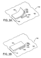
- FIGS 3A and 3B illustrate alternate embodiments of lockable microelectromechanical actuators according to the present invention. These embodiments illustrate lockable, out-of-plane, bimorph, cantilever thermal microelectromechanical actuators. It also will be understood that other microelectromechanical actuators including thermal, magnetic, electrostatic, in-plane and/or out-of-plane actuators may be provided.
- FIG 3A is a perspective view illustrating embodiments of bimorph cantilever actuators in an unlocked and open position and Figure 3B illustrates embodiments of bimorph cantilever beam thermal actuators in a locked and closed position.
- these embodiments of lockable thermal actuators 100 include a substrate 120 , such as a silicon semiconductor substrate, a support 140 and a cantilever beam 160 that comprises two bimorph materials 160a and 160b.
- the bimorph materials 160a and 160b are configured such that when the bimorph cantilever beam 160 is not heated, it remains in the open position shown in Figure 3A.
- a heater 240 may be provided to melt a thermoplastic material.
- the melted thermoplastic material is indicated in Figure 3A by 200'.
- the thermoplastic material 200' melts, and the cantilevered beam 160 is allowed to retract to its retracted or neutral position shown in Figure 3A.
- the cantilevered bimorph beam 160 is actuated by heating the cantilevered bimorph beam 160 , for example by passing current therethrough and/or by using an external heater. Power then is removed from the heater 240 , to allow the thermoplastic material 200 to solidify, thereby locking the bimorph cantilever beam 160 in its actuated position of Figure 3B. Simultaneously, or thereafter, heating of the cantilever bimorph beam 160b may be terminated, so that no additional power need be consumed. It may be desirable to provide a thermal isolator 260 between the cantilever bimorph beam and the thermoplastic material 200 , to thermally isolate the heated bimorph beam 160 from the heater 240.
- Thermal isolators 260 may comprise silicon dioxide, silicon nitride and/or other materials with relatively low thermal conductivity. Other thermal isolator structures also may be provided.
- Figure 4 is a top view of other embodiments of lockable thermal arched beam microelectromechanical actuators according to the present invention. These embodiments employ separate heaters to actuate the thermal actuator and to melt the thermoplastic material. By providing separate heaters, more accurate positioning of an actuator may be obtained.
- these embodiments of lockable thermal arched beam microelectromechanical actuators 1000 include a substrate 1200 , such as a silicon semiconductor substrate, spaced apart supports 1400a and 1400b on the substrate, and one or more arched beams 1600 that extend between the spaced apart supports 1400a and 1400b and that further arch upon application of heat thereto, for movement along the substrate in the direction shown by arrow 1800.
- a substrate 1200 such as a silicon semiconductor substrate
- spaced apart supports 1400a and 1400b on the substrate spaced apart supports 1400a and 1400b on the substrate
- one or more arched beams 1600 that extend between the spaced apart supports 1400a and 1400b and that further arch upon application of heat thereto, for movement along the substrate in the direction shown by arrow 1800.
- multiple arched beams 1600 are coupled via a coupler 2200.
- the thermal arched beams 1600 are heated by application of a voltage V 1 across a pair of terminals that are coupled to a heater 2800.
- Another heater 2400 may be mechanically coupled to the coupling member 2200 , so that it moves along with the coupling member 2200.
- the heater 2400 will be referred to herein as a first heater and the heater 2800 will be referred to herein as a second heater.
- a second voltage V 2 may be applied across the first heater 2400 using flexible wires 3200.
- the flexible wires 3200 also may provide mechanical stability for the actuator.
- the first heater 2400 may be directly on the substrate and need not move with the actuator.
- thermoplastic material 2000 is provided between the heater 2400 and the substrate 1200 .
- V 2 a voltage between the flexible wires 3200
- the thermoplastic material may be melted.
- An aperture 2400a may be provided in the heater 2400 , to allow the thermoplastic material to be placed between the heater 2400 and the substrate 1200 , by heating the heater 2400 and allowing the thermoplastic material to flow through the aperture 2400a , to between the heater 2400 and the substrate 1200 by capillary action.
- the thermoplastic material 2000 may be fabricated on the substrate 1200 prior to fabricating the beams 1600 , coupling member 2200 and heater 2400 above the substrate.
- an isolation member 3400 also may be provided.
- the isolation member 3400 can act as a mechanical shock absorber, and also can thermally isolate the first heater 2400 from the second heater 2200 , to allow independent control thereof.
- thermal isolation or additional thermal isolation may be provided by a low thermal conductivity member 3600 that is placed between the first heater 2400 and the second heater 2800.
- the low thermal conductivity member 3600 may comprise, for example, silicon dioxide and/or silicon nitride. Other thermal and/or mechanical isolators may be provided.
- a variable voltage V 1 may be applied to the second heater 2800 , to position the movable member 3800 while also applying sufficient voltage V 2 to the heater 2400 to melt the thermoplastic material 2000 . Then, when a desired position is obtained, the voltage V 2 may be withdrawn so that the thermoplastic material 2000 solidifies. The voltage V 1 then may be withdrawn from the heater 2800. Thus, retraction of the movable member 3800 may be prevented so that precise positioning may be obtained in a variable position device.
- the movable member also may be coupled to relay contacts, variable circuit elements such as variable resistors, capacitors and/or inductors, temperature reactive devices such as circuit breakers and/or other elements for actuation and positioning by embodiments of microelectromechanical actuators according to the present invention.
- variable circuit elements such as variable resistors, capacitors and/or inductors
- temperature reactive devices such as circuit breakers and/or other elements for actuation and positioning by embodiments of microelectromechanical actuators according to the present invention.
- thermoplastic material that is coupled to a microelectromechanical actuator to unlock the microelectromechanical actuator, and actuate the unlocked microelectromechanical actuator. Melting and actuating may take place simultaneously. The melted thermoplastic material then is allowed to solidify to lock the microelectromechanical actuator in an actuated position. The thermoplastic material then may be melted again to unlock and deactuate the microelectromechanical actuator.
- FIG. 5 is a timing diagram that illustrates actuation, retraction and locking of microelectromechanical actuators that use a single heater, such as embodiments of Figures 1A-2B.
- a first pulse P1 of a first power is applied to the heater 24.
- the power of pulse P1 preferably is sufficient to melt the thermoplastic material 20 and to actuate thermal arched beam 16 .
- a pulse P1 of 25 mA at 6 V for 10 ms may be applied.
- melting of the thermoplastic material 20 and actuation of the thermal arched beam 16 may occur simultaneously.
- the pulse P1 is terminated.
- the thermoplastic material solidifies and acts like a glue. As was described above, a small amount of retraction may take place until the thermoplastic material solidifies.
- a second pulse P2 is applied that is of lower power than the first pulse P1.
- pulse P2 has power that is sufficiently high to melt the thermoplastic material 20 , but is sufficiently low to prevent actuation of the actuator.
- the actuator is locked in the retracted position.
- thermoplastic material solidifies fast enough to lock the actuator in its new position.
- the actuator can be restored to its starting position by applying the pulse P2 that has enough heater power to melt the thermoplastic material but not enough to move the actuator. With the thermoplastic material melted, viscous flow can occur and permit the actuator to relax back to its neutral position.
- the time scale for the phase change transitions has been found to be compatible with the mechanical response of therrnal arched beam microelectromechanical actuators. This can provide a reversible system with continuous variability and allow a relatively simple control setup. Latching and unlatching may be accomplished by high and low power signals P1 and P1 respectively, across the same control inputs. Bistable operation thus may be achieved while allowing a simple control scheme. Reliability of at least 20,000 switch cycles presently has been obtained during testing, without degradation in electrical performance.
- Other thermoplastic materials may be selected to tailor the specific phase change temperature and the viscosity of the liquid phase according to device requirements.
- FIGS 6A and 6B are timing diagrams illustrating methods of operating microelectromechanical actuators that employ first and second heaters, such as the embodiments of Figure 4.
- a voltage pulse P1' is applied to terminal V 2 , to melt the thermoplastic material 2000 .
- a pulse P3' is applied to terminal V 1 to actuate the actuator to a desired position.
- the pulse P1' is terminated, to thereby solidify the thermoplastic material 2000.
- the pulse P3' then may be terminated.
- the pulses P1' and P3' are applied to separate heaters via separate terminals V 2 and V 1 , the pulses P1' and P3' may include a wide range of voltage, current and/or time parameters that need not be related to one another.
- a second pulse P2' may be applied to terminal V 2 , to again melt the thermoplastic material 2000 .
- This pulse may have a different voltage, current and/or power compared to pulse P1' or they may be identical, because pulse P2' can be independent of actuation of the actuator. High precision positioning thereby may be obtained.
Abstract
Description
- This invention relates to electromechanical systems, and more particularly to microelectromechanical systems and operating methods therefor.
- Microelectromechanical systems (MEMS) have been developed as alternatives to conventional electromechanical devices, such as relays, actuators, valves and sensors. MEMS devices are potentially low-cost devices, due to the use of microelectronic fabrication techniques. New functionality also may be provided, because MEMS devices can be much smaller than conventional electromechanical devices.
- Many applications of MEMS technology use MEMS actuators. These actuators may use one or more beams that are fixed at one or both ends. These actuators may be actuated electrostatically, magnetically, thermally and/or using other forms of energy.
- A major breakthrough in MEMS actuators is described in U.S. Patent 5,909,078 entitled Thermal Arched Beam Microelectromechanical Actuators to the present inventor et al., the disclosure of which is hereby incorporated herein by reference. Disclosed is a family of thermal arched beam microelectromechanical actuators that include an arched beam which extends between spaced apart supports on a microelectronic substrate. The arched beam expands upon application of heat thereto.
- Means are provided for applying heat to the arched beam to cause further arching of the beam as a result of thermal expansion thereof, to thereby cause displacement of the arched beam.
- Unexpectedly, when used as a microelectromechanical actuator, thermal expansion of the arched beam can create relatively large displacement and relatively large forces while consuming reasonable power. A coupler can be used to mechanically couple multiple arched beams. At least one compensating arched beam also can be included which is arched in a second direction opposite to the multiple arched beams and also is mechanically coupled to the coupler. The compensating arched beams can compensate for ambient temperature or other effects to allow for self-compensating actuators and sensors. Thermal arched beams can be used to provide actuators, relays, sensors, microvalves and other MEMS devices. Thermal arched beam microelectromechanical devices and associated fabrication methods also are described in U.S. Patent 5,955,817 to Dhuler et al. entitled Thermal Arched Beam Microelectromechanical Switching Array; U.S. Patent 5,962,949 to Dhuler et al. entitled Microelectromechanical Positioning Apparatus; U.S. Patent 5,994,816 to Dhuler et al. entitled Thermal Arched Beam Microelectromechanical Devices and Associated Fabrication Methods; and U.S. Patent 6,023,121 to Dhuler et al. entitled Thermal Arched Beam Microelectromechanical Structure, the disclosures of all of which are hereby incorporated herein by reference in their entirety.
- Unfortunately, conventional MEMS actuators may require continuous application of an electrostatic potential, a magnetic field, electric current and/or other energy to the MEMS actuator in order to maintain the actuator in a set or actuated position. This may consume excessive power. Moreover, an interruption of power may cause the actuator to reset.
- It is known to provide notches, dimples, protrusions, indentations and/or other mechanical features in MEMS actuators that can allow the actuator to be mechanically set in a given position. See for example, the above-cited U.S. Patents 5,955,817 and 5,994,816. Unfortunately, these mechanical features may be subject to wear. Moreover, mechanical locking that relies on friction may be difficult to obtain reliably due to the small dimensions of MEMS actuators and the uncertain values of static and dynamic friction in MEMS devices. Thus, notwithstanding conventional microelectromechanical devices, there continues to be a need for lockable microelectromechanical actuators that need not consume power when locked and need not rely on mechanical friction for locking.
- Lockable microelectromechanical actuators according to embodiments of the invention include a microelectromechanical actuator, a thermoplastic material that is coupled to the microelectromechanical actuator to lock the microelectromechanical actuator, and a heater that melts the thermoplastic material to allow movement of the microelectromechanical actuator. When the thermoplastic material solidifies, movement of the microelectromechanical actuator can be locked, without the need to maintain power, in the form of electric, magnetic and/or electrostatic energy, to the microelectromechanical actuator, and without the need to rely on mechanical friction to hold the microelectromechanical actuator in place. Thus, the thermoplastic material can act as a glue to hold structures in a particular position without the need for continuous power application. Moreover, it has been found unexpectedly, that the thermoplastic material can solidify rapidly enough to lock the microelectromechanical actuator at or near its most recent position.
- Embodiments of the present invention preferably are formed on a substrate, wherein the heater is on the substrate and wherein a portion of the microelectromechanical actuator is adjacent and spaced apart from the heater, and wherein the thermoplastic material is between the heater and the portion of the microelectromechanical actuator. The microelectromechanical actuators may move along the substrate to provide embodiments of "in-plane" microelectromechanical actuators. Alternatively, the actuators may move out of the plane of the substrate, for example, orthogonal to the substrate, to provide embodiments of "out-of-plane" microelectromechanical actuators.
- Embodiments of the present invention may be used with actuators that are actuated using electrostatic, magnetic, thermal and/or other forms of actuation. In embodiments of thermally actuated microelectromechanical actuators, the heater that melts the thermoplastic material also may be used to actuate the thermally actuated microelectromechanical actuator. In alternative embodiments, the heater that melts the thermoplastic material is a first heater and the lockable microelectromechanical actuator also includes a second heater that is thermally coupled to the microelectromechanical actuator, such that the microelectromechanical actuator moves in response to actuation of the second heater. Embodiments of lockable microelectromechanical actuators that employ first and second heaters also may include a thermal isolator that is configured to isolate the second heater from the thermoplastic material.
- In embodiments of the present invention that use the same heater to melt the thermoplastic material and to actuate the thermal actuator, the heater may be configured to melt the thermoplastic material and actuate the thermal actuator upon application of a first amount of power thereto. The heater also may be configured to melt the thermoplastic material without actuating the thermal actuator upon application of second amount of power thereto that is less than the first amount of power. Unexpectedly, it has been found that the actuator can be restored to its starting or unactuated position by applying sufficient power to the heater to melt the thermoplastic material, but not enough power to actuate the actuator. With the thermoplastic material melted, viscous flow can occur and permit the actuator to relax back to its neutral position. Thus, a reversible system may be provided, that can allow continuous variability and simple control setup.
- Thermoplastic materials according to the present invention may include thermoplastic polymers, thermoplastic monomers, solders and/or any other material that changes from a solid to a liquid material over a temperature range that is compatible with the ambient temperature in which the lockable microelectromechanical actuator will be used. Embodiments of lockable microelectromechanical actuators according to the invention may be combined with a relay contact, an optical attenuator, an optical switch, a variable circuit element such as a variable resistor, a valve, a circuit breaker and/or other elements to provide a microelectromechanical device.
- Other embodiments of the invention provide lockable thermal arched beam microelectromechanical actuators. Embodiments of thermal arched beam microelectromechanical actuators include a substrate, spaced apart supports on the substrate and an arched beam that extends between the spaced apart supports, and that further arches upon application of heat thereto for movement along the substrate. A thermoplastic material is coupled to the arched beam to lock the arched beam. A heater melts the thermoplastic material to allow movement of the arched beam. In preferred embodiments, the heater is on the substrate, the arched beam is adjacent and spaced apart from the heater, and the thermoplastic material is between the heater and the arched beam.
- Embodiments of lockable thermal arched beam microelectromechanical actuators use the heater both to further arch the arched beam and to melt the thermoplastic material. Alternative embodiments use a first heater to melt the thermoplastic material and a second heater that is thermally coupled to the arched beam to further arch the arched beam. These alternative embodiments also may include a thermal isolator that is configured to thermally isolate the second heater from the thermoplastic material.
- As was described above, in embodiments of lockable thermal arched microelectromechanical actuators wherein a single heater is used, the heater may be configured to melt the thermoplastic material and to further arch the arched beam upon application of a first amount of power thereto. The heater also may be configured to melt the thermoplastic material without further arching the arched beam upon application of a second amount of power thereto that is less than the first amount of power. Embodiments of lockable thermal arched beam microelectromechanical actuators can use the thermoplastic materials selected that were described above, and can be combined with other elements as was described above.
- Other embodiments of lockable thermal arched beam microelectromechanical actuators use first and second parallel arched beams that further arch upon application of heat thereto. A coupler is attached to the first and second arched beams, such that the first and second arched beams move in tandem along the substrate upon application of heat thereto. In these embodiments, the thermoplastic material may extend between the coupler and the heater. The coupler may include an aperture that extends therethrough from opposite the heater to adjacent the heater and that is configured to allow placement of the thermoplastic material between the coupler and the heater.
- Microelectromechanical actuators may be operated, according to embodiments of the present invention, by melting a thermoplastic material that is coupled to the microelectromechanical actuator to unlock the microelectromechanical actuator. The unlocked microelectromechanical actuator may be actuated. The melted thermoplastic material then may be allowed to solidify to lock the microelectromechanical actuator. In embodiments of these methods, the melting and actuating may be performed simultaneously. In other embodiments, melting of the thermoplastic material is performed by applying power to a heater that is thermally coupled to the thermoplastic material. The melted material is solidified by removing the power from the heater.
- In alternative embodiments of methods according to the present invention, the microelectromechanical actuator is a thermally actuated microelectromechanical actuator wherein the heater also is thermally coupled to the thermally actuated microelectromechanical actuator. Power is applied to the heater to actuate the thermally actuated microelectromechanical actuator. Melting and actuating may be performed simultaneously by applying power to the heater.
- In alternate embodiments of methods according to the present invention wherein the microelectromechanical actuator includes a first heater that is thermally coupled to the thermoplastic material and includes a second heater that is thermally coupled to the thermally actuated microelectromechanical actuator, melting may be performed by applying power to the first heater to melt the thermoplastic material. Actuating may be performed by applying power to the second heater, to actuate the thermally actuated microelectromechanical actuator. Power then may be removed from the heater, to allow the melted thermoplastic material to solidify.
- In all of the above method embodiments, the step of allowing the melted thermoplastic material to solidify may be followed by again melting the thermoplastic material to again unlock the microelectromechanical actuator. The microelectromechanical actuator then can return to its neutral or retracted position. Thus, by melting the thermoplastic material, the microelectromechanical actuator can be unlocked and deactuated.
- In embodiments of the present invention wherein a single heater also is used to thermally actuate the microelectromechanical actuator, the step of again melting the thermoplastic material may be performed by applying power to the heater that is sufficient to melt the thermoplastic material, but is insufficient to actuate the thermally actuated microelectromechanical actuator. The actuator thereby can deactuate or retract. In alternative embodiments wherein first and second heaters are used as described above, the step of again melting the thermoplastic material may be embodied by applying power to the first heater to melt the thermoplastic material without applying power to the second heater.
- Accordingly, lockable microelectromechanical actuators including lockable thermal arched beam microelectromechanical actuators, may be provided. These actuators need not consume power to remain actuated and need not rely on mechanical friction to maintain actuation. Thermoplastic materials also may be used to produce lockable large scale actuators that are not microelectromechanical actuators.
-
- Figure 1A is a perspective view of embodiments of lockable thermal arched beam microelectromechanical actuators according to the present invention in an unactuated position.
- Figure 2A is a side cross-sectional view along
line 2A-2A' of Figure 1A. - Figure 1B is a perspective view of embodiments of lockable thermal arched beam microelectromechanical actuators according to the present invention in an actuated position.
- Figure 2A is a side cross-sectional view along
line 2B-2B' of Figure 1B. - Figure 3A is a perspective view of other embodiments of lockable microelectromechanical actuators according to the present invention in an unlocked and open position.
- Figure 3B is a perspective view of other embodiments of lockable microelectromechanical actuators according to the present invention in a locked and closed position.
- Figure 4 is a top view of other embodiments of the lockable thermal arched beam microelectromechanical actuators according to the present invention.
- Figures 5, 6A and 6B are timing diagrams that illustrate embodiments of actuation, retraction and locking of microelectromechanical actuators according to the present invention
-
- The present invention now will be described more fully hereinafter with reference to the accompanying drawings, in which preferred embodiments of the invention are shown. This invention may, however, be embodied in many different forms and should not be construed as limited to the embodiments set forth herein; rather, these embodiments are provided so that this disclosure will be thorough and complete, and will fully convey the scope of the invention to those skilled in the art. In the drawings, the thickness of layers and regions are exaggerated for clarity. Like numbers refer to like elements throughout. It will be understood that when an element such as a layer, region or substrate is referred to as being "on", "connected to" or "coupled to" another element, it can be directly on, directly connected to or directly coupled to the other element, or intervening elements also may be present. In contrast, when an element is referred to as being "directly on", "directly connected to" or "directly coupled to" another element, there are no intervening elements present.
- Referring now to Figures 1A and 2A, a perspective view and a side cross-sectional view along
line 2A-2A' of first embodiments of lockable thermal arched beam microelectromechanical actuators according to the present invention in an unactuated, retracted or neutral position, are shown. As shown in Figures 1A and 2A, embodiments of lockable thermal archedmicroelectromechanical actuators 10 include asubstrate 12, such as a silicon semiconductor substrate, spaced apart supports 14a and 14b on the substrate, and one or morearched beams 16 that extend between the spaced apart supports 14a and 14b and that further arch upon application of heat thereto in the direction shown byarrow 18 for movement along thesubstrate 12. It will be understood that a singlearched beam 16 may be used. In alternative embodiments, a plurality ofarched beams 16, such as fourarched beams 16 in Figures 1A and 2A, may be used, that are coupled to common supports and/or individual supports. As used herein, any reference to a beam also shall include multiple beams, and any reference to multiple beams also shall include a single beam. A coupler may be attached to thearched beams 16, such that thearched beams 16 move in tandem along thesubstrate 12 upon application of heat thereto. As described in the above-cited U.S. Patents 5,909,078, 5,955,817, 5,962,949, 5,994,816 and 6,023,121, heat may be applied to thearched beams 16 by passing current through the beams and/or by an external heater. The design and operation of thermal arched beams as described in this paragraph are well known to those having skill in the art and need not be described further herein. - Still referring to Figures 1A and 2A, a
thermoplastic material 20 is coupled to thearched beam 16 to lock the arched beam. Aheater 24 also is provided that melts the thermoplastic material, to allow movement of the arched beam. Theheater 24 may be provided on thesubstrate 12 as illustrated. In other embodiments, the heater may be coupled to thearched beams 16 and/or thecoupler 22, to move with movement of these elements. - In preferred embodiments illustrated in Figure 1A, the
heater 24 is on thesubstrate 12, and thearched beams 16 are adjacent and spaced apart from the heater. The thermoplastic material is between the heater and the arched beams 16. More preferably, as shown in Figure 1A, the thermoplastic material is between thecoupler 22 and theheater 24. - The
thermoplastic material 20 may be formed between thecoupler 22 and theheater 24 by forming thethermoplastic material 20 on the heater prior to forming thecoupler 22 thereon. Alternatively, a solid thermoplastic material may be placed adjacent the gap (such as a 1µm gap) between theheater 24 and thecoupler 22 after fabrication of thecoupler 22. Theheater 24 then may be activated to melt thethermoplastic material 20, and allow it to creep between theheater 24 andcoupler 22 by capillary action. - As is well known to those having skill in the art, a thermoplastic material becomes soft (liquid) when heated and hard (solid) when cooled. Thermoplastic materials also may be referred to herein as Phase-Change Materials (PCM). Many thermoplastic materials are known to those having skill in the art and may be used in embodiments of the present invention. For example, a thermoplastic polymer may be used. An example of a thermoplastic polymer that may be used is Crystalbond™ 509, marketed by Aremco Products, Inc., Valley Cottage, NY. As described in the Aremco Products web site, www.aremco.com, Crystalbond™ 509 is a washaway adhesive that may be used to temporarily mount products that require dicing, polishing and/or other machining processes. These adhesives can exhibit high bond strength and adhere readily to metals, glass and ceramics. Crystalbond™ 509 has a flow point of 250°F (121°C) and a viscosity of 6000 cps. Another example of a thermoplastic polymer that may be used is polyethylene glycol, which is widely available in various molecular weights. As is known to those having skill in the art, the melting temperature of polyethylene glycol can be a function of the molecular weight, so that a variety of melting points may be selected for various applications. Thermoplastic monomers also may be used.
- The thermoplastic material preferably should be selected so that it remains in solid form in the range of ambient temperatures over which the microelectromechanical actuator may be used, yet can be melted at a temperature range that is slightly higher than the highest ambient temperature in which the microelectromechanical actuator may be used. The thermoplastic material preferably should melt over a narrow temperature range. The thermoplastic material also preferably should wet to the thermal
arched beam 16 and/or thecoupler 22 to which it is coupled. Thus, when the thermal arched beams and/or coupler are nickel, the thermoplastic material preferably should wet to nickel. The thermoplastic material also preferably should not wet to theheater 24 so that it can move with the thermal arched beam and/or coupler upon actuation thereof. Thus, when theheater 24 comprises polysilicon, the thermoplastic material preferably should not wet to polysilicon. - In higher temperature embodiments, solder may be used as a
thermoplastic material 20. For example, conventional lead-tin eutectic solder may have a melting point of about 240°C. Other thermoplastic materials may be used, depending upon the ambient temperature, the materials associated with the microelectromechanical actuator, and/or other factors. - Referring again to Figures 1A and 2A, embodiments of lockable arched beam microelectromechanical actuators are shown in their unactuated, neutral, return or retracted position. In this position, the
thermoplastic material 20 preferably is maintained in solid form by not applying heat thereto fromheater 24. Thus, chatter or other movement of theactuator 10 may be prevented. - Figures 1B and 2B are a perspective view and a side cross-sectional view along the
lines 2B-2B', of embodiments of lockable arched beam microelectromechanical actuators in a locked and actuated position. In order to actuate actuators of Figures 1A and 2A into the actuated position of Figures 1B and 2B, sufficient heat is applied toheater 24 to melt thethermoplastic material 20. Sufficient heat also is applied to thermalarched beams 16, to further arch thebeams 16 in thedirection 18 for movement along thesubstrate 12. This heat may be applied usingheater 24, using another external heater and/or by passing current through thebeams 16 themselves. The melted or plastic form of the thermoplastic material is designated 20' in Figures 1B and 2B, and is illustrated with a meniscus that is typical of a liquid material that is coupled between the surfaces of thecoupler 22 and theheater 24. - Upon removal of power from the
heater 24 while the actuator is actuated in the position shown in Figures 1B and 2B, the thermoplastic material solidifies, thus maintaining the actuator at or near its actuated position shown in Figures 1B and 2B. Thus, notwithstanding removal of power from theheater 24, from an external heater and/or termination of the current in the beam or beams 16, the actuator may remain at or near its actuated position. - Still referring to Figures 1A, 1B, 2A and 2B, when a
single heater 24 is used to both actuate the thermal arched beam microelectromechanical actuator and to melt thethermoplastic material 20, unexpected results may be obtained. A first unexpected result is that when power is removed from the heater, the thermoplastic material can solidify fast enough to lock the actuator in the actuated position shown in Figures 1B and 2B. A small amount of retraction may take place, but the thermoplastic material solidifies quickly enough so that the actuator remains at or near its most recent position shown in Figures 1B and 2B. In other to reduce or eliminate this small amount of retraction, current may be passed through a subset of the thermal arched beams in order to retain the thermal arched beams in the actuated position while the thermoplastic material solidifies. - Another unexpected result is that the actuator can be returned to or near its unactuated or neutral position of Figures 1A and 2A from its actuated position of Figures 1B and 2B, by applying sufficient heater current to
heater 24 to melt the thermoplastic material, but not enough current to thermally actuate the actuator. Thus, theheater 24 may be configured to melt thethermoplastic material 20 and actuate the thermal arched beam upon application of a first amount of power thereto, and to melt the thermoplastic material without actuating the thermal arched beam upon application of a second amount of power thereto that is less than the first amount of power. - In specific embodiments, it has been found that six volts and 25 mA may be applied to a
heater 24 for 10 ms to melt thethermoplastic material 20 and to actuate theactuator 10. Upon removal of this power, the thermoplastic material solidifies so that the actuator remains in its actuated position. Continuing with this embodiment, to reset the actuator, 15 mA may be applied to theheater 24 at 4V for about 15 ms. This power is sufficient to melt thethermoplastic material 20, but is insufficient to cause the thermal arched beam to remain actuated. Thus, the actuator may be restored. Upon removal of this power, the actuator may be maintained in its restored position when the thermoplastic material solidifies. - Figures 3A and 3B illustrate alternate embodiments of lockable microelectromechanical actuators according to the present invention. These embodiments illustrate lockable, out-of-plane, bimorph, cantilever thermal microelectromechanical actuators. It also will be understood that other microelectromechanical actuators including thermal, magnetic, electrostatic, in-plane and/or out-of-plane actuators may be provided.
- Figure 3A is a perspective view illustrating embodiments of bimorph cantilever actuators in an unlocked and open position and Figure 3B illustrates embodiments of bimorph cantilever beam thermal actuators in a locked and closed position. Referring to Figure 3A, these embodiments of lockable
thermal actuators 100 include asubstrate 120, such as a silicon semiconductor substrate, asupport 140 and acantilever beam 160 that comprises twobimorph materials bimorph materials bimorph cantilever beam 160 is not heated, it remains in the open position shown in Figure 3A. Aheater 240 may be provided to melt a thermoplastic material. The melted thermoplastic material is indicated in Figure 3A by 200'. Thus, upon application of heat to theheater 240, the thermoplastic material 200' melts, and thecantilevered beam 160 is allowed to retract to its retracted or neutral position shown in Figure 3A. - Referring now to Figure 3B, the cantilevered
bimorph beam 160 is actuated by heating the cantileveredbimorph beam 160, for example by passing current therethrough and/or by using an external heater. Power then is removed from theheater 240, to allow thethermoplastic material 200 to solidify, thereby locking thebimorph cantilever beam 160 in its actuated position of Figure 3B. Simultaneously, or thereafter, heating of thecantilever bimorph beam 160b may be terminated, so that no additional power need be consumed. It may be desirable to provide athermal isolator 260 between the cantilever bimorph beam and thethermoplastic material 200, to thermally isolate theheated bimorph beam 160 from theheater 240. Thus, when power is removed from theheater 240, the heating of thebeam 160 will not allow thethermoplastic material 200 to stay melted, but rather will allow thethermoplastic material 200 to solidify.Thermal isolators 260 may comprise silicon dioxide, silicon nitride and/or other materials with relatively low thermal conductivity. Other thermal isolator structures also may be provided. - Figure 4 is a top view of other embodiments of lockable thermal arched beam microelectromechanical actuators according to the present invention. These embodiments employ separate heaters to actuate the thermal actuator and to melt the thermoplastic material. By providing separate heaters, more accurate positioning of an actuator may be obtained.
- As shown in Figure 4, these embodiments of lockable thermal arched beam
microelectromechanical actuators 1000 include asubstrate 1200, such as a silicon semiconductor substrate, spaced apart supports 1400a and 1400b on the substrate, and one or morearched beams 1600 that extend between the spaced apart supports 1400a and 1400b and that further arch upon application of heat thereto, for movement along the substrate in the direction shown byarrow 1800. In Figure 4, multiplearched beams 1600 are coupled via acoupler 2200. The thermalarched beams 1600 are heated by application of a voltage V1 across a pair of terminals that are coupled to aheater 2800. - Another
heater 2400 may be mechanically coupled to thecoupling member 2200, so that it moves along with thecoupling member 2200. Theheater 2400 will be referred to herein as a first heater and theheater 2800 will be referred to herein as a second heater. A second voltage V2 may be applied across thefirst heater 2400 usingflexible wires 3200. Theflexible wires 3200 also may provide mechanical stability for the actuator. In alternative embodiments, thefirst heater 2400 may be directly on the substrate and need not move with the actuator. - A
thermoplastic material 2000 is provided between theheater 2400 and thesubstrate 1200. Upon application of a voltage V2 between theflexible wires 3200, the thermoplastic material may be melted. Anaperture 2400a may be provided in theheater 2400, to allow the thermoplastic material to be placed between theheater 2400 and thesubstrate 1200, by heating theheater 2400 and allowing the thermoplastic material to flow through theaperture 2400a, to between theheater 2400 and thesubstrate 1200 by capillary action. In alternative fabrication methods, thethermoplastic material 2000 may be fabricated on thesubstrate 1200 prior to fabricating thebeams 1600,coupling member 2200 andheater 2400 above the substrate. - Still referring to Figure 4, an
isolation member 3400 also may be provided. Theisolation member 3400 can act as a mechanical shock absorber, and also can thermally isolate thefirst heater 2400 from thesecond heater 2200, to allow independent control thereof. In alternative embodiments, thermal isolation or additional thermal isolation may be provided by a lowthermal conductivity member 3600 that is placed between thefirst heater 2400 and thesecond heater 2800. The lowthermal conductivity member 3600 may comprise, for example, silicon dioxide and/or silicon nitride. Other thermal and/or mechanical isolators may be provided. - Since two
separate heaters thermoplastic material 2000 and actuation of the thermalarched beams 1600 may be provided. Precise positioning of amovable member 3800 thereby may be provided. For example, as shown in Figure 4, an optical fiber and/or anaperture 4000 may be coupled to and/or formed in thesubstrate 1200. Precise positioning ofmovable member 3800 over the aperture/fiber 4000 may be provided, to thereby provide precise metering of a fluid and/or precise attenuation of optical energy. - In particular, a variable voltage V1 may be applied to the
second heater 2800, to position themovable member 3800 while also applying sufficient voltage V2 to theheater 2400 to melt thethermoplastic material 2000. Then, when a desired position is obtained, the voltage V2 may be withdrawn so that thethermoplastic material 2000 solidifies. The voltage V1 then may be withdrawn from theheater 2800. Thus, retraction of themovable member 3800 may be prevented so that precise positioning may be obtained in a variable position device. It will be understood that the movable member also may be coupled to relay contacts, variable circuit elements such as variable resistors, capacitors and/or inductors, temperature reactive devices such as circuit breakers and/or other elements for actuation and positioning by embodiments of microelectromechanical actuators according to the present invention. - Referring now to Figures 5, 6A and 6B, embodiments of methods of operating microelectromechanical actuators according to the present invention now will be described. In general, method embodiments of the present invention melt a thermoplastic material that is coupled to a microelectromechanical actuator to unlock the microelectromechanical actuator, and actuate the unlocked microelectromechanical actuator. Melting and actuating may take place simultaneously. The melted thermoplastic material then is allowed to solidify to lock the microelectromechanical actuator in an actuated position. The thermoplastic material then may be melted again to unlock and deactuate the microelectromechanical actuator.
- Figure 5 is a timing diagram that illustrates actuation, retraction and locking of microelectromechanical actuators that use a single heater, such as embodiments of Figures 1A-2B. As shown in Figure 5, in order to actuate the heater, a first pulse P1 of a first power is applied to the
heater 24. The power of pulse P1 preferably is sufficient to melt thethermoplastic material 20 and to actuate thermalarched beam 16. For example, a pulse P1 of 25 mA at 6 V for 10 ms may be applied. Thus, melting of thethermoplastic material 20 and actuation of the thermalarched beam 16 may occur simultaneously. Thereafter, to lock the actuator in the actuated position, the pulse P1 is terminated. The thermoplastic material solidifies and acts like a glue. As was described above, a small amount of retraction may take place until the thermoplastic material solidifies. - Continuing with the description of Figure 5, in order to retract the actuator, a second pulse P2 is applied that is of lower power than the first pulse P1. For example, 15 mA at 4V for 15 ms may be applied. Preferably, pulse P2 has power that is sufficiently high to melt the
thermoplastic material 20, but is sufficiently low to prevent actuation of the actuator. Upon removal of the lower power pulse P2, the actuator is locked in the retracted position. - A surprising and unexpected result is that when power is removed from the heater by terminating pulse P1, the thermoplastic material solidifies fast enough to lock the actuator in its new position. A further unexpected result is that the actuator can be restored to its starting position by applying the pulse P2 that has enough heater power to melt the thermoplastic material but not enough to move the actuator. With the thermoplastic material melted, viscous flow can occur and permit the actuator to relax back to its neutral position.
- The time scale for the phase change transitions has been found to be compatible with the mechanical response of therrnal arched beam microelectromechanical actuators. This can provide a reversible system with continuous variability and allow a relatively simple control setup. Latching and unlatching may be accomplished by high and low power signals P1 and P1 respectively, across the same control inputs. Bistable operation thus may be achieved while allowing a simple control scheme. Reliability of at least 20,000 switch cycles presently has been obtained during testing, without degradation in electrical performance. Other thermoplastic materials may be selected to tailor the specific phase change temperature and the viscosity of the liquid phase according to device requirements.
- Figures 6A and 6B are timing diagrams illustrating methods of operating microelectromechanical actuators that employ first and second heaters, such as the embodiments of Figure 4. As shown in Figures 6A and 6B, in order to actuate the actuator, a voltage pulse P1' is applied to terminal V2, to melt the
thermoplastic material 2000. After thethermoplastic material 2000 is melted, a pulse P3' is applied to terminal V1 to actuate the actuator to a desired position. When the actuator has reached its desired position, the pulse P1' is terminated, to thereby solidify thethermoplastic material 2000. The pulse P3' then may be terminated. It will be understood that since the pulses P1' and P3' are applied to separate heaters via separate terminals V2 and V1, the pulses P1' and P3' may include a wide range of voltage, current and/or time parameters that need not be related to one another. - Continuing with the description of Figures 6A and 6B, in order to retract the actuator, a second pulse P2' may be applied to terminal V2, to again melt the
thermoplastic material 2000. This pulse may have a different voltage, current and/or power compared to pulse P1' or they may be identical, because pulse P2' can be independent of actuation of the actuator. High precision positioning thereby may be obtained. - In the drawings and specification, there have been disclosed typical preferred embodiments of the invention and, although specific terms are employed, they are used in a generic and descriptive sense only and not for purposes of limitation, the scope of the invention being set forth in the following claims.
Claims (10)
- A lockable microelectrornechanical actuator including a microelectromechanical actuator (22), CHARACTERIZED BY:a thermoplastic material (20) that is coupled to the microelectromechanical actuator to lock the microelectromechanical actuator; anda heater (24) that is configured to melt the thermoplastic material to allow movement of the microelectromechanical actuator.
- A lockable microelectromechanical actuator according to Claim 1
CHARACTERIZED BY:
the microelectromechanical actuator being a thermally actuated microelectromechanical actuator that is configured to move in response to thermal actuation. - A lockable microelectromechanical actuator according to Claim 2 wherein the heater is a first heater (2400), the lockable microelectromechanical actuator further CHARACTERIZED BY a second heater (2800) that is thermally coupled to the microelectromechanical actuator such that the microelectromechanical actuator moves in response to actuation of the second heater.
- A lockable microelectromechanical actuator according to Claim 3 further CHARACTERIZED BY a thermal isolator (3400) that is configured to thermally isolate the second heater from the thermoplastic material.
- A lockable microelectromechanical actuator according to Claims 1, 2, 3 or 4 wherein the heater or first heater is further CHARACTERIZED BY being configured to melt the thermoplastic material and actuate the thermal actuator upon application of a first amount of power (P1) thereto and being configured to melt the thermoplastic material without actuating the thermal actuator upon application of a second amount of power (P2) thereto that is less than the first amount of power.
- A lockable microelectromechanical actuator according to Claims 1, 2, 3 or 4 further CHARACTERIZED BY at least one of a relay contact, an optical attenuator, an optical switch, a variable circuit element, a valve and a circuit breaker that is mechanically coupled to the microelectromechanical actuator for actuation thereby.
- A method of operating a microelectromechanical actuator
CHARACTERIZED BYmelting a thermoplastic material that is coupled to the microelectromechanical actuator to unlock the microelectromechanical actuator;actuating the unlocked microelectromechanical actuator; andallowing the melted thermoplastic material to solidify to lock the microelectromechanical actuator. - A method according to Claim 7 further CHARACTERIZED BY the steps of melting and actuating being performed simultaneously.
- A method according to Claims 7 or 8:wherein the microelectromechanical actuator is further CHARACTERIZED BY a heater that is thermally coupled to the thermoplastic material;wherein the melting step is further CHARACTERIZED BY the step of applying power to the heater to melt the thermoplastic material; andwherein the allowing step is further CHARACTERIZED BY the step of reducing the power to the heater to allow the melted thermoplastic material to solidify.
- A method according to Claims 7 or 8:wherein the microelectromechanical actuator is further CHARACTERIZED BY a first heater (2400) that is thermally coupled to the thermoplastic material;wherein the microelectromechanical actuator is a thermally actuated microelectromechanical actuator;wherein the microelectromechanical actuator is further CHARACTERIZED BY a second heater (2800) that is thermally coupled to the thermally actuated microelectromechanical actuator;wherein the melting step is further CHARACTERIZED BY the step of applying power to the first heater to melt the thermoplastic material;wherein the actuating step is further CHARACTERIZED BY the step of applying power to the second heater to actuate the thermally actuated microelectromechanical actuator; andwherein the allowing step is further CHARACTERIZED BY the step of reducing the power to the heater to allow the melted thermoplastic material to solidify.
Applications Claiming Priority (2)
| Application Number | Priority Date | Filing Date | Title |
|---|---|---|---|
| US543540 | 2000-04-05 | ||
| US09/543,540 US6367251B1 (en) | 2000-04-05 | 2000-04-05 | Lockable microelectromechanical actuators using thermoplastic material, and methods of operating same |
Publications (2)
| Publication Number | Publication Date |
|---|---|
| EP1143466A1 true EP1143466A1 (en) | 2001-10-10 |
| EP1143466B1 EP1143466B1 (en) | 2003-11-05 |
Family
ID=24168463
Family Applications (1)
| Application Number | Title | Priority Date | Filing Date |
|---|---|---|---|
| EP01302513A Expired - Lifetime EP1143466B1 (en) | 2000-04-05 | 2001-03-19 | Lockable microelectromechanical actuators using thermoplastic materials, and methods of operating same |
Country Status (7)
| Country | Link |
|---|---|
| US (1) | US6367251B1 (en) |
| EP (1) | EP1143466B1 (en) |
| KR (1) | KR20010095285A (en) |
| CN (1) | CN1316379A (en) |
| CA (1) | CA2340944A1 (en) |
| DE (1) | DE60101110T2 (en) |
| TW (1) | TW502002B (en) |
Cited By (2)
| Publication number | Priority date | Publication date | Assignee | Title |
|---|---|---|---|---|
| WO2006099065A2 (en) * | 2005-03-11 | 2006-09-21 | Massachusetts Institute Of Technology | Actuator array |
| WO2018108908A1 (en) * | 2016-12-14 | 2018-06-21 | Robert Bosch Gmbh | Electrically controllable adjustment device |
Families Citing this family (24)
| Publication number | Priority date | Publication date | Assignee | Title |
|---|---|---|---|---|
| US7064879B1 (en) * | 2000-04-07 | 2006-06-20 | Microsoft Corporation | Magnetically actuated microelectrochemical systems actuator |
| US6734597B1 (en) * | 2000-06-19 | 2004-05-11 | Brigham Young University | Thermomechanical in-plane microactuator |
| US6561479B1 (en) * | 2000-08-23 | 2003-05-13 | Micron Technology, Inc. | Small scale actuators and methods for their formation and use |
| US6775048B1 (en) * | 2000-10-31 | 2004-08-10 | Microsoft Corporation | Microelectrical mechanical structure (MEMS) optical modulator and optical display system |
| US6845959B2 (en) * | 2001-05-04 | 2005-01-25 | Hydril Company, L.P. | Quick release blowout preventer bonnet |
| US6690863B2 (en) * | 2001-05-17 | 2004-02-10 | Si Optical, Inc. | Waveguide coupler and method for making same |
| US20020170290A1 (en) * | 2001-05-18 | 2002-11-21 | Victor Bright | Multi-dimensional micro-electromechanical assemblies and method of making same |
| US6698201B1 (en) | 2001-08-16 | 2004-03-02 | Zyvex Corporation | Cascaded bimorph rotary actuator |
| US6664885B2 (en) * | 2001-08-31 | 2003-12-16 | Adc Telecommunications, Inc. | Thermally activated latch |
| WO2003041133A2 (en) * | 2001-11-09 | 2003-05-15 | Wispry, Inc. | Electrothermal self-latching mems switch and method |
| US7011288B1 (en) | 2001-12-05 | 2006-03-14 | Microstar Technologies Llc | Microelectromechanical device with perpendicular motion |
| US6804959B2 (en) * | 2001-12-31 | 2004-10-19 | Microsoft Corporation | Unilateral thermal buckle-beam actuator |
| US6624003B1 (en) * | 2002-02-06 | 2003-09-23 | Teravicta Technologies, Inc. | Integrated MEMS device and package |
| US7053519B2 (en) * | 2002-03-29 | 2006-05-30 | Microsoft Corporation | Electrostatic bimorph actuator |
| US6828887B2 (en) * | 2002-05-10 | 2004-12-07 | Jpmorgan Chase Bank | Bistable microelectromechanical system based structures, systems and methods |
| US6718764B1 (en) | 2002-06-28 | 2004-04-13 | Zyvex Corporation | System and method for microstructure positioning using metal yielding |
| JP4738720B2 (en) * | 2003-05-14 | 2011-08-03 | 古河スカイ株式会社 | Movable mechanism |
| US6985650B2 (en) * | 2003-08-05 | 2006-01-10 | Xerox Corporation | Thermal actuator and an optical waveguide switch including the same |
| US6983088B2 (en) * | 2003-08-05 | 2006-01-03 | Xerox Corporation | Thermal actuator and an optical waveguide switch including the same |
| US6985651B2 (en) * | 2003-08-05 | 2006-01-10 | Xerox Corporation | Thermal actuator with offset beam segment neutral axes and an optical waveguide switch including the same |
| DE112006000372T5 (en) * | 2005-02-19 | 2008-01-10 | General Motors Global Technology Operations, Inc., Detroit | Reconfigurable structures based on nodes of active material |
| US7602266B2 (en) * | 2007-03-16 | 2009-10-13 | Réseaux MEMS, Société en commandite | MEMS actuators and switches |
| SG176240A1 (en) | 2009-06-11 | 2012-01-30 | Agency Science Tech & Res | Microelectromechanical system (mems) device, method of operating the same, and method of forming the same |
| CN111446089B (en) * | 2020-03-12 | 2022-04-26 | 上海集成电路研发中心有限公司 | MEMS switch structure and manufacturing method |
Citations (2)
| Publication number | Priority date | Publication date | Assignee | Title |
|---|---|---|---|---|
| US4203086A (en) * | 1978-10-02 | 1980-05-13 | Illinois Tool Works Inc. | Temperature-sensitive spiral spring sliding contact device |
| US5994816A (en) * | 1996-12-16 | 1999-11-30 | Mcnc | Thermal arched beam microelectromechanical devices and associated fabrication methods |
Family Cites Families (4)
| Publication number | Priority date | Publication date | Assignee | Title |
|---|---|---|---|---|
| US5613861A (en) * | 1995-06-07 | 1997-03-25 | Xerox Corporation | Photolithographically patterned spring contact |
| US5962949A (en) | 1996-12-16 | 1999-10-05 | Mcnc | Microelectromechanical positioning apparatus |
| US5909078A (en) | 1996-12-16 | 1999-06-01 | Mcnc | Thermal arched beam microelectromechanical actuators |
| US5979892A (en) * | 1998-05-15 | 1999-11-09 | Xerox Corporation | Controlled cilia for object manipulation |
-
2000
- 2000-04-05 US US09/543,540 patent/US6367251B1/en not_active Expired - Fee Related
-
2001
- 2001-03-14 CA CA002340944A patent/CA2340944A1/en not_active Abandoned
- 2001-03-19 TW TW090106333A patent/TW502002B/en not_active IP Right Cessation
- 2001-03-19 DE DE60101110T patent/DE60101110T2/en not_active Expired - Fee Related
- 2001-03-19 EP EP01302513A patent/EP1143466B1/en not_active Expired - Lifetime
- 2001-04-03 KR KR1020010017746A patent/KR20010095285A/en not_active Application Discontinuation
- 2001-04-05 CN CN01116217A patent/CN1316379A/en active Pending
Patent Citations (2)
| Publication number | Priority date | Publication date | Assignee | Title |
|---|---|---|---|---|
| US4203086A (en) * | 1978-10-02 | 1980-05-13 | Illinois Tool Works Inc. | Temperature-sensitive spiral spring sliding contact device |
| US5994816A (en) * | 1996-12-16 | 1999-11-30 | Mcnc | Thermal arched beam microelectromechanical devices and associated fabrication methods |
Cited By (4)
| Publication number | Priority date | Publication date | Assignee | Title |
|---|---|---|---|---|
| WO2006099065A2 (en) * | 2005-03-11 | 2006-09-21 | Massachusetts Institute Of Technology | Actuator array |
| WO2006099065A3 (en) * | 2005-03-11 | 2007-01-11 | Massachusetts Inst Technology | Actuator array |
| US7665300B2 (en) | 2005-03-11 | 2010-02-23 | Massachusetts Institute Of Technology | Thin, flexible actuator array to produce complex shapes and force distributions |
| WO2018108908A1 (en) * | 2016-12-14 | 2018-06-21 | Robert Bosch Gmbh | Electrically controllable adjustment device |
Also Published As
| Publication number | Publication date |
|---|---|
| DE60101110D1 (en) | 2003-12-11 |
| KR20010095285A (en) | 2001-11-03 |
| TW502002B (en) | 2002-09-11 |
| EP1143466B1 (en) | 2003-11-05 |
| DE60101110T2 (en) | 2004-09-09 |
| CA2340944A1 (en) | 2001-10-05 |
| US6367251B1 (en) | 2002-04-09 |
| CN1316379A (en) | 2001-10-10 |
Similar Documents
| Publication | Publication Date | Title |
|---|---|---|
| EP1143466B1 (en) | Lockable microelectromechanical actuators using thermoplastic materials, and methods of operating same | |
| EP1143467B1 (en) | Microelectromechanical actuators including driven arched beams for mechanical advantage | |
| TW502003B (en) | Combination horizontal and vertical thermal actuator | |
| US6428173B1 (en) | Moveable microelectromechanical mirror structures and associated methods | |
| TW520340B (en) | Direct acting vertical thermal actuator with controlled bending | |
| WO2002088018A2 (en) | Multi-directional thermal actuator | |
| EP1121694B1 (en) | Microelectromechanical device having single crystalline components and metallic components and associated fabrication methods | |
| CA2332216A1 (en) | Actuators including serpentine arrangements of alternating actuating and opposing segments and related methods | |
| JP2001125014A (en) | Mems device attenuating light, variable light attenuating system, light attenuating method and manufacturing method of mems variable light attanuator. | |
| US6367252B1 (en) | Microelectromechanical actuators including sinuous beam structures | |
| CA2332219A1 (en) | Microelectromechanical devices having brake assemblies therein to control movement of optical shutters and other movable elements | |
| US6718764B1 (en) | System and method for microstructure positioning using metal yielding | |
| US6608714B2 (en) | Bi-directional, single material thermal actuator | |
| WO2009005683A1 (en) | A mems device with bi-directional element | |
| US6456190B1 (en) | Device for micromechanical switching of signals | |
| US8232858B1 (en) | Microelectromechanical (MEM) thermal actuator | |
| US6739132B2 (en) | Thermal micro-actuator based on selective electrical excitation | |
| Michael et al. | A novel bistable two-way actuated out-of-plane electrothermal microbridge | |
| US7944113B2 (en) | Hysteretic MEMS thermal device and method of manufacture | |
| JP2004530150A (en) | Bistable microactuator and optical switch | |
| Yi et al. | High-yield assembly of hinged 3D optical MEMS devices using magnetic actuation |
Legal Events
| Date | Code | Title | Description |
|---|---|---|---|
| PUAI | Public reference made under article 153(3) epc to a published international application that has entered the european phase |
Free format text: ORIGINAL CODE: 0009012 |
|
| AK | Designated contracting states |
Kind code of ref document: A1 Designated state(s): AT BE CH CY DE DK ES FI FR GB GR IE IT LI LU MC NL PT SE TR Kind code of ref document: A1 Designated state(s): CH DE FR GB LI |
|
| AX | Request for extension of the european patent |
Free format text: AL;LT;LV;MK;RO;SI |
|
| RAP1 | Party data changed (applicant data changed or rights of an application transferred) |
Owner name: JDS UNIPHASE CORPORATION |
|
| 17P | Request for examination filed |
Effective date: 20020410 |
|
| AKX | Designation fees paid |
Free format text: CH DE FR GB LI |
|
| GRAH | Despatch of communication of intention to grant a patent |
Free format text: ORIGINAL CODE: EPIDOS IGRA |
|
| RAP1 | Party data changed (applicant data changed or rights of an application transferred) |
Owner name: MEMSCAP S.A. |
|
| GRAH | Despatch of communication of intention to grant a patent |
Free format text: ORIGINAL CODE: EPIDOS IGRA |
|
| GRAA | (expected) grant |
Free format text: ORIGINAL CODE: 0009210 |
|
| AK | Designated contracting states |
Kind code of ref document: B1 Designated state(s): CH DE FR GB LI |
|
| REG | Reference to a national code |
Ref country code: GB Ref legal event code: FG4D |
|
| REG | Reference to a national code |
Ref country code: CH Ref legal event code: EP |
|
| REF | Corresponds to: |
Ref document number: 60101110 Country of ref document: DE Date of ref document: 20031211 Kind code of ref document: P |
|
| REG | Reference to a national code |
Ref country code: CH Ref legal event code: NV Representative=s name: CHRISTOPHE SAAM PATENTS & TECHNOLOGY SURVEYS SA |
|
| ET | Fr: translation filed | ||
| PLBE | No opposition filed within time limit |
Free format text: ORIGINAL CODE: 0009261 |
|
| STAA | Information on the status of an ep patent application or granted ep patent |
Free format text: STATUS: NO OPPOSITION FILED WITHIN TIME LIMIT |
|
| 26N | No opposition filed |
Effective date: 20040806 |
|
| PGFP | Annual fee paid to national office [announced via postgrant information from national office to epo] |
Ref country code: GB Payment date: 20050316 Year of fee payment: 5 |
|
| PGFP | Annual fee paid to national office [announced via postgrant information from national office to epo] |
Ref country code: DE Payment date: 20050317 Year of fee payment: 5 |
|
| PG25 | Lapsed in a contracting state [announced via postgrant information from national office to epo] |
Ref country code: LI Free format text: LAPSE BECAUSE OF NON-PAYMENT OF DUE FEES Effective date: 20050331 Ref country code: CH Free format text: LAPSE BECAUSE OF NON-PAYMENT OF DUE FEES Effective date: 20050331 |
|
| REG | Reference to a national code |
Ref country code: CH Ref legal event code: PL |
|
| PG25 | Lapsed in a contracting state [announced via postgrant information from national office to epo] |
Ref country code: GB Free format text: LAPSE BECAUSE OF NON-PAYMENT OF DUE FEES Effective date: 20060319 |
|
| PG25 | Lapsed in a contracting state [announced via postgrant information from national office to epo] |
Ref country code: DE Free format text: LAPSE BECAUSE OF NON-PAYMENT OF DUE FEES Effective date: 20061003 |
|
| GBPC | Gb: european patent ceased through non-payment of renewal fee |
Effective date: 20060319 |
|
| PGFP | Annual fee paid to national office [announced via postgrant information from national office to epo] |
Ref country code: FR Payment date: 20090331 Year of fee payment: 9 |
|
| REG | Reference to a national code |
Ref country code: FR Ref legal event code: ST Effective date: 20101130 |
|
| PG25 | Lapsed in a contracting state [announced via postgrant information from national office to epo] |
Ref country code: FR Free format text: LAPSE BECAUSE OF NON-PAYMENT OF DUE FEES Effective date: 20100331 |