EP1144965B1 - Spectrometer - Google Patents
Spectrometer Download PDFInfo
- Publication number
- EP1144965B1 EP1144965B1 EP00900491A EP00900491A EP1144965B1 EP 1144965 B1 EP1144965 B1 EP 1144965B1 EP 00900491 A EP00900491 A EP 00900491A EP 00900491 A EP00900491 A EP 00900491A EP 1144965 B1 EP1144965 B1 EP 1144965B1
- Authority
- EP
- European Patent Office
- Prior art keywords
- light
- spectrometer
- distance
- spot
- transparent body
- Prior art date
- Legal status (The legal status is an assumption and is not a legal conclusion. Google has not performed a legal analysis and makes no representation as to the accuracy of the status listed.)
- Expired - Lifetime
Links
- 230000003287 optical effect Effects 0.000 claims abstract description 42
- 230000003595 spectral effect Effects 0.000 claims abstract description 41
- 238000001514 detection method Methods 0.000 claims description 32
- 230000005540 biological transmission Effects 0.000 claims description 31
- 230000004075 alteration Effects 0.000 claims description 20
- 239000011358 absorbing material Substances 0.000 claims description 18
- 239000000463 material Substances 0.000 claims description 8
- 238000005286 illumination Methods 0.000 claims description 5
- 239000013307 optical fiber Substances 0.000 claims description 5
- 239000012780 transparent material Substances 0.000 claims description 5
- 238000001914 filtration Methods 0.000 claims description 2
- 230000010076 replication Effects 0.000 claims description 2
- 238000000034 method Methods 0.000 abstract description 22
- 238000005259 measurement Methods 0.000 description 36
- 238000009826 distribution Methods 0.000 description 14
- 230000009977 dual effect Effects 0.000 description 9
- 238000004088 simulation Methods 0.000 description 9
- 238000004519 manufacturing process Methods 0.000 description 7
- 238000012937 correction Methods 0.000 description 6
- 239000007787 solid Substances 0.000 description 6
- 238000007639 printing Methods 0.000 description 3
- 229910052724 xenon Inorganic materials 0.000 description 3
- FHNFHKCVQCLJFQ-UHFFFAOYSA-N xenon atom Chemical compound [Xe] FHNFHKCVQCLJFQ-UHFFFAOYSA-N 0.000 description 3
- 238000010420 art technique Methods 0.000 description 2
- 239000004568 cement Substances 0.000 description 2
- 239000011248 coating agent Substances 0.000 description 2
- 238000000576 coating method Methods 0.000 description 2
- 238000007516 diamond turning Methods 0.000 description 2
- 239000007789 gas Substances 0.000 description 2
- 239000011521 glass Substances 0.000 description 2
- 238000000227 grinding Methods 0.000 description 2
- 238000005498 polishing Methods 0.000 description 2
- 230000005855 radiation Effects 0.000 description 2
- 230000035945 sensitivity Effects 0.000 description 2
- UGFAIRIUMAVXCW-UHFFFAOYSA-N Carbon monoxide Chemical compound [O+]#[C-] UGFAIRIUMAVXCW-UHFFFAOYSA-N 0.000 description 1
- YZCKVEUIGOORGS-OUBTZVSYSA-N Deuterium Chemical compound [2H] YZCKVEUIGOORGS-OUBTZVSYSA-N 0.000 description 1
- 238000000149 argon plasma sintering Methods 0.000 description 1
- 238000003491 array Methods 0.000 description 1
- 230000007547 defect Effects 0.000 description 1
- 230000001419 dependent effect Effects 0.000 description 1
- 229910052805 deuterium Inorganic materials 0.000 description 1
- 238000006073 displacement reaction Methods 0.000 description 1
- 230000000694 effects Effects 0.000 description 1
- 238000004049 embossing Methods 0.000 description 1
- 238000005516 engineering process Methods 0.000 description 1
- 239000003292 glue Substances 0.000 description 1
- 229910052736 halogen Inorganic materials 0.000 description 1
- 150000002367 halogens Chemical class 0.000 description 1
- 239000007788 liquid Substances 0.000 description 1
- 230000007774 longterm Effects 0.000 description 1
- 230000007257 malfunction Effects 0.000 description 1
- -1 mercury-halide Chemical compound 0.000 description 1
- 229910001507 metal halide Inorganic materials 0.000 description 1
- 150000005309 metal halides Chemical class 0.000 description 1
- 238000000465 moulding Methods 0.000 description 1
- 239000005304 optical glass Substances 0.000 description 1
- 239000003973 paint Substances 0.000 description 1
- 230000001902 propagating effect Effects 0.000 description 1
- 241000894007 species Species 0.000 description 1
- 238000004611 spectroscopical analysis Methods 0.000 description 1
- 238000010183 spectrum analysis Methods 0.000 description 1
- WFKWXMTUELFFGS-UHFFFAOYSA-N tungsten Chemical compound [W] WFKWXMTUELFFGS-UHFFFAOYSA-N 0.000 description 1
- 229910052721 tungsten Inorganic materials 0.000 description 1
- 239000010937 tungsten Substances 0.000 description 1
- 238000000825 ultraviolet detection Methods 0.000 description 1
Images


Classifications
-
- G—PHYSICS
- G01—MEASURING; TESTING
- G01J—MEASUREMENT OF INTENSITY, VELOCITY, SPECTRAL CONTENT, POLARISATION, PHASE OR PULSE CHARACTERISTICS OF INFRARED, VISIBLE OR ULTRAVIOLET LIGHT; COLORIMETRY; RADIATION PYROMETRY
- G01J3/00—Spectrometry; Spectrophotometry; Monochromators; Measuring colours
-
- G—PHYSICS
- G01—MEASURING; TESTING
- G01J—MEASUREMENT OF INTENSITY, VELOCITY, SPECTRAL CONTENT, POLARISATION, PHASE OR PULSE CHARACTERISTICS OF INFRARED, VISIBLE OR ULTRAVIOLET LIGHT; COLORIMETRY; RADIATION PYROMETRY
- G01J3/00—Spectrometry; Spectrophotometry; Monochromators; Measuring colours
- G01J3/02—Details
- G01J3/0256—Compact construction
- G01J3/0259—Monolithic
-
- G—PHYSICS
- G01—MEASURING; TESTING
- G01J—MEASUREMENT OF INTENSITY, VELOCITY, SPECTRAL CONTENT, POLARISATION, PHASE OR PULSE CHARACTERISTICS OF INFRARED, VISIBLE OR ULTRAVIOLET LIGHT; COLORIMETRY; RADIATION PYROMETRY
- G01J3/00—Spectrometry; Spectrophotometry; Monochromators; Measuring colours
- G01J3/12—Generating the spectrum; Monochromators
- G01J3/18—Generating the spectrum; Monochromators using diffraction elements, e.g. grating
-
- G—PHYSICS
- G01—MEASURING; TESTING
- G01J—MEASUREMENT OF INTENSITY, VELOCITY, SPECTRAL CONTENT, POLARISATION, PHASE OR PULSE CHARACTERISTICS OF INFRARED, VISIBLE OR ULTRAVIOLET LIGHT; COLORIMETRY; RADIATION PYROMETRY
- G01J3/00—Spectrometry; Spectrophotometry; Monochromators; Measuring colours
- G01J3/28—Investigating the spectrum
- G01J3/2803—Investigating the spectrum using photoelectric array detector
-
- G—PHYSICS
- G01—MEASURING; TESTING
- G01J—MEASUREMENT OF INTENSITY, VELOCITY, SPECTRAL CONTENT, POLARISATION, PHASE OR PULSE CHARACTERISTICS OF INFRARED, VISIBLE OR ULTRAVIOLET LIGHT; COLORIMETRY; RADIATION PYROMETRY
- G01J3/00—Spectrometry; Spectrophotometry; Monochromators; Measuring colours
- G01J3/02—Details
- G01J3/0256—Compact construction
-
- G—PHYSICS
- G01—MEASURING; TESTING
- G01J—MEASUREMENT OF INTENSITY, VELOCITY, SPECTRAL CONTENT, POLARISATION, PHASE OR PULSE CHARACTERISTICS OF INFRARED, VISIBLE OR ULTRAVIOLET LIGHT; COLORIMETRY; RADIATION PYROMETRY
- G01J3/00—Spectrometry; Spectrophotometry; Monochromators; Measuring colours
- G01J3/02—Details
- G01J3/0278—Control or determination of height or angle information for sensors or receivers
-
- G—PHYSICS
- G01—MEASURING; TESTING
- G01J—MEASUREMENT OF INTENSITY, VELOCITY, SPECTRAL CONTENT, POLARISATION, PHASE OR PULSE CHARACTERISTICS OF INFRARED, VISIBLE OR ULTRAVIOLET LIGHT; COLORIMETRY; RADIATION PYROMETRY
- G01J3/00—Spectrometry; Spectrophotometry; Monochromators; Measuring colours
- G01J3/02—Details
- G01J3/0294—Multi-channel spectroscopy
Definitions
- the present invention relates to an apparatus and methods for measuring spectral information of light from at least one object.
- Spectroscopy is commonly practised with the use of cumbersome equipment comprising mirrors, lenses, and positioning equipment.
- monolithic spectrometers which are feasible for miniaturization, and less susceptible to misalignment, distortion, moisture, malfunction and other defects, have opened up for wider applications.
- Known monolithic spectrometers are generally unilateral-type spectrometers which are constructed so that the light entrance is positioned on the same side of the light propagating body as the light exits the body. This, however, limits the use of the spectrometers to applications wherein the detection means can be allowed to occupy space between the spectrometer and the object to be measured.
- An example of unilateral-type spectrometers is based on the Czerny-Turner configuration, which limits the minimum size of the compact spectrometer because of the required means for collimating the incoming light onto the diffraction means. Also, the Czerny-Turner configuration requires that entrance and detection means are placed on the same side of the spectrometer body.
- known monolithic spectrometers are rather simple. They consist of only one spectrometer channel, i.e. they can only measure one object at a time. Additionally, known monolithic spectrometers suffer from not being interference free, i.e. the measuring light contains spectral information from both the object and the reference light. This is a disadvantage in many practical situations where knowledge of the reference light is required to obtain precise spectral characteristics of the measured object. Either, the spectral characteristics of the reference light has to be known, or it has to be measured in the same spectrometer either prior to or immediately after measurements have been performed on the object measured. This method is both time consuming and can cause erroneous measurements if the reference light source varies over time.
- none of the prior art monolithic spectrometers include distance sensing means and consequently they are sensitive to variations in object distance.
- a unilateral-type spectrometer e.g. the Czerny-Turner configuration
- entrance means and detection means are placed on the same side of the spectrometer.
- US Application No. 4,770,530, Van Aken et al ., "Remote Spectrophotometer” discloses a non-compact spectrophotometer including means for directing reference light to a reference detector.
- a single detector is used to measure the integrated reference light. This embodiment does not provide a very precise reference measurement.
- the object and reference light are measured sequentially, which does not provide a precise reference measurement either, because the reference light might have changed.
- the object and reference light are directed to separate spectrometers, which is not a very cost effective solution. This illustrates why non-compact spectrometers do not provide multi-functionality nearly to the extent compact spectrometers do.
- Spectrometer discloses a non-monolithic spectrometer with two channels.
- the two channels are not exactly identical because they create different focus for different wavelengths.
- the measurements are performed on the object to be measured (here a gas, e.g. carbon monoxide) after the light has been dispersed by a diffractive grating, i.e. the object is not illuminated by polychromatic light.
- US Patent No. 4,707,138, Coatney, "Color Measuring and Control Device” discloses a color-detecting device. This prior art does not utilize a spectrometer, but monitor only two known wavelengths to obtain the color (spectral characteristics) of the object.
- the color sensor comprises a height detector to provide a signal indicating the distance between the object and color sensor. The height measurements are used to modify the color readings accordingly.
- the sensor is not compact, neither is the distance sensing means an integrated part of the color sensor, but a separate unit.
- an apparatus for measuring spectral information of light from at least one object comprising at least one light detecting means; and at least one transparent body having a front side and a back side; said front side including:
- the arrangement of the at least one diffractive element and the at least one focusing means so that the transmitted light is diffracted before being focused ensures that compensation or reduction of aberration, in particular chromatic aberration can easily be obtained.
- Compensation or reduction of aberration can be obtained in any suitable manner involving aberration correcting means under or after the focusing process.
- the apparatus further comprises aberration correcting means.
- the aberration correcting means comprises that the at least one focusing means is aspheric whereby the wavelength dependent reflection by the aspheric focusing means is used to correct the diffracted light of various wavelengths to the desired focus.
- the aberration correcting means comprises tilting a planar exit surface or providing an aspheric exit surface whereby the diffracted light focused by the focusing means is refracted to the desired focus.
- the aberration correcting means comprises a combination of the at least one focusing means being aspheric and the exit surface being tilted whereby the aberration compensation or reduction can be made more effective.
- light detecting means are separated from the entrance aperture means, whereby the apparatus can be positioned in a flexible manner with respect to the object(s) to be measured. That is, the apparatus can be positioned very close to one or more objects. This is e.g. particularly useful for applications of compact spectrometers to color measurements in printing machines.
- the front side includes at least one further reflecting surface; and the said back side includes at least one further reflecting surface; said further reflecting surfaces being arranged to reflect light more times before being received by the at least one focusing means, the at least one diffractive means, or both whereby the light path can be increased and consequently the resolution can be increased.
- the light from the object to be measured enters the spectrometer through an entrance aperture means.
- the aperture means serves to achieve a suitable resolution of the spectrometer.
- the entrance aperture means comprises of a rectangular slit, but the light might also be provided through optical waveguide means, in particular optical fiber means, or through other appropriate aperture means, thereby ensuring a desired resolution of the spectrometer and a suitable reception of light.
- the entrance aperture means further comprises a wavelength bandpass filter whereby it is achieved that the spectrometer only analyzes a desired wavelength bandwidth of light, which is particularly useful in order to optimize the signal-to-noise ratio.
- the at least one diffractive optical element is preferably planar or aspheric whereby it can easily be adapted to said at least one reflecting surfaces of the front and back sides depending on their particular function.
- the diffractive optical element is a blazed grating whereby an improved efficiency of the spectrometer is achieved, said efficiency being defined as the amount of light distributed across the light detecting means compared to the amount of light entering the entrance aperture means.
- the at least one focusing means is preferably an aspheric surface, whereby it is achieved that the optics design of a compact spectrometer can be realized with fewer aberrations.
- the term "aspheric surface” is known in the art, see e.g. ZEMAX, Optical Design Program, User's Guide Version 7.0, Focus Software, Inc., Arlington, AZ (1998) p. 13-4.
- a spherical surface which is commonly used in many standard lenses, is a specie of an aspheric surface.
- aberrations is intended to designate the various forms of aberration, e.g. spherical and chromatic aberration, known in the art, e.g., see E. Hecht, “Optics,” Addison-Welsey, 1987, Section 6.3.
- the light detecting means can be positioned either in or near the exit surface of the transparent body of the apparatus, e.g. compact spectrometer, or it can be positioned at a distance from the exit surface.
- a very rugged spectrometer is achieved, which is advantageous in many applications where the spectrometer might be subject to vibrations during its use. Also it is advantageous with respect to long term stability of the spectrometer.
- the light detection means may be positioned below or above the surface of the exit surface face of the back side of the transparent body. In a preferred embodiment the detection means is positioned below the surface of the exit surface thereby ensuring a more robust spectrometer with less sensitivity of having the components in or near the surface of exit face destroyed by external strikes or the like to the body.
- the light detecting means comprises an array detector, whereby it is achieved that each element of the array detector corresponds to either a single wavelength or a narrow bandwidth of wavelengths.
- each element of the array detector corresponds to either a single wavelength or a narrow bandwidth of wavelengths.
- the light detection means further comprises a wavelength bandpass filter, whereby it is achieved that the light detection means only analyzes the desired wavelength bandwidth of light which is particularly useful in order to optimize the signal-to-noise ratio.
- the transparent body is a unitary body or a composed body.
- the unitary or composed body is replicated in optical plastic material, e.g. by embossing or molding, whereby it is possible to mass-produce e.g. a very cheap compact spectrometer.
- the unitary or composed body is replicated such that the reflective surfaces are positioned below the respective surfaces of the front side and back side thereof.
- This embodiment is particularly advantageous, because the final spectrometer exhibits a box shape with parallel outer surfaces.
- the transparent body is a composed body comprising a front part, a back part, and optionally an intermediate part; said front part incorporating said entrance aperture means, said at least one diffractive optical element and/or said at least one focusing means; and said back part incorporating said exit surface, said at least one diffractive optical element and/or said at least one focusing means.
- the intermediate part may be present or not depending on the application.
- said optionally intermediate part consists of a material selected from the group consisting of a low cost transparent material, a thermally stable transparent material, and a filtering material, or a combination thereof.
- the parts of the composed body might be coupled by e.g. optical cement.
- the unitary or composed body might also be assembled by single pieces of optical elements, e.g. replicated optical elements or glass optical elements, which are coupled with e.g. optical cement.
- the transparent body is preferably covered with light absorbing material, e.g., black paint, apart from apertures necessary for light passage, e.g. the entrance aperture means and at the exit surface.
- the light absorbing material serves to suppress stray light, i.e. to suppress multiple scattered light inside the transparent body that adds noise to the measurements.
- the light absorbing material further serves to prevent ambient light to enter the spectrometer and thus add noise to the measurements. Additionally it serves to prevent light from the entrance aperture means to be guided directly to the light detection means, which is possible in a transmission spectrometer, and crucial for the measurements because this effect cannot easily be eliminated electronically.
- Imperfections in the diffractive optical element is causing a substantian amount of stray light in all spectrometers.
- the light absorbing material has an index of refraction identical to or very close to the index of refraction of the spectrometer unit, whereby reflections from the interface between said light absorbing material and said spectrometer body is minimized.
- the amount of stray light is further suppressed.
- the light absorbing material is also molded into said body.
- the light absorbing material is coated, e.g. painted, onto said transparent body.
- the transparent body is a composed body
- light absorbing material is positioned inside the composed body, e.g. between the composed units, whereby it is possible to further suppress the amount of stray light and eliminate light scattering directly from the entrance aperture means to the light detection means, because extra sets of apertures can be included.
- the apparatus comprises at least two spectrometer channels, e.g. a multi-channel spectrometer comprising at least two transparent bodies, each of which constitutes said channels.
- the multi-channel spectrometer might be realized by positioning the channels in parallel, but the channels can also be placed in continuation of each other in a so-called serial spectrometer.
- the light detection means preferably comprises of an array sensor with a separate array for each channel.
- the different channels illuminate separate parts of the single-array detector.
- the advantage of the parallel multi-channel spectrometer is that the sensitivity can be adjusted separately for each channel at the cost of constructing extra electronics.
- the apparatus e.g. either the transmission spectrometer or the multi-channel spectrometer, further comprises at least one reference light source arranged to illuminate the object.
- the object can be illuminated either in a reflection or a transmission mode, which is further described below.
- the illuminating light can be guided to the object either by free space propagation, e.g. combined with lens arrangements, or via light guiding means, e.g. an optical fiber.
- the object is illuminated in a reflection mode, here defined as a mode wherein the object is illuminated on the side facing the spectrometer, i.e. light scattered off or reflected from the object is received by the entrance aperture means of the apparatus.
- Typical objects illuminated in reflection mode comprise objects that are not transparent to the wavelength bandwidth of the illuminating light, e.g. non-transparent solid surfaces such as printing paper.
- the object is illuminated in a transmission mode, here defined as a mode wherein the object is illuminated on the side not facing the spectrometer, i.e. light transmitted through the object is received by the entrance aperture means of the apparatus.
- Typical objects illuminated in transmission mode comprise of objects that are transparent to the wavelength bandwidth of the illuminating light, e.g. transparent gases or liquids.
- the at least one reference light source should emit polychromatic light in a wavelength range suitable for the application.
- the at least one reference light source is a continuous light source or a flash-type light source, preferably a white-light LED or a xenon lamp of either the continuous type or flash type.
- lamps are tungsten, metal-halide such as mercury-halide, halogen or deuterium lamps.
- Ambient light can also be used as light source, e.g. sunlight.
- a series of narrow-bandwidth light sources can also be used.
- a series of LED's is used, where the individual wavelength bandwidths overlap and consequently creates polychromatic light.
- part of the illuminating light is guided to the entrance of at least one of the spectrometer channels via light guiding means or via free space propagation.
- This channel is here defined as the reference channel.
- said transparent body comprises at least one measuring part for measuring light from the object and a reference part for measuring light from the at least one reference light source whereby the measurement is independent of variations in the reference light.
- At least one spectrometer channel is used to analyze light from the at least one object whereas another spectrometer channel, the reference channel, is used to simultaneously analyze the spectral distribution and intensity of the reference light source used to illuminate the object to be analyzed.
- This configuration is particularly advantageous because simultaneous readout of reference light source and object provides a means for rapid and more accurate measurements. Additionally, simultaneous measurements of object and reference light make the measurements insensitive to any variation in the reference light used to illuminate the object.
- the spectrometer channel used to monitor the reference light can be illuminated with part of the reference light either via optical fiber means or other waveguiding means.
- a special base plate is used to guide part of the reference light to the reference channel.
- the apparatus further comprises means for removing the spectral influence of the reference light in the light measured from the object.
- the reference light correcting means communicate with the light detection means.
- object light is measured independent of variations in the reference light.
- Typical reference light correcting means comprise computing means for determining light intensities of both object light and reference light and calibration procedures including corrections for cross interferences in both channels.
- the ratio of the signal entering the reference channel to the ratio illuminating the object is known, and the reference light correcting means simply accounts for the ratio and subtracts the reference light from the object light.
- the spectrometer undergoes a first calibration with a calibration object, where after the changes of the reference light is monitored in the reference channel.
- the reference light correcting means then corrects for the changes in the reference light compared with the reading of reference light taken at the calibration.
- the apparatus further comprises a light spot source for illuminating a light spot onto the object; and a distance sensing means for measuring the distance between the object and said entrance aperture means, whereby the spectral information of the object is measured independent of variations in the object distance.
- any of the spectrometer geometry's described above can include distance sensing means, but in a preferred embodiment, the distance sensing means is combined with a transmission spectrometer, whereby the distance sensing means can reuse the spectral sensing means.
- the distance sensing means is combined with a multi-channel spectrometer, where at least one channel is used as reference channel.
- the distance sensing means includes a light spot source for illuminating a light spot onto the object.
- the light spot source comprises of a monochromatic light source, e.g. a laser diode, or a source with limited wavelength bandwidth, e.g. an LED.
- the distance sensing means includes means for focusing the light spot on the object onto the spot detection means.
- the focusing means can either be a refractive optical element, e.g. a lens, or a diffractive optical element.
- the focusing means further comprises a wavelength bandpass filter allowing only passage of the light within the bandwidth of the light spot source.
- a wavelength bandpass filter allowing only passage of the light within the bandwidth of the light spot source.
- the spot detecting means is an array detector or a position sensitive detector.
- the spot detecting means is the same as the light detecting means, whereby is achieved that the spectral measurement is performed simultaneously with the distance sensing.
- This geometry is particularly advantageous when the distance sensing means is combined with a transmission spectrometer.
- either the spot size or the spot position is determined on the spot detection means.
- the object distance is determined by geometrical magnification, whereas in another preferred embodiment, the object distance is determined by triangulation. Both methods are well known in the art.
- the apparatus further comprises means for removing the influence of the object distance in the light measured from the object.
- the object distance correcting means communicate with the spot detection means.
- object light is measured independent of variations in object distance.
- the changes in object light intensity entering the spectrometer caused by changing object distance is known, and the object distance correcting means simply accounts for the changes when the object distance is known.
- the distance sensing means is combined with a multi-channel spectrometer in which at least one channel is used as reference channel.
- the spectrometer undergoes a first calibration with a calibration object, where the received object intensity is measured at fixed object distances.
- the distance correcting means is correcting here fore.
- the present invention provides an apparatus for measuring spectral information of light from at least one object; said apparatus comprising at least one light detecting means; and at least one transparent body including:
- This apparatus still has the advantage of being compact and easy to position with respect to the objects. It is however not limited to the transmission configuration whereby entrance aperture means and detecting means may be positioned on the same face of the transparent body.
- the several parts for measuring light from several objects comprise at least one measuring part for measuring light from one or more objects and a reference part for measuring light from a reference light source.
- the present invention provides an apparatus for measuring spectral information of light from at least one object; said apparatus comprising at least one light detecting means; at least one light spot source for illuminating a light spot onto the at least one object; and at least one transparent body; said body including:
- This apparatus has the advantage of correcting for influences of distance variations from the apparatus to the at least one object.
- the present invention provides an apparatus for measuring spectral information of light from at least one object; said apparatus comprising at least one light detecting means; at least one light spot source for illuminating a light spot onto the at least one object; at least one transparent body including:
- the at least two transparent bodies comprise at least one measuring part for measuring light from one or more objects and a reference body for measuring light from a reference light source.
- this apparatus has the advantage of correcting for influences of distance variations to the object or objects. This is particularly advantageous since multi-channel spectrometers generally do not include this correction.
- the present invention provides an apparatus for measuring spectral information of light from at least one object; said method comprising:
- the spectral influence of the reference light in the object light is removed by subtracting the measured reference light from the measured object light.
- the spectral influence of the reference light in the object light is removed by correcting for changes in the reference light compared to a reference measurement taken at a first calibration.
- the method further comprising the steps of:
- the object is illuminated by flash type illumination means, e.g. a xenon flash tube, the object light vary from flash to flash.
- flash type illumination means e.g. a xenon flash tube
- the present invention provides an apparatus for measuring spectral information of light from at least one object; said method comprising:
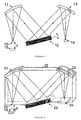
- a source 10 of light is typically a slit or an aperture illuminated by light from an object 15 positioned at a distance d therefrom.
- Light from the source passes to a first parabolic mirror 11, which produces and directs a plane wave towards a diffractive means 12, e.g. grating.
- the diffracted plane wave is collected by a second parabolic mirror 13, which reflects the light and focuses an image of the source onto a detector 14. Since the angle of diffraction of the light from the diffractive means varies with wavelength, the spectrometer effectively produces an infinite number of images, each at different wavelength, spread across the plane of the detecting means.
- the relative alignment of the slit, mirrors, grating, and detector is crucial to the reliability of the spectrometer.
- the detector can only measure one wavelength at a time. Consequently, measurement of other wavelengths or the bandwidth of a spectral line requires physical movement of the grating.
- spectrometers using linear detector arrays can measure simultaneously the intensities at multiple wavelengths. Consequently, no moving parts are necessary in the spectrometer.
- the optical layout of a typical prior art compact, monolithic spectrometer 25 is shown in Fig. 2.
- a source 20 of light is typically a slit or aperture illuminated by light from an object 15 positioned at a distance d therefrom.
- Light from the source passes to a first parabolic mirror 21, which produces and directs a plane wave towards a diffraction grating 22.
- the diffracted plane wave is collected by a second parabolic mirror 23 which reflects the light and focuses an image of the source onto a linear detector array 24. Since the angle of diffraction of the light from the diffraction grating varies with wavelength, the spectrometer effectively produces an infinite number of images, each at different wavelength, spread across the plane of the detector.
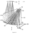
- Fig. 3 shows a cross-sectional sketch of a ray-tracing simulation of a single channel including a transparent body 31 in a preferred transmission spectrometer embodiment.
- a light source 38 illuminates the object 15 positioned in front F of the transparent body 31.
- the object is positioned the distance d from the entrance aperture means 30, positioned at the entrance surface 311.
- the entrance aperture means comprises of a rectangular slit.
- a diffractive optical element 32 here a blazed grating
- diffracts the light towards a reflective surface 312 of the front side in this preferred embodiment an aspheric mirror 33.
- the aspheric mirror focuses the diffracted wavelengths across the plane of the light detecting means 34, in this example comprising of an array detector and placed opposite the entrance means at the back side B of the transparent body.
- the light detecting means is placed at a distance from the exit surface 314, which is tilted to correct for chromatic aberrations.
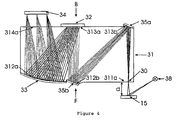
- Fig. 4 shows a cross-sectional sketch of a ray-tracing simulation of a single channel including a transparent body 31 in a preferred transmission spectrometer embodiment.
- a light source 38 illuminates the object 15 positioned in front F of the transparent body 31.
- the object is positioned the distance d from the entrance aperture means 30, positioned at the entrance surface 311a.
- the entrance aperture means comprises of a rectangular slit.
- the light propagates towards a further reflecting surface 313b of the back side at which a planar mirror 35a directs the light towards a further reflective surface 312b of the front side at which a planar mirror 35b directs the light towards the reflective surface 313a of the back side, at which a diffractive optical element 32 (here a blazed grating) diffracts the light towards the reflective surface 312a of the front side, in this preferred embodiment an aspheric mirror 33.
- the aspheric mirror focuses the diffracted wavelengths across the plane of the light detecting means 34, in this example comprising of an array detector and placed opposite the entrance means at the back side B of the transparent body.
- the light detecting means is placed at a distance from the exit surface 314a.
- the diffractive optical element 32 and the detecting means 34 are arranged in parallel planes or coinciding planes. Also, the entrance surface 311a and the exit surface 314a are parallel.
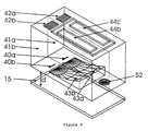
- Fig. 5A shows a three dimensional sketch of a preferred embodiment in which the reflective surfaces (i.e., the planar mirrors 35a, 35b, the diffractive optical element 32, and the aspheric mirror 33) are positioned below the respective surfaces of the front side and back side.
- Fig. 5B shows a cross-sectional sketch taken at the plane C from Fig. 5A.
- Fig. 6 shows a three dimensional sketch of a preferred embodiment in which the spectrometer body is a composed body (31a, 31b) and in which light absorbing material 315 is placed between said composed bodies.
- the spectrometer is similar to the transmission spectrometer illustrated in Fig. 5 and described above.
- the composed body comprising a front part 31a and a back part 31b.
- the front part is incorporating an entrance aperture means 30, a further planar mirror 35b, and the focusing means 33.
- the back part is incorporating a further planar mirror 35a, the diffractive optical element, and the exit surface.
- This preferred embodiment is composed of two parts (31a, 31b).
- the transparent composed body further comprises an intermediate part.
- Fig. 7 shows a three dimensional sketch of a preferred embodiment that consists of two parallel spectrometer channels.
- the dual channel spectrometer comprises of a measurement channel 41a to measure light from the object 15 and a reference channel 41b to measure light from the reference light source 38 (not shown in Fig. 7).
- the light enters each spectrometer channel through an aperture, in this example rectangular slits (40a, 40b), and each channel is an independent transmission spectrometer working according to the ray-tracing simulation illustrated in Fig.3 with the exception that that the aspheric mirrors (43a, 43b) now focus the diffracted wavelengths across the detecting means (44a, 44b) which is now positioned at the exit surface.
- the light from the measurement channel 41a is focused onto the light detecting means 44a whereas the light from the reference channel is focused onto the light detecting means 44b.
- the detecting means (44a, 44b) comprises of a dual line sensor, said line comprising of an array sensor.
- the array sensor is a dual line sensor of 2x256 pixels (S4801-256Q), from Hamamatsu Photonics, JP.
- Example 1 An illustration of simultaneous measurement of object light and reference light is shown in Example 1.
- Fig. 8 shows a three dimensional sketch of a preferred embodiment in which one spectrometer channel 31 is combined with a distance sensing means.
- the spectrometer channel is similar to the transmission spectrometer illustrated in Fig. 7 and described above.
- the distance sensing means preferably comprises of a light spot source 51 for focusing a light spot 53 onto said object 15.
- a focusing means 52 is integrated within the compact spectrometer unit 31 and focuses the light spot from the object onto said spct detecting means 44c.
- the light detecting means and the spot detecting means is combined in a single detecting means 44c.
- the light spot source 51 illuminates the object 15 under an angle. If the object distance is changed, the position of the illuminated light spot on the spot detecting means 44c is displaced in the longitudinal direction of the detecting means. I.e., the object distance is determined by triangulation.
- Example 2 An illustration of simultaneous measurement of object light - and - spot position for two different object distances is shown in Example 2.
- Fig. 9 shows a three dimensional sketch of another preferred embodiment in which a dual channel spectrometer is combined with a distance sensing means. That is a combination of the preferred embodiments illustrated in Figs. 7 and 8 respectively.
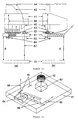
- Figure 10 shows another cross-sectional sketch of a preferred embodiment in which a dual channel spectrometer is combined with a distance sensing means.
- This embodiment has been used for the examples described below, and includes additionally a base plate 61 that guides part of the reference light 68 to the reference channel. Additionally, the base plate contains the focusing means 62 for the distance sensing means.
- the base plate 61, spectrometer unit 41, and detecting means 44 are aligned with respect to each other in a specially fabricated box (not shown here).
- FIG. 11 A three dimensional sketch of the base plate 61 is illustrated in Fig. 11. Part of the reference light used to illuminate the object enters the base plate 61 via an entrance aperture 65.
- a double-sided mirror coating 66 ensures that the light is multiple reflected (see the illustration of the light rays 68 in Figs. 10 and 11) to a prism with a mirror coating 64.
- the mirror 64 ensures that the reference light is reflected through the entrance aperture means 60 (here placed on the base plate 61) into the spectrometer reference channel.
- the base plate 61 contains the focusing means 62 for the distance sensing means.
- a wavelength bandpass filter 63 allowing only the narrow wavelength bandwidth of the light spot source (not shown here) for the distance sensing means to be transmitted.
- a ray trace of the light for the distance sensing means 67 is shown in Fig. 10.
- a prism 45 is used to bend the focused light for the distance sensing means to the same detection means 44 as is used to analyze the light from the object.
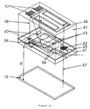
- Fig. 12 shows a three dimensional sketch of another preferred embodiment in which a dual channel spectrometer is combined with a distance sensing means.
- This preferred embodiment is a planar version of the embodiment illustrated in Figs. 10 and 11.
- all reflective surfaces are placed below the respective faces of the front side and back side of the spectrometer and the base plate.
- Fig. 10 An apparatus according to the one shown in Fig. 10 was provided where the object was illuminated by a reference light source at an angle of 45 degrees.
- the object was a calibrated white tile from NPL, UK.
- the object distance d was 15 mm and the object was illuminated with a xenon light source.
- the signals are read from the two channels in the array sensor (S4801-256 from Hamamatsu Photonics, JP).
- Fig. 13 shows the intensity I in arbitrary units versus pixel number N.
- the solid line S represents the spectral distribution of the reference light source and the dashed line D represents the spectral distribution read from the white object.
- the pixel numbers are converted to wavelengths by computing means. Note that the spectral distributions only cover pixels 150-256 whereas the remaining pixels (see dashed line D), in particular 0-100, are used by the distance sensing means described in Example 2.
- FIG. 14 shows intensity I in arbitrary units versus pixel number N. Measurements are performed at object distances of 14 mm and 16 mm respectively. It is clearly seen that changing the object distance cause displacement of the spot position on said spot detecting means.
- the spot position is determined by determining the pixel at which the pixel intensity attains its maximum. Converting the spot position to object distance by triangulation is known in the art.
- Determination of object distance is particularly advantageous in applications where colour has to be measured from solid surfaces, e.g., paper. Varying the object distance changes the total amount of intensity that reaches the detecting means and consequently, the measured colour density vary with varying object distance.
- the distance sensing means described in example 2 the variation in intensity caused by variations in object distance is corrected.
- Fig. 15 showing reflectance R versus wavelength ⁇ [nm]
- the theoretical reflection curve is shown for a calibrated orange tile from NPL, UK (solid curve).
- the distance correcting algorithm is applied by computing means.
Abstract
Description
at least one light detecting means; and
at least one transparent body having a front side and a back side; said front side including:
- at least one other reflecting surface for reflecting light received from said at least one entrance aperture means to said at least one reflecting surface of the front side, and
- an exit surface; said exit surface being arranged in a mutual relationship with said at least one light detecting means; said detecting means being positioned in or near thereof, or positioned at a distance there from, for detecting the reflected light from said at least one reflecting surface of the front side;
said at least one diffractive element and said at least one focusing means being arranged so that the transmitted light is diffracted before being focused; and
said at least one transparent body being transparent to the lights from the object, said reflecting surface of the back side, and said other reflecting surface of the front side;
which apparatus is compact.
where after the changes of the reference light is monitored in the reference channel. The reference light correcting means then corrects for the changes in the reference light compared with the reading of reference light taken at the calibration.
at least one light detecting means; and
at least one transparent body including:
said at least one transparent body comprising at least two transparent bodies.
at least one light detecting means;
at least one light spot source for illuminating a light spot onto the at least one object; and
at least one transparent body; said body including:
said one or more reflecting surfaces having at least one diffractive optical element and at least one focusing means (as for claim 43); and
said at least one transparent body being transparent to the lights from the object and said one or more reflecting surfaces.
at least one light detecting means;
at least one light spot source for illuminating a light spot onto the at least one object;
at least one transparent body including:
said at least one transparent body being transparent to the lights from the object and said one or more reflecting surfaces, and
said at least one transparent body comprising at least two transparent bodies.
Claims (40)
- An apparatus for measuring spectral information of light from at least one object (15); said apparatus comprising
at least one light detecting means (34); and
at least one transparent body (31) having a front side (F) and a back side (B) ;
said front side including:said back side including:an entrance surface (311) having positioned in or near thereof at least one entrance aperture means (30) for receiving light from the at least one object, andat least one reflecting surface (312); andsaid at least one other reflecting surface of the back side, said at least one reflecting surface of the front side, or both, having at least one diffractive optical element (32) and at least one focusing means (33);at least one other reflecting surface (313) for reflecting light received from said at least one entrance aperture means to said at least one reflecting surface of the front side, andan exit surface (314); said exit surface being arranged in a mutual relationship with said at least one light detecting means (34); said detecting means being positioned in or near thereof, or positioned at a distance therefrom, for detecting the reflected light from said at least one reflecting surface of the front side;
said at least one diffractive element and said at least one focusing means being arranged so that light received at said at least one diffractive element from said at least one entrance aperture is diverging and is diffracted by said at least one diffractive element to produce diverging diffracted light, and said diverging diffracted light is focused by said at least one focusing means; and
said at least one transparent body being transparent to the lights from the object, said other reflecting surface of the back side, and said reflecting surface of the front side. - The apparatus according to claim 1 wherein the apparatus further comprises aberration correcting means.
- The apparatus according to claim 2 wherein the aberration correcting means is selected from the group consisting of an aspheric focusing means, a tilted exit surface, an aspheric exit surface, and a combination thereof.
- The apparatus according to any one of claims 1-3 wherein the front side includes:the said back side includes:at least one further reflecting surface (312b); andsaid further reflecting surfaces being arranged to reflect light more times before being received by the at least one focusing means (33), the at least one diffractive means (32), or both.at least one further reflecting surface (313b);
- The apparatus according to any one of claims 1-4 wherein the at least one diffractive optical element (32), the at least one focusing means (33), the reflecting surfaces (312b, 313b) or all, are positioned above and/or below the respective surfaces of the front side and back sides of the at least one transparent body.
- The apparatus according to any one of claims 1-5 wherein the at least one diffractive optical element (32) and the detection means (34) are arranged in parallel planes or coinciding planes.
- The apparatus according to any one of claims 1-6 wherein the entrance surface (311a) and the exit surface (314a) are parallel.
- The apparatus according to any one of claims 1-7 wherein the entrance aperture means consists of a rectangular slit.
- The apparatus according to any one of claims 1-8 wherein the entrance aperture means is constituted by an optical fiber means.
- The apparatus according to any one of claims 1-9 wherein the at least one diffractive optical element is aspheric.
- The apparatus according to any one of claims 1-10 wherein the focusing means is aspheric.
- The apparatus according to any one of claims 1-11 wherein the at least one light detecting means is positioned at a distance from the surface of the exit surface of the at least one transparent body.
- The apparatus according to any one of claims 1-12, wherein the at least one light detecting means is positioned below or above the surface of the exit surface of the at least one transparent body.
- The apparatus according to any one of claims 1-13 wherein said at least one transparent body is a unitary body (31), or a composed body (31a,31b).
- The apparatus according to claim 14 wherein said transparent body is a composed body (31a,31b) comprising a front part, a back part, and optionally an intermediate part; said front part incorporating said entrance aperture means (30), said at least one diffractive optical element (32) and said at least one focusing means (33); and said back part incorporating said exit face, said at least one diffractive optical element (32) and/or said at least one focusing means (33).
- The apparatus according to claim 15 wherein said optionally intermediate part consists of a material selected from the group consisting of a low cost transparent material, a thermally stable transparent material, and a filtering material, or a combination thereof.
- The apparatus according to claims 14-16, wherein said unitary or composed body is fabricated by means of replication.
- The apparatus according to any one of claims 1-17 wherein said at least one transparent body is covered by light absorbing material.
- The apparatus according to claim 18 wherein said light absorbing material has a refractive index identical to the refractive index of said at least one transparent body.
- The apparatus according to any one of claims 18 or 19 wherein said light absorbing material is coated onto said at least one transparent body.
- The apparatus according to any one of claims 1-20 wherein said light absorbing material is molded into said at least one transparent body.
- The apparatus according to any one of claims 1-20 wherein said light absorbing material (315) is positioned inside said at least one transparent body.
- The apparatus according to any one of claims 1-22 comprising at least two spectrometer channels (41a, 41b).
- The apparatus according to claim 23 wherein said the at least two spectrometer channels are parallel.
- The apparatus according to claim 23 wherein said at least two spectrometer channels are placed in continuation of each other.
- The apparatus according to any one of claims 1-25 further comprising at least one reference light source (38) for illumination of the object (15) to be measured.
- The apparatus according to claim 26 wherein said at least one reference light source (38) illuminates the object (15) in a reflection configuration.
- The apparatus according to claim 26 wherein said at least one reference light source (38) illuminates the object (15) in a transmission configuration.
- The apparatus according to any one of claims 1-28 wherein said body comprises at least one measuring part (41a) for measuring light from the object and a reference part (41b) for measuring light from the at least one reference light source.
- The apparatus according to claim 29 wherein said part of the reference light (38) is guided to said reference channel (41b) by a guiding plate (61).
- The apparatus according to claim 29 wherein said part of the reference light (38) is guided to said reference channel (41b) by optical fiber means.
- The apparatus according to any of claims 29-31 further comprising means for removing spectral influence of the reference light in the measured light from the at least one object which means communicates with light detection means for the at least one measuring part and with light detection means for the reference part of said body.
- The apparatus according to any one of claims 1-32 further comprising a light spot source (51) for illuminating a light spot (53) onto the object; and a distance sensing means for measuring the distance between the object and said entrance aperture means.
- The apparatus according to claim 33 wherein the light spot source is a monochromatic light source, preferably a laser or a LED with limited bandwidth.
- The apparatus according to any one of claims 33-34 wherein said distance sensing means includes means (52) for focusing a light spot (53) from the object onto the spot detection means (44c).
- The apparatus according to claim 35 wherein the focusing means (52) comprises a wavelength bandpass filter (63) allowing only passage of light within the bandwidth of the light spot source (51).
- The apparatus according to any one of claims 33-36 wherein said distance sensing means further include means for determining the spot size on said spot detection means, and/or means for determining the position of the imaged spot on said spot detection means (44c).
- The apparatus according to any one of claims 33-37 wherein the said spot detection means (44c) is a position sensitive detector or an array detector.
- The apparatus according to any one of claims 33-38 wherein said distance sensing means further include distance converting means for converting either the spot size or the spot position on the spot detection means to a distance to the object, preferably by geometrical magnification or by triangulation.
- The apparatus according to any one of claims 33-39 further comprising means for removing the influence of the varying object distance in the measured light from the object.
Applications Claiming Priority (3)
| Application Number | Priority Date | Filing Date | Title |
|---|---|---|---|
| DK2099 | 1999-01-08 | ||
| DKPA199900020 | 1999-01-08 | ||
| PCT/DK2000/000006 WO2000040935A1 (en) | 1999-01-08 | 2000-01-07 | Spectrometer |
Publications (2)
| Publication Number | Publication Date |
|---|---|
| EP1144965A1 EP1144965A1 (en) | 2001-10-17 |
| EP1144965B1 true EP1144965B1 (en) | 2004-11-24 |
Family
ID=8088846
Family Applications (1)
| Application Number | Title | Priority Date | Filing Date |
|---|---|---|---|
| EP00900491A Expired - Lifetime EP1144965B1 (en) | 1999-01-08 | 2000-01-07 | Spectrometer |
Country Status (6)
| Country | Link |
|---|---|
| US (1) | US6862092B1 (en) |
| EP (1) | EP1144965B1 (en) |
| AT (1) | ATE283472T1 (en) |
| AU (1) | AU3032700A (en) |
| DE (1) | DE60016170D1 (en) |
| WO (1) | WO2000040935A1 (en) |
Cited By (2)
| Publication number | Priority date | Publication date | Assignee | Title |
|---|---|---|---|---|
| RU2589748C2 (en) * | 2014-07-29 | 2016-07-10 | Акционерное общество "Государственный оптический институт им. С.И. Вавилова" (АО "ГОИ им. С.И. Вавилова") | Scanning diffraction polychromator |
| DE102016118135A1 (en) | 2016-09-26 | 2018-03-29 | Fraunhofer-Gesellschaft zur Förderung der angewandten Forschung e.V. | Optical arrangement for a spectral analysis system, method for its production and spectral analysis system |
Families Citing this family (62)
| Publication number | Priority date | Publication date | Assignee | Title |
|---|---|---|---|---|
| WO2002004901A1 (en) * | 2000-07-11 | 2002-01-17 | Adc Telecommunications, Inc. | Monitoring apparatus for optical transmission systems |
| DE50104835D1 (en) * | 2001-02-02 | 2005-01-20 | Acterna Germany Gmbh | Monochromator and optical spectrum analyzer with multiple measurement paths |
| JP3828755B2 (en) * | 2001-02-20 | 2006-10-04 | 株式会社ケンウッド | Displacement light quantity converter |
| US6762880B2 (en) | 2001-02-21 | 2004-07-13 | Ibsen Photonics A/S | Grating structures and methods of making the grating structures |
| DE50115561D1 (en) | 2001-11-26 | 2010-08-26 | X Rite Europe Gmbh | Spectrophotometer and use thereof |
| JP4409860B2 (en) * | 2003-05-28 | 2010-02-03 | 浜松ホトニクス株式会社 | Spectrometer using photodetector |
| US7095930B2 (en) * | 2003-07-17 | 2006-08-22 | Draka Comteq B.V. | Groove cable |
| US7499159B2 (en) * | 2004-04-16 | 2009-03-03 | Ahura Corporation | Method and apparatus for conducting Raman spectroscopy using a remote optical probe |
| US7548311B2 (en) * | 2005-04-29 | 2009-06-16 | Ahura Corporation | Method and apparatus for conducting Raman spectroscopy |
| WO2006016913A2 (en) | 2004-04-30 | 2006-02-16 | Ahura Corporation | Method and apparatus for conducting raman spectroscopy |
| US7075082B2 (en) | 2004-06-22 | 2006-07-11 | Wilmington Infrared Technology, Inc. | Compact infrared spectrometer, and methods and systems for manufacture and assembly of components used in same |
| US20060170917A1 (en) * | 2004-08-30 | 2006-08-03 | Daryoosh Vakhshoori | Use of free-space coupling between laser assembly, optical probe head assembly, spectrometer assembly and/or other optical elements for portable optical applications such as Raman instruments |
| US7289208B2 (en) * | 2004-08-30 | 2007-10-30 | Ahura Corporation | Low profile spectrometer and Raman analyzer utilizing the same |
| WO2006025876A2 (en) * | 2004-08-30 | 2006-03-09 | Ahura Corporation | External cavity wavelength stabilized raman lasers insensitive to temperature and/or external mechanical stresses, and raman analyzer utilizing the same |
| US20060088069A1 (en) * | 2004-08-30 | 2006-04-27 | Daryoosh Vakhshoori | Uncooled, low profile, external cavity wavelength stabilized laser, and portable Raman analyzer utilizing the same |
| US7330258B2 (en) * | 2005-05-27 | 2008-02-12 | Innovative Technical Solutions, Inc. | Spectrometer designs |
| DE102005043834A1 (en) * | 2005-09-13 | 2007-03-22 | Eppendorf Ag | Device for performing real-time PCR reactions |
| US7773645B2 (en) * | 2005-11-08 | 2010-08-10 | Ahura Scientific Inc. | Uncooled external cavity laser operating over an extended temperature range |
| WO2007129281A2 (en) * | 2006-05-09 | 2007-11-15 | Philippe Schmid | Portable, self-contained and calibrated system for imaging and measuring skin surfaces |
| EP1882916A1 (en) * | 2006-07-20 | 2008-01-30 | Interuniversitair Microelektronica Centrum | Compact catadioptric spectrometer |
| US7701571B2 (en) * | 2006-08-22 | 2010-04-20 | Ahura Scientific Inc. | Raman spectrometry assembly |
| US8045155B2 (en) * | 2007-06-08 | 2011-10-25 | Hamamatsu Photonics K.K. | Spectroscopic module |
| JP4887221B2 (en) * | 2007-06-08 | 2012-02-29 | 浜松ホトニクス株式会社 | Spectroscopic module |
| DE102007027010B4 (en) | 2007-06-08 | 2023-02-16 | Spectro Analytical Instruments Gmbh | Spectrometer optics with non-spherical mirrors |
| KR20100017082A (en) * | 2007-06-08 | 2010-02-16 | 하마마츠 포토닉스 가부시키가이샤 | Spectroscopic module |
| WO2008149939A1 (en) | 2007-06-08 | 2008-12-11 | Hamamatsu Photonics K.K. | Spectroscope |
| KR20100017083A (en) * | 2007-06-08 | 2010-02-16 | 하마마츠 포토닉스 가부시키가이샤 | Spectroscopic module |
| JP4891841B2 (en) * | 2007-06-08 | 2012-03-07 | 浜松ホトニクス株式会社 | Spectroscopic module |
| JP4891840B2 (en) * | 2007-06-08 | 2012-03-07 | 浜松ホトニクス株式会社 | Spectroscopic module |
| US7817274B2 (en) | 2007-10-05 | 2010-10-19 | Jingyun Zhang | Compact spectrometer |
| CN104155210B (en) | 2008-10-02 | 2017-08-22 | 彼克斯赛尔医疗科技有限公司 | Optical imagery based on viscoelastic focusing |
| US8390806B1 (en) * | 2009-05-21 | 2013-03-05 | Lockheed Martin Corporation | MEMS spectrometer and sensing systems therefrom |
| JP5767883B2 (en) * | 2011-07-26 | 2015-08-26 | 浜松ホトニクス株式会社 | Spectrometer |
| JP5767882B2 (en) | 2011-07-26 | 2015-08-26 | 浜松ホトニクス株式会社 | Spectrometer |
| US9715050B2 (en) * | 2011-11-25 | 2017-07-25 | Cheng-Hao KO | Optical wavelength dispersion device and method of manufacturing the same |
| JP6061542B2 (en) | 2012-08-06 | 2017-01-18 | 浜松ホトニクス株式会社 | Spectrometer |
| EP2901115A4 (en) * | 2012-09-24 | 2016-07-20 | Tornado Spectral Systems Inc | Multi-function spectrometer-on-chip with a single detector array |
| US9506869B2 (en) | 2013-10-16 | 2016-11-29 | Tsi, Incorporated | Handheld laser induced breakdown spectroscopy device |
| JP6177153B2 (en) * | 2014-02-05 | 2017-08-09 | 浜松ホトニクス株式会社 | Spectrometer |
| JP6180954B2 (en) | 2014-02-05 | 2017-08-16 | 浜松ホトニクス株式会社 | Spectrometer and method of manufacturing the spectrometer |
| JP6251073B2 (en) | 2014-02-05 | 2017-12-20 | 浜松ホトニクス株式会社 | Spectrometer and method of manufacturing the spectrometer |
| US9599533B2 (en) * | 2014-05-22 | 2017-03-21 | Abl Ip Holding Llc | Accessory to configure portable device with camera (E.G. smartphone) as lighting meter |
| JP6070747B2 (en) * | 2015-03-26 | 2017-02-01 | セイコーエプソン株式会社 | Spectroscopic apparatus, image forming apparatus, and spectral measuring method |
| WO2017010261A1 (en) * | 2015-07-10 | 2017-01-19 | ソニー株式会社 | Inspection device, inspection method, and program |
| US10514296B2 (en) * | 2015-07-29 | 2019-12-24 | Samsung Electronics Co., Ltd. | Spectrometer including metasurface |
| US11268854B2 (en) | 2015-07-29 | 2022-03-08 | Samsung Electronics Co., Ltd. | Spectrometer including metasurface |
| US11867556B2 (en) | 2015-07-29 | 2024-01-09 | Samsung Electronics Co., Ltd. | Spectrometer including metasurface |
| US10132683B2 (en) * | 2015-08-04 | 2018-11-20 | Hamamatsu Photonics K.K. | Spectroscope |
| US20230296853A9 (en) | 2015-10-08 | 2023-09-21 | Teramount Ltd. | Optical Coupling |
| US11585991B2 (en) | 2019-02-28 | 2023-02-21 | Teramount Ltd. | Fiberless co-packaged optics |
| US10564374B2 (en) | 2015-10-08 | 2020-02-18 | Teramount Ltd. | Electro-optical interconnect platform |
| US9804334B2 (en) * | 2015-10-08 | 2017-10-31 | Teramount Ltd. | Fiber to chip optical coupler |
| DE102016005386B4 (en) * | 2016-05-04 | 2018-04-05 | Spectro Analytical Instruments Gmbh | Optomechanically compensated spectrometer |
| DE102016225344A1 (en) * | 2016-12-16 | 2018-06-21 | Fraunhofer-Gesellschaft zur Förderung der angewandten Forschung e.V. | System for analyzing electromagnetic radiation and device for producing the same |
| US10837832B2 (en) * | 2017-01-25 | 2020-11-17 | Testright Nanosystems Pvt. Ltd. | Spectrometer and method for measuring the spectral characteristics thereof |
| EP3372966B1 (en) * | 2017-03-10 | 2021-09-01 | Hitachi High-Tech Analytical Science Limited | A portable analyzer using optical emission spectoscopy |
| US20190021601A1 (en) * | 2017-07-19 | 2019-01-24 | Colgate-Palmolive Company | Compact Imaging System and Method Therefor |
| JP7024624B2 (en) * | 2018-06-25 | 2022-02-24 | 株式会社リコー | Support frame, spectroscope, spectroscopic analysis unit, and image forming apparatus |
| CN112384771A (en) | 2018-07-06 | 2021-02-19 | 浜松光子学株式会社 | Spectral module and method for manufacturing spectral module |
| US11639873B2 (en) * | 2020-04-15 | 2023-05-02 | Viavi Solutions Inc. | High resolution multi-pass optical spectrum analyzer |
| CN111854953A (en) * | 2020-06-27 | 2020-10-30 | 同济大学 | Integrated micro spectrometer optical system based on free-form surface prism |
| DE102020120935A1 (en) * | 2020-08-07 | 2022-02-10 | OSRAM Opto Semiconductors Gesellschaft mit beschränkter Haftung | DETECTOR FOR SPECTROSCOPY |
Family Cites Families (37)
| Publication number | Priority date | Publication date | Assignee | Title |
|---|---|---|---|---|
| US3973850A (en) * | 1972-04-21 | 1976-08-10 | Agence Nationale De Valorisation De La Recherche (Anvar) | Focalization process of spherical concave diffraction gratings |
| JPS5587925A (en) | 1978-12-26 | 1980-07-03 | Ritsuo Hasumi | Astigmatism correction type spectroscope |
| US4332706A (en) * | 1979-05-21 | 1982-06-01 | Canon Kabushiki Kaisha | Internal reflection suppressing coating material for optical glass |
| DE3216516A1 (en) * | 1982-05-03 | 1983-11-03 | Siemens AG, 1000 Berlin und 8000 München | OPTICAL WAVELENGTH MULTIPLEXER IN ACCORDANCE WITH THE GRILLED PRINCIPLE |
| FR2530393A1 (en) * | 1982-07-16 | 1984-01-20 | Instruments Sa | COMPACT AND ADAPTABLE FILTERING MULTIPLEXER-DEMULTIPLEXER OF COMPACT WAVE LENGTH |
| CH663466A5 (en) * | 1983-09-12 | 1987-12-15 | Battelle Memorial Institute | METHOD AND DEVICE FOR DETERMINING THE POSITION OF AN OBJECT IN RELATION TO A REFERENCE. |
| US4707138A (en) | 1985-06-03 | 1987-11-17 | Filper Industries, Inc. | Color measuring and control device |
| DE3528947A1 (en) * | 1985-08-13 | 1987-02-26 | Zeiss Carl Fa | HIGH EFFICIENCY REFLECTIVE GRID |
| DE3611246A1 (en) * | 1986-04-04 | 1987-10-15 | Kernforschungsz Karlsruhe | METHOD FOR PRODUCING A PASSIVE OPTICAL COMPONENT WITH ONE OR MORE ECHELETTE GRIDS, AND COMPONENT PRODUCED BY THIS METHOD |
| US4770530A (en) | 1986-04-23 | 1988-09-13 | Kollmorgen Corporation | Remote spectrophotometer |
| DE3703422A1 (en) * | 1987-02-05 | 1988-08-18 | Zeiss Carl Fa | OPTOELECTRONIC DISTANCE SENSOR |
| US4895445A (en) | 1987-06-25 | 1990-01-23 | Eastman Kodak Company | Spectrophotometer |
| US5493393A (en) * | 1989-03-17 | 1996-02-20 | The Boeing Company | Planar waveguide spectrograph |
| US5026160A (en) | 1989-10-04 | 1991-06-25 | The United States Of America As Represented By The Secretary Of The Navy | Monolithic optical programmable spectrograph (MOPS) |
| DE4038638A1 (en) * | 1990-12-04 | 1992-06-11 | Zeiss Carl Fa | DIODE LINE SPECTROMETER |
| JPH06183777A (en) * | 1992-04-06 | 1994-07-05 | Ricoh Co Ltd | Optical element forming glass stock, glass optical element formed article and production thereof |
| US5747813A (en) | 1992-06-16 | 1998-05-05 | Kla-Tencop. Corporation | Broadband microspectro-reflectometer |
| KR100220673B1 (en) * | 1994-01-18 | 1999-09-15 | 전주범 | Projection type image display apparatus |
| GB9416223D0 (en) | 1994-08-11 | 1994-10-05 | Ridyard Andrew W | Radiation detector |
| US5581639A (en) * | 1995-05-04 | 1996-12-03 | National Research Council Of Canada | Raman-nath diffraction grating |
| US5644396A (en) * | 1995-06-20 | 1997-07-01 | Hewlett-Packard Company | Spectrograph with low focal ratio |
| WO1997002475A1 (en) * | 1995-07-05 | 1997-01-23 | Lockheed Martin Energy Systems, Inc. | Monolithic spectrometer and method for fabricating same |
| US5808763A (en) * | 1995-10-31 | 1998-09-15 | Jds Fitel Inc. | Optical demultiplexor |
| EP0848839A4 (en) | 1996-07-02 | 1999-05-19 | Corning Inc | Diffraction grating with reduced polarization sensitivity |
| GB9614071D0 (en) | 1996-07-04 | 1996-09-04 | Spectrasense Ltd | Spectrometer |
| US6002477A (en) | 1996-09-16 | 1999-12-14 | Varian, Inc. | Spectrophotometer |
| US5832156A (en) | 1996-10-31 | 1998-11-03 | Lucent Technologies Inc. | Article comprising an optical waveguide tap |
| US5796479A (en) | 1997-03-27 | 1998-08-18 | Hewlett-Packard Company | Signal monitoring apparatus for wavelength division multiplexed optical telecommunication networks |
| US6303934B1 (en) * | 1997-04-10 | 2001-10-16 | James T. Daly | Monolithic infrared spectrometer apparatus and methods |
| DE19717015A1 (en) | 1997-04-23 | 1998-10-29 | Inst Mikrotechnik Mainz Gmbh | Miniaturized optical component and method for its production |
| EP0942267B1 (en) | 1998-03-11 | 2006-08-30 | Gretag-Macbeth AG | Spectrometer |
| EP0942266A1 (en) | 1998-03-11 | 1999-09-15 | Gretag-Macbeth AG | Spectrometer |
| US6271917B1 (en) * | 1998-06-26 | 2001-08-07 | Thomas W. Hagler | Method and apparatus for spectrum analysis and encoder |
| US6198864B1 (en) * | 1998-11-24 | 2001-03-06 | Agilent Technologies, Inc. | Optical wavelength demultiplexer |
| US6650413B2 (en) | 1999-08-08 | 2003-11-18 | Institut National D'optique | Linear spectrometer |
| JP2002050778A (en) | 2000-08-02 | 2002-02-15 | Nippon Sheet Glass Co Ltd | Light-receiving element array, and optical communication monitor module using the same |
| US6526076B2 (en) | 2000-12-15 | 2003-02-25 | Agilent Technologies, Inc. | Integrated parallel channel optical monitoring for parallel optics transmitter |
-
2000
- 2000-01-07 AT AT00900491T patent/ATE283472T1/en not_active IP Right Cessation
- 2000-01-07 US US09/889,010 patent/US6862092B1/en not_active Expired - Fee Related
- 2000-01-07 WO PCT/DK2000/000006 patent/WO2000040935A1/en active IP Right Grant
- 2000-01-07 DE DE60016170T patent/DE60016170D1/en not_active Expired - Lifetime
- 2000-01-07 EP EP00900491A patent/EP1144965B1/en not_active Expired - Lifetime
- 2000-01-07 AU AU30327/00A patent/AU3032700A/en not_active Abandoned
Cited By (3)
| Publication number | Priority date | Publication date | Assignee | Title |
|---|---|---|---|---|
| RU2589748C2 (en) * | 2014-07-29 | 2016-07-10 | Акционерное общество "Государственный оптический институт им. С.И. Вавилова" (АО "ГОИ им. С.И. Вавилова") | Scanning diffraction polychromator |
| DE102016118135A1 (en) | 2016-09-26 | 2018-03-29 | Fraunhofer-Gesellschaft zur Förderung der angewandten Forschung e.V. | Optical arrangement for a spectral analysis system, method for its production and spectral analysis system |
| US10247607B2 (en) | 2016-09-26 | 2019-04-02 | Fraunhofer-Gesellschaft zur Föderung der angewandten Forschung e.V. | Optical arrangement for a spectral analysis system, method for its production, and spectral analysis system |
Also Published As
| Publication number | Publication date |
|---|---|
| US6862092B1 (en) | 2005-03-01 |
| ATE283472T1 (en) | 2004-12-15 |
| EP1144965A1 (en) | 2001-10-17 |
| WO2000040935A1 (en) | 2000-07-13 |
| AU3032700A (en) | 2000-07-24 |
| DE60016170D1 (en) | 2004-12-30 |
Similar Documents
| Publication | Publication Date | Title |
|---|---|---|
| EP1144965B1 (en) | Spectrometer | |
| US7315371B2 (en) | Multi-channel spectrum analyzer | |
| AU2007234389B2 (en) | Spectroscope and method of performing spectroscopy | |
| US5165063A (en) | Device for measuring distances using an optical element of large chromatic aberration | |
| EP0764262B1 (en) | Apparatus for carrying out spectral analysis of an optical light source using image detection and separation of special spectral orders | |
| KR20110127122A (en) | Sample analyzing apparatus | |
| CN100468045C (en) | Optical grating spectrometer | |
| US5305077A (en) | High-resolution spectroscopy system | |
| US7193707B2 (en) | Small sized wide wave-range spectroscope | |
| US5973780A (en) | Echelle spectroscope | |
| KR100404071B1 (en) | Apparatus for protein chip analysis using a white-light SPR | |
| US20050088657A1 (en) | Optical measurment device and spectroscopic device | |
| US11639873B2 (en) | High resolution multi-pass optical spectrum analyzer | |
| US20200300699A1 (en) | Method and apparatus for linear variable bandpass filter array optical spectrometer | |
| US10837832B2 (en) | Spectrometer and method for measuring the spectral characteristics thereof | |
| GB2362460A (en) | Spectroscope | |
| JP2003083811A (en) | Image spectrometry device | |
| CN212082598U (en) | Miniaturized low-cost self-collimation type spectrum light splitting module | |
| KR20100031933A (en) | Simplified spectrometers and its calibration method | |
| JP2001264169A (en) | Spectroscope | |
| JPS63218828A (en) | Colorimetric apparatus | |
| JP2000055733A (en) | Multi-channel spectroscope | |
| CN117222875A (en) | Device for the spectrally resolved detection of optical radiation | |
| CN116209873A (en) | Spectrometer, distance measuring system and method for operating a spectrometer | |
| CN114941998A (en) | Three-dimensional line spectrum confocal sensing method and device |
Legal Events
| Date | Code | Title | Description |
|---|---|---|---|
| PUAI | Public reference made under article 153(3) epc to a published international application that has entered the european phase |
Free format text: ORIGINAL CODE: 0009012 |
|
| 17P | Request for examination filed |
Effective date: 20010808 |
|
| AK | Designated contracting states |
Kind code of ref document: A1 Designated state(s): AT BE CH CY DE DK ES FI FR GB GR IE IT LI LU MC NL PT SE |
|
| AX | Request for extension of the european patent |
Free format text: AL;LT;LV;MK;RO;SI |
|
| 17Q | First examination report despatched |
Effective date: 20020226 |
|
| RAP1 | Party data changed (applicant data changed or rights of an application transferred) |
Owner name: IBSEN PHOTONICS A/S |
|
| GRAP | Despatch of communication of intention to grant a patent |
Free format text: ORIGINAL CODE: EPIDOSNIGR1 |
|
| GRAS | Grant fee paid |
Free format text: ORIGINAL CODE: EPIDOSNIGR3 |
|
| GRAA | (expected) grant |
Free format text: ORIGINAL CODE: 0009210 |
|
| AK | Designated contracting states |
Kind code of ref document: B1 Designated state(s): AT BE CH CY DE DK ES FI FR GB GR IE IT LI LU MC NL PT SE |
|
| PG25 | Lapsed in a contracting state [announced via postgrant information from national office to epo] |
Ref country code: IT Free format text: LAPSE BECAUSE OF FAILURE TO SUBMIT A TRANSLATION OF THE DESCRIPTION OR TO PAY THE FEE WITHIN THE PRESCRIBED TIME-LIMIT;WARNING: LAPSES OF ITALIAN PATENTS WITH EFFECTIVE DATE BEFORE 2007 MAY HAVE OCCURRED AT ANY TIME BEFORE 2007. THE CORRECT EFFECTIVE DATE MAY BE DIFFERENT FROM THE ONE RECORDED. Effective date: 20041124 Ref country code: NL Free format text: LAPSE BECAUSE OF FAILURE TO SUBMIT A TRANSLATION OF THE DESCRIPTION OR TO PAY THE FEE WITHIN THE PRESCRIBED TIME-LIMIT Effective date: 20041124 Ref country code: CH Free format text: LAPSE BECAUSE OF FAILURE TO SUBMIT A TRANSLATION OF THE DESCRIPTION OR TO PAY THE FEE WITHIN THE PRESCRIBED TIME-LIMIT Effective date: 20041124 Ref country code: BE Free format text: LAPSE BECAUSE OF FAILURE TO SUBMIT A TRANSLATION OF THE DESCRIPTION OR TO PAY THE FEE WITHIN THE PRESCRIBED TIME-LIMIT Effective date: 20041124 Ref country code: AT Free format text: LAPSE BECAUSE OF FAILURE TO SUBMIT A TRANSLATION OF THE DESCRIPTION OR TO PAY THE FEE WITHIN THE PRESCRIBED TIME-LIMIT Effective date: 20041124 Ref country code: FR Free format text: LAPSE BECAUSE OF FAILURE TO SUBMIT A TRANSLATION OF THE DESCRIPTION OR TO PAY THE FEE WITHIN THE PRESCRIBED TIME-LIMIT Effective date: 20041124 Ref country code: FI Free format text: LAPSE BECAUSE OF FAILURE TO SUBMIT A TRANSLATION OF THE DESCRIPTION OR TO PAY THE FEE WITHIN THE PRESCRIBED TIME-LIMIT Effective date: 20041124 Ref country code: LI Free format text: LAPSE BECAUSE OF FAILURE TO SUBMIT A TRANSLATION OF THE DESCRIPTION OR TO PAY THE FEE WITHIN THE PRESCRIBED TIME-LIMIT Effective date: 20041124 |
|
| REG | Reference to a national code |
Ref country code: GB Ref legal event code: FG4D |
|
| REG | Reference to a national code |
Ref country code: CH Ref legal event code: EP |
|
| REF | Corresponds to: |
Ref document number: 60016170 Country of ref document: DE Date of ref document: 20041230 Kind code of ref document: P |
|
| REG | Reference to a national code |
Ref country code: IE Ref legal event code: FG4D |
|
| RIN2 | Information on inventor provided after grant (corrected) |
Inventor name: IBSEN, PER, ELD Inventor name: RASMUSSEN, MICHAEL Inventor name: ROSE, BJARKE |
|
| PG25 | Lapsed in a contracting state [announced via postgrant information from national office to epo] |
Ref country code: IE Free format text: LAPSE BECAUSE OF NON-PAYMENT OF DUE FEES Effective date: 20050107 Ref country code: CY Free format text: LAPSE BECAUSE OF FAILURE TO SUBMIT A TRANSLATION OF THE DESCRIPTION OR TO PAY THE FEE WITHIN THE PRESCRIBED TIME-LIMIT Effective date: 20050107 Ref country code: LU Free format text: LAPSE BECAUSE OF NON-PAYMENT OF DUE FEES Effective date: 20050107 |
|
| PG25 | Lapsed in a contracting state [announced via postgrant information from national office to epo] |
Ref country code: MC Free format text: LAPSE BECAUSE OF NON-PAYMENT OF DUE FEES Effective date: 20050131 |
|
| PG25 | Lapsed in a contracting state [announced via postgrant information from national office to epo] |
Ref country code: GR Free format text: LAPSE BECAUSE OF FAILURE TO SUBMIT A TRANSLATION OF THE DESCRIPTION OR TO PAY THE FEE WITHIN THE PRESCRIBED TIME-LIMIT Effective date: 20050224 Ref country code: SE Free format text: LAPSE BECAUSE OF FAILURE TO SUBMIT A TRANSLATION OF THE DESCRIPTION OR TO PAY THE FEE WITHIN THE PRESCRIBED TIME-LIMIT Effective date: 20050224 Ref country code: DK Free format text: LAPSE BECAUSE OF FAILURE TO SUBMIT A TRANSLATION OF THE DESCRIPTION OR TO PAY THE FEE WITHIN THE PRESCRIBED TIME-LIMIT Effective date: 20050224 |
|
| PG25 | Lapsed in a contracting state [announced via postgrant information from national office to epo] |
Ref country code: DE Free format text: LAPSE BECAUSE OF FAILURE TO SUBMIT A TRANSLATION OF THE DESCRIPTION OR TO PAY THE FEE WITHIN THE PRESCRIBED TIME-LIMIT Effective date: 20050225 |
|
| PG25 | Lapsed in a contracting state [announced via postgrant information from national office to epo] |
Ref country code: ES Free format text: LAPSE BECAUSE OF FAILURE TO SUBMIT A TRANSLATION OF THE DESCRIPTION OR TO PAY THE FEE WITHIN THE PRESCRIBED TIME-LIMIT Effective date: 20050306 |
|
| NLV1 | Nl: lapsed or annulled due to failure to fulfill the requirements of art. 29p and 29m of the patents act | ||
| REG | Reference to a national code |
Ref country code: CH Ref legal event code: PL |
|
| PLBE | No opposition filed within time limit |
Free format text: ORIGINAL CODE: 0009261 |
|
| STAA | Information on the status of an ep patent application or granted ep patent |
Free format text: STATUS: NO OPPOSITION FILED WITHIN TIME LIMIT |
|
| REG | Reference to a national code |
Ref country code: IE Ref legal event code: MM4A |
|
| 26N | No opposition filed |
Effective date: 20050825 |
|
| EN | Fr: translation not filed | ||
| PG25 | Lapsed in a contracting state [announced via postgrant information from national office to epo] |
Ref country code: PT Free format text: LAPSE BECAUSE OF NON-PAYMENT OF DUE FEES Effective date: 20050424 |
|
| PGFP | Annual fee paid to national office [announced via postgrant information from national office to epo] |
Ref country code: GB Payment date: 20090107 Year of fee payment: 10 |
|
| GBPC | Gb: european patent ceased through non-payment of renewal fee |
Effective date: 20100107 |
|
| PG25 | Lapsed in a contracting state [announced via postgrant information from national office to epo] |
Ref country code: GB Free format text: LAPSE BECAUSE OF NON-PAYMENT OF DUE FEES Effective date: 20100107 |