EP1146698A1 - Header conversion technique in ATM switch - Google Patents
Header conversion technique in ATM switch Download PDFInfo
- Publication number
- EP1146698A1 EP1146698A1 EP20010109152 EP01109152A EP1146698A1 EP 1146698 A1 EP1146698 A1 EP 1146698A1 EP 20010109152 EP20010109152 EP 20010109152 EP 01109152 A EP01109152 A EP 01109152A EP 1146698 A1 EP1146698 A1 EP 1146698A1
- Authority
- EP
- European Patent Office
- Prior art keywords
- line interface
- line
- header
- reserved
- interface
- Prior art date
- Legal status (The legal status is an assumption and is not a legal conclusion. Google has not performed a legal analysis and makes no representation as to the accuracy of the status listed.)
- Granted
Links
Images


Classifications
-
- H—ELECTRICITY
- H04—ELECTRIC COMMUNICATION TECHNIQUE
- H04L—TRANSMISSION OF DIGITAL INFORMATION, e.g. TELEGRAPHIC COMMUNICATION
- H04L49/00—Packet switching elements
- H04L49/30—Peripheral units, e.g. input or output ports
- H04L49/3081—ATM peripheral units, e.g. policing, insertion or extraction
- H04L49/309—Header conversion, routing tables or routing tags
-
- H—ELECTRICITY
- H04—ELECTRIC COMMUNICATION TECHNIQUE
- H04L—TRANSMISSION OF DIGITAL INFORMATION, e.g. TELEGRAPHIC COMMUNICATION
- H04L49/00—Packet switching elements
- H04L49/30—Peripheral units, e.g. input or output ports
- H04L49/3009—Header conversion, routing tables or routing tags
-
- H—ELECTRICITY
- H04—ELECTRIC COMMUNICATION TECHNIQUE
- H04L—TRANSMISSION OF DIGITAL INFORMATION, e.g. TELEGRAPHIC COMMUNICATION
- H04L49/00—Packet switching elements
- H04L49/55—Prevention, detection or correction of errors
- H04L49/552—Prevention, detection or correction of errors by ensuring the integrity of packets received through redundant connections
-
- H—ELECTRICITY
- H04—ELECTRIC COMMUNICATION TECHNIQUE
- H04Q—SELECTING
- H04Q11/00—Selecting arrangements for multiplex systems
- H04Q11/04—Selecting arrangements for multiplex systems for time-division multiplexing
- H04Q11/0428—Integrated services digital network, i.e. systems for transmission of different types of digitised signals, e.g. speech, data, telecentral, television signals
- H04Q11/0478—Provisions for broadband connections
-
- H—ELECTRICITY
- H04—ELECTRIC COMMUNICATION TECHNIQUE
- H04L—TRANSMISSION OF DIGITAL INFORMATION, e.g. TELEGRAPHIC COMMUNICATION
- H04L12/00—Data switching networks
- H04L12/54—Store-and-forward switching systems
- H04L12/56—Packet switching systems
- H04L12/5601—Transfer mode dependent, e.g. ATM
- H04L2012/5625—Operations, administration and maintenance [OAM]
- H04L2012/5627—Fault tolerance and recovery
-
- H—ELECTRICITY
- H04—ELECTRIC COMMUNICATION TECHNIQUE
- H04L—TRANSMISSION OF DIGITAL INFORMATION, e.g. TELEGRAPHIC COMMUNICATION
- H04L12/00—Data switching networks
- H04L12/54—Store-and-forward switching systems
- H04L12/56—Packet switching systems
- H04L12/5601—Transfer mode dependent, e.g. ATM
- H04L2012/5672—Multiplexing, e.g. coding, scrambling
Definitions
- the present invention generally relates to an ATM (asynchronous transfer mode) switching device capable of switching one of lines to another of the lines, and in particular to a header conversion technique for the line switching.
- ATM asynchronous transfer mode
- an ATM switching device having line protection capability is provided with a header converter and a header conversion table, which are used to switch a working line to a reserved line. More specifically, a plurality of line interfaces are connected to a multiplexer, which multiplexes incoming fixed-length packets (cells) received from the respective line interfaces to produce a sequence of cells each having the incoming line number thereof attached therewith, when receiving the sequence of cells from the multiplexer, the header converter reads the incoming line number and VPI/VCI (Virtual Path Identifier/Virtual Channel Identifier) for each cell and uses them as a key to search the header conversion table for output information necessary for a switch fabric to forward the cell to an appropriate output port thereof.
- VPI/VCI Virtual Path Identifier/Virtual Channel Identifier
- the header converter converts the header of the cell using the found output information.
- Such output information includes an outgoing line number, outgoing routing information VPI/VCI, and control information for controlling the quality of service for each cell flow.
- the header conversion technique as described above has been disclosed in Japanese Patent Application Unexamined Publication Nos. 7-74747 and 10-79747.
- a 1+1 redundant system having #0 (working) and #1 (reserved) incoming lines includes a header conversion table storing necessary information for respective ones of #0 and #1 incoming lines.
- the header converter accesses a set of information for the #0 incoming line to obtain necessary information for the switch fabric to forward the cell to an appropriate output port thereof. If the working line is switched to the reserved line due to occurrence of a failure on the #0 system. then a set of information, to be accessed is changed from the #0 incoming line to the #1 incoming line.
- N 1 redundant system having N working incoming lines and a single reserved incoming line. Tn this case, it is further necessary to copy the latest information after a failure has occurred on the working incoming line to a memory area for the reserved incoming line. Since the table duplication is needed after the occurrence of a failure, it is not possible to perform the line switching immediately after the failure occurs and therefore the increased speed of line switching cannot be achieved.
- An object of the present invention is to provide a header conversion method and device eliminating the need of information for a reserved system, allowing reduced amount of hardware and memory.
- Another object of the present invention is to provide a header conversion method and device allowing high-speed line switching when a failure occurs.
- a device for converting a header of a packet to forward the packet to an appropriate one of output ports of a switch fabric includes; redundant incoming line systems; a header conversion table storing a set of header conversion information for one of the redundant incoming line systems ; and a header converter for converting a header of a packet received from each of the redundant incoming line systems by referring the set of header conversion information.
- a device for converting a header of a packet to forward the packet to an appropriate one of output ports of a switch fabric includes; at least one line interface; a reserved line interface corresponding to each of said at least one line interface; a selector for normally selecting a corresponding line interface to receive a packet stream and, when a failure occurs on a system corresponding to the corresponding line interface, selecting the reserved line interface to receive the packet stream; a header conversion table storing header conversion information for each of said at least one line interface; and a header converter for converting the header of a packet received from the reserved line interface selected by the selector by referring to the header conversion information for the corresponding line interface.
- the at least one line interface and the reserved line interface have line numbers uniquely assigned thereto.
- a line number of each of said at least one line interface and the reserved line interface may be transferred to the header converter.
- the header converter may include: a line number converter for converting a line number of the reserved line interface to a line number of the corresponding line interfacc; and a controller for accessing the header conversion information for the corresponding line interface by using the line number of the corresponding line interface.
- the line number converter may convert the line number of the reserved line interface to the line number of the corresponding line interface.
- a device for converting a header of a packet to forward the packet to an appropriate one of output ports of a switch fabric includes: a plurality of line interfaces connected to respective ones or incoming lines; a reserved line interface: a first selector for connecting a selected one of the incoming lines to the reserved line interface when a failure occurs on a system corresponding to a corresponding line interface; a second selector for normally selecting each of the plurality of line interfaces and, when the failure occurs on the system corresponding to the corresponding line interface, selecting the reserved line interface in place of the corresponding line interface; a header conversion table storing header conversion information for each of the plurality of line interfaces; and a header converter for converting the header of a packet received from the reserved line interface selected by the second selector by referring to the header conversion information for the corresponding line interface.
- an ATM switching device employing a header conversion circuit according to a first embodiment of the present invention is provided with a line interface section 1 accommodating N incoming lines.
- the line interface section 1 includes N (N is an integer greater than 1) line interfaces 11.1 to 11.N, each of which is connected to a corresponding incoming line to receive data from another ATM switching device or a subscriber communication device. Further the respective line interfaces 11.1 to 11.N have line numbers (here, #0 to #N-1) uniquely assigned thereto.
- a cell output of each of the line interfaces 11.1 to 11.N is connected to a multiplexer 2 and a sequence of cells multiplexed by the multiplexer 2 is output to a header conversion section 3.
- the header conversion section 3 includes a header converter 31, a line number converter 32, and a header conversion table 33.
- the header converter 31 outputs the line number and the routing information VPI/VCI for each cell to the line number converter 32 and the header conversion table 33, respectively.
- the header converter 31 receives necessary information corresponding to the line number and the routing information from the header conversion table 33 and converts the header of each cell using the necessary information.
- the cell with converted header information is transferred to the switch fabric (not shown), in which the cell is forwarded to an appropriate output port of the switch fabric depending on the converted header Information.
- the multiplexer 2 multiplexes incoming fixed-length packets (cells) received from the respective line interfaces 11.1 to 11.N according to a multiplexing control signal to produce a sequence of cells.
- the sequence of cells is output to the header converter 31 with each cell having the line number of a corresponding line interface at which the cell arrived.
- the header converter 31 When receiving the sequence of cells from the multiplexer 2, the header converter 31 reads the line number and routing information VPI/VCI for each cell and outputs the line number to the line number converter 32 and the routing information VPI/VCI to the header conversion table 33. A converted line number by the line number converter 32 is output to the header conversion table 33.
- the line number converter 32 allows the line number to be converted to selected line number depending on a control signal. Since the system as shown in Fig. 2 has no redundant architecture, the line number converter 32 does not substantially convert the line number.
- the line number and the routing information VPI/VCI for each cell are used as a key to search the header conversion table 33.
- the line number #0 and the routing information VPI/VCI of the cell are used as a key to search the header conversion table 33.
- the header converter 31 converts the header of the cell and outputs the cell with converted header to the switch fabric.
- the header conversion table 33 includes a decoder or CAM (Contents Addressable Memory) and a random access memory (RAM) storing output information. After the line number and the routing information VPI/VCI are converted to a memory address by the decoder or CAM, the output information stored in the RAM is accessed according to the memory address and is returned to the header converter 31.
- a decoder or CAM Content Addressable Memory
- RAM random access memory
- an ATM switching device employing a header conversion circuit according to a second embodiment of the present invention has a 1+1 redundant architecture, in which circuit blocks similar to those previously described with reference to Fig. 2 are denoted by the same reference numerals.
- a line interface section 4 accommodates a working line 401 and a reserved line 402, which are connected to a line interface 41.1 and a line interface 41.2, respectively.
- line numbers #0 and #1 are assigned to the line interface 41.1 and the line interface 41.2, respectively.
- Plural line interface sections having the same circuit as the line interface section 4 may be connected to the multiplexer 2.
- the multiplexer 2 When normally operating. the same data is transferred on both the working line 401 and the reserved line 402. However, the multiplexer 2 multiplexes cells received from only working line interfaces to produce a sequence of cells according to a multiplex control signal- In such a normal condition, the operation of the header conversion section 3 is the same as that in the first embodiment as shown in Fig. 4.
- the multiplex control signal is changed so as to control the multiplexer 2 such that cells received from the line interface 41.2 connected to the reserved line 402 are selected to be multiplexed.
- the conversion control signal causes the line number converter 32 to switch the line numbex #1 to the line number #0.
- the header converter 31 reads the line number #1 and the routing information from each of the cells and outputs them to the line number converter 32 and the header conversion table 33. Since the line number converter 32 has been set to such a state that the working line number #1 is converted to the reserved line number #0, the output information corresponding to input information for the line number #0 is accessed and returned to the header converter 31. In other words, the header converter 31 can obtain the same output information as in the normal case from the header conversion table 33 after and before the failure on the working line 401 occurs. Accordingly, the cells on the reserved system can be transferred to the switch fabric as the case of the cells on the working system without the need of the installation of information for the reserved system in the header conversion table 33.
- an ATM switching device employing a header conversion circuit according to a third embodiment of the present invention has an N:1 redundant architecture, in which circuit blocks similar to those previously described with reference to Fig. 2 are denoted by the same reference numerals.
- a line interface section 5 includes a working line interface section 5a composed of N working line interfaces 51.1 to 51.N corresponding to respective ones of N working lines 401. 402, 403, ... and a reserved line interface 51.(N+1).
- line numbers #0 to #N are assigned to the working line interfaces 51.1 to 51.N and the reserved line interface 51. (N+1), respectively.
- a selector switch 6 is connected between the N working lines and the reserved line interface 51.(N+1).
- the selector switch 6 has N input ports connected to respective ones of the N working lines and one output port connected to the reserved line interface 51.(N+1).
- the selector switch 6 is switched by a selection signal so that the reserved line interface 51.(N+1) is used in place of the fault line interface.
- the working and reserved line interfaces 51.1 to 51.(N+1) are connected to the multiplexer 2.
- the multiplexer 2 When normally operating. the multiplexer 2 multiplexes cells received from only working line interfaces 51.1 to 51.N to produce a sequence of cells according to a multiplex control signal. In such a normal condition, the operation of the header conversion section 3 is the same as that in the first embodiment as shown in Fig. 4.
- the occurrence of the failure is detected by a well-known means because no cell is received from the working line interface 51.1.
- the selection signal is changed so as to connect the working line 401 corresponding to the fault line interface 51.1 to the reserved line interface 51.(N+1) and thereby incoming cells on the working line 401 are transferred to the reserved line interface 51.(N+1).
- the multiplex control signal is changed so as to control the multiplexer 2 such that cells received from the reserved line interface 51. (N+1) are selected to be multiplexed.
- the conversion control signal causes the line number converter 32 to convert the line number #N to the line number #0.
- the header converter 31 reads the line number #N and the routing information from each of the cells and outputs them to the line number converter 32 and the header conversion table 33. Since the line number converter 32 has been set to such a state that the line number #N is converted to the line number #0, the output information corresponding to input information for the line number #0 is accessed and returned to the header converter 31. In other words, the header converter 31 can obtain the same output information as in the normal case from the header conversion table 33 after and before the failure on the working line interface 51.1 occurs.
- the cells coming in on the working line 401 can be transferred to the switch fabric through the reserved line interface 51.(N+1) as the case of the cells on the working line interface 51.1 without the need of the installation of information for the reserved line interface 51.(N+1) in the header conversion table 33.
- the line number converter 32 is provided in the header conversion section 3.
- the line number converter 32 in the reserved line interface 41.2 or 51.(N+1) or the multiplexer 2.
Abstract
Description
- The present invention generally relates to an ATM (asynchronous transfer mode) switching device capable of switching one of lines to another of the lines, and in particular to a header conversion technique for the line switching.
- In general, an ATM switching device having line protection capability is provided with a header converter and a header conversion table, which are used to switch a working line to a reserved line. More specifically, a plurality of line interfaces are connected to a multiplexer, which multiplexes incoming fixed-length packets (cells) received from the respective line interfaces to produce a sequence of cells each having the incoming line number thereof attached therewith, when receiving the sequence of cells from the multiplexer, the header converter reads the incoming line number and VPI/VCI (Virtual Path Identifier/Virtual Channel Identifier) for each cell and uses them as a key to search the header conversion table for output information necessary for a switch fabric to forward the cell to an appropriate output port thereof. The header converter converts the header of the cell using the found output information. Such output information includes an outgoing line number, outgoing routing information VPI/VCI, and control information for controlling the quality of service for each cell flow. The header conversion technique as described above has been disclosed in Japanese Patent Application Unexamined Publication Nos. 7-74747 and 10-79747.
- In the case of redundant system architecture, however, two memory areas used for respective ones of working system and reserved system are needed to store the same information in the header conversion table, resulting in the increased amount of hardware and the increased amount of memory for header conversion table.
- As shown in Fig. 1, for example, a 1+1 redundant system having #0 (working) and #1 (reserved) incoming lines includes a header conversion table storing necessary information for respective ones of #0 and #1 incoming lines. When the working line normally functions, the header converter accesses a set of information for the #0 incoming line to obtain necessary information for the switch fabric to forward the cell to an appropriate output port thereof. If the working line is switched to the reserved line due to occurrence of a failure on the #0 system. then a set of information, to be accessed is changed from the #0 incoming line to the #1 incoming line.
- Therefore, if the set of information for the #0 incoming line is not identical to that for the #1 incoming line, then the line switching cannot be successfully performed. It is necessary to always store the same set of information for the #0 and #1 incoming lines in the header conversion table.
- It is the same with the case of N: 1 redundant system having N working incoming lines and a single reserved incoming line. Tn this case, it is further necessary to copy the latest information after a failure has occurred on the working incoming line to a memory area for the reserved incoming line. Since the table duplication is needed after the occurrence of a failure, it is not possible to perform the line switching immediately after the failure occurs and therefore the increased speed of line switching cannot be achieved.
- An object of the present invention is to provide a header conversion method and device eliminating the need of information for a reserved system, allowing reduced amount of hardware and memory.
- Another object of the present invention is to provide a header conversion method and device allowing high-speed line switching when a failure occurs.
- According to the present invention, a device for converting a header of a packet to forward the packet to an appropriate one of output ports of a switch fabric, includes; redundant incoming line systems; a header conversion table storing a set of header conversion information for one of the redundant incoming line systems ; and a header converter for converting a header of a packet received from each of the redundant incoming line systems by referring the set of header conversion information.
- According to an aspect of the present invention. a device for converting a header of a packet to forward the packet to an appropriate one of output ports of a switch fabric, includes; at least one line interface; a reserved line interface corresponding to each of said at least one line interface; a selector for normally selecting a corresponding line interface to receive a packet stream and, when a failure occurs on a system corresponding to the corresponding line interface, selecting the reserved line interface to receive the packet stream; a header conversion table storing header conversion information for each of said at least one line interface; and a header converter for converting the header of a packet received from the reserved line interface selected by the selector by referring to the header conversion information for the corresponding line interface.
- The at least one line interface and the reserved line interface have line numbers uniquely assigned thereto. A line number of each of said at least one line interface and the reserved line interface may be transferred to the header converter. The header converter may include: a line number converter for converting a line number of the reserved line interface to a line number of the corresponding line interfacc; and a controller for accessing the header conversion information for the corresponding line interface by using the line number of the corresponding line interface. When the reserved line interface is selected by the selector due to occurrence of the failure, the line number converter may convert the line number of the reserved line interface to the line number of the corresponding line interface.
- According to another aspect of the present invention, a device for converting a header of a packet to forward the packet to an appropriate one of output ports of a switch fabric, includes: a plurality of line interfaces connected to respective ones or incoming lines; a reserved line interface: a first selector for connecting a selected one of the incoming lines to the reserved line interface when a failure occurs on a system corresponding to a corresponding line interface; a second selector for normally selecting each of the plurality of line interfaces and, when the failure occurs on the system corresponding to the corresponding line interface, selecting the reserved line interface in place of the corresponding line interface; a header conversion table storing header conversion information for each of the plurality of line interfaces; and a header converter for converting the header of a packet received from the reserved line interface selected by the second selector by referring to the header conversion information for the corresponding line interface.
- Fig. 1 is a schematic diagram showing a conventional header conversion method;
- Fig. 2 is a block diagram showing an input stage of an ATM switching device employing a header conversion method according to a first embodiment of the present invention;
- Fig. 3 is a block diagram showing the input stage of the ATM switching device of Fig. 2 for explanation of an operation of the first embodiment:
- Fig. 4 is a schematic diagram showing a header conversion method according to the first embodiment;
- Fig. 5 is a block diagram showing an input stage of an ATM switching device employing a header conversion method according to a second embodiment of the present Invention;
- Fig. 6 is a block diagram showing the input stage of the ATM switching device of Fig. 5 for explanation of an operation of the second embodiment;
- Fig. 7 is a schematic diagram showing a header conversion method according to the second embodiment;
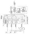
- Fig. 8 is a block diagram showing an input stage of an ATM switching device employing a header conversion method according to a third embodiment of the present invention;
- Fig. 9 is a block diagram showing the input stage of the ATM switching device of Fig. 8 for explanation of an operation of the third embodiment; and
- Fig. 10 is a schematic diagram showing a header conversion method according to the third embodiment.
-
- Referring to Fig. 2, an ATM switching device employing a header conversion circuit according to a first embodiment of the present invention is provided with a
line interface section 1 accommodating N incoming lines. - The
line interface section 1 includes N (N is an integer greater than 1) line interfaces 11.1 to 11.N, each of which is connected to a corresponding incoming line to receive data from another ATM switching device or a subscriber communication device. Further the respective line interfaces 11.1 to 11.N have line numbers (here, #0 to #N-1) uniquely assigned thereto. A cell output of each of the line interfaces 11.1 to 11.N is connected to amultiplexer 2 and a sequence of cells multiplexed by themultiplexer 2 is output to aheader conversion section 3. Theheader conversion section 3 includes aheader converter 31, aline number converter 32, and a header conversion table 33. - The
header converter 31 outputs the line number and the routing information VPI/VCI for each cell to theline number converter 32 and the header conversion table 33, respectively. Theheader converter 31 receives necessary information corresponding to the line number and the routing information from the header conversion table 33 and converts the header of each cell using the necessary information. The cell with converted header information is transferred to the switch fabric (not shown), in which the cell is forwarded to an appropriate output port of the switch fabric depending on the converted header Information. - As shown in Fig. 3, the
multiplexer 2 multiplexes incoming fixed-length packets (cells) received from the respective line interfaces 11.1 to 11.N according to a multiplexing control signal to produce a sequence of cells. The sequence of cells is output to theheader converter 31 with each cell having the line number of a corresponding line interface at which the cell arrived. - When receiving the sequence of cells from the
multiplexer 2, theheader converter 31 reads the line number and routing information VPI/VCI for each cell and outputs the line number to theline number converter 32 and the routing information VPI/VCI to the header conversion table 33. A converted line number by theline number converter 32 is output to the header conversion table 33. - In the case of a redundant system, the
line number converter 32 allows the line number to be converted to selected line number depending on a control signal. Since the system as shown in Fig. 2 has no redundant architecture, theline number converter 32 does not substantially convert the line number. - Referring to Fig. 4, the line number and the routing information VPI/VCI for each cell are used as a key to search the header conversion table 33. For example, when receiving a cell arriving at the line interface 11.1 having
line number # 0 assigned thereto, since the line number is not converted by theline number converter 32, theline number # 0 and the routing information VPI/VCI of the cell are used as a key to search the header conversion table 33. When a match is found, the corresponding output information composed of an outgoing line number, outgoing routing information VPI/VCI, and control information is returned to theheader converter 31. Using the output information returned from the header conversion table 33, theheader converter 31 converts the header of the cell and outputs the cell with converted header to the switch fabric. - In general, the header conversion table 33 includes a decoder or CAM (Contents Addressable Memory) and a random access memory (RAM) storing output information. After the line number and the routing information VPI/VCI are converted to a memory address by the decoder or CAM, the output information stored in the RAM is accessed according to the memory address and is returned to the
header converter 31. - Referring to Fig. 5, an ATM switching device employing a header conversion circuit according to a second embodiment of the present invention has a 1+1 redundant architecture, in which circuit blocks similar to those previously described with reference to Fig. 2 are denoted by the same reference numerals.
- A
line interface section 4 accommodates aworking line 401 and areserved line 402, which are connected to a line interface 41.1 and a line interface 41.2, respectively. Here,line numbers # 0 and #1 are assigned to the line interface 41.1 and the line interface 41.2, respectively. Plural line interface sections having the same circuit as theline interface section 4 may be connected to themultiplexer 2. - When normally operating. the same data is transferred on both the
working line 401 and thereserved line 402. However, themultiplexer 2 multiplexes cells received from only working line interfaces to produce a sequence of cells according to a multiplex control signal- In such a normal condition, the operation of theheader conversion section 3 is the same as that in the first embodiment as shown in Fig. 4. - As shown in Fig. 6, in the event of a failure on the
working line 401 or the line interface 41.1, the occurrence of the failure is detected by a well-known means and thereby the multiplex control signal is changed so as to control themultiplexer 2 such that cells received from the line interface 41.2 connected to thereserved line 402 are selected to be multiplexed. At the same time, the conversion control signal causes theline number converter 32 to switch theline numbex # 1 to theline number # 0. - Referring to Fig. 7, more specifically, when the
multiplexer 2 switches an incoming route from the line interface 41.1 to the line interface 41.2 in response to the occurrence of the failure. cells output from the line interface 41.2 having theline number # 1 assigned thereto are multiplexed and transferred to theheader converter 31 together with theline number # 1. - The
header converter 31 reads theline number # 1 and the routing information from each of the cells and outputs them to theline number converter 32 and the header conversion table 33. Since theline number converter 32 has been set to such a state that the workingline number # 1 is converted to the reservedline number # 0, the output information corresponding to input information for theline number # 0 is accessed and returned to theheader converter 31. In other words, theheader converter 31 can obtain the same output information as in the normal case from the header conversion table 33 after and before the failure on the workingline 401 occurs. Accordingly, the cells on the reserved system can be transferred to the switch fabric as the case of the cells on the working system without the need of the installation of information for the reserved system in the header conversion table 33. - Referring to Fig. 8, an ATM switching device employing a header conversion circuit according to a third embodiment of the present invention has an N:1 redundant architecture, in which circuit blocks similar to those previously described with reference to Fig. 2 are denoted by the same reference numerals.
- A
line interface section 5 includes a workingline interface section 5a composed of N working line interfaces 51.1 to 51.N corresponding to respective ones ofN working lines 401. 402, 403, ... and a reserved line interface 51.(N+1). Here,line numbers # 0 to #N are assigned to the working line interfaces 51.1 to 51.N and thereserved line interface 51. (N+1), respectively. - In addition, a
selector switch 6 is connected between the N working lines and the reserved line interface 51.(N+1). Theselector switch 6 has N input ports connected to respective ones of the N working lines and one output port connected to the reserved line interface 51.(N+1). When one of the working line interfaces 51.1 to 51.N is faulty, theselector switch 6 is switched by a selection signal so that the reserved line interface 51.(N+1) is used in place of the fault line interface. The working and reserved line interfaces 51.1 to 51.(N+1) are connected to themultiplexer 2. - When normally operating. the
multiplexer 2 multiplexes cells received from only working line interfaces 51.1 to 51.N to produce a sequence of cells according to a multiplex control signal. In such a normal condition, the operation of theheader conversion section 3 is the same as that in the first embodiment as shown in Fig. 4. - As shown in Fig. 9, in the event of a failure on the working line interface 51.1, the occurrence of the failure is detected by a well-known means because no cell is received from the working line interface 51.1. When the occurrence of the failure is detected on the working line interface 51.1, the selection signal is changed so as to connect the working
line 401 corresponding to the fault line interface 51.1 to the reserved line interface 51.(N+1) and thereby incoming cells on the workingline 401 are transferred to the reserved line interface 51.(N+1). Further the multiplex control signal is changed so as to control themultiplexer 2 such that cells received from the reservedline interface 51. (N+1) are selected to be multiplexed. At the same time, the conversion control signal causes theline number converter 32 to convert the line number #N to theline number # 0. - Referring to Fig. 10, more specifically. when the
multiplexer 2 switches an incoming route from the line interface 51.1 to thereserved line interface 51. (N+1) in response to the occurrence of the failure, cells output from the reserved line interface 51.(N+1) having the line number #N assigned thereto are multiplexed and transferred to theheader converter 31 together with the line number #N. - The
header converter 31 reads the line number #N and the routing information from each of the cells and outputs them to theline number converter 32 and the header conversion table 33. Since theline number converter 32 has been set to such a state that the line number #N is converted to theline number # 0, the output information corresponding to input information for theline number # 0 is accessed and returned to theheader converter 31. In other words, theheader converter 31 can obtain the same output information as in the normal case from the header conversion table 33 after and before the failure on the working line interface 51.1 occurs. Accordingly, the cells coming in on the workingline 401 can be transferred to the switch fabric through the reserved line interface 51.(N+1) as the case of the cells on the working line interface 51.1 without the need of the installation of information for the reserved line interface 51.(N+1) in the header conversion table 33. - In the above embodiments, the
line number converter 32 is provided in theheader conversion section 3. Alternatively, it is possible to provide theline number converter 32 in the reserved line interface 41.2 or 51.(N+1) or themultiplexer 2. Further, it is possible to provide theline number converter 32 on the cell transfer line between themultiplexer 2 and theheader conversion section 3. - As described above, there is no need of a conversion table used for a reserved line interface, resulting in the reduced size of a decoder or CAM for converting the routing information to a memory address and further the reduced amount of memory required for the header conversion table. This may promote miniaturization and achieve cost-reduction effectively.
- Since the same table as the working header conversion table is accessed even if switching to the reserved line interface, the identical information can be obtained to convert the header information in both working and reserved systems. Accordingly, it can be avoided that the line switching cannot be successfully performed. Further, in the case of N:1 redundant system, there is no need of the installation of data duplicating means. Since data duplication is not needed, high-speed line switching can be achieved.
Claims (17)
- A device for converting a header of a packet to forward the packet to an appropriate one of output ports of a switch fabric, comprising:
redundant incoming line systems (41.1, 41.2, 51.1-51.N, 51. (N+1));
characterized by:a header conversion table (33) storing a set of header conversion information for one of the redundant incoming line systems; anda header Converter (31. .32) for converting a header of a packet received from each of the redundant incoming line sysrems by referring the set of header conversion information. - A device for converting a header of a packet to forward the packet to an appropriate one of output ports of a switch fabric, comprising:characterized by:at least one line interface (41.1);a reserved line interface (41.2) corresponding to each of said at least one line interface;a selector (2) for normally selecting a corresponding line interface to receive a packet stream and, when a failure occurs on a system corresponding to the corresponding line interface, selecting the reserved line interface to receive the packet stream;a header conversion table (33) storing header conversion information for each of said at least one line interface; anda header converter (31, 32) for converting the header of a packet received from the reserved line interface selected by the selector by referring to the header conversion information for the corresponding line interface.
- The device according to claim 2, wherein said at least one line interface and the reserved line interface have line numbers uniquely assigned thereto, wherein a line number of each of said at least one line interface and the reserved line interface is transferred to the header converter.
wherein the header converter comprises:a line number converter (32) for converting a line number of the reserved line Interface to a line number of the corresponding line interface; anda controller (31) for accessing the header conversion information for the corresponding line interface by using the line number of the corresponding line interface. - The device according to claim 3, wherein, when the reserved line interface is selected by the selector due to occurrence of the failure, the line number converter converts the line number of the reserved line interface to the line number of the corresponding line interface.
- The device according to claim 2, wherein the selector is a multiplexer for multiplexing selected outputs of said at least one line interface and the reserved line interface to produce a sequence of packets, which is transferred to the header converter.
- The device according to claim 5, wherein the multiplexer transfers a line number of each of said at least one line interface and the reserved line interface to the header converter.
- A device for converting a header of a packet to forward the packet to an appropriate one of output ports of a switch fabric, comprising:characterized by:a plurality of line interfaces (51.1-51.N) connected to respective ones of incoming lines ;a reserved line interface (51.(N+1));a first selector (6) for connecting a selected one of the incoming lines to the reserved line interface when a failure occurs on a system corresponding to a corresponding line interface;a second selector (2) for normally selecting each of the plurality of line interfaces and, when the failure occurs on the system corresponding to the corresponding line interface. selecting the reserved line interface in place of the corresponding line interface;a header conversion table (33) storing header conversion information for each of the plurality of line interfaces; anda header converter (31. 32) for converting the header of a packet received from the reserved line interface selected by the second selector by referring to the header conversion information for the corresponding line interface.
- The device according to claim 7, wherein the plurality of line interfaces and the reserved line interface have line numbers uniquely assigned thereto, wherein a line number of each of the plurality of line interfaces and the reserved line interface is transferred to the header converter,
wherein the header converter comprises:a line number converter (32) for converting a line number of the reserved line interface to a line number of the corresponding line interface: anda controller (31) for accessing the header conversion information for the corresponding line interface by using the line number of the corresponding line interface. - The device according to claim 8, wherein, when the reserved line interface is selected by the second selector due to occurrence of the failure, the line number converter converts the line number of the reserved line interface to the line number of the corresponding line interface.
- The device according to claim 7, wherein the second selector is a multiplexer for multiplexing selected outputs of the plurality of line interfaces and the reserved line interface to produce a sequence of packets, which is transferred to the header converter.
- The device according to claim 10, wherein the multiplexer transfers a line number of each of the plurality of line interfaces and the reserved line interface to the header converter.
- The device according to claim 2, wherein the switch fabric is an ATM (asynchronous transfer mode) switching device and the packet is an ATM cell.
- The device according to claim 7, wherein the switch fabric is an ATM (asynchronous transfer mode) switching device and the packet is an ATM cell.
- A method for converting a header of a packet to forward the packet to an appropriate one of output ports of a switch fabric in an ATM (asynchronous transfer mode) switching device having redundant incoming line systems, characterized by the steps of:storing a set of neader conversion information for one of the redundant incoming line systems; andconverting a header of a packet received from each of the redundant incoming line systems by referring the set of header conversion information.
- A method for converting a header of a packet to forward the packet to an appropriate one of output ports of a switch fabric in an ATM (asynchronous transfer mode) switching device having at least one line interface and a reserved line interface corresponding to each of said at least one line interface, comprising the steps of:a) normally selecting a corresponding line interface to receive a packet stream;b) when a failure occurs on a system corresponding to the corresponding line interface, selecting the reserved line interface to receive the packet stream;
characterized by the steps of:c) storing header conversion information for each of said at least one line interface; andd) converting the header of a packet received from the reserved line interface by referring to the header conversion information for the corresponding line interface. - The method according to claim 15, wherein said at least one line interface and the reserved line interface have line numbers uniquely assigned thereto, wherein the step (d) comprises the steps of:receiving a line number of each of said at least one line interface and the reserved line interface;converting a line number of the reserved line interface to a line number of the corresponding line interface; andaccessing the header conversion information for the corresponding line interface by using the line number of the corresponding line interface.
- A method for converting a header of a packet to forward the packet to an appropriate one of output ports of a switch fabric in an ATM (asynchronous transfer mode) switching device having a plurality of line interfaces connected to respective ones of incoming lines and a reserved line interface, comprising the steps of:characterized by the steps of:connecting a selected one of the incoming lines to the reserved line interface when a failure occurs on a system corresponding to a corresponding line interface;normally selecting each of the plurality of line interfaces ;when the failure occurs on the system corresponding to the corresponding line interface, selecting the reserved line interface in place of the corresponding line interface;storing header conversion information for each of the plurality of line interfaces; andconverting the header of a packet received from the reserved line interface by referring to the header conversion information for the corresponding line interface.
Applications Claiming Priority (2)
| Application Number | Priority Date | Filing Date | Title |
|---|---|---|---|
| JP2000110352A JP3589149B2 (en) | 2000-04-12 | 2000-04-12 | Line switching header conversion circuit for ATM exchange and header conversion method used therefor |
| JP2000110352 | 2000-04-12 |
Publications (2)
| Publication Number | Publication Date |
|---|---|
| EP1146698A1 true EP1146698A1 (en) | 2001-10-17 |
| EP1146698B1 EP1146698B1 (en) | 2007-06-13 |
Family
ID=18622876
Family Applications (1)
| Application Number | Title | Priority Date | Filing Date |
|---|---|---|---|
| EP20010109152 Expired - Lifetime EP1146698B1 (en) | 2000-04-12 | 2001-04-12 | Header conversion technique in ATM switch |
Country Status (5)
| Country | Link |
|---|---|
| US (3) | US7058013B2 (en) |
| EP (1) | EP1146698B1 (en) |
| JP (1) | JP3589149B2 (en) |
| CA (1) | CA2344060C (en) |
| DE (1) | DE60128854T2 (en) |
Cited By (1)
| Publication number | Priority date | Publication date | Assignee | Title |
|---|---|---|---|---|
| GB2458546A (en) * | 2008-03-28 | 2009-09-30 | Fujitsu Ltd | Network switch wherein egress port specified by ingress interface is overwritten with standby port before switch fabric for failed ports |
Families Citing this family (9)
| Publication number | Priority date | Publication date | Assignee | Title |
|---|---|---|---|---|
| JP3589149B2 (en) * | 2000-04-12 | 2004-11-17 | 日本電気株式会社 | Line switching header conversion circuit for ATM exchange and header conversion method used therefor |
| WO2002091688A1 (en) * | 2001-05-07 | 2002-11-14 | Vitesse Semiconductor Corporation | A data switching system |
| US8880709B2 (en) | 2001-09-12 | 2014-11-04 | Ericsson Television Inc. | Method and system for scheduled streaming of best effort data |
| JP2003124979A (en) * | 2001-10-10 | 2003-04-25 | Nec Corp | Selector in switchboard, circuit redundancy method, and its system |
| US7382724B1 (en) * | 2001-11-21 | 2008-06-03 | Juniper Networks, Inc. | Automatic switchover mechanism in a network device |
| US7061942B2 (en) * | 2002-05-31 | 2006-06-13 | Skystream Networks Inc. | Apparatus for redundant multiplexing and remultiplexing of program streams and best effort data |
| KR100489685B1 (en) * | 2003-02-20 | 2005-05-17 | 삼성전자주식회사 | Apparatus for transmitting packet between packet controller and network processor and method thereof |
| US8228929B2 (en) * | 2008-10-24 | 2012-07-24 | Juniper Networks, Inc. | Flow consistent dynamic load balancing |
| KR102516027B1 (en) | 2016-07-20 | 2023-03-31 | 삼성전자주식회사 | Header processing device, processor and electronic device |
Citations (3)
| Publication number | Priority date | Publication date | Assignee | Title |
|---|---|---|---|---|
| US5414701A (en) * | 1994-07-22 | 1995-05-09 | Motorola, Inc. | Method and data structure for performing address compression in an asynchronous transfer mode (ATM) system |
| US5600630A (en) * | 1993-08-31 | 1997-02-04 | Hitachi, Ltd. | Path changing system and method for use in ATM communication apparatus |
| DE19837216A1 (en) * | 1998-08-17 | 2000-02-24 | Siemens Ag | Error recovery method in active peripheral assembly group of communications system exchange |
Family Cites Families (32)
| Publication number | Priority date | Publication date | Assignee | Title |
|---|---|---|---|---|
| US4216465A (en) * | 1978-03-07 | 1980-08-05 | Hughes Aircraft Company | Programmable analog to digital converter |
| JP2960437B2 (en) * | 1989-07-14 | 1999-10-06 | 株式会社日立製作所 | Packet concentrator, network using the same, and packet switching system |
| US5166926A (en) * | 1990-12-18 | 1992-11-24 | Bell Communications Research, Inc. | Packet address look-ahead technique for use in implementing a high speed packet switch |
| US5130984A (en) * | 1990-12-18 | 1992-07-14 | Bell Communications Research, Inc. | Large fault tolerant packet switch particularly suited for asynchronous transfer mode (ATM) communication |
| JP3329604B2 (en) * | 1994-03-17 | 2002-09-30 | 富士通株式会社 | switch |
| JPH07264194A (en) | 1994-03-17 | 1995-10-13 | Fujitsu Ltd | Line associated operation device for atm exchange |
| EP0700229B1 (en) * | 1994-08-22 | 2006-06-28 | Fujitsu Limited | Connectionless communications system, test method, and intra-station control system |
| JP2655493B2 (en) * | 1994-11-04 | 1997-09-17 | 日本電気株式会社 | ATM switch system |
| JP3623997B2 (en) * | 1994-12-28 | 2005-02-23 | 富士通株式会社 | Digital exchange relay system and digital exchange |
| JPH08204716A (en) | 1995-01-26 | 1996-08-09 | Canon Inc | Atm switch |
| JPH08242240A (en) | 1995-03-06 | 1996-09-17 | Hitachi Ltd | Atm exchange and method for switching path |
| JPH08288965A (en) * | 1995-04-18 | 1996-11-01 | Hitachi Ltd | Switching system |
| JPH0927815A (en) | 1995-05-08 | 1997-01-28 | Fujitsu Ltd | Header conversion system |
| JP3437341B2 (en) | 1995-08-21 | 2003-08-18 | 富士通株式会社 | ATM switching equipment |
| JPH09261229A (en) * | 1996-03-19 | 1997-10-03 | Hitachi Ltd | Atm communication equipment |
| JPH1079747A (en) | 1996-09-05 | 1998-03-24 | Hitachi Ltd | Asynchronous transfer mode communication equipment with operation and maintenance function |
| JPH10145374A (en) | 1996-11-11 | 1998-05-29 | Hitachi Ltd | System switching method for packet connection and asynchronous transferring mode communication equipment |
| JPH10150446A (en) * | 1996-11-19 | 1998-06-02 | Fujitsu Ltd | Atm exchange system |
| JP3655716B2 (en) * | 1996-12-03 | 2005-06-02 | 富士通株式会社 | switch |
| JP3132650B2 (en) | 1997-05-12 | 2001-02-05 | 日本電気株式会社 | Virtual path switching device |
| JP3168945B2 (en) | 1997-07-10 | 2001-05-21 | 日本電気株式会社 | ATM transmission line switching system |
| JPH1141242A (en) * | 1997-07-18 | 1999-02-12 | Fujitsu Ltd | Path audit control method for exchange |
| JPH11127157A (en) * | 1997-10-20 | 1999-05-11 | Fujitsu Ltd | Atm exchange |
| US6452939B1 (en) * | 1998-03-24 | 2002-09-17 | Samsung Electronics Co., Ltd. | ATM interface device with double header conversion |
| JP2982784B2 (en) * | 1998-03-31 | 1999-11-29 | 日本電気株式会社 | ATM switch management system |
| JP2000049860A (en) | 1998-07-30 | 2000-02-18 | Nec Corp | Packet switching device |
| DE19837126B4 (en) | 1998-08-17 | 2004-02-05 | Forschungszentrum Jülich GmbH | Method and device for electrical or electrochemical manipulation of samples |
| JP3866425B2 (en) * | 1998-11-12 | 2007-01-10 | 株式会社日立コミュニケーションテクノロジー | Packet switch |
| US6985435B1 (en) * | 1998-11-17 | 2006-01-10 | Siemens Aktiengesellschaft | Method for expanding the switching network of a communications system without interrupting operation |
| JP2001053753A (en) * | 1999-08-09 | 2001-02-23 | Fujitsu Ltd | Method for switching active/reserve line and atm exchange using the same |
| JP2001217844A (en) | 2000-02-03 | 2001-08-10 | Fujitsu Ltd | Redundant configuration controller for exchange |
| JP3589149B2 (en) * | 2000-04-12 | 2004-11-17 | 日本電気株式会社 | Line switching header conversion circuit for ATM exchange and header conversion method used therefor |
-
2000
- 2000-04-12 JP JP2000110352A patent/JP3589149B2/en not_active Expired - Fee Related
-
2001
- 2001-04-11 US US09/829,972 patent/US7058013B2/en not_active Expired - Fee Related
- 2001-04-12 EP EP20010109152 patent/EP1146698B1/en not_active Expired - Lifetime
- 2001-04-12 CA CA 2344060 patent/CA2344060C/en not_active Expired - Fee Related
- 2001-04-12 DE DE2001628854 patent/DE60128854T2/en not_active Expired - Lifetime
-
2005
- 2005-08-19 US US11/207,198 patent/US8154994B2/en not_active Expired - Fee Related
-
2012
- 2012-03-07 US US13/414,338 patent/US20120224473A1/en not_active Abandoned
Patent Citations (3)
| Publication number | Priority date | Publication date | Assignee | Title |
|---|---|---|---|---|
| US5600630A (en) * | 1993-08-31 | 1997-02-04 | Hitachi, Ltd. | Path changing system and method for use in ATM communication apparatus |
| US5414701A (en) * | 1994-07-22 | 1995-05-09 | Motorola, Inc. | Method and data structure for performing address compression in an asynchronous transfer mode (ATM) system |
| DE19837216A1 (en) * | 1998-08-17 | 2000-02-24 | Siemens Ag | Error recovery method in active peripheral assembly group of communications system exchange |
Cited By (2)
| Publication number | Priority date | Publication date | Assignee | Title |
|---|---|---|---|---|
| GB2458546A (en) * | 2008-03-28 | 2009-09-30 | Fujitsu Ltd | Network switch wherein egress port specified by ingress interface is overwritten with standby port before switch fabric for failed ports |
| US8203935B2 (en) | 2008-03-28 | 2012-06-19 | Fujitsu Limited | Signal transmitting device for switching forwarding destination |
Also Published As
| Publication number | Publication date |
|---|---|
| US20020024928A1 (en) | 2002-02-28 |
| CA2344060A1 (en) | 2001-10-12 |
| US8154994B2 (en) | 2012-04-10 |
| US20120224473A1 (en) | 2012-09-06 |
| EP1146698B1 (en) | 2007-06-13 |
| JP3589149B2 (en) | 2004-11-17 |
| US7058013B2 (en) | 2006-06-06 |
| US20060050699A1 (en) | 2006-03-09 |
| JP2001298457A (en) | 2001-10-26 |
| CA2344060C (en) | 2006-12-05 |
| DE60128854D1 (en) | 2007-07-26 |
| DE60128854T2 (en) | 2007-10-18 |
Similar Documents
| Publication | Publication Date | Title |
|---|---|---|
| US8154994B2 (en) | Header conversion technique | |
| US5301184A (en) | Control system for switching duplicated switch units in ATM exchange | |
| US5610913A (en) | Switching equipment for performing a switching operation for a high-speed packet in broadband Integrated Services Digital Network | |
| US6327244B1 (en) | Packet handler | |
| EP0875123B1 (en) | Atm network with ring architecture | |
| KR19980064825A (en) | Distributed buffering system of A.T.M switch | |
| PL172499B1 (en) | Connection route setting up in wide-band telecommunication networks | |
| JP2629568B2 (en) | ATM cell switching system | |
| US5561661A (en) | Method for synchronizing redundantly transmitted message cell streams | |
| EP0613273A2 (en) | Packet switching system | |
| CA2062852C (en) | Two-stage, at least doubled atm reversing switching network having (2n x 2n) switching matrices | |
| US6269077B1 (en) | ATM link switching over method and apparatus | |
| US6333915B1 (en) | On-line line monitor system | |
| AU718929B2 (en) | Signal transfer device in a telecommunications network | |
| US5946294A (en) | Redundancy-optimized communication network for the transmission of communication signals | |
| JP3168945B2 (en) | ATM transmission line switching system | |
| US20010012267A1 (en) | Redundant structure control device for exchange | |
| US20020051454A1 (en) | Board duplexing apparatus for asynchronous transfer mode switch and method of controlling the same | |
| JP3614236B2 (en) | Non-instantaneous expansion system for cross-connect equipment | |
| JP3151768B2 (en) | Self-healing ring system for synchronous and asynchronous transfer modes | |
| KR100867991B1 (en) | Packet switching system for load shared switch redundancy | |
| JP3024630B2 (en) | Communication path switching device | |
| JP2747305B2 (en) | ATM switch | |
| JPH09116554A (en) | Method for transferring control information of atm exchange, and atm exchange | |
| JP3067085B2 (en) | ATM switch |
Legal Events
| Date | Code | Title | Description |
|---|---|---|---|
| PUAI | Public reference made under article 153(3) epc to a published international application that has entered the european phase |
Free format text: ORIGINAL CODE: 0009012 |
|
| AK | Designated contracting states |
Kind code of ref document: A1 Designated state(s): AT BE CH CY DE DK ES FI FR GB GR IE IT LI LU MC NL PT SE TR Kind code of ref document: A1 Designated state(s): DE GB |
|
| AX | Request for extension of the european patent |
Free format text: AL;LT;LV;MK;RO;SI |
|
| 17P | Request for examination filed |
Effective date: 20011212 |
|
| AKX | Designation fees paid |
Free format text: DE GB |
|
| RAP1 | Party data changed (applicant data changed or rights of an application transferred) |
Owner name: JUNIPER NETWORKS, INC. |
|
| GRAP | Despatch of communication of intention to grant a patent |
Free format text: ORIGINAL CODE: EPIDOSNIGR1 |
|
| GRAS | Grant fee paid |
Free format text: ORIGINAL CODE: EPIDOSNIGR3 |
|
| GRAA | (expected) grant |
Free format text: ORIGINAL CODE: 0009210 |
|
| AK | Designated contracting states |
Kind code of ref document: B1 Designated state(s): DE GB |
|
| REG | Reference to a national code |
Ref country code: GB Ref legal event code: FG4D |
|
| REF | Corresponds to: |
Ref document number: 60128854 Country of ref document: DE Date of ref document: 20070726 Kind code of ref document: P |
|
| PLBE | No opposition filed within time limit |
Free format text: ORIGINAL CODE: 0009261 |
|
| STAA | Information on the status of an ep patent application or granted ep patent |
Free format text: STATUS: NO OPPOSITION FILED WITHIN TIME LIMIT |
|
| 26N | No opposition filed |
Effective date: 20080314 |
|
| PGFP | Annual fee paid to national office [announced via postgrant information from national office to epo] |
Ref country code: GB Payment date: 20130429 Year of fee payment: 13 Ref country code: DE Payment date: 20130429 Year of fee payment: 13 |
|
| REG | Reference to a national code |
Ref country code: DE Ref legal event code: R119 Ref document number: 60128854 Country of ref document: DE |
|
| REG | Reference to a national code |
Ref country code: DE Ref legal event code: R079 Ref document number: 60128854 Country of ref document: DE Free format text: PREVIOUS MAIN CLASS: H04L0012560000 Ipc: H04L0012935000 |
|
| GBPC | Gb: european patent ceased through non-payment of renewal fee |
Effective date: 20140412 |
|
| REG | Reference to a national code |
Ref country code: DE Ref legal event code: R119 Ref document number: 60128854 Country of ref document: DE Effective date: 20141101 Ref country code: DE Ref legal event code: R079 Ref document number: 60128854 Country of ref document: DE Free format text: PREVIOUS MAIN CLASS: H04L0012560000 Ipc: H04L0012935000 Effective date: 20141218 |
|
| PG25 | Lapsed in a contracting state [announced via postgrant information from national office to epo] |
Ref country code: DE Free format text: LAPSE BECAUSE OF NON-PAYMENT OF DUE FEES Effective date: 20141101 Ref country code: GB Free format text: LAPSE BECAUSE OF NON-PAYMENT OF DUE FEES Effective date: 20140412 |