EP1146730A2 - Method and apparatus for reproducing compressively coded data - Google Patents
Method and apparatus for reproducing compressively coded data Download PDFInfo
- Publication number
- EP1146730A2 EP1146730A2 EP01107979A EP01107979A EP1146730A2 EP 1146730 A2 EP1146730 A2 EP 1146730A2 EP 01107979 A EP01107979 A EP 01107979A EP 01107979 A EP01107979 A EP 01107979A EP 1146730 A2 EP1146730 A2 EP 1146730A2
- Authority
- EP
- European Patent Office
- Prior art keywords
- data
- audio
- frame
- video
- reproduction
- Prior art date
- Legal status (The legal status is an assumption and is not a legal conclusion. Google has not performed a legal analysis and makes no representation as to the accuracy of the status listed.)
- Withdrawn
Links
Images


Classifications
-
- G—PHYSICS
- G11—INFORMATION STORAGE
- G11B—INFORMATION STORAGE BASED ON RELATIVE MOVEMENT BETWEEN RECORD CARRIER AND TRANSDUCER
- G11B27/00—Editing; Indexing; Addressing; Timing or synchronising; Monitoring; Measuring tape travel
- G11B27/10—Indexing; Addressing; Timing or synchronising; Measuring tape travel
- G11B27/102—Programmed access in sequence to addressed parts of tracks of operating record carriers
- G11B27/105—Programmed access in sequence to addressed parts of tracks of operating record carriers of operating discs
-
- G—PHYSICS
- G11—INFORMATION STORAGE
- G11B—INFORMATION STORAGE BASED ON RELATIVE MOVEMENT BETWEEN RECORD CARRIER AND TRANSDUCER
- G11B27/00—Editing; Indexing; Addressing; Timing or synchronising; Monitoring; Measuring tape travel
- G11B27/10—Indexing; Addressing; Timing or synchronising; Measuring tape travel
- G11B27/19—Indexing; Addressing; Timing or synchronising; Measuring tape travel by using information detectable on the record carrier
- G11B27/28—Indexing; Addressing; Timing or synchronising; Measuring tape travel by using information detectable on the record carrier by using information signals recorded by the same method as the main recording
- G11B27/30—Indexing; Addressing; Timing or synchronising; Measuring tape travel by using information detectable on the record carrier by using information signals recorded by the same method as the main recording on the same track as the main recording
- G11B27/3027—Indexing; Addressing; Timing or synchronising; Measuring tape travel by using information detectable on the record carrier by using information signals recorded by the same method as the main recording on the same track as the main recording used signal is digitally coded
-
- H—ELECTRICITY
- H04—ELECTRIC COMMUNICATION TECHNIQUE
- H04N—PICTORIAL COMMUNICATION, e.g. TELEVISION
- H04N21/00—Selective content distribution, e.g. interactive television or video on demand [VOD]
- H04N21/20—Servers specifically adapted for the distribution of content, e.g. VOD servers; Operations thereof
- H04N21/23—Processing of content or additional data; Elementary server operations; Server middleware
- H04N21/236—Assembling of a multiplex stream, e.g. transport stream, by combining a video stream with other content or additional data, e.g. inserting a URL [Uniform Resource Locator] into a video stream, multiplexing software data into a video stream; Remultiplexing of multiplex streams; Insertion of stuffing bits into the multiplex stream, e.g. to obtain a constant bit-rate; Assembling of a packetised elementary stream
- H04N21/2368—Multiplexing of audio and video streams
-
- H—ELECTRICITY
- H04—ELECTRIC COMMUNICATION TECHNIQUE
- H04N—PICTORIAL COMMUNICATION, e.g. TELEVISION
- H04N21/00—Selective content distribution, e.g. interactive television or video on demand [VOD]
- H04N21/40—Client devices specifically adapted for the reception of or interaction with content, e.g. set-top-box [STB]; Operations thereof
- H04N21/43—Processing of content or additional data, e.g. demultiplexing additional data from a digital video stream; Elementary client operations, e.g. monitoring of home network or synchronising decoder's clock; Client middleware
- H04N21/4302—Content synchronisation processes, e.g. decoder synchronisation
- H04N21/4305—Synchronising client clock from received content stream, e.g. locking decoder clock with encoder clock, extraction of the PCR packets
-
- H—ELECTRICITY
- H04—ELECTRIC COMMUNICATION TECHNIQUE
- H04N—PICTORIAL COMMUNICATION, e.g. TELEVISION
- H04N21/00—Selective content distribution, e.g. interactive television or video on demand [VOD]
- H04N21/40—Client devices specifically adapted for the reception of or interaction with content, e.g. set-top-box [STB]; Operations thereof
- H04N21/43—Processing of content or additional data, e.g. demultiplexing additional data from a digital video stream; Elementary client operations, e.g. monitoring of home network or synchronising decoder's clock; Client middleware
- H04N21/4302—Content synchronisation processes, e.g. decoder synchronisation
- H04N21/4307—Synchronising the rendering of multiple content streams or additional data on devices, e.g. synchronisation of audio on a mobile phone with the video output on the TV screen
- H04N21/43072—Synchronising the rendering of multiple content streams or additional data on devices, e.g. synchronisation of audio on a mobile phone with the video output on the TV screen of multiple content streams on the same device
-
- H—ELECTRICITY
- H04—ELECTRIC COMMUNICATION TECHNIQUE
- H04N—PICTORIAL COMMUNICATION, e.g. TELEVISION
- H04N21/00—Selective content distribution, e.g. interactive television or video on demand [VOD]
- H04N21/40—Client devices specifically adapted for the reception of or interaction with content, e.g. set-top-box [STB]; Operations thereof
- H04N21/43—Processing of content or additional data, e.g. demultiplexing additional data from a digital video stream; Elementary client operations, e.g. monitoring of home network or synchronising decoder's clock; Client middleware
- H04N21/432—Content retrieval operation from a local storage medium, e.g. hard-disk
- H04N21/4325—Content retrieval operation from a local storage medium, e.g. hard-disk by playing back content from the storage medium
-
- H—ELECTRICITY
- H04—ELECTRIC COMMUNICATION TECHNIQUE
- H04N—PICTORIAL COMMUNICATION, e.g. TELEVISION
- H04N21/00—Selective content distribution, e.g. interactive television or video on demand [VOD]
- H04N21/40—Client devices specifically adapted for the reception of or interaction with content, e.g. set-top-box [STB]; Operations thereof
- H04N21/43—Processing of content or additional data, e.g. demultiplexing additional data from a digital video stream; Elementary client operations, e.g. monitoring of home network or synchronising decoder's clock; Client middleware
- H04N21/434—Disassembling of a multiplex stream, e.g. demultiplexing audio and video streams, extraction of additional data from a video stream; Remultiplexing of multiplex streams; Extraction or processing of SI; Disassembling of packetised elementary stream
- H04N21/4341—Demultiplexing of audio and video streams
-
- H—ELECTRICITY
- H04—ELECTRIC COMMUNICATION TECHNIQUE
- H04N—PICTORIAL COMMUNICATION, e.g. TELEVISION
- H04N5/00—Details of television systems
- H04N5/04—Synchronising
-
- H—ELECTRICITY
- H04—ELECTRIC COMMUNICATION TECHNIQUE
- H04N—PICTORIAL COMMUNICATION, e.g. TELEVISION
- H04N9/00—Details of colour television systems
- H04N9/79—Processing of colour television signals in connection with recording
- H04N9/80—Transformation of the television signal for recording, e.g. modulation, frequency changing; Inverse transformation for playback
- H04N9/804—Transformation of the television signal for recording, e.g. modulation, frequency changing; Inverse transformation for playback involving pulse code modulation of the colour picture signal components
- H04N9/8042—Transformation of the television signal for recording, e.g. modulation, frequency changing; Inverse transformation for playback involving pulse code modulation of the colour picture signal components involving data reduction
-
- G—PHYSICS
- G11—INFORMATION STORAGE
- G11B—INFORMATION STORAGE BASED ON RELATIVE MOVEMENT BETWEEN RECORD CARRIER AND TRANSDUCER
- G11B2220/00—Record carriers by type
- G11B2220/20—Disc-shaped record carriers
- G11B2220/25—Disc-shaped record carriers characterised in that the disc is based on a specific recording technology
- G11B2220/2537—Optical discs
- G11B2220/2562—DVDs [digital versatile discs]; Digital video discs; MMCDs; HDCDs
-
- H—ELECTRICITY
- H04—ELECTRIC COMMUNICATION TECHNIQUE
- H04N—PICTORIAL COMMUNICATION, e.g. TELEVISION
- H04N21/00—Selective content distribution, e.g. interactive television or video on demand [VOD]
- H04N21/40—Client devices specifically adapted for the reception of or interaction with content, e.g. set-top-box [STB]; Operations thereof
- H04N21/41—Structure of client; Structure of client peripherals
- H04N21/426—Internal components of the client ; Characteristics thereof
-
- H—ELECTRICITY
- H04—ELECTRIC COMMUNICATION TECHNIQUE
- H04N—PICTORIAL COMMUNICATION, e.g. TELEVISION
- H04N5/00—Details of television systems
- H04N5/44—Receiver circuitry for the reception of television signals according to analogue transmission standards
- H04N5/60—Receiver circuitry for the reception of television signals according to analogue transmission standards for the sound signals
-
- H—ELECTRICITY
- H04—ELECTRIC COMMUNICATION TECHNIQUE
- H04N—PICTORIAL COMMUNICATION, e.g. TELEVISION
- H04N9/00—Details of colour television systems
- H04N9/79—Processing of colour television signals in connection with recording
- H04N9/80—Transformation of the television signal for recording, e.g. modulation, frequency changing; Inverse transformation for playback
- H04N9/804—Transformation of the television signal for recording, e.g. modulation, frequency changing; Inverse transformation for playback involving pulse code modulation of the colour picture signal components
- H04N9/806—Transformation of the television signal for recording, e.g. modulation, frequency changing; Inverse transformation for playback involving pulse code modulation of the colour picture signal components with processing of the sound signal
- H04N9/8063—Transformation of the television signal for recording, e.g. modulation, frequency changing; Inverse transformation for playback involving pulse code modulation of the colour picture signal components with processing of the sound signal using time division multiplex of the PCM audio and PCM video signals
-
- H—ELECTRICITY
- H04—ELECTRIC COMMUNICATION TECHNIQUE
- H04N—PICTORIAL COMMUNICATION, e.g. TELEVISION
- H04N9/00—Details of colour television systems
- H04N9/79—Processing of colour television signals in connection with recording
- H04N9/80—Transformation of the television signal for recording, e.g. modulation, frequency changing; Inverse transformation for playback
- H04N9/82—Transformation of the television signal for recording, e.g. modulation, frequency changing; Inverse transformation for playback the individual colour picture signal components being recorded simultaneously only
- H04N9/8205—Transformation of the television signal for recording, e.g. modulation, frequency changing; Inverse transformation for playback the individual colour picture signal components being recorded simultaneously only involving the multiplexing of an additional signal and the colour video signal
Definitions
- the present invention relates to a method and an apparatus for reproducing compressively coded data and, more particularly, to a method and an apparatus for reproducing video frames and audio frames from an arbitrary reproduction start time in a data stream in which compressively coded data are multiplexed.
- the DVD-Video Recording which is one of the DVD standards and has most recently been standardized, defines editing of a program stream by an end user using a DVD-RAM disk or the like, and provides a new tool called an entry point.
- the entry point is defined by time.
- the user can start data reproduction from an arbitrary point (time). Therefore, the entry point can be interpreted as a reproduction start time.
- a description will be given of a method for reproducing compressively coded data, when the reproduction is started from an entry point.
- a program stream 301 is composed of a series of packs 302, and each pack 302 is composed of a pack header 303, a system header 304, and at least one packet 305.
- the pack header 303 starts with a pack start code 307 (0x000001BA, where 0x indicates hexadecimal notation), and parameter data 308 of the pack, such as a reference clock value called SCR (System Clock Reference) and the like, are described just after the pack start code 307.
- SCR System Clock Reference
- the system header 304 starts with a system header start code 309 (0x000001BB), and parameter data 310 of the entire program stream, such as the bit rate, the number of audio channels, the number of video channels, and the like, are described just after the system header start code 309.
- the packet 305 starts with a packet start code 311, and parameter data 312 of the packet, such as a reproduction time called PTS (Presentation Time Stamp) and the like, are described just after the packet start code 311, and compressively coded data of video or audio, called an elementary stream 313, is described just after the parameter data 312.
- PTS Presentation Time Stamp
- the parameter data 312 is information to be used when the elementary stream 313 is decoded.
- the packet start code 311 is composed of a packet start prefix of three bytes (0x000001) and a stream ID of one byte.
- the stream ID denotes the type of the compressively coded data included in the packet. For example, 0xEx (the last x indicates an arbitrary value) denotes a video packet, and 0xDx denotes an audio packet.
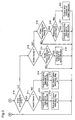
- the video elementary stream 401 has a hierarchical structure comprising six layers as follows: a sequence layer 402, a group of picture (hereinafter referred to as GOP) layer 403, a picture layer 404, a slice layer 405, a macroblock layer 406, and a block layer 407.
- a sequence layer 402 a group of picture (hereinafter referred to as GOP) layer 403
- a picture layer 404 a picture layer 404
- slice layer 405 a macroblock layer 406
- sequence header 408 One sequence starts with a sequence header 408, followed by a series of GOPs 409, and ends with a sequence end 410.
- the sequence header 408 may be placed, not only at the head of the sequence, but also in an arbitrary position between adjacent GOPs as necessary.
- the GOP 409 starts with a GOP header 411, and at least one picture 412 is described after the GOP header 411.
- the picture 412 is one piece of video frame to be displayed on the screen, and there are three kinds of pictures, I picture, P picture, and B picture.
- the I picture is short for an intra-frame coded picture that is obtained by compressive coding using only data of its own video frame.
- the P picture is short for a forward predictive coded picture that is obtained by compressive coding with reference to a video frame (I picture or P picture) in the past.
- the B picture is short for a bi-directional predictive coded picture that is obtained by compressive coding with reference to two video frames (I picture or P picture), one in the past and one in the future. It is defined that, in order to keep the independence of the GOP 409, the picture 412 just after the GOP header 411 must be an I picture.
- Each of the sequence header 408 and the GOP header 411 starts with a start code and, as described above, each start code starts with a start code prefix "0x000001" (first three bytes), followed by the type of data (last one byte).
- the start code of the sequence header 408 is called a sequence start code (Ox000001B3)
- the start code of the GOP header 411 is called a group start code (0x000001B8).
- the picture 412 starts with a picture header 413, followed by a slice layer 405, a macroblock layer 406, and a block layer 407.
- the picture header 413 starts with a picture start code 415 (0x00000100, where 0x indicates hexadecimal notation), and the picture start code 415 is followed by parameter data 416 of the picture, such as a number according to the display order of the picture, that is called a temporal reference, and the like.
- One slice is composed of a series of macroblocks starting from the upper left corner of the video frame, and one macroblock is composed of six blocks that are a fundamental processing unit.
- a VOBU 502 comprising a series of packs 503, 504, 505, ... of video, audio, and the like.
- One VOBU 502 is defined as a minimum unit that assures synchronous reproduction of video and audio within a period of 0.4 ⁇ 1.0 sec.
- the compressively coded video data in the VOBU 502 starts with a sequence header 506, and at least one GOP 507 is described after the sequence header 506. In some instances, a sequence end is described at the end of the VOBU 502.
- parameter data common through the entire program such as the video frame size, the aspect ratio, the frame rate, etc., are described.
- FIG. 7 is a block diagram illustrating the construction of a conventional apparatus for reproducing compressively coded data.
- the apparatus is provided with a transmitter 610 for transmitting a stream; a system decoder 611 for extracting a required pack from the inputted stream; a video decoder 612 for decoding video data; an audio decoder 613 for decoding audio data; and a synchronous controller 614 for controlling the operation timings of the respective constituents of the apparatus.
- a description will be given of the operation of the compressively coded data reproduction apparatus so constructed, when it starts data reproduction from an entry point.
- a VOBU 615 including an entry point is transmitted from the transmitter 610 to the system decoder 611.
- the system decoder 611 extracts a video pack and an audio pack from the inputted VOBU 615, and transmits a video elementary stream 616 and an audio elementary stream 617, which are obtained by removing packet start codes and parameter data from the video pack and the audio pack, to the video decoder 612 and the audio decoder 613, respectively. Further, the system decoder 611 transmits a PTS 618 included in the parameter data, to the synchronous controller 614.
- the video decoder 612 decodes video frames from the inputted video elementary stream 616.
- the audio decoder 613 decodes audio frames from the inputted audio elementary stream 617.
- the synchronous controller 614 controls the transmitter 610, the system decoder 611, the video decoder 612, and the audio decoder 613, thereby controlling synchronous output of a video frame 619 and an audio frame 620.
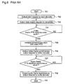
- Figure 8 is a flowchart for explaining the operation to start data reproduction according to the entry point, of the synchronous controller 614 as one of the constituents of the conventional compressively coded data reproduction apparatus.
- the operation of the synchronous controller 614 will be described in detail with reference to the flowchart of figure 8.
- the synchronous controller 614 is notified, from the outside, that an entry point value is set and data reproduction is to be started from the entry point, and outputs a start request to the transmitter 610 and the respective decoders 611, 612, and 613 (step 702).
- the transmitter 610 and the respective decoders 611, 612, and 613 start to operate.
- step 703 the synchronous controller 614 outputs a data supply request to the transmitter 610.
- the transmitter 610 performs data transmission, starting from the head of the VOBU 615 including the entry point.
- the system decoder 611 starts the above-described separation and extraction.
- step 704 the video decoder 612 performs decoding of video frames from the video elementary stream supplied from the system decoder 611, until the video frame PTS 618 supplied from the system decoder 611 matches the entry point within a predetermined threshold.
- the video decoder 612 performs only decoding, and stores the decoded video frames in a video frame buffer (not shown) in the video decoder 612. That is, the video decoder 612 does not output video data for display yet.
- the audio decoder 613 does not perform decoding until it receives an audio frame synchronous output request in step 708.
- the audio decoder 613 performs only storage of the audio elementary stream 617 supplied from the system decoder 611 in an audio bit buffer (not shown) in the audio decoder 613. In this storage process, the audio decoder 613 also controls overflow of the audio bit buffer. To be specific, when overflow is likely to occur, the audio decoder 613 discards the audio elementary stream 617 already stored in the audio bit buffer, and stores the audio elementary stream 617 that is newly transmitted in the audio bit buffer.
- step 704 when the video frame PTS 618 supplied from the system decoder 611 matches the entry point within a predetermined threshold, the synchronous controller 614 goes to step 705. In step 705, the synchronous controller 614 initializes the synchronous clock with the value of the video frame PTS 618.
- step 706 the synchronous controller 614 outputs a video frame synchronous output request to the video decoder 612.
- the video decoder 612 performs decoding of the video frame whose PTS 618 supplied from the system decoder 611 matches the entry point within the predetermined threshold and, simultaneously, outputs the video frame for display.
- output of a video frame for display is performed for the first time and, thereafter, the video decoder 612 performs decoding and output for display, on the subsequent video frames from the video elementary stream supplied from the system decoder 611, under synchronous control by the synchronous controller 614 using the synchronous clock and the video frame PTS 618 supplied from the system decoder 611.
- step 707 the synchronous controller 614 continues monitoring until the audio frame PTS 618 supplied from the system decoder 611 matches the synchronous clock within a predetermined threshold. During the monitoring, the audio decoder 613 continues only the storage of the audio elementary stream 617 in the audio bit buffer.
- the synchronous controller 614 proceeds to step 708, and outputs an audio frame synchronous output request to the audio decoder 613.
- the audio decoder 613 On receipt of this request, the audio decoder 613 performs decoding of the audio frame whose PTS 618 supplied from the system decoder 611 matches the synchronous clock within the predetermined threshold and, simultaneously, performs audio output. In this step, output of an audio frame is performed for the first time and, thereafter, the audio decoder 613 performs decoding and audio output on the subsequent audio frames from the audio elementary stream supplied from the system decoder 611, under synchronous control by the synchronous controller 614 using the synchronous clock and the audio frame PTS 618 supplied from the system decoder 611.
- step 704 when no coded video data exists in the program stream, there will not occur matching of condition that, in step 704, the video frame PTS 618 supplied from the system decoder 611 matches the entry point within the predetermined threshold, and therefore, the synchronous controller 614 cannot proceed to the following step 705 and on. In this case, even when a coded audio frame corresponding to the entry point exists in the data stream, the audio decoder 613 cannot start output of audio frames.
- the threshold should be sufficiently large.
- a video frame PTS should be assigned to each I picture, there is no such definition for other pictures. Further, there is no special definition on I pictures except that an I picture should be placed at the head of a VOBU.
- an I picture exists only at the head of a VOBU in an actual program stream, with regard to the efficiency of compressive coding, and a video frame PTS is assigned to only the I picture at the head of the VOBU.
- a threshold equivalent to one VOBU must be set, whereby the unit of synchronous control becomes, not a video frame, but a VOBU.
- the present invention is made to solve the above-described problems and has for its object to provide a method and an apparatus for reproducing compressively coded data, by which output of a video frame for display and output of an audio frame can be performed at the same timing, at precision of video frame unit and audio frame unit, when starting reproduction of compressively coded data from an entry point.
- a compressively coded data reproduction method for starting transmission of reproduced data from a video frame and an audio frame corresponding to a reproduction start time specified from the outside, on a data stream in which the following data are multiplexed: compressively coded video data comprising I pictures obtained by subjecting a series of video frames to intra-frame compressive coding, P pictures each obtained by forward-direction predictive compressive coding utilizing the correlation with a video frame in the past, and B pictures each obtained by bi-directional predictive compressive coding utilizing the correlation with two video frames in the past or in the future, or two video frames one in the past and one in the future; compressively coded audio data obtained by subjected a series of audio frames to compressive coding; and additional data relating to the compressively coded video data and the compressively coded audio data, and this method comprises the steps of: separating the compressively coded video data, the compressively coded audio data, and the additional data from the data stream and outputting these data and, at
- the compressively coded data reproduction method of the first aspect further comprises a step of judging whether a predetermined period of time has passed or not, before the step of judging whether both of the video frame and the audio frame have been decoded or not; and when the predetermined period of time has passed, an output request is made for either the video frame or the audio frame, whichever has been decoded. Therefore, even when only either of the video frame and the audio frame corresponding to the reproduction start time exists in the inputted data stream, reproduction can be normally started from the specified reproduction start time.
- the compressively coded data reproduction method of the first aspect further comprises the steps of: judging whether a predetermined period of time has passed or not, before the step of judging whether both of the video frame and the audio frame have been decoded or not; and notifying the outside that an abnormal condition occurs, when the predetermined period of time has passed and then both of the video frame and the audio frame have not yet been decoded. Therefore, even when both of the video frame and the audio frame corresponding to the reproduction start time do not exist in the inputted data stream, the reproduction start process from the specified reproduction start time can be ended without standstill.
- the data stream is a program stream defined by the MPEG standard
- the reproduction time information is a PTS (Presentation Time Stamp) defined by the MPEG standard. Therefore, it is possible to detect a video frame and an audio frame corresponding to the specified reproduction start time, decode these frames, and output the decoded video and audio frames at the same timing.
- PTS Presentation Time Stamp
- the step of performing head detection on the video frames and the audio frames includes the steps of: judging whether an effective reproduction time information is assigned to the detected head frame or not; and, in the case where no effective reproduction time information is assigned to the detected frame, when the detected frame is a video frame, calculating reproduction time information of the video frame on the basis of display output order information that is one of the additional data of the video frame, and reproduction time information and display output order information of a video frame which has been decoded prior to the video frame; on the other hand, when the detected frame is an audio frame, calculating reproduction time information of the audio frame on the basis of reproduction time information of an audio frame which has been detected prior to the audio frame. Therefore, it is possible to detect a video frame and an audio frame corresponding to the specified reproduction start time, decode these frames, and output the decoded video and audio frames at the same timing, with a precision of a video frame unit or an audio frame unit.
- the display output order information is a temporal reference defined by the MPEG standard. Therefore, it is possible to detect a video frame and an audio frame corresponding to the specified reproduction start time, decode these frames, and output the decoded video and audio frames at the same timing, with a precision of a video frame unit or an audio frame unit.
- a compressively coded data reproduction apparatus for starting transmission of reproduced data from a video frame and an audio frame corresponding to a reproduction start time specified from the outside, on a data stream in which the following data are multiplexed: compressively coded video data comprising I pictures obtained by subjecting a series of video frames to intra-frame compressive coding, P pictures each obtained by forward-direction predictive compressive coding utilizing the correlation with a video frame in the past, and B pictures each obtained by bi-directional predictive compressive coding utilizing the correlation with two video frames in the past or in the future or two video frames, one in the past and one in the future; compressively coded audio data obtained by subjected a series of audio frames to compressive coding; and additional data relating to the compressively coded video data and the compressively coded audio data, and this apparatus comprises: a system decoder for separating the compressively coded video data, the compressively coded audio data, and the additional data from the data stream and outputting these
- the synchronous controller when only either of the video frame and the audio frame has been decoded after the expiration of a predetermined period of time, the synchronous controller outputs an output request to either of the video decoder and the audio decoder, whichever has completed decoding at this point of time. Therefore, even when only either of the video frame and the audio frame corresponding to the reproduction start time exists in the inputted data stream, reproduction can be normally started from the specified reproduction start time.
- the synchronous controller when both of the video frame and the audio frame have not yet been decoded after the expiration of a predetermined period of time, the synchronous controller notifies the outside that an abnormal condition occurs. Therefore, even when both of the video frame and the audio frame corresponding to the reproduction start time do not exist in the inputted data stream, the reproduction start process from the specified reproduction start time can be ended without standstill.
- the data stream is a program stream defined by the MPEG standard
- the reproduction time information is a PTS (Presentation Time Stamp) defined by the MPEG standard. Therefore, it is possible to detect a video frame and an audio frame corresponding to the specified reproduction start time, decode these frames, and output the decoded video and audio frames at the same timing.
- PTS Presentation Time Stamp
- the synchronous controller calculates reproduction time information of the video frame on the basis of display output order information that is one of the additional data of the video frame, and reproduction time information and display output order information of a video frame which has been decoded prior to the video frame; and in the above-mentioned case, when the detected head frame is an audio frame, the synchronous controller calculates reproduction time information of the audio frame, on the basis of reproduction time information of an audio frame which has been detected prior to the audio frame. Therefore, it is possible to detect a video frame and an audio frame corresponding to the specified reproduction start time, decode these frames, and output the decoded video and audio frames at the same timing, with a precision of a video frame unit or an audio frame unit.
- the display output order information is a temporal reference defined by the MPEG standard. Therefore, it is possible to detect a video frame and an audio frame corresponding to the specified reproduction start time, decode these frames, and output the decoded video and audio frames at the same timing, with a precision of a video frame unit or an audio frame unit.
- a compressively coded data reproduction method for starting transmission of reproduced data from a picture and an audio frame corresponding to a reproduction start time specified from the outside, on a data stream in which coded video data arranged in non-chronological order, coded audio data relating to the coded video data, and additional data attendant on these data are multiplexed, and this method comprises the steps of: separating the coded video data, the coded audio data, and the additional data from the data stream and outputting these data and, at this time, performing head detection on reproduced pictures and reproduced audio data; judging whether the detected head picture per screen or head audio data is a picture per screen or audio data corresponding to the reproduction start time specified from the outside, on the basis of reproduction time information that is one of the additional data assigned to the detected picture or audio data; making a decoding request for decoding the picture per screen and the audio data corresponding to the reproduction start time; judging whether both of the picture per screen and the audio data have been decoded or not
- a compressively coded data reproduction apparatus for starting transmission of reproduced data from a picture and an audio frame corresponding to a reproduction start time specified from the outside, on a data stream in which coded video data arranged in non-chronological order, coded audio data relating to the coded video data, and additional data attendant on these data are multiplexed
- this apparatus comprises: a system decoder for separating the coded video data, the coded audio data, and the additional data from the data stream and outputting these data and, at this time, performing head detection on reproduced pictures and reproduced audio data; a video decoder for decoding pictures per screen from the coded video data; an audio decoder for decoding audio data from the coded audio data; and a synchronous controller for judging whether the detected head picture per screen or head audio data is a picture per screen or audio data corresponding to the reproduction start time specified from the outside, on the basis of reproduction time information that is one of the additional data assigned to the picture per screen or
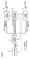
- FIG. 1 is a block diagram illustrating the construction of a compressively coded data reproduction apparatus according to a first embodiment of the present invention.
- the compressively coded data reproduction apparatus is identical to the conventional apparatus shown in figure 7 in that it is provided with a transmitter 10 for transmitting a stream; a system decoder 11 for extracting a required pack from the inputted stream; a video decoder 12 for decoding video data; an audio decoder 13 for decoding audio data; and a synchronous controller 14 for controlling the operation timings of the respective constituents of the apparatus.
- the apparatus of the first embodiment is characterized by that the system decoder 11 supplies a temporal reference defined by the MPEG standard, as display output order information, to the synchronous controller 14.
- a VOBU 15 including an entry point is transmitted from the transmitter 10 to the system decoder 11.
- the system decoder 11 extracts a video pack and an audio pack from the inputted VOBU 15, and transmits a video elementary stream 16 and an audio elementary stream 17, which are obtained by removing packet start codes and parameter data from the video pack and the audio pack, to the video decoder 12 and the audio decoder 13, respectively, and transmits a PTS 18 and a temporal reference 19, which are included in the parameter data, to the synchronous controller 14.
- system decoder 11 performs detection of head frames of compressively coded video frames and audio frames when transmitting the video elementary stream 16 and the audio elementary stream 17 which are obtained by removing the packet start codes and the parameter data from the video pack and the audio pack extracted from the inputted VOBU 15, to the video decoder 12 and the audio decoder 13, respectively.
- system decoder 11 detects the head frames, it notifies the synchronous controller 14 of the result of the detection.
- the video decoder 12 decodes video frames from the inputted video elementary stream 16.
- the audio decoder 13 decodes audio frames from the inputted audio elementary stream 17.
- the synchronous controller 14 controls the transmitter 10, the system decoder 11, the video decoder 12, and the audio decoder 13, thereby controlling synchronous output of a video frame 20 and an audio frame 21.
- FIGS 2 and 3 are flowcharts for explaining the operation of the synchronous controller 14 to start data reproduction by the entry point, according to the first embodiment.
- the operation of the synchronous controller 14 will be described in detail with reference to the flowcharts of figures 2 and 3.
- step 201 when processing is started (step 201), the synchronous controller 14 is notified, from the outside, that an entry point value and an abnormality judgement time T1 are set and data reproduction is to be started from the entry point, and clears the following flags to "0": an audio frame output preparation end flag, a video frame output preparation end flag, an audio frame detection flag, and a video frame detection flag (step 202).
- step 203 the synchronous controller 14 outputs a start request to the transmitter 10 and to the respective decoders 11, 12, and 13. On receipt of this request, the transmitter 10 and the decoders 11, 12, and 13 start to operate.
- step 204 the synchronous controller 14 outputs a data supply request to the transmitter 10.
- the transmitter 10 On receipt of this request, the transmitter 10 performs data transmission, starting from the head of the VOBU including the entry point.
- the system decoder 11 On receipt of the data from the transmitter 10, the system decoder 11 starts the above-mentioned separation and extraction.
- step 205 the synchronous controller 14 judges whether the abnormality judgement time T1 has passed or not from when the reproduction start by the entry point was notified from the outside in step 202. When the abnormality judgement time T1 has not passed yet, the synchronous controller 14 proceeds to step 206. When the abnormality judgement time T1 has already passed, the synchronous controller 14 proceeds to step 225.
- step 206 the synchronous controller 14 judges whether both of the audio frame output preparation end flag and the video frame output preparation end flag are "1" or not. When both of these flags are not “1”, the synchronous controller 14 proceeds to step 207. When both of these flags are "1”, the controller 14 proceeds to step 223.
- step 207 the synchronous controller 14 judges whether the head of the compressively coded audio frames or video frames is detected or not. When the head audio or video frame is detected, the synchronous controller 14 proceeds to step 208. When no head frame is detected, the synchronous controller 14 returns to step 205.
- step 208 the synchronous controller 14 judges whether or not an effective PTS is assigned to the compressively coded frame detected in step 207. When no effective PTS is assigned to the detected frame, the synchronous controller 14 proceeds to step 209. When an effective PTS is assigned to the detected frame, the synchronous controller 14 proceeds to step 210.
- the synchronous controller 14 calculates a PTS of the frame detected in step 207 and having no effective PTS.
- the synchronous controller 14 calculates a PTS of the detected audio frame by adding a frame unit time corresponding to one audio frame to the PTS of the audio frame which has just previously been detected.
- the synchronous controller 14 calculates a PTS (PTSn) of the detected video frame by using the following expression (1), on the basis of the PTS (PTSn-1) and the temporal reference (TRn-1) of the video frame which has just previously been detected, and the temporal reference (TRn) of the video frame detected in step 207.
- PTSn PTSn-1+(TRn-TRn-1) ⁇ [one frame unit time of video frame]
- step 210 the synchronous controller 14 judges whether or not the frame detected in step 207 is a frame corresponding to the entry point that is set from the outside in step 202.
- the synchronous controller 14 proceeds to step 211.
- the controller 14 proceeds to step 216.
- the following expression (2) is used as an conditional expression. That is, when the conditional expression holds, the synchronous controller 14 judges that the frame detected in step 207 is a frame corresponding to the entry point that is set from the outside in step 202.
- EP is the entry point value that is set from the outside in step 202
- Tfm is the frame unit time
- PTSn is the PTS of the frame detected in step 207.
- Tfm is the frame unit time corresponding to one audio frame.
- Tfm is the frame unit time corresponding to one video frame.
- step 211 the synchronous controller 14 judges whether the frame detected in step 207 is an audio frame or not. When it is an audio frame, the synchronous controller 14 proceeds to step 212. When the frame detected in step 207 is a video frame, the controller 14 proceeds to step 214.
- step 212 the synchronous controller 14 outputs a decoding request for the audio frame detected in step 207 to the audio decoder 13, and proceeds to step 213.
- the audio decoder 13 decodes the audio frame detected in step 207, and sets the audio frame output preparation end flag at "1" after the decoding is completed.
- step 213 the synchronous controller 14 sets the audio frame detection flag at "1", and returns to step 205.
- step 214 the synchronous controller 14 outputs a decoding request for the video frame detected in step 207 to the video decoder 12, and proceeds to step 215.
- the video decoder 12 decodes the video frame detected in step 207, and sets the video frame output preparation end flag at "1" after the decoding is completed.
- step 215 the synchronous controller 14 sets the video frame detection flag at "1", and returns to step 205.
- step 216 the synchronous controller 14 judges whether the frame detected on step 207 is an audio frame or not. When it is an audio frame, the synchronous controller 14 proceeds to step 217. When the frame detected in step 207 is a video frame, the controller 14 proceeds to step 219.
- step 217 the synchronous controller 14 judges whether the audio frame detection flag is "0" or not. When the audio frame detection flag is "0”, the controller 14 proceeds to step 218. When the audio frame detection flag is not "0”, the controller 14 returns to step 205.
- step 218 the synchronous controller 14 outputs a request for skipping the audio frame detected in step 207 to the audio decoder 13, and returns to step 205.
- the audio decoder 13 executes skipping of the audio frame detected in step 207. The skipping is to discard the data of the audio frame without decoding it.
- step 219 the synchronous controller 14 judges whether the video frame detection flag is "0" or not. When the video frame detection flag is "0”, the controller 14 proceeds to step 220. When the video frame detection flag is not "0”, the controller 14 returns to step 205.
- step 220 the synchronous controller 14 judges whether the frame detected in step 207 is a reference video frame (i.e., I picture or P picture) or not.
- the controller 14 proceeds to step 221.
- the controller 14 proceeds to step 222.
- step 221 the synchronous controller 14 outputs a request for decoding the video frame detected in step 207 to the video decoder 12, and returns to step 205.
- the video decoder 12 decodes the video frame detected in step 207.
- step 222 the synchronous controller 14 outputs a request for skipping the video frame detected in step 207 to the video decoder 12, and returns to step 205.
- the video decoder 12 executes skipping of the video frame detected in step 207.
- the synchronous controller 14 initializes the synchronous clock with the PTS value of the video frame which has been decoded by the video decoder 12 as the result of the decoding request outputted to the video decoder 12 in step 214, or with the PTS value of the audio frame which has been decoded by the audio decoder 13 as the result of the decoding request outputted to the audio decoder 13 in step 212.
- the synchronous controller controls reproduction of the compressively coded data by using the synchronous clock so that the audio frames and video frames are synchronously output.
- step 224 the synchronous controller 14 outputs requests for outputting video frames and audio frames to the video decoder 12 and the audio decoder 13, respectively, and ends the process of starting data reproduction according to the entry point.
- the video decoder 12 performs display output (i.e., output of data to be displayed) of the video frame which has been decoded as the result of the decoding request in step 214, and the audio decoder 13 performs audio output of the audio frame which has been decoded as the result of the decoding request in step 212.
- step 225 the synchronous controller 14 judges whether the audio frame output preparation end flag is "1" or not. When the audio frame output preparation end flag is "1”, the controller 14 proceeds to step 226. When this flag is not "1”, the controller 14 proceeds to step 228.
- step 226 the synchronous controller 14 initializes the synchronous clock with the PTS value of the audio frame which has been decoded by the audio decoder 13 as the result of decoding request outputted to the audio decoder in step 212.
- the synchronous controller 14 controls reproduction of the compressively coded data by using the synchronous clock so that the audio frames and the video frames are synchronously output.
- step 227 the synchronous controller 14 outputs an audio frame output request to the audio decoder, and ends the process of starting data reproduction according to the entry point.
- the audio decoder 13 performs audio output of the audio frame which has been decoded as the result of the decoding request outputted in step 212.
- step 228, the synchronous controller 14 judges whether the video frame output preparation end flag is "1" or not. When the video frame output preparation end flag is "1”, the controller 14 proceeds to step 229. When this flag is not "1", the controller 14 proceeds to step 231.
- step 229 the synchronous controller 14 initializes the synchronous clock with the PTS value of the video frame which has been decoded by the video decoder 12 as the result of the decoding request outputted to the video decoder in step 214.
- the synchronous controller 14 controls reproduction of the compressively coded data by using the synchronous clock so that the audio frames and the video frames are synchronously output.
- step 230 the synchronous controller 14 outputs a video frame output request to the video decoder 12 to end the process of starting data reproduction according to the entry point.
- the video decoder 12 performs display output of the video frame which has been decoded as the result of the decoding requested outputted in step 214.
- step 231 the synchronous controller 14 notifies the outside that an abnormal condition occurs.
- the compressively coded data reproduction apparatus is able to detect a video frame and an audio frame corresponding to an entry point specified from the outside within a precision of video frame unit or audio frame unit by utilizing the temporal reference 19, decode the video and audio frames, and output the video and audio frames synchronously. Further, even when only either of a video frame and an audio frame corresponding to the entry point exists in the inputted VOBU, the apparatus can start data reproduction from the entry point normally. Further, even when both of a video frame and an audio frame corresponding to the entry point are not exist in the inputted VOBU, the apparatus can end the process of starting data reproduction from the entry point, without a standstill. Accordingly, the compressively coded data reproduction apparatus of the present invention is able to detect a video frame and an audio frame corresponding to a specified reproduction start time, decode the video and audio frames, and output the decoded video and audio frames at the same timing.
- the video frame and the audio frame corresponding to the reproduction start time are output synchronously after confirming that each frame has been decoded in frame unit. Therefore, when this apparatus is applied to a stream editor that is required to have a high precision for commercial use or the like, the user can perform editing without a time lag between a picture and the corresponding audio.
- the compressively coded data are processed in frame units
- the data may be processed in screen units.
- the same effects as mentioned above are achieved.
Abstract
Description
- The present invention relates to a method and an apparatus for reproducing compressively coded data and, more particularly, to a method and an apparatus for reproducing video frames and audio frames from an arbitrary reproduction start time in a data stream in which compressively coded data are multiplexed.
- With recent developments in multimedia technology, various devices for integrally handling multiple media such as digitized video, audio, and data, typified by a DVD player and a set top box for receiving digital TV broadcast, are becoming widespread.
- Since the digitized video data or audio data have an enormous amount of codes, an efficient compressive coding technology for digital data is absolutely necessary for efficient recording and transmission. Further, in order to apply the compressive coding technology to practical devices, a multimedia data multiplexing technology for integrating the compressively coded video data, audio data, and additional information data into a single data stream is also required. Various kinds of technologies for efficient compressive coding and multimedia data multiplexing have already been put to practical use. For example, as an efficient compressive coding technology for audio data, the AC-3 method of Dolby Laboratories Licensing Corp. is widely used. On the other hand, as an efficient compressive coding technology for video data and a multimedia data multiplexing technology, the MPEG standardized by International Standards Organization (ISO) is widely used. These method and standard are also employed in the DVD standard and, especially, a program stream, that is one of multiplexing methods defined by the MPEG standard, is employed as a data stream.
- The DVD-Video Recording, which is one of the DVD standards and has most recently been standardized, defines editing of a program stream by an end user using a DVD-RAM disk or the like, and provides a new tool called an entry point. The entry point is defined by time. By defining an entry point, the user can start data reproduction from an arbitrary point (time). Therefore, the entry point can be interpreted as a reproduction start time. Hereinafter, a description will be given of a method for reproducing compressively coded data, when the reproduction is started from an entry point.
- First of all, a data structure of a program stream defined by the MPEG standard will be described with reference to figure 4.
- In figure 4, a
program stream 301 is composed of a series ofpacks 302, and eachpack 302 is composed of apack header 303, asystem header 304, and at least onepacket 305. - The
pack header 303 starts with a pack start code 307 (0x000001BA, where 0x indicates hexadecimal notation), andparameter data 308 of the pack, such as a reference clock value called SCR (System Clock Reference) and the like, are described just after thepack start code 307. - The
system header 304 starts with a system header start code 309 (0x000001BB), andparameter data 310 of the entire program stream, such as the bit rate, the number of audio channels, the number of video channels, and the like, are described just after the systemheader start code 309. - The
packet 305 starts with apacket start code 311, andparameter data 312 of the packet, such as a reproduction time called PTS (Presentation Time Stamp) and the like, are described just after thepacket start code 311, and compressively coded data of video or audio, called anelementary stream 313, is described just after theparameter data 312. Theparameter data 312 is information to be used when theelementary stream 313 is decoded. - The
packet start code 311 is composed of a packet start prefix of three bytes (0x000001) and a stream ID of one byte. The stream ID denotes the type of the compressively coded data included in the packet. For example, 0xEx (the last x indicates an arbitrary value) denotes a video packet, and 0xDx denotes an audio packet. - Next, a data structure of a video
elementary stream 401 compressively coded according to the MPEG standard, which is one of the compressively coded data described in the above-mentioned packets, will be described with reference to figure 5. - As shown in figure 5, the video
elementary stream 401 has a hierarchical structure comprising six layers as follows: asequence layer 402, a group of picture (hereinafter referred to as GOP)layer 403, apicture layer 404, aslice layer 405, amacroblock layer 406, and ablock layer 407. - One sequence starts with a
sequence header 408, followed by a series of GOPs 409, and ends with asequence end 410. Thesequence header 408 may be placed, not only at the head of the sequence, but also in an arbitrary position between adjacent GOPs as necessary. - The GOP 409 starts with a
GOP header 411, and at least onepicture 412 is described after the GOPheader 411. Thepicture 412 is one piece of video frame to be displayed on the screen, and there are three kinds of pictures, I picture, P picture, and B picture. The I picture is short for an intra-frame coded picture that is obtained by compressive coding using only data of its own video frame. The P picture is short for a forward predictive coded picture that is obtained by compressive coding with reference to a video frame (I picture or P picture) in the past. The B picture is short for a bi-directional predictive coded picture that is obtained by compressive coding with reference to two video frames (I picture or P picture), one in the past and one in the future. It is defined that, in order to keep the independence of the GOP 409, thepicture 412 just after the GOPheader 411 must be an I picture. - Each of the
sequence header 408 and the GOPheader 411 starts with a start code and, as described above, each start code starts with a start code prefix "0x000001" (first three bytes), followed by the type of data (last one byte). The start code of thesequence header 408 is called a sequence start code (Ox000001B3), and the start code of the GOPheader 411 is called a group start code (0x000001B8). - The
picture 412 starts with apicture header 413, followed by aslice layer 405, amacroblock layer 406, and ablock layer 407. Thepicture header 413 starts with a picture start code 415 (0x00000100, where 0x indicates hexadecimal notation), and thepicture start code 415 is followed byparameter data 416 of the picture, such as a number according to the display order of the picture, that is called a temporal reference, and the like. One slice is composed of a series of macroblocks starting from the upper left corner of the video frame, and one macroblock is composed of six blocks that are a fundamental processing unit. - By the way, in the DVD-Video Recording standard, as shown in figure 6(b), there is newly introduced a logical unit, that is, a VOBU 502 comprising a series of
packs sequence header 506, and at least one GOP 507 is described after thesequence header 506. In some instances, a sequence end is described at the end of theVOBU 502. In thesequence header 506, parameter data common through the entire program, such as the video frame size, the aspect ratio, the frame rate, etc., are described. - Next, a description will be given of a method for reproducing compressively coded data, starting from the entry point described above. Figure 7 is a block diagram illustrating the construction of a conventional apparatus for reproducing compressively coded data. With reference to figure 7, the apparatus is provided with a
transmitter 610 for transmitting a stream; asystem decoder 611 for extracting a required pack from the inputted stream; avideo decoder 612 for decoding video data; anaudio decoder 613 for decoding audio data; and asynchronous controller 614 for controlling the operation timings of the respective constituents of the apparatus. Hereinafter, a description will be given of the operation of the compressively coded data reproduction apparatus so constructed, when it starts data reproduction from an entry point. - As shown in figure 7, a VOBU 615 including an entry point is transmitted from the
transmitter 610 to thesystem decoder 611. Thesystem decoder 611 extracts a video pack and an audio pack from the inputted VOBU 615, and transmits a videoelementary stream 616 and an audioelementary stream 617, which are obtained by removing packet start codes and parameter data from the video pack and the audio pack, to thevideo decoder 612 and theaudio decoder 613, respectively. Further, thesystem decoder 611 transmits aPTS 618 included in the parameter data, to thesynchronous controller 614. Thevideo decoder 612 decodes video frames from the inputted videoelementary stream 616. Theaudio decoder 613 decodes audio frames from the inputted audioelementary stream 617. Thesynchronous controller 614 controls thetransmitter 610, thesystem decoder 611, thevideo decoder 612, and theaudio decoder 613, thereby controlling synchronous output of avideo frame 619 and anaudio frame 620. - Figure 8 is a flowchart for explaining the operation to start data reproduction according to the entry point, of the
synchronous controller 614 as one of the constituents of the conventional compressively coded data reproduction apparatus. Hereinafter, the operation of thesynchronous controller 614 will be described in detail with reference to the flowchart of figure 8. - Initially, when the operation is started (step 701), the
synchronous controller 614 is notified, from the outside, that an entry point value is set and data reproduction is to be started from the entry point, and outputs a start request to thetransmitter 610 and therespective decoders transmitter 610 and therespective decoders - Next, in
step 703, thesynchronous controller 614 outputs a data supply request to thetransmitter 610. On receipt of this request, thetransmitter 610 performs data transmission, starting from the head of the VOBU 615 including the entry point. On receipt of the data from thetransmitter 610, thesystem decoder 611 starts the above-described separation and extraction. - In
step 704, thevideo decoder 612 performs decoding of video frames from the video elementary stream supplied from thesystem decoder 611, until thevideo frame PTS 618 supplied from thesystem decoder 611 matches the entry point within a predetermined threshold. In this step, thevideo decoder 612 performs only decoding, and stores the decoded video frames in a video frame buffer (not shown) in thevideo decoder 612. That is, thevideo decoder 612 does not output video data for display yet. - The
audio decoder 613 does not perform decoding until it receives an audio frame synchronous output request instep 708. Theaudio decoder 613 performs only storage of the audioelementary stream 617 supplied from thesystem decoder 611 in an audio bit buffer (not shown) in theaudio decoder 613. In this storage process, theaudio decoder 613 also controls overflow of the audio bit buffer. To be specific, when overflow is likely to occur, theaudio decoder 613 discards the audioelementary stream 617 already stored in the audio bit buffer, and stores the audioelementary stream 617 that is newly transmitted in the audio bit buffer. - Next, in
step 704, when thevideo frame PTS 618 supplied from thesystem decoder 611 matches the entry point within a predetermined threshold, thesynchronous controller 614 goes to step 705. Instep 705, thesynchronous controller 614 initializes the synchronous clock with the value of thevideo frame PTS 618. - Next, in
step 706, thesynchronous controller 614 outputs a video frame synchronous output request to thevideo decoder 612. On receipt of this request, thevideo decoder 612 performs decoding of the video frame whosePTS 618 supplied from thesystem decoder 611 matches the entry point within the predetermined threshold and, simultaneously, outputs the video frame for display. In this step, output of a video frame for display is performed for the first time and, thereafter, thevideo decoder 612 performs decoding and output for display, on the subsequent video frames from the video elementary stream supplied from thesystem decoder 611, under synchronous control by thesynchronous controller 614 using the synchronous clock and thevideo frame PTS 618 supplied from thesystem decoder 611. - Next, in
step 707, thesynchronous controller 614 continues monitoring until theaudio frame PTS 618 supplied from thesystem decoder 611 matches the synchronous clock within a predetermined threshold. During the monitoring, theaudio decoder 613 continues only the storage of the audioelementary stream 617 in the audio bit buffer. - When the
audio frame PTS 618 supplied from thesystem decoder 611 matches the synchronous clock within the predetermined threshold instep 707, thesynchronous controller 614 proceeds to step 708, and outputs an audio frame synchronous output request to theaudio decoder 613. - On receipt of this request, the
audio decoder 613 performs decoding of the audio frame whosePTS 618 supplied from thesystem decoder 611 matches the synchronous clock within the predetermined threshold and, simultaneously, performs audio output. In this step, output of an audio frame is performed for the first time and, thereafter, theaudio decoder 613 performs decoding and audio output on the subsequent audio frames from the audio elementary stream supplied from thesystem decoder 611, under synchronous control by thesynchronous controller 614 using the synchronous clock and theaudio frame PTS 618 supplied from thesystem decoder 611. - In the conventional method for reproducing compressively coded data, however, since the output of audio frames is started in
step 708 after the output of video frames for display is started instep 706, it is apparent that the output of audio frames lags behind the output of video frames for display. - Further, in the above-described method, when no coded video data exists in the program stream, there will not occur matching of condition that, in
step 704, thevideo frame PTS 618 supplied from thesystem decoder 611 matches the entry point within the predetermined threshold, and therefore, thesynchronous controller 614 cannot proceed to the followingstep 705 and on. In this case, even when a coded audio frame corresponding to the entry point exists in the data stream, theaudio decoder 613 cannot start output of audio frames. - Furthermore, in the above-described method, when the
video frame PTS 618 is not assigned to each video frame in the program stream, in order to make a matching of condition that thevideo frame PTS 618 supplied from thesystem decoder 611 matches the entry point within the predetermined threshold, the threshold should be sufficiently large. To be specific, although it is defined in the DVD-Video Recording standard that a video frame PTS should be assigned to each I picture, there is no such definition for other pictures. Further, there is no special definition on I pictures except that an I picture should be placed at the head of a VOBU. However, in many instances, an I picture exists only at the head of a VOBU in an actual program stream, with regard to the efficiency of compressive coding, and a video frame PTS is assigned to only the I picture at the head of the VOBU. Taking it in consideration, a threshold equivalent to one VOBU must be set, whereby the unit of synchronous control becomes, not a video frame, but a VOBU. - The present invention is made to solve the above-described problems and has for its object to provide a method and an apparatus for reproducing compressively coded data, by which output of a video frame for display and output of an audio frame can be performed at the same timing, at precision of video frame unit and audio frame unit, when starting reproduction of compressively coded data from an entry point.
- Other objects and advantages of the invention will become apparent from the detailed description that follows. The detailed description and specific embodiments described are provided only for illustration since various additions and modifications within the scope of the invention will be apparent to those of skill in the art from the detailed description.
- According to a first aspect of the present invention, there is provided a compressively coded data reproduction method for starting transmission of reproduced data from a video frame and an audio frame corresponding to a reproduction start time specified from the outside, on a data stream in which the following data are multiplexed: compressively coded video data comprising I pictures obtained by subjecting a series of video frames to intra-frame compressive coding, P pictures each obtained by forward-direction predictive compressive coding utilizing the correlation with a video frame in the past, and B pictures each obtained by bi-directional predictive compressive coding utilizing the correlation with two video frames in the past or in the future, or two video frames one in the past and one in the future; compressively coded audio data obtained by subjected a series of audio frames to compressive coding; and additional data relating to the compressively coded video data and the compressively coded audio data, and this method comprises the steps of: separating the compressively coded video data, the compressively coded audio data, and the additional data from the data stream and outputting these data and, at this time, performing head detection on the video frames and the audio frames; judging whether a detected head frame is a video frame or an audio frame corresponding to the reproduction start time, on the basis of reproduction time information that is one of the additional data assigned to the detected frame; making a decoding request for decoding the detected video frame from the compressively coded video data when the detected video frame is judged as a video frame corresponding to the reproduction start time, and making a decoding request for decoding the detected audio frame from the compressively coded audio data when the detected audio frame is judged as an audio frame corresponding to the reproduction start time; judging whether both of the video frame and the audio frame have been decoded or not; and requesting synchronous output of the decoded video data and audio data when it is judged that both of the video frame and the audio frame have been decoded. Therefore, it is possible to detect a video frame and an audio frame corresponding to the specified reproduction start time, decode these frames, and output the decoded video and audio frames at the same timing. Accordingly, when this method is applied to a stream editor required to have a high precision for commercial use or the like, the user can perform editing without a time lag between a picture and the corresponding audio.
- According to a second aspect of the present invention, the compressively coded data reproduction method of the first aspect further comprises a step of judging whether a predetermined period of time has passed or not, before the step of judging whether both of the video frame and the audio frame have been decoded or not; and when the predetermined period of time has passed, an output request is made for either the video frame or the audio frame, whichever has been decoded. Therefore, even when only either of the video frame and the audio frame corresponding to the reproduction start time exists in the inputted data stream, reproduction can be normally started from the specified reproduction start time.
- According to a third aspect of the present invention, the compressively coded data reproduction method of the first aspect further comprises the steps of: judging whether a predetermined period of time has passed or not, before the step of judging whether both of the video frame and the audio frame have been decoded or not; and notifying the outside that an abnormal condition occurs, when the predetermined period of time has passed and then both of the video frame and the audio frame have not yet been decoded. Therefore, even when both of the video frame and the audio frame corresponding to the reproduction start time do not exist in the inputted data stream, the reproduction start process from the specified reproduction start time can be ended without standstill.
- According to a fourth aspect of the present invention, in the compressively coded data reproduction method of the first aspect, the data stream is a program stream defined by the MPEG standard, and the reproduction time information is a PTS (Presentation Time Stamp) defined by the MPEG standard. Therefore, it is possible to detect a video frame and an audio frame corresponding to the specified reproduction start time, decode these frames, and output the decoded video and audio frames at the same timing.
- According to a fifth aspect of the present invention, in the compressively coded data reproduction method of the first aspect, the step of performing head detection on the video frames and the audio frames includes the steps of: judging whether an effective reproduction time information is assigned to the detected head frame or not; and, in the case where no effective reproduction time information is assigned to the detected frame, when the detected frame is a video frame, calculating reproduction time information of the video frame on the basis of display output order information that is one of the additional data of the video frame, and reproduction time information and display output order information of a video frame which has been decoded prior to the video frame; on the other hand, when the detected frame is an audio frame, calculating reproduction time information of the audio frame on the basis of reproduction time information of an audio frame which has been detected prior to the audio frame. Therefore, it is possible to detect a video frame and an audio frame corresponding to the specified reproduction start time, decode these frames, and output the decoded video and audio frames at the same timing, with a precision of a video frame unit or an audio frame unit.
- According to a sixth aspect of the present invention, in the compressively coded data reproduction method of the fifth aspect, the display output order information is a temporal reference defined by the MPEG standard. Therefore, it is possible to detect a video frame and an audio frame corresponding to the specified reproduction start time, decode these frames, and output the decoded video and audio frames at the same timing, with a precision of a video frame unit or an audio frame unit.
- According to a seventh aspect of the present invention, there is provided a compressively coded data reproduction apparatus for starting transmission of reproduced data from a video frame and an audio frame corresponding to a reproduction start time specified from the outside, on a data stream in which the following data are multiplexed: compressively coded video data comprising I pictures obtained by subjecting a series of video frames to intra-frame compressive coding, P pictures each obtained by forward-direction predictive compressive coding utilizing the correlation with a video frame in the past, and B pictures each obtained by bi-directional predictive compressive coding utilizing the correlation with two video frames in the past or in the future or two video frames, one in the past and one in the future; compressively coded audio data obtained by subjected a series of audio frames to compressive coding; and additional data relating to the compressively coded video data and the compressively coded audio data, and this apparatus comprises: a system decoder for separating the compressively coded video data, the compressively coded audio data, and the additional data from the data stream and outputting these data and, at this time, performing head detection on the video frames and the audio frames; a video decoder for decoding the video frames from the compressively coded video data to output video data; an audio decoder for decoding the audio frames from the compressively coded audio data to output audio data; and a synchronous controller for judging whether a head frame detected by the system decoder is a video frame or an audio frame corresponding to the reproduction start time, on the basis of reproduction time information that is one of the additional data assigned to the detected frame; outputting a decoding request to the video decoder when the detected frame is judged as a video frame corresponding to the reproduction start time; outputting a decoding request to the audio decoder when the detected frame is judged as an audio frame corresponding to the reproduction start time; and outputting an output request to the video decoder and to the audio decoder at the point of time when both of the video frame and the audio frame have been decoded. Therefore, it is possible to detect a video frame and an audio frame corresponding to the specified reproduction start time, decode these frames, and output the decoded video and audio frames at the same timing. Accordingly, when this apparatus is applied to a stream editor required to have a high precision for commercial use or the like, the user can perform editing without a time lag between a picture and the corresponding audio.
- According to an eighth aspect of the present invention, in the compressively coded data reproduction apparatus of the seventh aspect, when only either of the video frame and the audio frame has been decoded after the expiration of a predetermined period of time, the synchronous controller outputs an output request to either of the video decoder and the audio decoder, whichever has completed decoding at this point of time. Therefore, even when only either of the video frame and the audio frame corresponding to the reproduction start time exists in the inputted data stream, reproduction can be normally started from the specified reproduction start time.
- According to a ninth aspect of the present invention, in the compressively coded data reproduction apparatus of the seventh aspect, when both of the video frame and the audio frame have not yet been decoded after the expiration of a predetermined period of time, the synchronous controller notifies the outside that an abnormal condition occurs. Therefore, even when both of the video frame and the audio frame corresponding to the reproduction start time do not exist in the inputted data stream, the reproduction start process from the specified reproduction start time can be ended without standstill.
- According to a tenth aspect of the present invention, in the compressively coded data reproduction apparatus of the seventh aspect, the data stream is a program stream defined by the MPEG standard, and the reproduction time information is a PTS (Presentation Time Stamp) defined by the MPEG standard. Therefore, it is possible to detect a video frame and an audio frame corresponding to the specified reproduction start time, decode these frames, and output the decoded video and audio frames at the same timing.
- According to an eleventh aspect of the present invention, in the compressively coded data reproduction apparatus of the seventh aspect, in the case where an effective reproduction time information is not assigned to the head frame detected by the system decoder, when the detected head frame is a video frame, the synchronous controller calculates reproduction time information of the video frame on the basis of display output order information that is one of the additional data of the video frame, and reproduction time information and display output order information of a video frame which has been decoded prior to the video frame; and in the above-mentioned case, when the detected head frame is an audio frame, the synchronous controller calculates reproduction time information of the audio frame, on the basis of reproduction time information of an audio frame which has been detected prior to the audio frame. Therefore, it is possible to detect a video frame and an audio frame corresponding to the specified reproduction start time, decode these frames, and output the decoded video and audio frames at the same timing, with a precision of a video frame unit or an audio frame unit.
- According to a twelfth aspect of the present invention, in the compressively coded data reproduction apparatus of the eleventh aspect, the display output order information is a temporal reference defined by the MPEG standard. Therefore, it is possible to detect a video frame and an audio frame corresponding to the specified reproduction start time, decode these frames, and output the decoded video and audio frames at the same timing, with a precision of a video frame unit or an audio frame unit.
- According to a thirteenth aspect of the present invention, there is provided a compressively coded data reproduction method for starting transmission of reproduced data from a picture and an audio frame corresponding to a reproduction start time specified from the outside, on a data stream in which coded video data arranged in non-chronological order, coded audio data relating to the coded video data, and additional data attendant on these data are multiplexed, and this method comprises the steps of: separating the coded video data, the coded audio data, and the additional data from the data stream and outputting these data and, at this time, performing head detection on reproduced pictures and reproduced audio data; judging whether the detected head picture per screen or head audio data is a picture per screen or audio data corresponding to the reproduction start time specified from the outside, on the basis of reproduction time information that is one of the additional data assigned to the detected picture or audio data; making a decoding request for decoding the picture per screen and the audio data corresponding to the reproduction start time; judging whether both of the picture per screen and the audio data have been decoded or not; and making a request for synchronous output of the decoded picture per screen and the decoded audio data, when both of the picture and the audio data have already been decoded. Therefore, it is possible to detect a video frame and an audio frame corresponding to the specified reproduction start time, decode these frames, and output the decoded video and audio frames at the same timing. Accordingly, when this method is applied to a stream editor required to have a high precision for commercial use or the like, the user can perform editing without a time lag between a picture and the corresponding audio.
- According to a fourteenth aspect of the present invention, there is provided a compressively coded data reproduction apparatus for starting transmission of reproduced data from a picture and an audio frame corresponding to a reproduction start time specified from the outside, on a data stream in which coded video data arranged in non-chronological order, coded audio data relating to the coded video data, and additional data attendant on these data are multiplexed, and this apparatus comprises: a system decoder for separating the coded video data, the coded audio data, and the additional data from the data stream and outputting these data and, at this time, performing head detection on reproduced pictures and reproduced audio data; a video decoder for decoding pictures per screen from the coded video data; an audio decoder for decoding audio data from the coded audio data; and a synchronous controller for judging whether the detected head picture per screen or head audio data is a picture per screen or audio data corresponding to the reproduction start time specified from the outside, on the basis of reproduction time information that is one of the additional data assigned to the picture per screen or the audio data detected by the system decoder; outputting a decoding request for decoding the picture per screen and the audio data corresponding to the reproduction start time, to the video decoder and the audio decoder; and outputting an output request to the video decoder and the audio decoder at the point of time when both of the picture per screen and the audio data have been decoded. Therefore, it is possible to detect a video frame and an audio frame corresponding to the specified reproduction start time, decode these frames, and output the decoded video and audio frames at the same timing. Accordingly, when this apparatus is applied to a stream editor required to have a high precision for commercial use or the like, the user can perform editing without a time lag between a picture and the corresponding audio.
-
- Figure 1 is a block diagram illustrating the construction of a compressively coded data reproduction apparatus according to a first embodiment of the present invention.
- Figure 2 is a diagram illustrating a part of a flowchart for explaining the operation of a synchronous controller as one of constituents of the compressively coded data reproduction apparatus of the first embodiment.
- Figure 3 is a diagram illustrating the remainder of the flowchart.
- Figure 4 is a diagram for explaining a data format of a program stream based on MPEG standard.
- Figure 5 is a diagram for explaining a data structure of a video elementary stream included in the program stream based on MPEG standard.
- Figures 6(a)-6(d) are diagrams for explaining a data structure of a VOBU defined by DVD-Video standard.
- Figure 7 is a block diagram illustrating the construction of a conventional compressively coded data reproduction apparatus.
- Figure 8 is a flowchart for explaining the operation of a synchronous controller as one of constituents of the conventional compressively coded data reproduction apparatus.
-
- Figure 1 is a block diagram illustrating the construction of a compressively coded data reproduction apparatus according to a first embodiment of the present invention. With reference to figure 1, the compressively coded data reproduction apparatus is identical to the conventional apparatus shown in figure 7 in that it is provided with a
transmitter 10 for transmitting a stream; asystem decoder 11 for extracting a required pack from the inputted stream; avideo decoder 12 for decoding video data; anaudio decoder 13 for decoding audio data; and asynchronous controller 14 for controlling the operation timings of the respective constituents of the apparatus. In contrast with the conventional apparatus, the apparatus of the first embodiment is characterized by that thesystem decoder 11 supplies a temporal reference defined by the MPEG standard, as display output order information, to thesynchronous controller 14. - Hereinafter, a description will be given of the operation of the compressively coded data reproduction apparatus according to the first embodiment, when it starts data reproduction according to an entry point.
- First of all, a VOBU 15 including an entry point is transmitted from the
transmitter 10 to thesystem decoder 11. Thesystem decoder 11 extracts a video pack and an audio pack from the inputtedVOBU 15, and transmits a videoelementary stream 16 and an audioelementary stream 17, which are obtained by removing packet start codes and parameter data from the video pack and the audio pack, to thevideo decoder 12 and theaudio decoder 13, respectively, and transmits aPTS 18 and atemporal reference 19, which are included in the parameter data, to thesynchronous controller 14. - Further, the
system decoder 11 performs detection of head frames of compressively coded video frames and audio frames when transmitting the videoelementary stream 16 and the audioelementary stream 17 which are obtained by removing the packet start codes and the parameter data from the video pack and the audio pack extracted from the inputtedVOBU 15, to thevideo decoder 12 and theaudio decoder 13, respectively. When thesystem decoder 11 detects the head frames, it notifies thesynchronous controller 14 of the result of the detection. - The
video decoder 12 decodes video frames from the inputted videoelementary stream 16. Theaudio decoder 13 decodes audio frames from the inputted audioelementary stream 17. Thesynchronous controller 14 controls thetransmitter 10, thesystem decoder 11, thevideo decoder 12, and theaudio decoder 13, thereby controlling synchronous output of avideo frame 20 and anaudio frame 21. - Figures 2 and 3 are flowcharts for explaining the operation of the
synchronous controller 14 to start data reproduction by the entry point, according to the first embodiment. Hereinafter, the operation of thesynchronous controller 14 will be described in detail with reference to the flowcharts of figures 2 and 3. - Initially, when processing is started (step 201), the
synchronous controller 14 is notified, from the outside, that an entry point value and an abnormality judgement time T1 are set and data reproduction is to be started from the entry point, and clears the following flags to "0": an audio frame output preparation end flag, a video frame output preparation end flag, an audio frame detection flag, and a video frame detection flag (step 202). - In
step 203, thesynchronous controller 14 outputs a start request to thetransmitter 10 and to therespective decoders transmitter 10 and thedecoders - In
step 204, thesynchronous controller 14 outputs a data supply request to thetransmitter 10. On receipt of this request, thetransmitter 10 performs data transmission, starting from the head of the VOBU including the entry point. On receipt of the data from thetransmitter 10, thesystem decoder 11 starts the above-mentioned separation and extraction. - In
step 205, thesynchronous controller 14 judges whether the abnormality judgement time T1 has passed or not from when the reproduction start by the entry point was notified from the outside instep 202. When the abnormality judgement time T1 has not passed yet, thesynchronous controller 14 proceeds to step 206. When the abnormality judgement time T1 has already passed, thesynchronous controller 14 proceeds to step 225. - In
step 206, thesynchronous controller 14 judges whether both of the audio frame output preparation end flag and the video frame output preparation end flag are "1" or not. When both of these flags are not "1", thesynchronous controller 14 proceeds to step 207. When both of these flags are "1", thecontroller 14 proceeds to step 223. - In
step 207, thesynchronous controller 14 judges whether the head of the compressively coded audio frames or video frames is detected or not. When the head audio or video frame is detected, thesynchronous controller 14 proceeds to step 208. When no head frame is detected, thesynchronous controller 14 returns to step 205. - In
step 208, thesynchronous controller 14 judges whether or not an effective PTS is assigned to the compressively coded frame detected instep 207. When no effective PTS is assigned to the detected frame, thesynchronous controller 14 proceeds to step 209. When an effective PTS is assigned to the detected frame, thesynchronous controller 14 proceeds to step 210. - In
step 209, thesynchronous controller 14 calculates a PTS of the frame detected instep 207 and having no effective PTS. When the frame detected instep 207 is an audio frame, thesynchronous controller 14 calculates a PTS of the detected audio frame by adding a frame unit time corresponding to one audio frame to the PTS of the audio frame which has just previously been detected. When the frame detected instep 207 is a video frame, thesynchronous controller 14 calculates a PTS (PTSn) of the detected video frame by using the following expression (1), on the basis of the PTS (PTSn-1) and the temporal reference (TRn-1) of the video frame which has just previously been detected, and the temporal reference (TRn) of the video frame detected instep 207. - Next, in
step 210, thesynchronous controller 14 judges whether or not the frame detected instep 207 is a frame corresponding to the entry point that is set from the outside instep 202. When the frame detected instep 207 is judged as the frame corresponding to the entry point, thesynchronous controller 14 proceeds to step 211. When the frame detected instep 207 is not judged as the frame corresponding to the entry point, thecontroller 14 proceeds to step 216. As the condition of this judgement, the following expression (2) is used as an conditional expression. That is, when the conditional expression holds, thesynchronous controller 14 judges that the frame detected instep 207 is a frame corresponding to the entry point that is set from the outside instep 202. In the conditional expression, EP is the entry point value that is set from the outside instep 202, Tfm is the frame unit time, and PTSn is the PTS of the frame detected instep 207. Further, when the frame detected instep 207 is an audio frame, Tfm is the frame unit time corresponding to one audio frame. When the frame detected instep 207 is a video frame, Tfm is the frame unit time corresponding to one video frame. - Next, in
step 211, thesynchronous controller 14 judges whether the frame detected instep 207 is an audio frame or not. When it is an audio frame, thesynchronous controller 14 proceeds to step 212. When the frame detected instep 207 is a video frame, thecontroller 14 proceeds to step 214. - In
step 212, thesynchronous controller 14 outputs a decoding request for the audio frame detected instep 207 to theaudio decoder 13, and proceeds to step 213. On receipt of this decoding request from thesynchronous controller 14, theaudio decoder 13 decodes the audio frame detected instep 207, and sets the audio frame output preparation end flag at "1" after the decoding is completed. - In
step 213, thesynchronous controller 14 sets the audio frame detection flag at "1", and returns to step 205. - Further, in
step 214, thesynchronous controller 14 outputs a decoding request for the video frame detected instep 207 to thevideo decoder 12, and proceeds to step 215. On receipt of this decoding request from thesynchronous controller 14, thevideo decoder 12 decodes the video frame detected instep 207, and sets the video frame output preparation end flag at "1" after the decoding is completed. - In
step 215, thesynchronous controller 14 sets the video frame detection flag at "1", and returns to step 205. - Further, in
step 216, thesynchronous controller 14 judges whether the frame detected onstep 207 is an audio frame or not. When it is an audio frame, thesynchronous controller 14 proceeds to step 217. When the frame detected instep 207 is a video frame, thecontroller 14 proceeds to step 219. - In
step 217, thesynchronous controller 14 judges whether the audio frame detection flag is "0" or not. When the audio frame detection flag is "0", thecontroller 14 proceeds to step 218. When the audio frame detection flag is not "0", thecontroller 14 returns to step 205. - In
step 218, thesynchronous controller 14 outputs a request for skipping the audio frame detected instep 207 to theaudio decoder 13, and returns to step 205. On receipt of this skip request from thecontroller 14, theaudio decoder 13 executes skipping of the audio frame detected instep 207. The skipping is to discard the data of the audio frame without decoding it. - Further, in
step 219, thesynchronous controller 14 judges whether the video frame detection flag is "0" or not. When the video frame detection flag is "0", thecontroller 14 proceeds to step 220. When the video frame detection flag is not "0", thecontroller 14 returns to step 205. - In
step 220, thesynchronous controller 14 judges whether the frame detected instep 207 is a reference video frame (i.e., I picture or P picture) or not. When the frame detected instep 207 is a reference video frame, thecontroller 14 proceeds to step 221. When the frame detected instep 207 is not a reference video frame, thecontroller 14 proceeds to step 222. - In
step 221, thesynchronous controller 14 outputs a request for decoding the video frame detected instep 207 to thevideo decoder 12, and returns to step 205. On receipt of this decoding request, thevideo decoder 12 decodes the video frame detected instep 207. - In
step 222, thesynchronous controller 14 outputs a request for skipping the video frame detected instep 207 to thevideo decoder 12, and returns to step 205. On receipt of this skip request from thesynchronous controller 14, thevideo decoder 12 executes skipping of the video frame detected instep 207. - Further, in
step 223, thesynchronous controller 14 initializes the synchronous clock with the PTS value of the video frame which has been decoded by thevideo decoder 12 as the result of the decoding request outputted to thevideo decoder 12 instep 214, or with the PTS value of the audio frame which has been decoded by theaudio decoder 13 as the result of the decoding request outputted to theaudio decoder 13 instep 212. After the process of starting data reproduction according to the entry point is ended (step 232), the synchronous controller controls reproduction of the compressively coded data by using the synchronous clock so that the audio frames and video frames are synchronously output. - Next, in
step 224, thesynchronous controller 14 outputs requests for outputting video frames and audio frames to thevideo decoder 12 and theaudio decoder 13, respectively, and ends the process of starting data reproduction according to the entry point. - The
video decoder 12 performs display output (i.e., output of data to be displayed) of the video frame which has been decoded as the result of the decoding request instep 214, and theaudio decoder 13 performs audio output of the audio frame which has been decoded as the result of the decoding request instep 212. - Further, in
step 225, thesynchronous controller 14 judges whether the audio frame output preparation end flag is "1" or not. When the audio frame output preparation end flag is "1", thecontroller 14 proceeds to step 226. When this flag is not "1", thecontroller 14 proceeds to step 228. - In
step 226, thesynchronous controller 14 initializes the synchronous clock with the PTS value of the audio frame which has been decoded by theaudio decoder 13 as the result of decoding request outputted to the audio decoder instep 212. After the process of starting data reproduction according to the entry point is ended (step 232), thesynchronous controller 14 controls reproduction of the compressively coded data by using the synchronous clock so that the audio frames and the video frames are synchronously output. - In
step 227, thesynchronous controller 14 outputs an audio frame output request to the audio decoder, and ends the process of starting data reproduction according to the entry point. Theaudio decoder 13 performs audio output of the audio frame which has been decoded as the result of the decoding request outputted instep 212. - Further, in
step 228, thesynchronous controller 14 judges whether the video frame output preparation end flag is "1" or not. When the video frame output preparation end flag is "1", thecontroller 14 proceeds to step 229. When this flag is not "1", thecontroller 14 proceeds to step 231. - In
step 229, thesynchronous controller 14 initializes the synchronous clock with the PTS value of the video frame which has been decoded by thevideo decoder 12 as the result of the decoding request outputted to the video decoder instep 214. After the process of starting data reproduction according to the entry point is ended (step 232), thesynchronous controller 14 controls reproduction of the compressively coded data by using the synchronous clock so that the audio frames and the video frames are synchronously output. - In
step 230, thesynchronous controller 14 outputs a video frame output request to thevideo decoder 12 to end the process of starting data reproduction according to the entry point. Thevideo decoder 12 performs display output of the video frame which has been decoded as the result of the decoding requested outputted instep 214. - Further, in
step 231, thesynchronous controller 14 notifies the outside that an abnormal condition occurs. - As described above, the compressively coded data reproduction apparatus according to the first embodiment is able to detect a video frame and an audio frame corresponding to an entry point specified from the outside within a precision of video frame unit or audio frame unit by utilizing the
temporal reference 19, decode the video and audio frames, and output the video and audio frames synchronously. Further, even when only either of a video frame and an audio frame corresponding to the entry point exists in the inputted VOBU, the apparatus can start data reproduction from the entry point normally. Further, even when both of a video frame and an audio frame corresponding to the entry point are not exist in the inputted VOBU, the apparatus can end the process of starting data reproduction from the entry point, without a standstill. Accordingly, the compressively coded data reproduction apparatus of the present invention is able to detect a video frame and an audio frame corresponding to a specified reproduction start time, decode the video and audio frames, and output the decoded video and audio frames at the same timing. - Further, since the video frame and the audio frame corresponding to the reproduction start time are output synchronously after confirming that each frame has been decoded in frame unit. Therefore, when this apparatus is applied to a stream editor that is required to have a high precision for commercial use or the like, the user can perform editing without a time lag between a picture and the corresponding audio.
- While in the first embodiment the compressively coded data are processed in frame units, the data may be processed in screen units. For example, even when the data are processed in field units, the same effects as mentioned above are achieved.
Claims (14)
- A compressively coded data reproduction method for starting transmission of reproduced data from a video frame and an audio frame corresponding to a reproduction start time specified from the outside, on a data stream in which the following data are multiplexed: compressively coded video data comprising I pictures obtained by subjecting a series of video frames to intra-frame compressive coding, P pictures each obtained by forward-direction predictive compressive coding utilizing the correlation with a video frame in the past, and B pictures each obtained by bi-directional predictive compressive coding utilizing the correlation with two video frames in the past or in the future, or two video frames one in the past and one in the future; compressively coded audio data obtained by subjected a series of audio frames to compressive coding; and additional data relating to the compressively coded video data and the compressively coded audio data, said method comprising the steps of:separating the compressively coded video data, the compressively coded audio data, and the additional data from the data stream and outputting these data and, at this time, performing head detection on the video frames and the audio frames;judging whether a detected head frame is a video frame or an audio frame corresponding to the reproduction start time, on the basis of reproduction time information that is one of the additional data assigned to the detected frame;making a decoding request for decoding the detected video frame from the compressively coded video data when the detected video frame is judged as a video frame corresponding to the reproduction start time, and making a decoding request for decoding the detected audio frame from the compressively coded audio data when the detected audio frame is judged as an audio frame corresponding to the reproduction start time;judging whether both of the video frame and the audio frame have been decoded or not; andrequesting synchronous output of the decoded video data and audio data when it is judged that both of the video frame and the audio frame have been decoded.
- The compressively coded data reproduction method of Claim 1 further comprising a step of judging whether a predetermined period of time has passed or not, before the step of judging whether both of the video frame and the audio frame have been decoded or not;
wherein, when the predetermined period of time has passed, an output request is made for either the video frame or the audio frame, whichever has been decoded. - The compressively coded data reproduction method of Claim 1 further comprising the steps of:judging whether a predetermined period of time has passed or not, before the step of judging whether both of the video frame and the audio frame have been decoded or not; andnotifying the outside that an abnormal condition occurs, when the predetermined period of time has passed and then both of the video frame and the audio frame have not yet been decoded.
- The compressively coded data reproduction method of Claim 1, wherein the data stream is a program stream defined by the MPEG standard, and the reproduction time information is a PTS (Presentation Time Stamp) defined by the MPEG standard.
- The compressively coded data reproduction method of Claim 1, wherein the step of performing head detection on the video frames and the audio frames includes the steps of:judging whether an effective reproduction time information is assigned to the detected head frame or not; andin the case where no effective reproduction time information is assigned to the detected frame, when the detected frame is a video frame, calculating reproduction time information of the video frame on the basis of display output order information that is one of the additional data of the video frame, and reproduction time information and display output order information of a video frame which has been decoded prior to the video frame; on the other hand, when the detected frame is an audio frame, calculating reproduction time information of the audio frame on the basis of reproduction time information of an audio frame which has been detected prior to the audio frame.
- The compressively coded data reproduction method of Claim 5, wherein the display output order information is a temporal reference defined by the MPEG standard.
- A compressively coded data reproduction apparatus for starting transmission of reproduced data from a video frame and an audio frame corresponding to a reproduction start time specified from the outside, on a data stream in which the following data are multiplexed: compressively coded video data comprising I pictures obtained by subjecting a series of video frames to intra-frame compressive coding, P pictures each obtained by forward-direction predictive compressive coding utilizing the correlation with a video frame in the past, and B pictures each obtained by bi-directional predictive compressive coding utilizing the correlation with two video frames in the past or in the future or two video frames, one in the past and one in the future; compressively coded audio data obtained by subjected a series of audio frames to compressive coding; and additional data relating to the compressively coded video data and the compressively coded audio data, said apparatus comprising:a system decoder for separating the compressively coded video data, the compressively coded audio data, and the additional data from the data stream and outputting these data and, at this time, performing head detection on the video frames and the audio frames;a video decoder for decoding the video frames from the compressively coded video data to output video data;an audio decoder for decoding the audio frames from the compressively coded audio data to output audio data; anda synchronous controller for judging whether a head frame detected by the system decoder is a video frame or an audio frame corresponding to the reproduction start time, on the basis of reproduction time information that is one of the additional data assigned to the detected frame; outputting a decoding request to the video decoder when the detected frame is judged as a video frame corresponding to the reproduction start time; outputting a decoding request to the audio decoder when the detected frame is judged as an audio frame corresponding to the reproduction start time; and outputting an output request to the video decoder and to the audio decoder at the point of time when both of the video frame and the audio frame have been decoded.
- The compressively coded data reproduction apparatus of Claim 7 wherein, when only either of the video frame and the audio frame has been decoded after the expiration of a predetermined period of time, the synchronous controller outputs an output request to either of the video decoder and the audio decoder, whichever has completed decoding at this point of time.
- The compressively coded data reproduction apparatus of Claim 7 wherein, when both of the video frame and the audio frame have not yet been decoded after the expiration of a predetermined period of time, the synchronous controller notifies the outside that an abnormal condition occurs.
- The compressively coded data reproduction apparatus of Claim 7, wherein the data stream is a program stream defined by the MPEG standard, and the reproduction time information is a PTS (Presentation Time Stamp) defined by the MPEG standard.
- The compressively coded data reproduction apparatus of Claim 7 wherein, in the case where an effective reproduction time information is not assigned to the head frame detected by the system decoder, when the detected head frame is a video frame, the synchronous controller calculates reproduction time information of the video frame on the basis of display output order information that is one of the additional data of the video frame, and reproduction time information and display output order information of a video frame which has been decoded prior to the video frame; and
in the above-mentioned case, when the detected head frame is an audio frame, the synchronous controller calculates reproduction time information of the audio frame, on the basis of reproduction time information of an audio frame which has been detected prior to the audio frame. - The compressively coded data reproduction apparatus of Claim 11, wherein the display output order information is a temporal reference defined by the MPEG standard.
- A compressively coded data reproduction method for starting transmission of reproduced data from a picture and an audio frame corresponding to a reproduction start time specified from the outside, on a data stream in which coded video data arranged in non-chronological order, coded audio data relating to the coded video data, and additional data attendant on these data are multiplexed, said method comprising the steps of:separating the coded video data, the coded audio data, and the additional data from the data stream and outputting these data and, at this time, performing head detection on reproduced pictures and reproduced audio data;judging whether the detected head picture per screen or head audio data is a picture per screen or audio data corresponding to the reproduction start time specified from the outside, on the basis of reproduction time information that is one of the additional data assigned to the detected picture or audio data;making a decoding request for decoding the picture per screen and the audio data corresponding to the reproduction start time;judging whether both of the picture per screen and the audio data have been decoded or not; andmaking a request for synchronous output of the decoded picture per screen and the decoded audio data, when both of the picture and the audio data have already been decoded.
- A compressively coded data reproduction apparatus for starting transmission of reproduced data from a picture and an audio frame corresponding to a reproduction start time specified from the outside, on a data stream in which coded video data arranged in non-chronological order, coded audio data relating to the coded video data, and additional data attendant on these data are multiplexed, said apparatus comprising:a system decoder for separating the coded video data, the coded audio data, and the additional data from the data stream and outputting these data and, at this time, performing head detection on reproduced pictures and reproduced audio data;a video decoder for decoding pictures per screen from the coded video data;an audio decoder for decoding audio data from the coded audio data; anda synchronous controller for judging whether the detected head picture per screen or head audio data is a picture per screen or audio data corresponding to the reproduction start time specified from the outside, on the basis of reproduction time information that is one of the additional data assigned to the picture per screen or the audio data detected by the system decoder; outputting a decoding request for decoding the picture per screen and the audio data corresponding to the reproduction start time, to the video decoder and the audio decoder; and outputting an output request to the video decoder and the audio decoder at the point of time when both of the picture per screen and the audio data have been decoded.
Applications Claiming Priority (2)
| Application Number | Priority Date | Filing Date | Title |
|---|---|---|---|
| JP2000091986 | 2000-03-29 | ||
| JP2000091986 | 2000-03-29 |
Publications (2)
| Publication Number | Publication Date |
|---|---|
| EP1146730A2 true EP1146730A2 (en) | 2001-10-17 |
| EP1146730A3 EP1146730A3 (en) | 2006-04-26 |
Family
ID=18607388
Family Applications (1)
| Application Number | Title | Priority Date | Filing Date |
|---|---|---|---|
| EP01107979A Withdrawn EP1146730A3 (en) | 2000-03-29 | 2001-03-29 | Method and apparatus for reproducing compressively coded data |
Country Status (4)
| Country | Link |
|---|---|
| US (1) | US6842485B2 (en) |
| EP (1) | EP1146730A3 (en) |
| CN (1) | CN1165178C (en) |
| TW (1) | TW526666B (en) |
Cited By (2)
| Publication number | Priority date | Publication date | Assignee | Title |
|---|---|---|---|---|
| EP2043372A1 (en) * | 2007-09-26 | 2009-04-01 | Vodafone Holding GmbH | Method for audio and video synchronization, receiving and transmitting device |
| US20120035938A1 (en) * | 2010-08-06 | 2012-02-09 | Samsung Electronics Co., Ltd. | Audio reproducing method, audio reproducing apparatus therefor, and information storage medium |
Families Citing this family (18)
| Publication number | Priority date | Publication date | Assignee | Title |
|---|---|---|---|---|
| US8194751B2 (en) * | 2003-02-19 | 2012-06-05 | Panasonic Corporation | Moving picture coding method and moving picture decoding method |
| US7724827B2 (en) * | 2003-09-07 | 2010-05-25 | Microsoft Corporation | Multi-layer run level encoding and decoding |
| US8345754B2 (en) * | 2003-09-07 | 2013-01-01 | Microsoft Corporation | Signaling buffer fullness |
| US8107531B2 (en) * | 2003-09-07 | 2012-01-31 | Microsoft Corporation | Signaling and repeat padding for skip frames |
| US7961786B2 (en) * | 2003-09-07 | 2011-06-14 | Microsoft Corporation | Signaling field type information |
| US8582659B2 (en) * | 2003-09-07 | 2013-11-12 | Microsoft Corporation | Determining a decoding time stamp from buffer fullness |
| US7471337B2 (en) * | 2004-06-09 | 2008-12-30 | Lsi Corporation | Method of audio-video synchronization |
| KR101174131B1 (en) * | 2004-10-14 | 2012-08-14 | 삼성전자주식회사 | Error detection method and apparatus in a DMB receiver |
| US20060104356A1 (en) * | 2004-11-15 | 2006-05-18 | Microsoft Corporation | Timing for decoder buffer examination |
| KR20080108432A (en) * | 2006-02-27 | 2008-12-15 | 파나소닉 주식회사 | Reproducer, portable telephone and reproducing method |
| WO2008079112A1 (en) | 2006-12-20 | 2008-07-03 | Thomson Licensing | Embedded audio routing switcher |
| JP2009111608A (en) * | 2007-10-29 | 2009-05-21 | Panasonic Corp | Reproduction apparatus and reproduction method |
| US8693553B2 (en) * | 2007-12-28 | 2014-04-08 | Nokia Corporation | Methods, apparatuses, and computer program products for adaptive synchronized decoding of digital video |
| US8542749B2 (en) * | 2008-12-17 | 2013-09-24 | Telefonaktiebolaget Lm Ericsson (Publ) | Method and apparatus for measuring audiovisual synchronisation |
| US8736700B2 (en) * | 2010-09-30 | 2014-05-27 | Apple Inc. | Techniques for synchronizing audio and video data in an image signal processing system |
| US9143820B2 (en) * | 2012-03-25 | 2015-09-22 | Mediatek Inc. | Method for performing fluent playback control in response to decoding status, and associated apparatus |
| KR102225254B1 (en) * | 2014-08-27 | 2021-03-09 | 삼성전자주식회사 | Display panel controller and display device including the same |
| JP6613568B2 (en) * | 2015-01-19 | 2019-12-04 | 富士通株式会社 | Processing program, processing apparatus, and processing method |
Citations (5)
| Publication number | Priority date | Publication date | Assignee | Title |
|---|---|---|---|---|
| US5535008A (en) * | 1993-03-16 | 1996-07-09 | Victor Company Of Japan, Ltd. | Method for jump-reproducing video data of moving picture coded with high efficiency |
| EP0731615A2 (en) * | 1995-03-06 | 1996-09-11 | Oki Electric Industry Co., Ltd. | Video decoding device for decoding video data in synchronism with a system clock |
| US5630005A (en) * | 1996-03-22 | 1997-05-13 | Cirrus Logic, Inc | Method for seeking to a requested location within variable data rate recorded information |
| EP0895427A2 (en) * | 1997-07-28 | 1999-02-03 | Sony Electronics Inc. | Audio-video synchronizing |
| EP0971535A2 (en) * | 1998-07-07 | 2000-01-12 | Kabushiki Kaisha Toshiba | Storage system capable of recording and playing back a plurality of still pictures |
Family Cites Families (9)
| Publication number | Priority date | Publication date | Assignee | Title |
|---|---|---|---|---|
| EP0790743B1 (en) | 1993-09-16 | 1998-10-28 | Kabushiki Kaisha Toshiba | Apparatus for synchronizing compressed video and audio signals |
| US5815634A (en) * | 1994-09-30 | 1998-09-29 | Cirrus Logic, Inc. | Stream synchronization method and apparatus for MPEG playback system |
| US5726989A (en) * | 1995-11-06 | 1998-03-10 | Stellar One Corporation | Method for ensuring synchronization of MPEG-1 data carried in an MPEG-2 transport stream |
| JP3130464B2 (en) * | 1996-02-02 | 2001-01-31 | ローム株式会社 | Data decryption device |
| KR19980073528A (en) * | 1997-03-15 | 1998-11-05 | 구자홍 | MPEG System Decoder |
| JPH10285548A (en) * | 1997-04-03 | 1998-10-23 | Sony Corp | Encoding device and method, decoding device and method and editing method |
| CN1278386A (en) | 1997-09-05 | 2000-12-27 | 松下电器产业株式会社 | Decoding method and recording medium carrying recorded decoding program |
| US6587635B1 (en) * | 1999-03-29 | 2003-07-01 | Sony Corporation | Subpicture master control |
| US6246720B1 (en) * | 1999-10-21 | 2001-06-12 | Sony Corporation Of Japan | Flexible software-based decoding system with decoupled decoding timing and output timing |
-
2001
- 2001-03-28 TW TW090107352A patent/TW526666B/en not_active IP Right Cessation
- 2001-03-29 US US09/820,325 patent/US6842485B2/en not_active Expired - Fee Related
- 2001-03-29 EP EP01107979A patent/EP1146730A3/en not_active Withdrawn
- 2001-03-29 CN CNB011192941A patent/CN1165178C/en not_active Expired - Fee Related
Patent Citations (5)
| Publication number | Priority date | Publication date | Assignee | Title |
|---|---|---|---|---|
| US5535008A (en) * | 1993-03-16 | 1996-07-09 | Victor Company Of Japan, Ltd. | Method for jump-reproducing video data of moving picture coded with high efficiency |
| EP0731615A2 (en) * | 1995-03-06 | 1996-09-11 | Oki Electric Industry Co., Ltd. | Video decoding device for decoding video data in synchronism with a system clock |
| US5630005A (en) * | 1996-03-22 | 1997-05-13 | Cirrus Logic, Inc | Method for seeking to a requested location within variable data rate recorded information |
| EP0895427A2 (en) * | 1997-07-28 | 1999-02-03 | Sony Electronics Inc. | Audio-video synchronizing |
| EP0971535A2 (en) * | 1998-07-07 | 2000-01-12 | Kabushiki Kaisha Toshiba | Storage system capable of recording and playing back a plurality of still pictures |
Non-Patent Citations (1)
| Title |
|---|
| LU G J ET AL: "MECHANISMS OF MPEG STREAM SYNCHRONIZATION" COMPUTER COMMUNICATION REVIEW, ACM, NEW YORK, NY, US, vol. 24, no. 1, January 1994 (1994-01), pages 57-67, XP000560498 ISSN: 0146-4833 * |
Cited By (3)
| Publication number | Priority date | Publication date | Assignee | Title |
|---|---|---|---|---|
| EP2043372A1 (en) * | 2007-09-26 | 2009-04-01 | Vodafone Holding GmbH | Method for audio and video synchronization, receiving and transmitting device |
| US20120035938A1 (en) * | 2010-08-06 | 2012-02-09 | Samsung Electronics Co., Ltd. | Audio reproducing method, audio reproducing apparatus therefor, and information storage medium |
| US9514768B2 (en) * | 2010-08-06 | 2016-12-06 | Samsung Electronics Co., Ltd. | Audio reproducing method, audio reproducing apparatus therefor, and information storage medium |
Also Published As
| Publication number | Publication date |
|---|---|
| EP1146730A3 (en) | 2006-04-26 |
| TW526666B (en) | 2003-04-01 |
| CN1318949A (en) | 2001-10-24 |
| CN1165178C (en) | 2004-09-01 |
| US6842485B2 (en) | 2005-01-11 |
| US20010044711A1 (en) | 2001-11-22 |
Similar Documents
| Publication | Publication Date | Title |
|---|---|---|
| US6842485B2 (en) | Method and apparatus for reproducing compressively coded data | |
| US7496675B2 (en) | Data multiplexer, data multiplexing method, and recording medium | |
| US5801781A (en) | Apparatus for converting moving picture stream of MPEG1 to transport stream of MPEG2 | |
| US8285106B2 (en) | Information processing apparatus | |
| JP4232209B2 (en) | Compressed image data editing apparatus and compressed image data editing method | |
| US6078725A (en) | Apparatus for a synchronized playback of audio-video signals | |
| US6449352B1 (en) | Packet generating method, data multiplexing method using the same, and apparatus for coding and decoding of the transmission data | |
| US6493362B1 (en) | Data recording method and data recording system | |
| EP0989756A2 (en) | Splicing information streams | |
| CA2677520A1 (en) | Improved data structure and methods for providing an interactive program guide | |
| JP2003046949A (en) | Data multiplexing method, data recording medium, data recording apparatus, and data recording program | |
| EP1014370B1 (en) | Method, recording medium, and recording, editing and recording and playback apparatus for seamless reproduction | |
| US7333711B2 (en) | Data distribution apparatus and method, and data distribution system | |
| JPH0918870A (en) | Timing detection circuit and method | |
| JP2008123693A (en) | Reproducing apparatus, reproducing method, and its recording medium | |
| US8359413B2 (en) | Data stream buffer control using reference time and decoding time | |
| JP2001204032A (en) | Mpeg decoder | |
| US20040233996A1 (en) | Reproducing apparatus and method, and recording medium | |
| JP2000331421A (en) | Information recorder and information recording device | |
| US9497452B2 (en) | System and method of transmission and reception of video using compressed differential time stamps | |
| JP3542976B2 (en) | Method and apparatus for reproducing compressed encoded data | |
| US6285689B1 (en) | Method and apparatus for verifying multiplexing schedule of digital signals and apparatus for multiplexing digital signals | |
| JP2001078146A (en) | Video decoding method and system | |
| US6970514B1 (en) | Signal processing device, signal processing method, decoding device, decoding method and recording medium | |
| JP2008176918A (en) | Reproducing apparatus and method, and recording medium |
Legal Events
| Date | Code | Title | Description |
|---|---|---|---|
| PUAI | Public reference made under article 153(3) epc to a published international application that has entered the european phase |
Free format text: ORIGINAL CODE: 0009012 |
|
| AK | Designated contracting states |
Kind code of ref document: A2 Designated state(s): AT BE CH CY DE DK ES FI FR GB GR IE IT LI LU MC NL PT SE TR |
|
| AX | Request for extension of the european patent |
Free format text: AL;LT;LV;MK;RO;SI |
|
| PUAL | Search report despatched |
Free format text: ORIGINAL CODE: 0009013 |
|
| AK | Designated contracting states |
Kind code of ref document: A3 Designated state(s): AT BE CH CY DE DK ES FI FR GB GR IE IT LI LU MC NL PT SE TR |
|
| AX | Request for extension of the european patent |
Extension state: AL LT LV MK RO SI |
|
| RIC1 | Information provided on ipc code assigned before grant |
Ipc: H04N 7/52 20060101AFI20060309BHEP |
|
| 17P | Request for examination filed |
Effective date: 20060622 |
|
| AKX | Designation fees paid |
Designated state(s): DE FR GB |
|
| RAP1 | Party data changed (applicant data changed or rights of an application transferred) |
Owner name: PANASONIC CORPORATION |
|
| STAA | Information on the status of an ep patent application or granted ep patent |
Free format text: STATUS: THE APPLICATION HAS BEEN WITHDRAWN |
|
| 18W | Application withdrawn |
Effective date: 20111114 |