EP1150154B1 - Device and method for annular illumination, especially for bright field illumination of microscopes - Google Patents
Device and method for annular illumination, especially for bright field illumination of microscopes Download PDFInfo
- Publication number
- EP1150154B1 EP1150154B1 EP01110318A EP01110318A EP1150154B1 EP 1150154 B1 EP1150154 B1 EP 1150154B1 EP 01110318 A EP01110318 A EP 01110318A EP 01110318 A EP01110318 A EP 01110318A EP 1150154 B1 EP1150154 B1 EP 1150154B1
- Authority
- EP
- European Patent Office
- Prior art keywords
- leds
- illumination
- ring
- groups
- brightness
- Prior art date
- Legal status (The legal status is an assumption and is not a legal conclusion. Google has not performed a legal analysis and makes no representation as to the accuracy of the status listed.)
- Expired - Lifetime
Links
Images

Classifications
-
- G—PHYSICS
- G02—OPTICS
- G02B—OPTICAL ELEMENTS, SYSTEMS OR APPARATUS
- G02B21/00—Microscopes
- G02B21/06—Means for illuminating specimens
- G02B21/08—Condensers
- G02B21/082—Condensers for incident illumination only
- G02B21/084—Condensers for incident illumination only having annular illumination around the objective
Definitions
- the invention relates to an arrangement and a method for Illumination, in particular reflected light illumination in microscopes with a ring carrier oriented around the optical axis Inclusion of lighting, according to the preamble of Claims 1 and 3 respectively.
- German published patent application DE 40 16 264 A1 is a Fiber optic ring light with focusing optics previously known, which is used especially for microscopic workplaces and wherein a plurality of one segment each of the ring assigned focusing elements is provided and Change of intersection of the partial light beams on the optical Axis the focusing elements and / or the ends of light guides be designed radially displaceable.
- the focusing elements for example, are short cylindrical lenses or spherical lenses come into use.
- the device for incident light according to DE 28 52 203 A1 is symmetrical about the optical axis of an imaging optical element arranged in an annular region
- Light guide end faces, with the light guide end faces containing, symmetrical to the optical axis lying ring-shaped area light-emitting and in the rear focal plane and within the aperture cone of the imaging element is arranged.
- the light guide end faces containing annular area consists of several concentric, annular sections, with controllable Change the width of the annular area individual sub-areas and associated optical fiber input groups individually or in any combination of light can be supplied.
- a taxable transition from dark field lighting to bright field lighting is the ring-shaped one Range slidable in the direction of the optical axis executed.
- the light guides are in certain sectors as well as inner and outer ring segments divided.
- the segments can be grouped over suitable ones summarized switches in connection with a light source can be controlled individually or in combination.
- SMT LED lights are also known in the form of so-called ring lights.
- These ring lights can be used as incident light illuminants, the individual light-emitting diodes being arranged on plug-in printed circuit boards in order to make it easy to replace defective elements.
- the brightness of such ring lights can be controlled manually or using a ballast. It has been shown, however, that such ring lights, due to the diodes used with a beam angle in the range of 120 °, do not allow optimal illumination, in particular when microscoping. In this respect, the ring lights used for image processing purposes have so far not been used in microscopy technology or have not been considered for microscope workstations.
- the basic idea of the invention is from one in itself known ring bearer to go out around the optical axis a microscope is positioned so that a slide with Object can be illuminated sufficiently.
- a means of lighting in the ring carrier is arranged on light-emitting Semiconductor diodes (LED) used, the Main beam direction of the semiconductor diodes to the optical axis of the system is directed.
- the beam characteristics of the Diodes is much narrower than that of diodes Case is that used for image processing ring lights become.
- the color temperature compared to conventional halogen lamps has higher values. Farther the color temperature remains due to the properties of the LEDs in the entire brightness range, i.e. even with a change equal to the brightness values.
- the LEDs in the ring rows in the have essentially the same lateral distances from one another.
- the longitudinal axes of the LEDs of the respective row of rings are such inclined to the center of the arrangement that this is in one Cross point on or near the system axis.
- the LEDs of the ring light can be controlled individually or in groups and can also be grouped in brightness be managed.
- the digital-to-analog converter is a digital control signal Operation of constant current sources and thus for brightness control or to control the LEDs.
- the constant current sources used include operational amplifiers, which on an analog input one in the microcontroller integrated or assigned to this analog-to-digital converter are fed back for compensation purposes.
- the control of individual LED segments serves to increase the contrast, e.g. one-sided lighting through Selection of appropriate segments is selected.
- the segment size again, it can be selected variably and there is the possibility a control quasi dynamically in the manner of a running light realize.
- Unused segments can be used to avoid Shadow formation operated with a lower brightness respectively controlled.
- the segment lighting is especially with specular and / or structured ones investigating surfaces is an advantage.
- All elements essential for control are accommodated in the ring carrier or integrated there, with operating means also being located on the ring carrier.
- the control elements enable the reflected light arrangement to be switched on and off, a specification of brightness values and a selection of segments or a specification of segment sizes.
- an interface in the form of suitable plug connectors is provided on the ring carrier or ring carrier housing in order to supply an external, higher-level signal for function triggering and control.
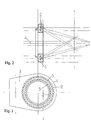
- the arrangement according to the embodiment includes a ring carrier 1, which around the optical axis 4 of a not shown Microscope in the vicinity of the slide or to be microscoped Object is positioned.
- the ring carrier has a printed circuit board or one inside Wiring carrier on that of mechanical fastening and electrical contacting of a variety of light-emitting Diodes 2 is used.
- White light diodes are preferably used as light emitting diodes with a relatively small beam angle.
- a mixed diode assembly red / yellow / orange and / or green
- control electronics located, which is described in more detail with reference to FIG. 4 becomes.
- the light emitting Diodes 2 attached within the ring carrier 1 so that the main beam direction of the diodes 2 to the optical axis 4 of the Systems directed or inclined.
- the concentric ring rows 5 of LEDs 2 and the angle of inclination there is a relatively wide focus range with corresponding optimized lighting properties.
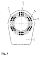
- FIG. 3 illustrates the activation of six selected LED groups or segments, each segment consisting of six adjacent LEDs 2. According to the basic circuit of the LEDs 2 are of course also different from those in FIG. 3 shown segments or groups 6 configurable.
- Each series connection 7 of the LEDs 2 is controlled by a Constant current source 8 driven.
- the inputs of the constant current sources 8 of each channel are located at an output of an 8 bit digital-to-analog converter 9.
- the digital input side the digital-to-analog converter 9 has a control output a microcontroller 10 in connection, which both the brightness control of the LEDs 2 as well as a selection and Control of the segments or selection of the segment size takes over.
- Corresponding operating and adjusting means 11 are used for this available.
- microcontroller 10 can via an interface 12, with the help of a higher-level signal for Function triggering and control can be supplied.
- a feedback circuit 13 provided for compensation on a Analog input of an analog-digital converter 14 leads the Is part of the microcontroller 10 or an external Represents assembly.
- the arrangement is easy to use and over a small size, a much longer life of the Illuminants compared to previous facilities and has a more intelligent lighting control.
Abstract
Description
Die Erfindung betrifft eine Anordnung und ein Verfahren zur
Beleuchtung, insbesondere Auflichtbeleuchtung bei Mikroskopen
mit einem um die optische Achse orientierten Ringträger zur
Aufnahme von Beleuchtungsmitteln, gemäß Oberbegriff des
Patentanspruchs 1 bzw. 3.The invention relates to an arrangement and a method for
Illumination, in particular reflected light illumination in microscopes
with a ring carrier oriented around the optical axis
Inclusion of lighting, according to the preamble of
Aus der deutschen Offenlegungsschrift DE 40 16 264 A1 ist ein Faseroptik-Ringlicht mit Fokussieroptik vorbekannt, welches insbesondere für mikroskopische Arbeitsplätze eingesetzt wird und wobei eine Vielzahl von jeweils einem Segment des Rings zugeordneten Fokussierungselementen vorgesehen ist und zur Schnittpunktveränderung der Teillichtbündel auf der optischen Achse die Fokussierungselemente und/oder die Enden von Lichtleitern radial verschiebbar gestaltet werden.From German published patent application DE 40 16 264 A1 is a Fiber optic ring light with focusing optics previously known, which is used especially for microscopic workplaces and wherein a plurality of one segment each of the ring assigned focusing elements is provided and Change of intersection of the partial light beams on the optical Axis the focusing elements and / or the ends of light guides be designed radially displaceable.
Mit der in der DE 40 16 264 A1 vorgestellten Lösung soll eine Schnittpunktveränderung der Teillichtbündel bezogen auf die optische Achse möglich werden, wobei die Fokussierungselemente beispielsweise kurze Zylinderlinsen sind oder aber auch Kugellinsen zur Anwendung kommen.With the solution presented in DE 40 16 264 A1 a Change in the intersection of the partial light beams in relation to the optical axis are possible, the focusing elements for example, are short cylindrical lenses or spherical lenses come into use.
Die Konstruktion der radialen Verstellung der Fokussierungselemente ist jedoch außerordentlich aufwendig und unbefriedigend, wobei bedingt durch die Zuführung der Strahlungsenergie über Lichtleiter Verluste durch Streuung und im Lichtleitermaterial selbst innenwohnende Dämpfung nicht auszuschließen sind.The construction of the radial adjustment of the focusing elements is extremely complex and unsatisfactory, whereby due to the supply of radiation energy via fiber optic losses due to scattering and in the fiber optic material even internal damping cannot be ruled out are.
Bei der Vorrichtung zur Auflichtbeleuchtung nach DE 28 52 203 A1 wird von symmetrisch um die optische Achse eines abbildenden optischen Elements in einem ringförmigen Bereich angeordneten Lichtleiterendflächen ausgegangen, wobei der die Lichtleiterendflächen enthaltende, zur optischen Achse symmetrisch liegende ringförmige Bereich lichtemittierend und in der hinteren Brennebene und innerhalb des Aperturkegels des abbildenden Elements angeordnet ist. Der die Lichtleiterendflächen enthaltende ringförmige Bereich besteht aus mehreren konzentrischen, ringförmigen Teilbereichen, wobei zur steuerbaren Änderung der Breite des ringförmigen Bereichs den einzelnen Teilbereichen und diesen zugeordneten Lichtleitereingangsgruppen einzeln oder in beliebigen Kombinationen Licht zugeführt werden kann. Zum Zwecke eines steuerbaren Übergangs von Dunkelfeldbeleuchtung in Hellfeldbeleuchtung ist der ringförmige Bereich in Richtung der optischen Achse verschiebbar ausgeführt. Mit der Lehre nach DE 28 52 203 A1 soll eine preiswerte, an praktisch jedem vorhandenen Mikroskop auch nachträglich ohne großen Aufwand anbringbare Dunkelfeldbeleuchtung geschaffen werden, bei der eine Störung der Abbildungsgüte des Mikroskops und ein Auftreten von Hellfeldkomponenten nicht stattfindet. Neben der Möglichkeit, das gesamte Gesichtsfeld des Mikroskopobektivs extrem gleichmäßig auszuleuchten, besteht die Möglichkeit, einzelne, z.B. diametral gegenüberliegende Teile des lichtemittierenden ringförmigen Bereichs anzusteuern, so daß eine Dunkelfeldbeleuchtung mit nur aus einer, zwei oder mehreren Richtungen einfallender Strahlung erzeugt wird.In the device for incident light according to DE 28 52 203 A1 is symmetrical about the optical axis of an imaging optical element arranged in an annular region Light guide end faces, with the light guide end faces containing, symmetrical to the optical axis lying ring-shaped area light-emitting and in the rear focal plane and within the aperture cone of the imaging element is arranged. The light guide end faces containing annular area consists of several concentric, annular sections, with controllable Change the width of the annular area individual sub-areas and associated optical fiber input groups individually or in any combination of light can be supplied. For the purpose of a taxable transition from dark field lighting to bright field lighting is the ring-shaped one Range slidable in the direction of the optical axis executed. With the teaching according to DE 28 52 203 A1 one inexpensive, on practically every existing microscope too Dark field lighting can be retrofitted without much effort be created in which a disturbance of the image quality of the microscope and an appearance of bright field components not taking place. In addition to the possibility of the whole Illuminating the field of view of the microscope lens extremely evenly, there is the possibility of individual, e.g. diametrically opposite parts of the light-emitting annular Control area, so that a dark field lighting with only radiation coming from one, two or more directions is produced.
Konkret wird gemäß DE 28 52 203 A1 auf einen Kunststoffring zurückgegriffen, der mit einer entsprechenden Anzahl von ringförmig angeordneten Löchern versehen ist, in denen die einzelnen Lichtleiter befestigt werden. Die Lichtleiter sind in bestimmte Sektoren sowie in innere und äußere Ringsegmente unterteilt. Die Segmente können über geeignete, zu einer Gruppe zusammengefaßte Schalter in Verbindung mit einer Lichtquelle einzeln oder in Kombination angesteuert werden.Specifically, according to DE 28 52 203 A1 on a plastic ring resorted to that with a corresponding number of ring-shaped holes is provided, in which the individual light guides can be attached. The light guides are in certain sectors as well as inner and outer ring segments divided. The segments can be grouped over suitable ones summarized switches in connection with a light source can be controlled individually or in combination.
Die Konstruktion aus einer Vielzahl von Lichtleitern oder Lichtleiterbündeln, die darüber hinaus einzeln angesteuert werden, ist relativ großbauend und schwer als einfacher Nachrüstbausatz oder Nachrüstbaugruppe zu gestalten.The construction of a variety of light guides or Optical fiber bundles, which are also individually controlled is relatively large and heavy as a simple retrofit kit or retrofit assembly.
Von der Firma Optometron GmbH, München, sind SMT-LED-Beleuchtungen
auch in Form von sogenannten Ringleuchten bekannt.
Diese Ringleuchten können als Auflichtbeleuchtungsmittel
eingesetzt werden, wobei die einzelnen lichtemittierenden
Dioden auf steckbaren Leiterplatten angeordnet sind, um einen
leichten Austausch defekter Elemente zu erreichen. Die Helligkeit
solcher Ringleuchten kann von Hand oder über ein Vorschaltgerät
geregelt werden.
Es hat sich jedoch gezeigt, daß derartige Ringleuchten durch
die eingesetzten Dioden mit einem Abstrahlwinkel im Bereich von
120° keine optimale Ausleuchtung insbesondere beim Mikroskopieren
ermöglichen. Insofern fanden bisher die für die Bildverarbeitszwecke
eingesetzten Ringleuchten keinen Eingang in
die Mikroskopiertechnik bzw. wurden für Mikroskop-Arbeitsplätze
nicht in Betracht gezogen.From the company Optometron GmbH, Munich, SMT LED lights are also known in the form of so-called ring lights. These ring lights can be used as incident light illuminants, the individual light-emitting diodes being arranged on plug-in printed circuit boards in order to make it easy to replace defective elements. The brightness of such ring lights can be controlled manually or using a ballast.
It has been shown, however, that such ring lights, due to the diodes used with a beam angle in the range of 120 °, do not allow optimal illumination, in particular when microscoping. In this respect, the ring lights used for image processing purposes have so far not been used in microscopy technology or have not been considered for microscope workstations.
Weitere Vorrichtungen aus Auflichtbeleuchtung sind aus der Druckschriften US 5 690 417 A, US 5 038 258 A und US 4 893 223 A bekannt.Further devices from reflected light are from the publications US 5 690 417 A, US 5 038 258 A and US 4,893,223 A is known.
Aus dem Vorgenannten ist es daher Aufgabe der Erfindung, eine Anordnung und ein Verfahren zur Beleuchtung, insbesondere Auflichtbeleuchtung bei Mikroskopen nach Art einer Ringleuchte anzugeben, wobei über den gesamten, steuerbaren Helligkeitsbereich eine identische Farbtemperatur zu gewährleisten ist und die Strahlcharakteristik für Mikroskopierzwecke geeignet optimiert wird.From the above, it is therefore an object of the invention to Arrangement and a method for lighting, in particular Incident light illumination in microscopes like a ring light to be specified, covering the entire controllable brightness range an identical color temperature is to be guaranteed and the beam characteristics are suitable for microscopy purposes is optimized.
Die Lösung der Aufgabe der Erfindung erfolgt mit einer Anordnung
gemäß den Merkmalen des Patentanspruchs 1 sowie mit einem
Verfahren nach der Lehre nach Patentanspruch 3.
Der Anspruch 2 stellt eine zweckmäßige Ausgestaltung
und Weiterbildung der Erfindung dar. The object of the invention is achieved with an arrangement according to the features of
Der Grundgedanke der Erfindung besteht darin, von einem an sich bekannten Ringträger auszugehen, der um die optische Achse eines Mikroskops so positioniert wird, daß ein Objektträger mit Objekt ausreichend beleuchtet werden kann. Als Beleuchtungsmittel im Ringträger wird auf dort angeordnete lichtemittierende Halbleiterdioden (LED) zurückgegriffenen, wobei die Hauptstrahlrichtung der Halbleiterdioden zur optischen Achse des Systems hin gerichtet ist. Die Strahlcharakteristik der Dioden ist dabei wesentlich schmaler, als dies bei Dioden der Fall ist, die für Bildverarbeitungs-Ringleuchten eingesetzt werden.The basic idea of the invention is from one in itself known ring bearer to go out around the optical axis a microscope is positioned so that a slide with Object can be illuminated sufficiently. As a means of lighting in the ring carrier is arranged on light-emitting Semiconductor diodes (LED) used, the Main beam direction of the semiconductor diodes to the optical axis of the system is directed. The beam characteristics of the Diodes is much narrower than that of diodes Case is that used for image processing ring lights become.
Durch die eingesetzten LEDs ist die Wärmeentwicklung im Bereich des Objekts bzw. des Objektträgers minimiert und ein günstiger Wirkungsgrad gegeben, wobei die Farbtemperatur im Vergleich zu herkömmlichen Halogenlampen höhere Werte aufweist. Weiterhin bleibt die Farbtemperatur aufgrund der Eigenschaften der LEDs im gesamten Helligkeitsbereich, d.h. auch bei einer Veränderung der Helligkeitswerte gleich.Due to the LEDs used, the heat development in the area the object or the slide is minimized and a cheaper Efficiency given, the color temperature compared to conventional halogen lamps has higher values. Farther the color temperature remains due to the properties of the LEDs in the entire brightness range, i.e. even with a change equal to the brightness values.
Im Ringträger sind mehrere konzentrische Ringreihen von Weißlicht-LEDs fixiert, wobei die LEDs in den Ringreihen im wesentlichen gleiche seitliche Abstände untereinander aufweisen.There are several concentric rows of rings in the ring carrier fixed by white light LEDs, the LEDs in the ring rows in the have essentially the same lateral distances from one another.
Die Längsachsen der LEDs der jeweiligen Ringreihe sind derart zum Mittelpunkt der Anordnung geneigt, daß diese sich in einem Punkt auf oder in der Nähe der Systemachse kreuzen.The longitudinal axes of the LEDs of the respective row of rings are such inclined to the center of the arrangement that this is in one Cross point on or near the system axis.
Die LEDs der Ringleuchte sind einzeln oder in Gruppen ansteuerbar und können darüber hinaus gruppenweise in der Helligkeit geregelt werden.The LEDs of the ring light can be controlled individually or in groups and can also be grouped in brightness be managed.
Bevorzugt werden zum Betreiben an üblicherweise vorhandenen 24 V Gleichspannungsquellen sechs LEDs in Gruppen in Serie geschaltet, wobei jeder Gruppe eine steuerbare Konstantstromquelle zugeordnet ist, welche mit je einem Ausgang eines Digital-Analog-Wandlers in Verbindung steht.Are preferred to operate on usually existing 24 V DC voltage sources six LEDs in groups in series switched, with each group a controllable constant current source is assigned, which has one output each Digital-to-analog converter is connected.
Dem Digital-Analog-Wandler wird ein digitales Steuersignal zum Betreiben der Konstantstromquellen und damit zur Helligkeitsregelung bzw. zur Ansteuerung der LEDs zugeführt.The digital-to-analog converter is a digital control signal Operation of constant current sources and thus for brightness control or to control the LEDs.
Über das Betreiben der LEDs mittels Konstantstrom ist eine gleichmäßige Leuchtdichte und eine hohe Lebensdauer gewährleistet, wobei mittels des Microcontrollers eine segmentweise Ansteuerung der LED-Gruppen in einfacher Weise möglich ist. Darüber hinaus kann dem Microcontroller über eine Schnittstelle ein externes Signal zur Funktionsauslösung und -steuerung zugeführt werden.One is about operating the LEDs using constant current ensures uniform luminance and a long service life, using the microcontroller a segment by segment Control of the LED groups is possible in a simple manner. It can also interface with the microcontroller an external signal for function triggering and control are fed.
Die eingesetzten Konstantstromquellen umfassen Operationsverstärker, welche auf einen Analogeingang eines im Microcontroller integrierten oder diesem zugeordneten Analog-Digital-Wandlers zu Kompensationszwecken rückgekoppelt sind.The constant current sources used include operational amplifiers, which on an analog input one in the microcontroller integrated or assigned to this analog-to-digital converter are fed back for compensation purposes.
Die Ansteuerung von einzelnen LED-Segmenten dient der Kontraststeigerung, indem z.B. eine einseitige Beleuchtung durch Auswahl entsprechender Segmente gewählt wird. Die Segmentgröße wiederum ist variabel wählbar und es besteht die Möglichkeit, eine Ansteuerung quasi dynamisch nach Art eines Lauflichts zu realisieren. Nicht genutzte Segmente können zur Vermeidung von Schattenbildung mit einer geringeren Helligkeit betrieben respektive angesteuert werden. Die Segmentbeleuchtung ist insbesondere bei spiegelnden und/oder strukturierten zu untersuchenden Oberflächen von Vorteil.The control of individual LED segments serves to increase the contrast, e.g. one-sided lighting through Selection of appropriate segments is selected. The segment size again, it can be selected variably and there is the possibility a control quasi dynamically in the manner of a running light realize. Unused segments can be used to avoid Shadow formation operated with a lower brightness respectively controlled. The segment lighting is especially with specular and / or structured ones investigating surfaces is an advantage.
Bei dem erfindungsgemäßen Verfahren zur Auflichtbeleuchtung unter Rückgriff auf die vorbeschriebene Anordnung erfolgt je nach Beleuchtungs-Aufgabenstellung eine Ansteuerung von einer oder mehreren LED-Gruppen bzw. -Segmenten, wobei die Helligkeitswerte jeder Gruppe unterschiedlich, aber auch gleich vorgebbar sind. Über ein dynamisches Betreiben einzelner Segmente nacheinander durch eine entsprechend abgestimmte Steuerung ist eine sich bewegende oder rotierende Lichtquelle nachbildbar. Hierfür kann zum Freihalten der Hände des Experimentators ein Bedienungsfußschalter vorgesehen sein, mit welchem die Steuerung betätigt bzw. ausgelöst wird.In the method for incident light illumination according to the invention depending on the arrangement described above control of one according to lighting task or several LED groups or segments, the brightness values different for each group, but also the same can be specified. About dynamic operation of individuals Segments one after the other by a correspondingly coordinated Control is a moving or rotating light source replicable. For this, to keep the hands of the Experiments can be provided with an operating foot switch which the control is actuated or triggered.
Alle zur Ansteuerung wesentlichen Elemente sind im Ringträger
untergebracht bzw. dort integriert, wobei Bedienmittel ebenfalls
am Ringträger befindlich sind. Die Bedienelemente ermöglichen
ein Ein- und Ausschalten der Auflichtbeleuchtungs-Anordnung,
eine Vorgabe von Helligkeitswerten sowie eine
Auswahl von Segmenten bzw. eine Vorgabe von Segmentgrößen.
Weiterhin ist am Ringträger bzw. Ringträgergehäuse eine
Schnittstelle in Form geeigneter Steckverbinder vorgesehen, um
ein externes, übergeordnetes Signal zur Funktionsauslösung und
-steuerung zuzuführen.
Durch die beschriebene Möglichkeit einer programmgesteuerten
Rotation von Segmenten, Gruppen oder LED-Feldern kann eine sich
verändernde Licht-Schattenbildung realisiert werden, was für
bestimmte Anwendungsfälle in der Mikroskopiertechnik von
Vorteil ist.All elements essential for control are accommodated in the ring carrier or integrated there, with operating means also being located on the ring carrier. The control elements enable the reflected light arrangement to be switched on and off, a specification of brightness values and a selection of segments or a specification of segment sizes. Furthermore, an interface in the form of suitable plug connectors is provided on the ring carrier or ring carrier housing in order to supply an external, higher-level signal for function triggering and control.
The described possibility of program-controlled rotation of segments, groups or LED fields enables a changing light-shadow formation to be implemented, which is advantageous for certain applications in microscope technology.
Die Erfindung soll nachstehend anhand eines Ausführungsbeispiels sowie unter Zuhilfenahme von Figuren näher erläutert werden.The invention is intended to be explained below using an exemplary embodiment and explained with the help of figures become.
Hierbei zeigen:
- Fig. 1
- eine Draufsicht auf den Ringträger mit erkennbaren konzentrischen Ringreihen von Weißlicht-LEDs;
- Fig. 2
- eine Schnittdarstellung des Ringträgers mit zur optischen Achse des Systems geneigten LEDs;
- Fig. 3
- eine Draufsicht auf den Ringträger mit einzeln aktivierten LED-Gruppen bzw. -Segmenten; und
- Fig. 4
- ein Blockschaltbild der Ansteuerelektronik.
- Fig. 1
- a plan view of the ring carrier with recognizable concentric ring rows of white light LEDs;
- Fig. 2
- a sectional view of the ring carrier with LEDs inclined to the optical axis of the system;
- Fig. 3
- a plan view of the ring carrier with individually activated LED groups or segments; and
- Fig. 4
- a block diagram of the control electronics.
Die Anordnung gemäß Ausführungsbeispiel umfaßt einen Ringträger
1, welcher um die optische Achse 4 eines nicht gezeigten
Mikroskops in der Nähe des Objektträgers bzw. des zu mikroskopierenden
Objekts positioniert wird.The arrangement according to the embodiment includes a
Der Ringträger weist im Inneren eine Leiterplatte bzw. einen
Verdrahtungsträger auf, der der mechanischen Befestigung und
elektrischen Kontaktierung einer Vielzahl von lichtemittierenden
Dioden 2 dient.The ring carrier has a printed circuit board or one inside
Wiring carrier on that of mechanical fastening and
electrical contacting of a variety of light-emitting
Als lichtemittierende Dioden kommen vorzugsweise Weißlicht-Dioden mit einem relativ kleinen Abstrahlwinkel zum Einsatz. Zum Erreichen einer niedrigen Farbtemperatur im Bereich < 12000 Kelvin kann eine Diodenmischbestückung (Rot/Gelb/Orange und/oder Grün) vorgesehen sein.White light diodes are preferably used as light emitting diodes with a relatively small beam angle. To achieve a low color temperature in the range <12000 Kelvin can be a mixed diode assembly (red / yellow / orange and / or green) can be provided.
Im Gehäuseteil 3 des Ringträgers 1 ist eine Ansteuerelektronik
befindlich, welche anhand der Fig. 4 noch näher beschrieben
wird. Wie aus der Fig. 2 ersichtlich, sind die lichtemittierenden
Dioden 2 so innerhalb des Ringträgers 1 befestigt, daß
die Hauptstrahlrichtung der Dioden 2 zur optischen Achse 4 des
Systems hin gerichtet respektive geneigt ist. Durch den Abstand
der konzentrischen Ringreihen 5 von LEDs 2 und den Neigungswinkel
ergibt sich ein relativ breiter Fokusbereich mit entsprechend
optimierten Beleuchtungseigenschaften.In the
Beim gezeigten Beispiel sind zwei konzentrische Ringreihen 5
dargestellt, wobei auch mehrere Reihen je nach Mikroskopausbildung
bzw. Beleuchtungsaufgabe denkbar sind.In the example shown there are two concentric rows of
Fig. 3 illustriert die Ansteuerung von sechs ausgewählten LED-Gruppen
bzw. Segmenten, wobei jedes Segment wiederum aus sechs
benachbarten LEDs 2 besteht. Entsprechend der Grundverschaltung
der LEDs 2 sind natürlich auch andere als die in der Fig. 3
gezeigten Segmente oder Gruppen 6 konfigurierbar.3 illustrates the activation of six selected LED groups
or segments, each segment consisting of six
Gemäß Blockschaltbild nach Fig. 4 wird beim Ausführungsbeispiel von einer Reihenschaltung von jeweils sechs LEDs ausgegangen, wobei insgesamt zwölf Kanäle, d.h. zwölf LED-Gruppen gebildet werden.4 is in the exemplary embodiment assume a series connection of six LEDs each, with a total of twelve channels, i.e. twelve LED groups formed become.
Jede Reihenschaltung 7 der LEDs 2 wird von einer steuerbaren
Konstantstromquelle 8 getrieben. Die Eingänge der Konstantstromquellen
8 jedes Kanals liegen jeweils an einem Ausgang
eines 8 Bit Digital-Analog-Wandlers 9. Die digitale Eingangsseite
des Digital-Analog-Wandlers 9 steht mit einem Steuerausgang
eines Microcontrollers 10 in Verbindung, welcher sowohl
die Helligkeitssteuerung der LEDs 2 als auch eine Auswahl und
Ansteuerung der Segmente bzw. Auswahl der Segmentgröße übernimmt.
Hierfür sind entsprechende Bedien- und Stellmittel 11
vorhanden.Each
Weiterhin kann der Microcontroller 10 über eine Schnittstelle
12 verfügen, mit deren Hilfe ein übergeordnetes Signal zur
Funktionsauslösung und -steuerung zugeführt werden kann.Furthermore, the
Um einen Einsatz recht kostengünstiger Operationsverstärker für
die Konstantstromquellen 8 zu ermöglichen, ist eine Rückkoppelschaltung
13 zur Kompensation vorgesehen, die auf einen
Analogeingang eines Analog-Digital-Wandlers 14 führt, der
Bestandteil des Microcontrollers 10 ist oder eine externe
Baugruppe darstellt.To use quite inexpensive operational amplifiers for
To enable the constant
Mit Hilfe der vorgestellten Schaltung ist eine programmgesteuerte, einfache und intelligente Mikroprozessor-Regelung je nach Beleuchtungsaufgabe möglich, wobei die Ansteuerung von einer oder mehreren LED-Gruppen realisierbar ist und unterschiedliche Helligkeitswerte je Gruppe vorgegeben werden können. Weiterhin besteht die Möglichkeit, ein dynamisches Betreiben einzelner Segmente nacheinander im Sinne einer rotierenden oder sich quasi bewegenden Lichtquelle vorzunehmen, wodurch sich aufgrund der Rotation der Segmente eine abwechselnde Licht-Schattenbildung ergibt.With the help of the circuit presented, a program-controlled, simple and intelligent microprocessor control ever possible after lighting task, the control of one or more LED groups can be realized and different ones Brightness values can be specified for each group can. There is also the possibility of a dynamic Operating individual segments one after the other in the sense of a rotating or quasi-moving light source, which causes an alternating due to the rotation of the segments Light-shadow formation results.
Alles in allem kann mit Hilfe der vorgestellten Anordnung in besonders einfacher und effektiver Weise eine Beleuchtung, insbesondere Auflichtbeleuchtung für Mikroskope realisiert werden, wobei die Anordnung einfach zu bedienen ist und über eine geringe Baugröße, eine wesentlich höhere Lebensdauer der Beleuchtungsmittel im Vergleich zu bisherigen Einrichtungen und eine intelligentere Lichtsteuerung verfügt.All in all, with the help of the arrangement presented in lighting in a particularly simple and effective manner, in particular reflected light illumination for microscopes be, the arrangement is easy to use and over a small size, a much longer life of the Illuminants compared to previous facilities and has a more intelligent lighting control.
- 11
- RingträgerRingbearer
- 22
- LEDLED
- 33
- Gehäuseteilhousing part
- 44
- optische Achseoptical axis
- 55
- konzentrische Ringreihenconcentric rows of rings
- 66
- Segmente/GruppenSegments / groups
- 77
- Reihenschaltung der LEDSeries connection of the LED
- 88th
- KonstantstromquelleConstant current source
- 99
- Digital-Analog-WandlerDigital to analog converter
- 1010
- Microcontrollermicrocontrollers
- 1111
- Bedien- bzw. StellmittelOperating or adjusting means
- 1212
- Schnittstelleinterface
- 1313
- RückkopplungsschaltungFeedback circuit
- 1414
- Analog-Digital-WandlerAnalog to digital converter
Claims (3)
- An illumination arrangement, in particular vertical illumination in microscopes, comprising a planar ring carrier (1) oriented about the optical axis of the microscope and for receiving illumination means, said illumination means being small radiation angle light-emitting semiconductor diodes (LED 2) present in the ring carrier in a plurality of concentric ring rows, and the main radiation direction of the semiconductor diodes being directed towards the optical axis (4), the LEDs (2) in the ring rows have essentially identical lateral spacings between each other, with the LEDs (2) being drivable in groups by means of a switching circuit and being controllable in brightness,
characterized in that
the LEDs (2) in the groups are connected in series, with each group associated with an adjustable stabilized power supply (8), which is in connection in each case with an output of a D/A converter (9), and moreover, a digital control signal for driving the stabilized power supplies (8) is supplied to the D/A converter (9), with the digital control signal being provided by a microcontroller (10), the stabilized power supplies (8) comprising operational amplifiers, which, for compensation reasons, are fed back to an analog input of an A/D converter (14) integrated in the microcontroller (10) or associated to same, and the LEDs (2) are white light diodes. - Arrangement according to claim 1, characterized in that an external overriding signal for function driving and controlling, including default setting of the brightness, may be supplied to the microcontroller (10) via an interface.
- Method of vertically illuminating with an arrangement according to claim 1 or 2, characterized in that, depending on the setting of the tasks for the illumination, a driving of one or several LED group/s takes place, with the brightness values of each group being differently pre-settable, and through a dynamic operation, a quasi moving or rotating light source may be reproduced, and, moreover, for avoiding shadow formations with reflecting and/or textured surfaces, groups which are not used on the illumination part, are driven at low brightness.
Applications Claiming Priority (4)
| Application Number | Priority Date | Filing Date | Title |
|---|---|---|---|
| DE10020454 | 2000-04-26 | ||
| DE10020454 | 2000-04-26 | ||
| DE10030772 | 2000-06-23 | ||
| DE10030772A DE10030772B4 (en) | 2000-04-26 | 2000-06-23 | Incident light illumination in microscopes with a ring carrier oriented around the optical axis for receiving illuminants |
Publications (2)
| Publication Number | Publication Date |
|---|---|
| EP1150154A1 EP1150154A1 (en) | 2001-10-31 |
| EP1150154B1 true EP1150154B1 (en) | 2003-03-26 |
Family
ID=26005473
Family Applications (1)
| Application Number | Title | Priority Date | Filing Date |
|---|---|---|---|
| EP01110318A Expired - Lifetime EP1150154B1 (en) | 2000-04-26 | 2001-04-26 | Device and method for annular illumination, especially for bright field illumination of microscopes |
Country Status (2)
| Country | Link |
|---|---|
| EP (1) | EP1150154B1 (en) |
| AT (1) | ATE235704T1 (en) |
Cited By (7)
| Publication number | Priority date | Publication date | Assignee | Title |
|---|---|---|---|---|
| DE102004026630B4 (en) * | 2004-05-27 | 2007-05-03 | Doctorseyes Gmbh | Method and device for macro photography |
| DE102007006584B3 (en) * | 2007-02-09 | 2008-06-19 | Leica Microsystems (Schweiz) Ag | Illumination device for microscope, particularly trans-illumination device for stereo microscope, comprises carrier element on which point light sources are arranged and holder, which is provided for receiving each of point light sources |
| US7602483B2 (en) | 2005-07-06 | 2009-10-13 | Chromasens Gmbh | Device for dark field illumination and method for optically scanning of object |
| DE102008035959A1 (en) * | 2008-07-31 | 2010-03-04 | Doctorseyes Gmbh | Device for production of digital macro photographs of tooth sector in mouth area, has digital camera, lighting device and lighting control, where lighting device has diffused radiating ring light with light emitting diodes |
| CN1908721B (en) * | 2005-08-02 | 2010-06-16 | 莱卡微系统(瑞士)股份公司 | Stereo microscope system with incident illumination device |
| DE102017119828A1 (en) * | 2017-08-29 | 2019-02-28 | Leibniz-Institut für Werkstofforientierte Technologien - IWT | Work machine with a rotating machine part holder, in particular a machine tool with a rotating tool holder, method for adjusting a machine part, in particular a tool, and ring light for such a machine |
| DE102011102610B4 (en) | 2010-06-22 | 2021-09-23 | G. Drexl Abwassertechnik Gmbh & Co. Kg | Light module for a sewer camera and associated sewer camera |
Families Citing this family (18)
| Publication number | Priority date | Publication date | Assignee | Title |
|---|---|---|---|---|
| DE50115561D1 (en) | 2001-11-26 | 2010-08-26 | X Rite Europe Gmbh | Spectrophotometer and use thereof |
| DE10246889B4 (en) † | 2002-10-08 | 2004-08-19 | Karl Kaps Gmbh & Co. Kg | Lighting device for an optical magnification device and optical magnification device |
| EP1411290A1 (en) * | 2002-10-18 | 2004-04-21 | Altman Stage Lighting Co.,Inc. New York Corporation | Diode lighting system |
| DE10256270A1 (en) * | 2002-12-03 | 2004-06-24 | Carl Zeiss Sms Gmbh | Microscope with UV semiconductor light source |
| DE20304412U1 (en) | 2003-03-19 | 2003-06-12 | Schott Glas | Control unit for number of lighting units used in a mixed mode for microscopy lighting |
| WO2005029150A1 (en) * | 2003-09-25 | 2005-03-31 | Leica Microsystems Cms Gmbh | Lens for evanescent wave illumination and corresponding microscope |
| DE102004051548A1 (en) * | 2004-10-20 | 2006-05-04 | Carl Zeiss Jena Gmbh | Illumination device for microscopes |
| DE102005029119A1 (en) | 2005-06-23 | 2006-12-28 | Carl Zeiss Jena Gmbh | Illumination device, especially for microscopes, has individual light sources designed as discrete cells |
| US7433026B2 (en) * | 2005-12-20 | 2008-10-07 | Cytyc Corporation | Microscope with LED illumination source |
| US7561329B2 (en) * | 2006-12-14 | 2009-07-14 | Cytyc Corporation | Illumination source for stained biological samples |
| DE102008012585A1 (en) | 2008-03-05 | 2009-09-24 | Carl Zeiss Microlmaging Gmbh | Objective with incident light illumination for light microscopes |
| EP2204686B9 (en) | 2008-12-30 | 2012-11-14 | Cellavision AB | Analyser for optical analysis of a biological specimen |
| DE102009038027A1 (en) * | 2009-08-18 | 2011-02-24 | Carl Zeiss Microimaging Gmbh | Lighting device for microscopes and macroscopes |
| EP2564111B1 (en) * | 2010-04-28 | 2022-01-05 | KLA-Tencor Corporation | Ring light illuminator and beam shaper for ring light illuminator |
| DE102013006996A1 (en) * | 2013-04-19 | 2014-10-23 | Carl Zeiss Microscopy Gmbh | Method for illuminating an object in a digital light microscope, digital light microscope and bright field incident illumination device for a digital light microscope |
| DE102014101219A1 (en) * | 2014-01-31 | 2015-08-06 | Carl Zeiss Ag | Illuminating device for Fourier ptychography |
| DE102014202679A1 (en) * | 2014-02-13 | 2015-08-27 | Dr. Wirth Grafische Technik Gmbh & Co. Kg | Apparatus and method for generating image information from an object to be detected |
| CN105739075B (en) * | 2016-04-18 | 2018-10-02 | 麦克奥迪实业集团有限公司 | A kind of falling based on annular LED penetrates bright dark field microscope and its means of illumination |
Citations (2)
| Publication number | Priority date | Publication date | Assignee | Title |
|---|---|---|---|---|
| US4893223A (en) * | 1989-01-10 | 1990-01-09 | Northern Telecom Limited | Illumination devices for inspection systems |
| US5038258A (en) * | 1989-03-02 | 1991-08-06 | Carl-Zeiss-Stiftung | Illuminating arrangement for illuminating an object with incident light |
Family Cites Families (3)
| Publication number | Priority date | Publication date | Assignee | Title |
|---|---|---|---|---|
| DE2852203C3 (en) | 1978-12-02 | 1982-03-11 | Ibm Deutschland Gmbh, 7000 Stuttgart | Light guide device for an imaging device operated with incident light |
| DE4016264A1 (en) | 1990-05-19 | 1991-11-21 | Faseroptik Henning Gmbh & Co | FIBER OPTIC RING LIGHT |
| US5690417A (en) * | 1996-05-13 | 1997-11-25 | Optical Gaging Products, Inc. | Surface illuminator with means for adjusting orientation and inclination of incident illumination |
-
2001
- 2001-04-26 AT AT01110318T patent/ATE235704T1/en not_active IP Right Cessation
- 2001-04-26 EP EP01110318A patent/EP1150154B1/en not_active Expired - Lifetime
Patent Citations (2)
| Publication number | Priority date | Publication date | Assignee | Title |
|---|---|---|---|---|
| US4893223A (en) * | 1989-01-10 | 1990-01-09 | Northern Telecom Limited | Illumination devices for inspection systems |
| US5038258A (en) * | 1989-03-02 | 1991-08-06 | Carl-Zeiss-Stiftung | Illuminating arrangement for illuminating an object with incident light |
Cited By (7)
| Publication number | Priority date | Publication date | Assignee | Title |
|---|---|---|---|---|
| DE102004026630B4 (en) * | 2004-05-27 | 2007-05-03 | Doctorseyes Gmbh | Method and device for macro photography |
| US7602483B2 (en) | 2005-07-06 | 2009-10-13 | Chromasens Gmbh | Device for dark field illumination and method for optically scanning of object |
| CN1908721B (en) * | 2005-08-02 | 2010-06-16 | 莱卡微系统(瑞士)股份公司 | Stereo microscope system with incident illumination device |
| DE102007006584B3 (en) * | 2007-02-09 | 2008-06-19 | Leica Microsystems (Schweiz) Ag | Illumination device for microscope, particularly trans-illumination device for stereo microscope, comprises carrier element on which point light sources are arranged and holder, which is provided for receiving each of point light sources |
| DE102008035959A1 (en) * | 2008-07-31 | 2010-03-04 | Doctorseyes Gmbh | Device for production of digital macro photographs of tooth sector in mouth area, has digital camera, lighting device and lighting control, where lighting device has diffused radiating ring light with light emitting diodes |
| DE102011102610B4 (en) | 2010-06-22 | 2021-09-23 | G. Drexl Abwassertechnik Gmbh & Co. Kg | Light module for a sewer camera and associated sewer camera |
| DE102017119828A1 (en) * | 2017-08-29 | 2019-02-28 | Leibniz-Institut für Werkstofforientierte Technologien - IWT | Work machine with a rotating machine part holder, in particular a machine tool with a rotating tool holder, method for adjusting a machine part, in particular a tool, and ring light for such a machine |
Also Published As
| Publication number | Publication date |
|---|---|
| ATE235704T1 (en) | 2003-04-15 |
| EP1150154A1 (en) | 2001-10-31 |
Similar Documents
| Publication | Publication Date | Title |
|---|---|---|
| EP1150154B1 (en) | Device and method for annular illumination, especially for bright field illumination of microscopes | |
| DE19653234B4 (en) | Surface illuminator with means for adjusting the orientation and inclination of incident lighting | |
| EP1722157B1 (en) | Surgical lamp with zone-related intensity control | |
| DE4228895C2 (en) | Motor vehicle lighting device with multiple semiconductor light sources | |
| DE60217523T2 (en) | ADJUSTABLE OPTICS FOR SPOT MODULE | |
| EP1162638A2 (en) | Arrangement for illuminating a control knob of an input device by transparency | |
| EP1588895B1 (en) | LED lighting device | |
| WO2013056928A1 (en) | Semiconductor light device comprising a lens having a light deflection structure | |
| DE10030772B4 (en) | Incident light illumination in microscopes with a ring carrier oriented around the optical axis for receiving illuminants | |
| DE19837797A1 (en) | Surface illuminator | |
| EP2302295B1 (en) | Assembly for emitting light with light source and optical element | |
| DE102004023358B3 (en) | Lighting arrangement for a stage comprises a first adjusting element interacting with lighting bodies and moving on a housing to simultaneously pivot the lighting bodies and a second adjusting element | |
| DE10208447C1 (en) | Magnifying optical system used as viewing aid has LED illumination element with variable color output | |
| EP0913625A2 (en) | Signalling light | |
| EP3274627B1 (en) | Signalling apparatus for command and/or reporting devices | |
| DE102016120256A1 (en) | LIGHTING DEVICE WITH VARIABLE LIGHT DISTRIBUTION | |
| EP1861743B1 (en) | Annular lamp for an optical or medical device | |
| EP3583352B1 (en) | Lighting unit and method for controlling emission characteristics thereof | |
| DE102010031678B4 (en) | Fast variable angle of incidence illumination for machine vision inspection system | |
| EP3081855B1 (en) | Spotlight | |
| EP3686480B1 (en) | Light emitting assembly with variable light emission characteristics | |
| DE10064544A1 (en) | Ring light has annular bearer for attachment to objective and annular light source on bearer in form of number of light emitting diodes with associated annular circuit board | |
| EP3371511A2 (en) | Lighting device | |
| DE102019218167A1 (en) | Component-integrated lighting module with at least one optical fiber | |
| DE102020112237A1 (en) | lamp |
Legal Events
| Date | Code | Title | Description |
|---|---|---|---|
| PUAI | Public reference made under article 153(3) epc to a published international application that has entered the european phase |
Free format text: ORIGINAL CODE: 0009012 |
|
| AK | Designated contracting states |
Kind code of ref document: A1 Designated state(s): AT BE CH CY DE DK ES FI FR GB GR IE IT LI LU MC NL PT SE TR |
|
| AX | Request for extension of the european patent |
Free format text: AL;LT;LV;MK;RO;SI |
|
| 17P | Request for examination filed |
Effective date: 20011221 |
|
| 17Q | First examination report despatched |
Effective date: 20020228 |
|
| AKX | Designation fees paid |
Free format text: AT BE CH CY DE DK ES FI FR GB GR IE IT LI LU MC NL PT SE TR |
|
| GRAH | Despatch of communication of intention to grant a patent |
Free format text: ORIGINAL CODE: EPIDOS IGRA |
|
| RAP1 | Party data changed (applicant data changed or rights of an application transferred) |
Owner name: COBRA ELECTRONIC GMBH |
|
| GRAH | Despatch of communication of intention to grant a patent |
Free format text: ORIGINAL CODE: EPIDOS IGRA |
|
| GRAA | (expected) grant |
Free format text: ORIGINAL CODE: 0009210 |
|
| AK | Designated contracting states |
Designated state(s): AT BE CH CY DE DK ES FI FR GB GR IE IT LI LU MC NL PT SE TR |
|
| PG25 | Lapsed in a contracting state [announced via postgrant information from national office to epo] |
Ref country code: IE Free format text: LAPSE BECAUSE OF FAILURE TO SUBMIT A TRANSLATION OF THE DESCRIPTION OR TO PAY THE FEE WITHIN THE PRESCRIBED TIME-LIMIT Effective date: 20030326 Ref country code: NL Free format text: LAPSE BECAUSE OF FAILURE TO SUBMIT A TRANSLATION OF THE DESCRIPTION OR TO PAY THE FEE WITHIN THE PRESCRIBED TIME-LIMIT Effective date: 20030326 Ref country code: GR Free format text: LAPSE BECAUSE OF FAILURE TO SUBMIT A TRANSLATION OF THE DESCRIPTION OR TO PAY THE FEE WITHIN THE PRESCRIBED TIME-LIMIT Effective date: 20030326 Ref country code: TR Free format text: LAPSE BECAUSE OF FAILURE TO SUBMIT A TRANSLATION OF THE DESCRIPTION OR TO PAY THE FEE WITHIN THE PRESCRIBED TIME-LIMIT Effective date: 20030326 Ref country code: FI Free format text: LAPSE BECAUSE OF FAILURE TO SUBMIT A TRANSLATION OF THE DESCRIPTION OR TO PAY THE FEE WITHIN THE PRESCRIBED TIME-LIMIT Effective date: 20030326 |
|
| REG | Reference to a national code |
Ref country code: GB Ref legal event code: FG4D Free format text: NOT ENGLISH |
|
| REG | Reference to a national code |
Ref country code: CH Ref legal event code: EP |
|
| PG25 | Lapsed in a contracting state [announced via postgrant information from national office to epo] |
Ref country code: LU Free format text: LAPSE BECAUSE OF NON-PAYMENT OF DUE FEES Effective date: 20030426 Ref country code: AT Free format text: LAPSE BECAUSE OF NON-PAYMENT OF DUE FEES Effective date: 20030426 Ref country code: CY Free format text: LAPSE BECAUSE OF FAILURE TO SUBMIT A TRANSLATION OF THE DESCRIPTION OR TO PAY THE FEE WITHIN THE PRESCRIBED TIME-LIMIT Effective date: 20030426 |
|
| PG25 | Lapsed in a contracting state [announced via postgrant information from national office to epo] |
Ref country code: BE Free format text: LAPSE BECAUSE OF NON-PAYMENT OF DUE FEES Effective date: 20030430 Ref country code: MC Free format text: LAPSE BECAUSE OF NON-PAYMENT OF DUE FEES Effective date: 20030430 |
|
| REF | Corresponds to: |
Ref document number: 50100124 Country of ref document: DE Date of ref document: 20030430 Kind code of ref document: P |
|
| REG | Reference to a national code |
Ref country code: IE Ref legal event code: FG4D Free format text: GERMAN |
|
| PG25 | Lapsed in a contracting state [announced via postgrant information from national office to epo] |
Ref country code: DK Free format text: LAPSE BECAUSE OF FAILURE TO SUBMIT A TRANSLATION OF THE DESCRIPTION OR TO PAY THE FEE WITHIN THE PRESCRIBED TIME-LIMIT Effective date: 20030626 Ref country code: SE Free format text: LAPSE BECAUSE OF FAILURE TO SUBMIT A TRANSLATION OF THE DESCRIPTION OR TO PAY THE FEE WITHIN THE PRESCRIBED TIME-LIMIT Effective date: 20030626 Ref country code: PT Free format text: LAPSE BECAUSE OF FAILURE TO SUBMIT A TRANSLATION OF THE DESCRIPTION OR TO PAY THE FEE WITHIN THE PRESCRIBED TIME-LIMIT Effective date: 20030626 |
|
| GBT | Gb: translation of ep patent filed (gb section 77(6)(a)/1977) |
Effective date: 20030801 |
|
| NLV1 | Nl: lapsed or annulled due to failure to fulfill the requirements of art. 29p and 29m of the patents act | ||
| PG25 | Lapsed in a contracting state [announced via postgrant information from national office to epo] |
Ref country code: ES Free format text: LAPSE BECAUSE OF FAILURE TO SUBMIT A TRANSLATION OF THE DESCRIPTION OR TO PAY THE FEE WITHIN THE PRESCRIBED TIME-LIMIT Effective date: 20030930 |
|
| BERE | Be: lapsed |
Owner name: *COBRA ELECTRONIC G.M.B.H. Effective date: 20030430 |
|
| REG | Reference to a national code |
Ref country code: IE Ref legal event code: FD4D Ref document number: 1150154E Country of ref document: IE |
|
| ET | Fr: translation filed | ||
| PLBE | No opposition filed within time limit |
Free format text: ORIGINAL CODE: 0009261 |
|
| STAA | Information on the status of an ep patent application or granted ep patent |
Free format text: STATUS: NO OPPOSITION FILED WITHIN TIME LIMIT |
|
| 26N | No opposition filed |
Effective date: 20031230 |
|
| PGFP | Annual fee paid to national office [announced via postgrant information from national office to epo] |
Ref country code: GB Payment date: 20050414 Year of fee payment: 5 |
|
| PGFP | Annual fee paid to national office [announced via postgrant information from national office to epo] |
Ref country code: FR Payment date: 20050419 Year of fee payment: 5 |
|
| PG25 | Lapsed in a contracting state [announced via postgrant information from national office to epo] |
Ref country code: LI Free format text: LAPSE BECAUSE OF NON-PAYMENT OF DUE FEES Effective date: 20050430 Ref country code: CH Free format text: LAPSE BECAUSE OF NON-PAYMENT OF DUE FEES Effective date: 20050430 |
|
| REG | Reference to a national code |
Ref country code: CH Ref legal event code: PL |
|
| PG25 | Lapsed in a contracting state [announced via postgrant information from national office to epo] |
Ref country code: GB Free format text: LAPSE BECAUSE OF NON-PAYMENT OF DUE FEES Effective date: 20060426 |
|
| PGFP | Annual fee paid to national office [announced via postgrant information from national office to epo] |
Ref country code: IT Payment date: 20060430 Year of fee payment: 6 |
|
| GBPC | Gb: european patent ceased through non-payment of renewal fee |
Effective date: 20060426 |
|
| REG | Reference to a national code |
Ref country code: FR Ref legal event code: ST Effective date: 20061230 |
|
| PG25 | Lapsed in a contracting state [announced via postgrant information from national office to epo] |
Ref country code: FR Free format text: LAPSE BECAUSE OF NON-PAYMENT OF DUE FEES Effective date: 20060502 |
|
| PGFP | Annual fee paid to national office [announced via postgrant information from national office to epo] |
Ref country code: DE Payment date: 20070628 Year of fee payment: 7 |
|
| PG25 | Lapsed in a contracting state [announced via postgrant information from national office to epo] |
Ref country code: DE Free format text: LAPSE BECAUSE OF NON-PAYMENT OF DUE FEES Effective date: 20081101 |
|
| PG25 | Lapsed in a contracting state [announced via postgrant information from national office to epo] |
Ref country code: IT Free format text: LAPSE BECAUSE OF NON-PAYMENT OF DUE FEES Effective date: 20070426 |