EP1151847A1 - Device for fitting a sleve on a container and method of applying the device - Google Patents
Device for fitting a sleve on a container and method of applying the device Download PDFInfo
- Publication number
- EP1151847A1 EP1151847A1 EP01201420A EP01201420A EP1151847A1 EP 1151847 A1 EP1151847 A1 EP 1151847A1 EP 01201420 A EP01201420 A EP 01201420A EP 01201420 A EP01201420 A EP 01201420A EP 1151847 A1 EP1151847 A1 EP 1151847A1
- Authority
- EP
- European Patent Office
- Prior art keywords
- bush
- sleeve
- disc
- container
- wall
- Prior art date
- Legal status (The legal status is an assumption and is not a legal conclusion. Google has not performed a legal analysis and makes no representation as to the accuracy of the status listed.)
- Granted
Links
Images
Classifications
-
- B—PERFORMING OPERATIONS; TRANSPORTING
- B29—WORKING OF PLASTICS; WORKING OF SUBSTANCES IN A PLASTIC STATE IN GENERAL
- B29C—SHAPING OR JOINING OF PLASTICS; SHAPING OF MATERIAL IN A PLASTIC STATE, NOT OTHERWISE PROVIDED FOR; AFTER-TREATMENT OF THE SHAPED PRODUCTS, e.g. REPAIRING
- B29C63/00—Lining or sheathing, i.e. applying preformed layers or sheathings of plastics; Apparatus therefor
- B29C63/38—Lining or sheathing, i.e. applying preformed layers or sheathings of plastics; Apparatus therefor by liberation of internal stresses
- B29C63/42—Lining or sheathing, i.e. applying preformed layers or sheathings of plastics; Apparatus therefor by liberation of internal stresses using tubular layers or sheathings
- B29C63/423—Lining or sheathing, i.e. applying preformed layers or sheathings of plastics; Apparatus therefor by liberation of internal stresses using tubular layers or sheathings specially applied to the mass-production of externally coated articles, e.g. bottles
-
- B—PERFORMING OPERATIONS; TRANSPORTING
- B65—CONVEYING; PACKING; STORING; HANDLING THIN OR FILAMENTARY MATERIAL
- B65C—LABELLING OR TAGGING MACHINES, APPARATUS, OR PROCESSES
- B65C3/00—Labelling other than flat surfaces
- B65C3/06—Affixing labels to short rigid containers
- B65C3/065—Affixing labels to short rigid containers by placing tubular labels around the container
Definitions
- the invention relates to a device for fitting a sleeve on a container such as a bottle or a similar object, said device comprising a double-walled bush with its inner wall perforated and the interior annular space of the bush being connectable to a vacuum line for generating underpressure within the interior space and sucking a sleeve inserted in said bush against the inner wall so that a container can be brought into the sleeve whereupon the connection with the vacuum line is disconnected.
- the object of the invention is to remove these difficulties and to that end provides for, that the device comprises a number of bushes the inner and outer wall of each bush being fixedly connected to each other and the axes of said bushes being directed vertically, positioning means for the bushes being present so that a sleeve, obtained by cutting-off a part of a flattened tube drawn from a supply roller, can be slid into the bush in vertical direction and can be sucked against the inner wall of it, whereupon the positioning means can slide the bush and the sleeve across a container and the connection with the vacuum line can be disconnected.
- the double-walled bush need only be moved up and down, in such a way that it is situated above a container and subsequently is moved downwards so that it will be positioned around the container. Then, the underpressure is released and the bush is returned to its initial position.
- means for blowing hot air onto the lower edge of the sleeve when the bush is in its lowermost position on the container can be provided for.
- a stationary stop member for the sleeve will be present underneath the bush, at the position where a sleeve is inserted into it.
- the sleeve can be brought at the appropriate position within the bush before a vacuum is generated in the internal space of the bush.
- Such a stop member can be in the shape of a substantially horizontally extending rod being situated at some distance from the bush at the position where the sleeve is inserted into said bush, and which, on moving the bush or the rod substantially in horizontal direction, will closely engage the bottom side of the bush.
- the device will comprise a turret in which containers are brought onto a rotating disc from which disc they will be removed after a certain rotation of said disc, the number of bushes being at least equal to the number of containers which can be present on said disc and the guiding member of each bush being slidable along a substantially vertically extending guide connected to the disc.
- the bushes are moved in vertical direction, to which end a curve track fixedly mounted in the device is used, against which the guide member of the bush is drawn downwards by means of a spring, in which the sleeve is inserted into the bush at almost the highest point of the track.
- the vacuum line extending to a bush should rotate along with the disc of the turret, it can be provided for, that the vacuum lines of the bushes situated on the turret are connected to an annular vacuum switching plate extending around the rotary shaft of the disc of the turret and moving along with it, or being part of it, an opening in the vacuum switching plate during part of its rotation communicating with a stationary arranged vacuum chamber situated underneath the switching plate.
- the means for keeping a container in its place on the disc of the turret can be in the form of openings in the disc which can be connected to at least one vacuum chamber situated below the disc. Often it might be sufficient to hold the containers only when bringing them onto the disc and removing them from it.
- each container is positioned on a platform being mounted movably in vertical direction in the disc of the turret and being provided with a connection for a vacuum line, said platform supporting only the central part of the bottom of a container.
- the disc has a number of openings for each container, to wit at least three, through which pins can be slid from below till beyond the surface of the disc, which will be situated around the container, with the pins being mounted on a support member being movable in vertical direction by operating means.
- the operating means for moving the pin-bearing support member up and down can be in the form of a curve track fixedly mounted below the disc of the turret.
- the means for holding the container on the disc must be activated immediately after the container has been placed on the disc. After that, the means might be switched-off depending on the design of the turret.
- the inner wall of the bush need not necessarily have a cylindrical shape. It can also have a more rectangular or oval shape and thus be suitable for bringing a sleeve onto a container having a corresponding cross-sectional shape. Generally, then it will be necessary that a sleeve is inserted into the bush in a certain way. Namely, a print present on the sleeve then will have to be visible on the container in the desired way. Thus, the sleeve should be guided more carefully on insertion into the bush.
- the invention also comprises a method of using the device described above, said method being characterized in that a sleeve is cut-off from a flattened plastic tube drawn from a supply roller, said sleeve being slid vertically into a double-walled bush having its inner wall perforated, air being drawn from the space around the inner wall so that the sleeve is pressed against the inner wall, the bush being slid across a container, the underpressure in the space being removed, a stream of hot air being directed at the lower edge of the sleeve and the bush being returned to its initial position.
- FR-A-2 669 908 describes a device in which two resilient plates, being flat in their starting positions, with a sleeve between them, are received between two pairs of clamping jaws.
- the sleeve is drawn against the plates in that the plates are provided with a number of openings to which pipes connected to a vacuum source are connected.
- the clamping jaws are pushed towards each other to bring the plates in a bent shape so that together they bring the sleeve in a somewhat circular shape.
- US-A-3 852 940 shows an automatic cap sealing device for applying a tubular element of thermally contractive synthetic resin to the capped mouth portion of a bottle.
- a cap is raised by a hollow pipe under vacuum and is brought in the desired shape by other suction means. Subsequently, the pipe is moved in vertical direction towards the mouth portion of the bottle for mounting the cap on it.
- the bottles are moved through the device by means of a turret.
- the device illustrated in the drawings comprises means for cutting a part, in the shape of a sleeve, from a flattened tube drawn from a supply roller.
- Such a means is known from EP-B-0 109 105 so that discussion thereof is considered to be superfluous.
- the cut-off sleeve 1 is inserted into a bush 2, consisting of a perforated inner wall 3 and an outer wall 4 connected to it, so that an interior, closed-off space 5 is situated between both walls 3 and 4.
- the inner wall 3 can be provided with at least one slot 6 facing outwards.
- the inner and outer walls have been illustrated separately in figure 1.
- a stop member 7 is fixedly mounted there.
- the stop member 7 is in the form of a substantially horizontally extending rod 8 which, when the sleeve 1 is inserted into the bush 2, will be situated at some distance below the bush and will closely engage the bottom of the bush when the latter is moved substantially in horizontal direction.
- the rod 8 can be sligthly bent, for example.
- the rod will be connected to a part of the frame 9 of the device in a way not further indicated.
- the device comprises a turret which is formed by a disc 10 consisting of a number of parts, said disc having a lowermost annular part 10 a being provided with a toothing 11, so that the disc can be rotated by means of a motor-driven gear wheel 12.
- the annular part 10a is provided with an inner edge 10b cooperating with rollers 10c, being rotatably mounted on the frame 9.
- a conveyor belt 13 extends, by which containers 14 can be supplied to the disc.
- the containers 14 are brought at the appropriate mutual distance.
- two star wheels 16 are employed for bringing the containers 14 onto the disc 10 and removing them from it.
- the direction of rotation of the disc 10 and of the star wheels 16 is indicated by arrows.
- the rotation of the worm shaft 15 and of the star wheels 16 is synchronized with the rotation of the disc 10.
- each bush 2 is provided with a guiding member 17 which is slidable along a vertically extending guide 18 connected to the disc 10.
- a curve track 19 fixedly connected to the frame 9 of the device is used for vertical movement of the bushes 2.
- the curve track can be in the shape of a cylindrical plate, as seen in plan view, which however need not extend across the entire circumference of the disc 10.
- the guiding member 17 of a bush 2 lies, possibly with intervention of a roller, against the the upper edge 20 of the curve track 19.
- the guiding member 17 of the bush 2 is pulled downwards against the upper edge 20 of the curve track 19 by means of a spring 21.
- an opening in the connecting plate will be in communication with a fixedly arranged vacuum chamber 31 situated below it, during a portion of the revolution of the plate.
- a fixedly arranged vacuum chamber 31 situated below it, during a portion of the revolution of the plate.
- a blowing nozzle 24 can be used, by which hot air is blown onto the lower edge of the sleeve 1, so that the sleeve is shrunk around the container 14.
- the blowing nozzle need not be on the place shown in figure 1.
- the bush 2 can start moving upwards under the influence of the curve track 19. It will be obvious, that the bush 2 can be in its lowermost position across a certain part of a revolution of the disc 10, so that basically, the curve track 19 can be omitted there.
- a container 14 is kept in the appropriate position, so that a bush 2 slides across the container 14 during its downwards movement and does not contact the container in such a way that it could be pushed over.
- the container 14 can be held in that the disc 10 has an opening 25 for each container, which opening is connected to a vacuum chamber 26 extending across at least a part of the circumference of the disc 10.
- figure 2 basically shows an inner circumference part of the disc 10, in flattened shape, with the curve track 19 and some further parts.
- openings 27 can be provided in the disc 10, around the location where a container will be situated.
- pins 28 can be led upwards when a container 14 is situated at its place on the disc 10.
- the pins 28 can e.g. be provided on a support member 29 being movable in vertical direction, by a curve track 30 fixedly mounted below the disc of the turret.
- Fig. 3 shows the possibility of providing the outer wall 4 of the bush with an extended portion 32 for forming a chamber 33 to which hot air can be supplied by means of a line 34 in order to shrink a sleeve 1 when it has been brought around a container.
- a container 14 is positioned on a platform 35 being smaller than the bottom of the container and being vertically movable in respect of the disc 10.
- the platform 35 is mounted on a pipe 36 being guided by the disc 10 and having its lower end carrying a roller 37 moving across a curve track 38.
- Via the pipe 36 the bottom of the container 14 is drawn against the platform 35.
- the sleeve 1 can now extend up to some distance below the bottom of the container and will be shrunk onto the container below the bottom after applying of the sleeve.
Abstract
Description
- The invention relates to a device for fitting a sleeve on a container such as a bottle or a similar object, said device comprising a double-walled bush with its inner wall perforated and the interior annular space of the bush being connectable to a vacuum line for generating underpressure within the interior space and sucking a sleeve inserted in said bush against the inner wall so that a container can be brought into the sleeve whereupon the connection with the vacuum line is disconnected.
- Such a device is known from US-A-3 841 940. With this known device, the axis of the bush extends almost horizontally and the upper part of the inner wall can be moved vertically in relation to the lower part. By this it should be guaranteed that the sleeve, being brought into the bush in a more or less folded position, will properly engage the inner wall. Due to the fact that the upper part of the inner wall is movable, leakage of air along the end edges may occur. Therefore, there is no guarantee that the sleeve will properly contact the inner wall. When sealings are applied, these will cause friction, causing the movement of the upper part of the inner wall to be counteracted.
- Further, it is difficult to put a sleeve into the bush time after time, this being particularly laborious. This will cause the production rate of the device to be low.
- The object of the invention is to remove these difficulties and to that end provides for, that the device comprises a number of bushes the inner and outer wall of each bush being fixedly connected to each other and the axes of said bushes being directed vertically, positioning means for the bushes being present so that a sleeve, obtained by cutting-off a part of a flattened tube drawn from a supply roller, can be slid into the bush in vertical direction and can be sucked against the inner wall of it, whereupon the positioning means can slide the bush and the sleeve across a container and the connection with the vacuum line can be disconnected.
- So the double-walled bush need only be moved up and down, in such a way that it is situated above a container and subsequently is moved downwards so that it will be positioned around the container. Then, the underpressure is released and the bush is returned to its initial position.
- To prevent the sleeve from moving up again with the bush, means for blowing hot air onto the lower edge of the sleeve when the bush is in its lowermost position on the container can be provided for.
- To that end it is possible to have the outer wall of the bush provided with a downwards extending portion such that a chamber is obtained to which a line for hot air can be connected.
- Then, during upward movement of the bush, the sleeve is shrunk simultaneously, so that a separate shrinking process is not necessary.
- It has turned out that it is not absolutely necessary to bring the sleeve in the spread state before it is inserted into the bush. It is desirable, that the sleeve will engage a given portion of the inner circumference of the inner wall of the bush. When this would not be the case, the suction force acting on the sleeve might be insufficient to bring the sleeve in the appropriate form before it is slid onto a container. It should be taken into consideration, however, that a certain positive tolerance might exist in the circumferential length of the sleeve. In order to accommodate this the inner wall of the bush will be provided with at least one outwardly directed slot. In order to facilitate accommodation of the overmeasure of material the inner wall of the bush might be provided with more slots.
- In particular, a stationary stop member for the sleeve will be present underneath the bush, at the position where a sleeve is inserted into it.
- Owing to this, the sleeve can be brought at the appropriate position within the bush before a vacuum is generated in the internal space of the bush.
- Such a stop member can be in the shape of a substantially horizontally extending rod being situated at some distance from the bush at the position where the sleeve is inserted into said bush, and which, on moving the bush or the rod substantially in horizontal direction, will closely engage the bottom side of the bush.
- This gives the advantage, that the sleeve, after first having been slid into the bush till beyond its bottom plane, is brought at the correct position in the bush by the stop member. When the stop member is situated directly below the bush, at the position where the sleeve-is inserted into said bush, a bouncing movement of the sleeve may occur. This would not guarantee that the sleeve is at the appropriate location in the bush when the bush is connected to the vacuum line.
- In the known way, the device will comprise a turret in which containers are brought onto a rotating disc from which disc they will be removed after a certain rotation of said disc, the number of bushes being at least equal to the number of containers which can be present on said disc and the guiding member of each bush being slidable along a substantially vertically extending guide connected to the disc.
- Applying a turret for bringing a sleeve onto containers is known from US-A-5 715 651. In this a separated sleeve is brought on a device being formed by a fixed suction surface in the form of a comb comprising spaced teeth. Subsequently, the sleeve is taken up by stretchers. The stretches are moved apart so that the sleeve can be fitted on a container. Thus, the sleeve must be able to withstand a considerable stretch and withdrawing the stretchers out of the sleeve and along the wall of the container may cause difficulties. This does not guarantee appropriate functioning of the device.
- In the device according to the invention, the bushes are moved in vertical direction, to which end a curve track fixedly mounted in the device is used, against which the guide member of the bush is drawn downwards by means of a spring, in which the sleeve is inserted into the bush at almost the highest point of the track.
- This gives the advantage, that when the downward movement of the bush is prevented for some reason, the bush can be kept in a higher position against the action of said spring. This prevents blocking of the device with possible harmful consequences.
- Since the vacuum line extending to a bush should rotate along with the disc of the turret, it can be provided for, that the vacuum lines of the bushes situated on the turret are connected to an annular vacuum switching plate extending around the rotary shaft of the disc of the turret and moving along with it, or being part of it, an opening in the vacuum switching plate during part of its rotation communicating with a stationary arranged vacuum chamber situated underneath the switching plate.
- In order to provide for, that the bush provided with a sleeve slides down across a container in the appropriate way, means for holding a container positioned on the disc of a turret will be provided for.
- During rotation of the disc, a centrifugal force will be exerted on the container, as a result of which the container might be able to move in relation to the disc.
- The means for keeping a container in its place on the disc of the turret can be in the form of openings in the disc which can be connected to at least one vacuum chamber situated below the disc. Often it might be sufficient to hold the containers only when bringing them onto the disc and removing them from it.
- In certain cases, it is desirable, that the sleeve extends across a part of the bottom of a container. In that case it is provided for, that each container is positioned on a platform being mounted movably in vertical direction in the disc of the turret and being provided with a connection for a vacuum line, said platform supporting only the central part of the bottom of a container.
- When the bottom of a container does not engage the disc in the appropriate way, generating underpressure below the container will be useless. In that case, it can be provided for, that the disc has a number of openings for each container, to wit at least three, through which pins can be slid from below till beyond the surface of the disc, which will be situated around the container, with the pins being mounted on a support member being movable in vertical direction by operating means.
- The operating means for moving the pin-bearing support member up and down can be in the form of a curve track fixedly mounted below the disc of the turret.
- It will be obvious, that the means for holding the container on the disc must be activated immediately after the container has been placed on the disc. After that, the means might be switched-off depending on the design of the turret.
- The inner wall of the bush need not necessarily have a cylindrical shape. It can also have a more rectangular or oval shape and thus be suitable for bringing a sleeve onto a container having a corresponding cross-sectional shape. Generally, then it will be necessary that a sleeve is inserted into the bush in a certain way. Namely, a print present on the sleeve then will have to be visible on the container in the desired way. Thus, the sleeve should be guided more carefully on insertion into the bush.
- The device described above has proven to function very reliably already at a relatively small underpressure in the double-walled bush. When applying a relatively high underpressure, it is possible to process so-called "stretch sleeves".
- The invention also comprises a method of using the device described above, said method being characterized in that a sleeve is cut-off from a flattened plastic tube drawn from a supply roller, said sleeve being slid vertically into a double-walled bush having its inner wall perforated, air being drawn from the space around the inner wall so that the sleeve is pressed against the inner wall, the bush being slid across a container, the underpressure in the space being removed, a stream of hot air being directed at the lower edge of the sleeve and the bush being returned to its initial position.
- FR-A-2 669 908 describes a device in which two resilient plates, being flat in their starting positions, with a sleeve between them, are received between two pairs of clamping jaws. The sleeve is drawn against the plates in that the plates are provided with a number of openings to which pipes connected to a vacuum source are connected. The clamping jaws are pushed towards each other to bring the plates in a bent shape so that together they bring the sleeve in a somewhat circular shape.
- This involves a cumbrous structure and operation. Further, there is a risk that the sleeve will not take up the appropriate shape or will be damaged on pushing the ends of the resilient plates towards each other.
- US-A-3 852 940 shows an automatic cap sealing device for applying a tubular element of thermally contractive synthetic resin to the capped mouth portion of a bottle. A cap is raised by a hollow pipe under vacuum and is brought in the desired shape by other suction means. Subsequently, the pipe is moved in vertical direction towards the mouth portion of the bottle for mounting the cap on it. The bottles are moved through the device by means of a turret.
- The invention is further explained by way of an embodiment of the device, shown in the drawing, in which:
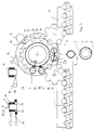
- Fig. 1 schematically shows a plan view of the device, in which certain parts have been omitted and parts of the bush have been shown separately on an enlarged scale, for the sake of clarity;
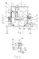
- Fig. 2 schematically shows a side view of parts of the device of figure 1, in particular for explaining their function;
- Fig. 3 schematically shows a vertical cross-section of a bush used with the device in which the outer wall of the bush has been extended; and
- Fig. 4 shows a part of the disc of the turret in which a container is supported by a platform being moveable in vertical direction.
-
- The device illustrated in the drawings comprises means for cutting a part, in the shape of a sleeve, from a flattened tube drawn from a supply roller. Such a means is known from EP-B-0 109 105 so that discussion thereof is considered to be superfluous.
- The cut-off sleeve 1 is inserted into a
bush 2, consisting of a perforatedinner wall 3 and anouter wall 4 connected to it, so that an interior, closed-offspace 5 is situated between bothwalls inner wall 3 can be provided with at least oneslot 6 facing outwards. In order to clarify this, the inner and outer walls have been illustrated separately in figure 1. - In order to insert the sleeve 1 at the appropriate position in the bush, a
stop member 7 is fixedly mounted there. Thestop member 7 is in the form of a substantially horizontally extendingrod 8 which, when the sleeve 1 is inserted into thebush 2, will be situated at some distance below the bush and will closely engage the bottom of the bush when the latter is moved substantially in horizontal direction. To that end, therod 8 can be sligthly bent, for example. The rod will be connected to a part of theframe 9 of the device in a way not further indicated. - The device comprises a turret which is formed by a
disc 10 consisting of a number of parts, said disc having a lowermostannular part 10a being provided with atoothing 11, so that the disc can be rotated by means of a motor-drivengear wheel 12. Theannular part 10a is provided with aninner edge 10b cooperating withrollers 10c, being rotatably mounted on theframe 9. - Next to the
disc 10, aconveyor belt 13 extends, by whichcontainers 14 can be supplied to the disc. By means of aworm shaft 15, thecontainers 14 are brought at the appropriate mutual distance. For bringing thecontainers 14 onto thedisc 10 and removing them from it, twostar wheels 16 are employed. The direction of rotation of thedisc 10 and of thestar wheels 16 is indicated by arrows. The rotation of theworm shaft 15 and of thestar wheels 16 is synchronized with the rotation of thedisc 10. - It will be obvious that only some of the
containers 14 present on thedisc 10 during operation of the device have been illustrated in the figures. - For each
container 14 on thedisc 10, there is abush 2, only some of which having been shown. Eachbush 2 is provided with a guidingmember 17 which is slidable along a vertically extendingguide 18 connected to thedisc 10. - As appears from figure 2 in particular, a
curve track 19 fixedly connected to theframe 9 of the device is used for vertical movement of thebushes 2. The curve track can be in the shape of a cylindrical plate, as seen in plan view, which however need not extend across the entire circumference of thedisc 10. The guidingmember 17 of abush 2 lies, possibly with intervention of a roller, against the theupper edge 20 of thecurve track 19. The guidingmember 17 of thebush 2 is pulled downwards against theupper edge 20 of thecurve track 19 by means of aspring 21. - The highest point of the
curve track 19, as illustrated in figure 2, will be situated near theconveyor belt 13 between thestar wheels 16, at the place where there is nocontainer 14 on thedisc 10. At that position, a sleeve 1 is inserted into abush 2. Insertion of a sleeve into thebush 2 happens so quickly that, in general, thedisc 10 need not be stopped. In theinternal space 5 of thebush 2 underpressure is now generated by means of avacuum line 22 connected to said space, said vacuum line extending to avacuum connecting plate 23 of which only a small part has been illustrated in figure 1. The connectingplate 23 moves along with thedisc 10 or is part of it. In a way not further indicated, an opening in the connecting plate will be in communication with a fixedly arrangedvacuum chamber 31 situated below it, during a portion of the revolution of the plate. Thus, during a certain portion of a revolution of thedisc 10 an underpressure will be generated in thespace 5. - After a sleeve 1 has been brought into the
bush 2 and is fixed in it by underpressure thebush 2, moving along with thedisc 10, slides downwards along thecurve track 19 across acontainer 14 under influence of its weight and thespring 21. When the bush has reached its lowermost position and thus the sleeve 1 is at its place onto thecontainer 14, the underpressure inspace 5 of thebush 2 will be released and the sleeve will be positioned on thecontainer 14. - For positively keeping the sleeve 1 on the
container 14, a blowingnozzle 24 can be used, by which hot air is blown onto the lower edge of the sleeve 1, so that the sleeve is shrunk around thecontainer 14. The blowing nozzle need not be on the place shown in figure 1. After that, thebush 2 can start moving upwards under the influence of thecurve track 19. It will be obvious, that thebush 2 can be in its lowermost position across a certain part of a revolution of thedisc 10, so that basically, thecurve track 19 can be omitted there. - It is important that on engaging the
disc 10, acontainer 14 is kept in the appropriate position, so that abush 2 slides across thecontainer 14 during its downwards movement and does not contact the container in such a way that it could be pushed over. To that end, thecontainer 14 can be held in that thedisc 10 has anopening 25 for each container, which opening is connected to avacuum chamber 26 extending across at least a part of the circumference of thedisc 10. It will be obvious, that figure 2 basically shows an inner circumference part of thedisc 10, in flattened shape, with thecurve track 19 and some further parts. - Now it is possible that the bottom of a
container 14 is not suitable for being pulled against thedisc 10 by underpressure. In that case,openings 27 can be provided in thedisc 10, around the location where a container will be situated. Through said openings pins 28 can be led upwards when acontainer 14 is situated at its place on thedisc 10. Thepins 28 can e.g. be provided on asupport member 29 being movable in vertical direction, by acurve track 30 fixedly mounted below the disc of the turret. - Fig. 3 shows the possibility of providing the
outer wall 4 of the bush with anextended portion 32 for forming achamber 33 to which hot air can be supplied by means of aline 34 in order to shrink a sleeve 1 when it has been brought around a container. - According to figure 4 a
container 14 is positioned on aplatform 35 being smaller than the bottom of the container and being vertically movable in respect of thedisc 10. To that end, theplatform 35 is mounted on apipe 36 being guided by thedisc 10 and having its lower end carrying aroller 37 moving across acurve track 38. Via thepipe 36 the bottom of thecontainer 14 is drawn against theplatform 35. The sleeve 1 can now extend up to some distance below the bottom of the container and will be shrunk onto the container below the bottom after applying of the sleeve. - It will be obvious, that only some possible embodiments of a device according to the invention have been illustrated in the drawing and explained in the description and that many changes can be made without leaving the inventive idea as it is described in the claims.
Claims (15)
- Device for fittinq a sleeve (1) on a container (14) such as a bottle or a similar object, said device comprising a double-walled bush (2) with its inner wall (3) perforated and the interior annular space (5) of the bush (2) being connectable to a vacuum line (22) for generating underpressure within the interior space (5) and sucking a sleeve (1) inserted in said bush against the wall so that a container can be brought into the sleeve whereupon the connection with the vacuum line is disconnected, characterized in that the device comprises a number of bushes (2), the inner and outer wall (3,4 resp.) of each bush being fixedly connected to each other and the axes of said bushes being directed vertically, positioning means (19,20) for the bushes (2) being present so that a sleeve (1), obtained by cutting-off a part of a flattened plastic tube drawn from a supply roller, can be slid into the bush in vertical direction and can be sucked against the inner wall (3) of it, whereupon the positioning means (19,20) can slide the bush (2) and the sleeve across a container (14) and the connection with the vacuum line (22) can be disconnected.
- Device according to claim 1, characterized in that a means (24;32-34) is present for blowing hot air onto the lower edge of the sleeve (1) when the bush (2) is in its lowermost position on the container (14).
- Device according to claim 2, characterized in that the outer wall (4) of the bush is provided with a downwards extending portion (32) such that a chamber (33) is obtained to which a line (34) for hot air can be connected.
- Device according to one of the preceding claims, characterized in that the inner wall (3) of the bush (2) is provided with at least one slot (6) facing outwards.
- Device according to one of the preceding claims, characterized in that a fixedly arranged stop member (7) for the sleeve (1) is situated below the bush (2), at the place where a sleeve (1) is inserted into it.
- Device according to claim 5, characterized in that the stop member (7) is in the form of a substantially horizontally extending rod (8) being situated at some distance from the bush (2) at the position where the sleeve is inserted into said bush, and which, on moving the bush (2) or the rod (8) substantially in horizontal direction, will closely engage the bottom side of the bush (2).
- Device according to one of the preceding claims, characterized in that the device comprises a turret in which a number of containers (14) can be brought onto a rotating disc (10) from which disc (10) they will be removed after a certain rotation of it, the number of bushes (2) being at least equal to the number of containers (14) which can be present on said disc (10) and the guiding member (17) of each bush (2) being slidable along a substantially vertically extending guide (18) connected to the disc (10).
- Device according to claim 7, characterized in that for vertical movement of the bushes (2), a curve track (19, 20) fixedly mounted in the device is used, against which the guide member (17) of the bush (2) is drawn downwards by means of a spring (21), in which the sleeve (1) is inserted into the bush (2) at almost the highest point of the track.
- Device according to claim 7 or 8, characterized in that the vacuum lines (22) of the bushes (2) situated on the turret are connected to an annular vacuum switching plate (23) extending around the rotary shaft of the disc (10) of the turret and moving along with it, or being part of it, an opening in the vacuum switching plate during part of its rotation communicating with a stationary arranged vacuum chamber (31) situated underneath the switching plate.
- Device according to one of the claims 7 - 9, characterized in that a means (26 - 30) is provided for holding containers (14) positioned on the disc (10) of the turret.
- Device according to claim 10, characterized in that the means for keeping a container in its place on the disc (10) of the turret is in the form of openings (25) in the disc (10) which can be connected to at least one vacuum chamber (26) situated below the disc (10).
- Device according to one of the claims 7 - 9, characterized in that the disc (10) of the turret is provided with platforms (35) being movable mounted in vertical direction in the disc of the turret and being provided with a connection (36) for a vacuum line, said platform supporting only the central part of the bottom of the container (14).
- Device according to claim 10, characterized in that the disc (10) has a number of openings (27) for each container (14), to wit at least three, through which pins (28) can be slid from below till beyond the surface of the disc (10), which will be situated around the container (14), with the pins (28) being mounted on a support member (29) being movable in vertical direction by operating means (30).
- Device according to claim 13, characterized in that the operating means for moving the pin-bearing (28) support member (29) up and down are in the form of a curve track (30) fixedly mounted below the disc (10) of the turret.
- Method for using the device according to one or more of the preceding claims, characterized in that a sleeve (1) is cut-off from a flattened tube drawn from a supply roller, the sleeve being slid vertically into a double-walled bush (2) having its inner wall (3) perforated, air being drawn from the space (5) around the inner wall so that the sleeve (1) is pressed against the inner wall (3), the bush (2) being slid across a container (14), the underpressure in the space (5) being removed, a stream of hot air being directed at the lower edge of the sleeve (1) and the bush being returned to its initial position.
Applications Claiming Priority (2)
| Application Number | Priority Date | Filing Date | Title |
|---|---|---|---|
| NL1015124A NL1015124C2 (en) | 2000-05-04 | 2000-05-04 | Device for applying a sleeve to a holder and method for applying the device. |
| NL1015124 | 2000-05-04 |
Publications (2)
| Publication Number | Publication Date |
|---|---|
| EP1151847A1 true EP1151847A1 (en) | 2001-11-07 |
| EP1151847B1 EP1151847B1 (en) | 2003-10-15 |
Family
ID=19771331
Family Applications (1)
| Application Number | Title | Priority Date | Filing Date |
|---|---|---|---|
| EP01201420A Expired - Lifetime EP1151847B1 (en) | 2000-05-04 | 2001-04-19 | Device for fitting a sleve on a container and method of applying the device |
Country Status (10)
| Country | Link |
|---|---|
| US (1) | US6755012B2 (en) |
| EP (1) | EP1151847B1 (en) |
| JP (1) | JP2002002610A (en) |
| AT (1) | ATE251985T1 (en) |
| DE (1) | DE60100963T2 (en) |
| DK (1) | DK1151847T3 (en) |
| ES (1) | ES2207592T3 (en) |
| NL (1) | NL1015124C2 (en) |
| PT (1) | PT1151847E (en) |
| TR (1) | TR200301911T4 (en) |
Cited By (2)
| Publication number | Priority date | Publication date | Assignee | Title |
|---|---|---|---|---|
| WO2012107812A1 (en) * | 2011-02-11 | 2012-08-16 | Sidel S.P.A. Con Socio Unico | Vacuum transfer element and method for transferring tubular labels |
| US9637264B2 (en) | 2010-01-28 | 2017-05-02 | Avery Dennison Corporation | Label applicator belt system |
Families Citing this family (7)
| Publication number | Priority date | Publication date | Assignee | Title |
|---|---|---|---|---|
| JP4332779B2 (en) * | 2003-06-10 | 2009-09-16 | 澁谷工業株式会社 | Tube fitting device for container exterior |
| WO2008076718A1 (en) * | 2006-12-15 | 2008-06-26 | Ccl Label Gmbh | Stretch film sleeve label applicator |
| US8973385B2 (en) * | 2007-03-02 | 2015-03-10 | Hill Phoenix, Inc. | Refrigeration system |
| US8282754B2 (en) | 2007-04-05 | 2012-10-09 | Avery Dennison Corporation | Pressure sensitive shrink label |
| CN106564668A (en) | 2007-04-05 | 2017-04-19 | 艾利丹尼森公司 | Pressure sensitive shrink label |
| US8171706B2 (en) * | 2009-11-01 | 2012-05-08 | Chin-Tzu Chiu | Wrapping machine |
| DE102011090102A1 (en) * | 2011-12-29 | 2013-07-04 | Krones Aktiengesellschaft | Apparatus and method for attaching shrink sleeves to containers |
Citations (7)
| Publication number | Priority date | Publication date | Assignee | Title |
|---|---|---|---|---|
| US3841940A (en) * | 1972-11-29 | 1974-10-15 | A Rubinichi | Apparatus for applying advertising bands on cylindrical containers |
| US3852940A (en) * | 1972-05-30 | 1974-12-10 | Ryohsei Plastic Ind Co Ltd | Automatic cap sealing device |
| US4286421A (en) * | 1979-01-18 | 1981-09-01 | Fuji Seal Industry Co., Ltd. | Method and machine for fitting a sleeve seal of a collapsed form over a container |
| EP0437022A1 (en) * | 1990-01-12 | 1991-07-17 | Shibuya America Corporation | Method of applying a plastic wrap to a contoured container |
| FR2669908A1 (en) * | 1990-11-30 | 1992-06-05 | Gangloff | Device for gripping a tubular sleeve in the flat state, for shaping it and for mounting it on a support |
| US5188775A (en) * | 1990-09-17 | 1993-02-23 | Owens-Illinois Plastic Products Inc. | Method and apparatus for shrinking a foam sleeve on a taper wall container |
| US5715651A (en) * | 1994-08-23 | 1998-02-10 | Protection Decoration Conditionment | Process and machine for fitting stretchable labelling sleeves on bottles or the like |
Family Cites Families (10)
| Publication number | Priority date | Publication date | Assignee | Title |
|---|---|---|---|---|
| US2976661A (en) * | 1957-08-16 | 1961-03-28 | Albro Fillers & Engineering Co | Devices for applying sealing bands to articles |
| US3888067A (en) * | 1973-09-18 | 1975-06-10 | Gilbreth Co | Banding machine |
| US3959065A (en) * | 1974-04-25 | 1976-05-25 | Owens-Illinois, Inc. | Method and apparatus for producing plastic-covered containers |
| JPS5833813B2 (en) * | 1977-12-19 | 1983-07-22 | 東洋ガラス株式会社 | Plastic sleeve manufacturing method and device |
| US4184309A (en) * | 1978-08-02 | 1980-01-22 | Owens-Illinois, Inc. | Method and apparatus for assemblying tubular sleeve preforms and containers |
| US4318685A (en) * | 1981-01-05 | 1982-03-09 | Konstantin Anatole E | Insert bander |
| NL8204315A (en) | 1982-11-08 | 1984-06-01 | Intermatic Machines B V | Device for spreading a tube of flexible material. |
| US4719739A (en) * | 1986-09-16 | 1988-01-19 | Montreal Milling Cutter Company, Inc. | Continuous motion in-line sealer |
| DE4206594A1 (en) * | 1992-03-03 | 1993-09-09 | Alfill Getraenketechnik | METHOD AND DEVICE FOR APPLYING AN ALL-ROUND LABEL ON A CONTAINER |
| US5566527A (en) * | 1995-05-23 | 1996-10-22 | H.G. Kalish, Inc. | Apparatus for applying a heat-shrinkable band to the neck of a container |
-
2000
- 2000-05-04 NL NL1015124A patent/NL1015124C2/en not_active IP Right Cessation
-
2001
- 2001-04-19 ES ES01201420T patent/ES2207592T3/en not_active Expired - Lifetime
- 2001-04-19 EP EP01201420A patent/EP1151847B1/en not_active Expired - Lifetime
- 2001-04-19 TR TR2003/01911T patent/TR200301911T4/en unknown
- 2001-04-19 PT PT01201420T patent/PT1151847E/en unknown
- 2001-04-19 DK DK01201420T patent/DK1151847T3/en active
- 2001-04-19 AT AT01201420T patent/ATE251985T1/en not_active IP Right Cessation
- 2001-04-19 DE DE60100963T patent/DE60100963T2/en not_active Expired - Lifetime
- 2001-05-02 JP JP2001135251A patent/JP2002002610A/en active Pending
- 2001-05-03 US US09/847,585 patent/US6755012B2/en not_active Expired - Fee Related
Patent Citations (7)
| Publication number | Priority date | Publication date | Assignee | Title |
|---|---|---|---|---|
| US3852940A (en) * | 1972-05-30 | 1974-12-10 | Ryohsei Plastic Ind Co Ltd | Automatic cap sealing device |
| US3841940A (en) * | 1972-11-29 | 1974-10-15 | A Rubinichi | Apparatus for applying advertising bands on cylindrical containers |
| US4286421A (en) * | 1979-01-18 | 1981-09-01 | Fuji Seal Industry Co., Ltd. | Method and machine for fitting a sleeve seal of a collapsed form over a container |
| EP0437022A1 (en) * | 1990-01-12 | 1991-07-17 | Shibuya America Corporation | Method of applying a plastic wrap to a contoured container |
| US5188775A (en) * | 1990-09-17 | 1993-02-23 | Owens-Illinois Plastic Products Inc. | Method and apparatus for shrinking a foam sleeve on a taper wall container |
| FR2669908A1 (en) * | 1990-11-30 | 1992-06-05 | Gangloff | Device for gripping a tubular sleeve in the flat state, for shaping it and for mounting it on a support |
| US5715651A (en) * | 1994-08-23 | 1998-02-10 | Protection Decoration Conditionment | Process and machine for fitting stretchable labelling sleeves on bottles or the like |
Cited By (6)
| Publication number | Priority date | Publication date | Assignee | Title |
|---|---|---|---|---|
| US9637264B2 (en) | 2010-01-28 | 2017-05-02 | Avery Dennison Corporation | Label applicator belt system |
| WO2012107812A1 (en) * | 2011-02-11 | 2012-08-16 | Sidel S.P.A. Con Socio Unico | Vacuum transfer element and method for transferring tubular labels |
| CN103442986A (en) * | 2011-02-11 | 2013-12-11 | 西得乐独资股份公司 | Vacuum transfer element and method for transferring tubular labels |
| JP2014508078A (en) * | 2011-02-11 | 2014-04-03 | シデル エッセ.ピ.ア. コン ソシオ ウニコ | Vacuum transfer element and method for cylindrical label transfer Multiple vacuum transfer element and method for cylindrical label transfer |
| CN103442986B (en) * | 2011-02-11 | 2015-12-09 | 西得乐独资股份公司 | For carrying vacuum handling part and the method for tubular labels |
| US9296507B2 (en) | 2011-02-11 | 2016-03-29 | Sidel S.P.A. Con Socio Unico | Vacuum transfer element and method for transferring tubular labels |
Also Published As
| Publication number | Publication date |
|---|---|
| DE60100963D1 (en) | 2003-11-20 |
| ES2207592T3 (en) | 2004-06-01 |
| US6755012B2 (en) | 2004-06-29 |
| DK1151847T3 (en) | 2003-12-22 |
| DE60100963T2 (en) | 2004-07-22 |
| PT1151847E (en) | 2004-03-31 |
| TR200301911T4 (en) | 2004-01-21 |
| EP1151847B1 (en) | 2003-10-15 |
| US20020017083A1 (en) | 2002-02-14 |
| NL1015124C2 (en) | 2001-11-06 |
| ATE251985T1 (en) | 2003-11-15 |
| JP2002002610A (en) | 2002-01-09 |
Similar Documents
| Publication | Publication Date | Title |
|---|---|---|
| US7870882B2 (en) | Process and apparatus for forming tubular labels of heat shrinkable film and inserting containers therein | |
| US4104845A (en) | Method and apparatus for applying sleeves to necks of bottles and other containers | |
| US4208857A (en) | Sleeve seal fitting machine | |
| US5483783A (en) | High speed sleever | |
| EP1151847B1 (en) | Device for fitting a sleve on a container and method of applying the device | |
| JP3574212B2 (en) | Apparatus for unfolding flattened cylindrical blanks into corresponding containers | |
| US3293823A (en) | Capping apparatus | |
| JP6050256B2 (en) | Vacuum transfer element and method for cylindrical label transfer Multiple vacuum transfer element and method for cylindrical label transfer | |
| JP4744730B2 (en) | Device for attaching labels and sleeves to containers | |
| CA2082316A1 (en) | High speed sleever | |
| US5419095A (en) | Bag stripping apparatus | |
| KR101013393B1 (en) | Apparatus for fitting a wrapping tube on a vessel | |
| EP0320376B1 (en) | Arrangement for applying tubular labels to objects such as cans | |
| FR2508841A1 (en) | METHOD AND APPARATUS FOR INSTALLING AND CENTERING THERMORETRACTABLE SHEATH AROUND OBJECTS USING A VERTICAL FLOATING CHUCK ASSEMBLY | |
| EP3529409B1 (en) | Device and method for placing and extracting socks from sock forms | |
| JP4777532B2 (en) | Label mounting device | |
| MX2007010502A (en) | Unit and method for compression moulding polymeric articles. | |
| FR3058404A1 (en) | SYSTEM FOR CONVEYING THERMOPLASTIC OBJECTS HAVING A HOLLOW BODY WITH A COLLAR | |
| CA1084016A (en) | Method and apparatus for applying sleeves to necks of bottles and other containers | |
| EP0778206A2 (en) | Automatic device for gripping and holding flexible bag-shaped containers and by means of independent gripping units | |
| JP2002284130A (en) | Label sticking equipment | |
| FR2489797A1 (en) | ASSEMBLER FOR THE MAKING OF WORKS SUCH AS BUNDLES, FORMS OR THE LIKE | |
| KR0175209B1 (en) | Process and machine for fitting stretchable labelling sleeves or bottles or the like | |
| JP5778289B2 (en) | Label mounting device | |
| JP3581197B2 (en) | Label removal device |
Legal Events
| Date | Code | Title | Description |
|---|---|---|---|
| PUAI | Public reference made under article 153(3) epc to a published international application that has entered the european phase |
Free format text: ORIGINAL CODE: 0009012 |
|
| AK | Designated contracting states |
Kind code of ref document: A1 Designated state(s): AT BE CH CY DE DK ES FI FR GB GR IE IT LI LU MC NL PT SE TR |
|
| AX | Request for extension of the european patent |
Free format text: AL;LT;LV;MK;RO;SI |
|
| 17P | Request for examination filed |
Effective date: 20020122 |
|
| AKX | Designation fees paid |
Free format text: AT BE CH CY DE DK ES FI FR GB GR IE IT LI LU MC NL PT SE TR |
|
| GRAH | Despatch of communication of intention to grant a patent |
Free format text: ORIGINAL CODE: EPIDOS IGRA |
|
| GRAS | Grant fee paid |
Free format text: ORIGINAL CODE: EPIDOSNIGR3 |
|
| GRAA | (expected) grant |
Free format text: ORIGINAL CODE: 0009210 |
|
| AK | Designated contracting states |
Kind code of ref document: B1 Designated state(s): AT BE CH CY DE DK ES FI FR GB GR IE IT LI LU MC NL PT SE TR |
|
| REG | Reference to a national code |
Ref country code: CH Ref legal event code: EP Ref country code: GB Ref legal event code: FG4D |
|
| REG | Reference to a national code |
Ref country code: IE Ref legal event code: FG4D |
|
| REF | Corresponds to: |
Ref document number: 60100963 Country of ref document: DE Date of ref document: 20031120 Kind code of ref document: P |
|
| REG | Reference to a national code |
Ref country code: CH Ref legal event code: NV Representative=s name: ISLER & PEDRAZZINI AG |
|
| REG | Reference to a national code |
Ref country code: GR Ref legal event code: EP Ref document number: 20030404596 Country of ref document: GR Ref country code: DK Ref legal event code: T3 |
|
| REG | Reference to a national code |
Ref country code: SE Ref legal event code: TRGR |
|
| REG | Reference to a national code |
Ref country code: PT Ref legal event code: SC4A Free format text: AVAILABILITY OF NATIONAL TRANSLATION Effective date: 20040113 |
|
| REG | Reference to a national code |
Ref country code: ES Ref legal event code: FG2A Ref document number: 2207592 Country of ref document: ES Kind code of ref document: T3 |
|
| ET | Fr: translation filed | ||
| PLBE | No opposition filed within time limit |
Free format text: ORIGINAL CODE: 0009261 |
|
| STAA | Information on the status of an ep patent application or granted ep patent |
Free format text: STATUS: NO OPPOSITION FILED WITHIN TIME LIMIT |
|
| 26N | No opposition filed |
Effective date: 20040716 |
|
| PGFP | Annual fee paid to national office [announced via postgrant information from national office to epo] |
Ref country code: CY Payment date: 20060125 Year of fee payment: 6 |
|
| PGFP | Annual fee paid to national office [announced via postgrant information from national office to epo] |
Ref country code: MC Payment date: 20060228 Year of fee payment: 6 |
|
| PGFP | Annual fee paid to national office [announced via postgrant information from national office to epo] |
Ref country code: TR Payment date: 20060404 Year of fee payment: 6 |
|
| PGFP | Annual fee paid to national office [announced via postgrant information from national office to epo] |
Ref country code: LU Payment date: 20060414 Year of fee payment: 6 |
|
| PGFP | Annual fee paid to national office [announced via postgrant information from national office to epo] |
Ref country code: PT Payment date: 20070226 Year of fee payment: 7 |
|
| PGFP | Annual fee paid to national office [announced via postgrant information from national office to epo] |
Ref country code: FI Payment date: 20070329 Year of fee payment: 7 |
|
| PGFP | Annual fee paid to national office [announced via postgrant information from national office to epo] |
Ref country code: DK Payment date: 20070410 Year of fee payment: 7 |
|
| REG | Reference to a national code |
Ref country code: CH Ref legal event code: PCAR Free format text: ISLER & PEDRAZZINI AG;POSTFACH 1772;8027 ZUERICH (CH) |
|
| PG25 | Lapsed in a contracting state [announced via postgrant information from national office to epo] |
Ref country code: MC Free format text: LAPSE BECAUSE OF NON-PAYMENT OF DUE FEES Effective date: 20070430 |
|
| PG25 | Lapsed in a contracting state [announced via postgrant information from national office to epo] |
Ref country code: CY Free format text: LAPSE BECAUSE OF NON-PAYMENT OF DUE FEES Effective date: 20070419 |
|
| PGFP | Annual fee paid to national office [announced via postgrant information from national office to epo] |
Ref country code: GR Payment date: 20070430 Year of fee payment: 7 Ref country code: IE Payment date: 20080211 Year of fee payment: 8 |
|
| PGFP | Annual fee paid to national office [announced via postgrant information from national office to epo] |
Ref country code: CH Payment date: 20080430 Year of fee payment: 8 |
|
| PGFP | Annual fee paid to national office [announced via postgrant information from national office to epo] |
Ref country code: AT Payment date: 20080327 Year of fee payment: 8 Ref country code: BE Payment date: 20080207 Year of fee payment: 8 |
|
| PGFP | Annual fee paid to national office [announced via postgrant information from national office to epo] |
Ref country code: NL Payment date: 20080429 Year of fee payment: 8 Ref country code: SE Payment date: 20080416 Year of fee payment: 8 |
|
| REG | Reference to a national code |
Ref country code: PT Ref legal event code: MM4A Free format text: LAPSE DUE TO NON-PAYMENT OF FEES Effective date: 20081020 |
|
| REG | Reference to a national code |
Ref country code: DK Ref legal event code: EBP |
|
| PG25 | Lapsed in a contracting state [announced via postgrant information from national office to epo] |
Ref country code: PT Free format text: LAPSE BECAUSE OF NON-PAYMENT OF DUE FEES Effective date: 20081020 |
|
| PG25 | Lapsed in a contracting state [announced via postgrant information from national office to epo] |
Ref country code: FI Free format text: LAPSE BECAUSE OF NON-PAYMENT OF DUE FEES Effective date: 20080419 |
|
| PG25 | Lapsed in a contracting state [announced via postgrant information from national office to epo] |
Ref country code: DK Free format text: LAPSE BECAUSE OF NON-PAYMENT OF DUE FEES Effective date: 20080430 |
|
| PG25 | Lapsed in a contracting state [announced via postgrant information from national office to epo] |
Ref country code: GR Free format text: LAPSE BECAUSE OF NON-PAYMENT OF DUE FEES Effective date: 20081104 |
|
| PG25 | Lapsed in a contracting state [announced via postgrant information from national office to epo] |
Ref country code: LU Free format text: LAPSE BECAUSE OF NON-PAYMENT OF DUE FEES Effective date: 20070419 |
|
| PG25 | Lapsed in a contracting state [announced via postgrant information from national office to epo] |
Ref country code: TR Free format text: LAPSE BECAUSE OF FAILURE TO SUBMIT A TRANSLATION OF THE DESCRIPTION OR TO PAY THE FEE WITHIN THE PRESCRIBED TIME-LIMIT Effective date: 20031015 |
|
| BERE | Be: lapsed |
Owner name: *FUJI SEAL EUROPE B.V. Effective date: 20090430 |
|
| REG | Reference to a national code |
Ref country code: CH Ref legal event code: PL |
|
| EUG | Se: european patent has lapsed | ||
| NLV4 | Nl: lapsed or anulled due to non-payment of the annual fee |
Effective date: 20091101 |
|
| PG25 | Lapsed in a contracting state [announced via postgrant information from national office to epo] |
Ref country code: AT Free format text: LAPSE BECAUSE OF NON-PAYMENT OF DUE FEES Effective date: 20090419 Ref country code: LI Free format text: LAPSE BECAUSE OF NON-PAYMENT OF DUE FEES Effective date: 20090430 Ref country code: CH Free format text: LAPSE BECAUSE OF NON-PAYMENT OF DUE FEES Effective date: 20090430 |
|
| REG | Reference to a national code |
Ref country code: IE Ref legal event code: MM4A |
|
| PG25 | Lapsed in a contracting state [announced via postgrant information from national office to epo] |
Ref country code: NL Free format text: LAPSE BECAUSE OF NON-PAYMENT OF DUE FEES Effective date: 20091101 |
|
| PG25 | Lapsed in a contracting state [announced via postgrant information from national office to epo] |
Ref country code: IE Free format text: LAPSE BECAUSE OF NON-PAYMENT OF DUE FEES Effective date: 20090420 |
|
| PG25 | Lapsed in a contracting state [announced via postgrant information from national office to epo] |
Ref country code: BE Free format text: LAPSE BECAUSE OF NON-PAYMENT OF DUE FEES Effective date: 20090430 |
|
| PGFP | Annual fee paid to national office [announced via postgrant information from national office to epo] |
Ref country code: ES Payment date: 20100409 Year of fee payment: 10 |
|
| PGFP | Annual fee paid to national office [announced via postgrant information from national office to epo] |
Ref country code: IT Payment date: 20100408 Year of fee payment: 10 |
|
| PGFP | Annual fee paid to national office [announced via postgrant information from national office to epo] |
Ref country code: GB Payment date: 20100426 Year of fee payment: 10 |
|
| PG25 | Lapsed in a contracting state [announced via postgrant information from national office to epo] |
Ref country code: SE Free format text: LAPSE BECAUSE OF NON-PAYMENT OF DUE FEES Effective date: 20090420 |
|
| PGFP | Annual fee paid to national office [announced via postgrant information from national office to epo] |
Ref country code: FR Payment date: 20110420 Year of fee payment: 11 |
|
| GBPC | Gb: european patent ceased through non-payment of renewal fee |
Effective date: 20110419 |
|
| PG25 | Lapsed in a contracting state [announced via postgrant information from national office to epo] |
Ref country code: IT Free format text: LAPSE BECAUSE OF NON-PAYMENT OF DUE FEES Effective date: 20110419 Ref country code: GB Free format text: LAPSE BECAUSE OF NON-PAYMENT OF DUE FEES Effective date: 20110419 |
|
| REG | Reference to a national code |
Ref country code: ES Ref legal event code: FD2A Effective date: 20120524 |
|
| PG25 | Lapsed in a contracting state [announced via postgrant information from national office to epo] |
Ref country code: ES Free format text: LAPSE BECAUSE OF NON-PAYMENT OF DUE FEES Effective date: 20110420 |
|
| REG | Reference to a national code |
Ref country code: FR Ref legal event code: ST Effective date: 20121228 |
|
| PG25 | Lapsed in a contracting state [announced via postgrant information from national office to epo] |
Ref country code: FR Free format text: LAPSE BECAUSE OF NON-PAYMENT OF DUE FEES Effective date: 20120430 |
|
| PGFP | Annual fee paid to national office [announced via postgrant information from national office to epo] |
Ref country code: DE Payment date: 20130430 Year of fee payment: 13 |
|
| REG | Reference to a national code |
Ref country code: DE Ref legal event code: R119 Ref document number: 60100963 Country of ref document: DE |
|
| PG25 | Lapsed in a contracting state [announced via postgrant information from national office to epo] |
Ref country code: DE Free format text: LAPSE BECAUSE OF NON-PAYMENT OF DUE FEES Effective date: 20141101 |
|
| REG | Reference to a national code |
Ref country code: DE Ref legal event code: R119 Ref document number: 60100963 Country of ref document: DE Effective date: 20141101 |