EP1154151A1 - Injection valve with single disc turbulence generation - Google Patents
Injection valve with single disc turbulence generation Download PDFInfo
- Publication number
- EP1154151A1 EP1154151A1 EP01201450A EP01201450A EP1154151A1 EP 1154151 A1 EP1154151 A1 EP 1154151A1 EP 01201450 A EP01201450 A EP 01201450A EP 01201450 A EP01201450 A EP 01201450A EP 1154151 A1 EP1154151 A1 EP 1154151A1
- Authority
- EP
- European Patent Office
- Prior art keywords
- needle
- metering
- fuel
- orifice
- fuel injector
- Prior art date
- Legal status (The legal status is an assumption and is not a legal conclusion. Google has not performed a legal analysis and makes no representation as to the accuracy of the status listed.)
- Granted
Links
- 238000002347 injection Methods 0.000 title description 3
- 239000007924 injection Substances 0.000 title description 3
- 239000000446 fuel Substances 0.000 claims abstract description 108
- 238000007789 sealing Methods 0.000 claims abstract description 18
- 238000000034 method Methods 0.000 claims abstract description 6
- 238000011144 upstream manufacturing Methods 0.000 claims description 6
- 238000002485 combustion reaction Methods 0.000 abstract description 15
- 239000000463 material Substances 0.000 description 2
- 239000002245 particle Substances 0.000 description 2
- 239000012080 ambient air Substances 0.000 description 1
- 238000000889 atomisation Methods 0.000 description 1
- 230000009286 beneficial effect Effects 0.000 description 1
- 230000003247 decreasing effect Effects 0.000 description 1
- 230000032798 delamination Effects 0.000 description 1
- 239000003989 dielectric material Substances 0.000 description 1
- 239000012530 fluid Substances 0.000 description 1
- 239000000203 mixture Substances 0.000 description 1
- 238000012986 modification Methods 0.000 description 1
- 230000004048 modification Effects 0.000 description 1
- 239000007800 oxidant agent Substances 0.000 description 1
- 239000007787 solid Substances 0.000 description 1
- 239000007921 spray Substances 0.000 description 1
- 229910001220 stainless steel Inorganic materials 0.000 description 1
- 239000010935 stainless steel Substances 0.000 description 1
Images

Classifications
-
- F—MECHANICAL ENGINEERING; LIGHTING; HEATING; WEAPONS; BLASTING
- F02—COMBUSTION ENGINES; HOT-GAS OR COMBUSTION-PRODUCT ENGINE PLANTS
- F02M—SUPPLYING COMBUSTION ENGINES IN GENERAL WITH COMBUSTIBLE MIXTURES OR CONSTITUENTS THEREOF
- F02M61/00—Fuel-injectors not provided for in groups F02M39/00 - F02M57/00 or F02M67/00
- F02M61/16—Details not provided for in, or of interest apart from, the apparatus of groups F02M61/02 - F02M61/14
- F02M61/18—Injection nozzles, e.g. having valve seats; Details of valve member seated ends, not otherwise provided for
- F02M61/1853—Orifice plates
Definitions
- This invention relates to fuel injectors, and more particularly, to fuel injectors having a single disc which generates turbulence at the metering orifices.
- Fuel injectors are commonly employed in internal combustion engines to provide precise metering of fuel for introduction into each combustion chamber. Additionally, the fuel injector atomizes the fuel during injection, breaking the fuel into a large number of very small particles, increasing the surface area of the fuel being injected and allowing the oxidizer, typically ambient air, to more thoroughly mix with the fuel prior to combustion. The precise metering and atomization of the fuel reduces combustion emissions and increases the fuel efficiency of the engine.
- An electro-magnetic fuel injector typically utilizes a solenoid assembly to supply an actuating force to a fuel metering valve.
- the fuel metering valve is a plunger style needle valve which reciprocates between a closed position, when the needle is seated in a valve seat along a sealing diameter to prevent fuel from escaping through a metering orifice disc into the combustion chamber, and an open position, where the needle is lifted from the valve seat, allowing fuel to discharge through the metering orifice for introduction into the combustion chamber.
- the metering orifice disc includes a plurality of metering orifice openings which are directly below the needle and inward of the sealing diameter.
- This approach relies on a precise control of the distance between the end of the needle and the upstream surface of the metering orifice disc. Variations in needle geometry, sealing diameter, and lift of the needle can cause this critical dimension to change.
- Another approach to maintaining precise control of this dimension uses a multi-disc concept. However, this approach has the added complexity of orientation, delamination, and part handling.
- the present invention is a fuel injector comprising a housing, a valve seat, a metering orifice and a needle.
- the housing has an inlet, an outlet and a longitudinal axis extending therethrough.
- the valve seat is disposed proximate the outlet.
- the valve seat includes a passage having a sealing surface and an orifice.
- the metering orifice is located at the outlet and includes a plurality of metering openings extending therethrough.
- the needle is reciprocally located within the housing along the longitudinal axis between a first position wherein the needle is displaced from the valve seat, allowing fuel flow past the needle, and a second position wherein the needle is biased against the valve seat, precluding fuel flow past the needle.
- a controlled velocity channel is formed between the valve seat and the metering orifice. The controlled velocity channel extends outwardly from the orifice to the plurality of metering openings.
- the present invention is a method of generating turbulence in a fuel flow through a fuel injector.
- the method includes providing a fuel flow under pressure to the fuel injector.
- a valve in the fuel injector is opened and the pressurized fuel flows past the valve and into a fuel chamber.
- the fuel flow is directed at an initial velocity from the fuel chamber into a controlled velocity channel formed by a valve seat and a metering orifice.
- the controlled velocity channel tapers from a first height at an upstream end of the controlled velocity channel to a second height at a downstream end of the controlled velocity channel.
- the second height is smaller than the first height.
- the fuel maintains a generally controlled velocity through the controlled velocity channel.
- the final velocity is higher than the initial velocity and generates turbulence within the fuel flow.
- the fuel flow is then directed through at least one orifice opening downstream of the controlled velocity channel and out of the fuel injector.
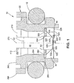
- a first preferred embodiment shown in Figs.1 and 2 is a fuel injector 10 for use in a fuel injection system of an internal combustion engine.
- the injector 10 includes a housing 20, a valve seat 30, a needle 40, and a generally planar fuel metering orifice 50. Details of the operation of the fuel injector 10 in relation to the operation of the internal combustion engine (not shown) are well known and will not be described in detail herein, except as the operation relates to the preferred embodiments.
- the preferred embodiments are generally directed to injectors for internal combustion engines, those skilled in the art will recognize from present disclosure that the preferred embodiments can be adapted for other applications in which precise metering of fluids is desired or required.
- the valve housing 20 has an upstream or inlet end 210 and a downstream or outlet end 220.
- the housing 20 further includes a valve body 260, which includes a housing chamber 262.
- the words "upstream” and “downstream” designate flow directions in the drawings to which reference is made.
- the upstream side is toward the top of each drawing and the downstream side is toward the bottom of each drawing.
- the housing chamber 262 extends through a central longitudinal portion of the valve housing 20 along a longitudinal axis 270 extending therethrough and is formed by an interior housing wall 264.
- a needle guide 280 having a central needle guide opening 284 and a plurality of radially spaced fuel flow openings 282 is located within the housing chamber 262 proximate to the downstream end 220 of the housing 20.
- the needle guide assists in maintaining reciprocation of the needle 40 along the longitudinal axis 270.
- An overmold 290 constructed of a dielectric material, preferably a plastic or other suitable material, encompasses the valve body 260.
- An o-ring 12 is located around the outer circumference of the valve body 260 to seat the injector 10 in the internal combustion engine (not shown).
- the valve seat 30 is located within the housing chamber 262 proximate to the outlet end 220 between the needle guide 280 and the discharge ends 220.
- the valve seat 30 includes a passage orifice 320 which extends generally along the longitudinal axis 270 of the housing 20 and is formed by a generally cylindrical wall 322. Preferably, a center 321 of the orifice 320 is on the longitudinal axis 270.
- the valve seat 30 also includes a beveled sealing surface 330 which surrounds the orifice 320 and tapers radially downward and inward toward the orifice 320 such that the sealing surface 330 is oblique to the longitudinal axis 270.
- the words "inward” and “outward” refer to directions towards and away from, respectively, the longitudinal axis 270.
- the needle 40 is reciprocally located within the housing chamber 262 generally along the longitudinal axis 270 of the housing 20.
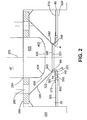
- the needle 40 is reciprocable between a first, or open, position wherein the needle 40 is displaced from the valve seat 30 (as shown in Fig.2), allowing pressurized fuel to flow downstream past the needle 40, and a second, or closed, position wherein the needle 40 is biased against the valve seat 30 (as shown in Fig.1) by a biasing element (not shown), preferably a spring, precluding fuel flow past the needle 40.
- the needle 40 includes a first portion 410 which has a first cross-sectional area A1 and a second portion 420 which has a second cross-sectional area A2.
- the second portion 420 includes a generally spherical valve contact face 422 which is sized to sealingly engage the beveled valve sealing surface 330 when the needle 40 is in the closed position.
- the spherical valve contact face 422 engages the beveled valve sealing surface 330 to provide a generally line contact therebetween.
- the line contact provides a solid seal between the needle 40 and the valve seat 30 and reduces the possibility of fuel leakage past the needle 40.
- the contact face 422, shown in enlarged Fig.2, connects with a planar end face 426 located at a downstream tip of the needle 40.
- the end face 426 is preferably generally perpendicular to the longitudinal axis 270 of the housing 20.
- both the first and second cross-sectional areas A1, A2 are circular, although those skilled in the art will recognize that the first and second cross-sectional areas A1, A2 can be other shapes as well.
- This configuration reduces the mass of the needle 40 while retaining a relatively large sealing diameter of the valve contact face 422 so as to provide a relatively generous sealing area of the needle 40 for engagement of the valve contact face 422 when the needle 40 is in the closed position.
- the increased cross-sectional area A2 of the needle also provides a larger guide surface relative to the mean needle diameter, thereby improving the wear resistance of the internal surface of the central needle guide opening 284.
- the improved wear resistance of the internal surface of the central needle guide opening 284 is due to reduced loading compared to that of a conventional base valve guide diameter which was used with prior art needles of a generally constant cross-sectional area.
- a typical prior art needle will have a substantially continuous cylindrically shaped shaft which terminates at an end portion wherein the cross-sectional area at the upper portion of the needle may be twice as much as the cross-sectional area A2 of the needle 40 shown in Fig.2.
- the needle 40 is reciprocable between the closed position (shown in Fig.1) and the open position (shown in Fig.2).
- a generally annular channel 430 is formed between the valve contact face 422 and the valve sealing surface 330.
- the metering orifice 50 is located within the housing chamber 262 and is connected to the housing 20, downstream of the valve seat 30.
- the metering orifice 50 has an interior face 510 facing the valve seat 30 and the needle 40, and an exterior face 520 facing the combustion chamber (not shown).
- a plane of the metering orifice 50 is generally parallel to the plane of the planar end face 426.
- a virtual extension 340 of the valve seat 30 can be projected onto the metering orifice 50 so as to intercept the interior face 510 of the metering orifice 50 at a point "A" shown in Fig.2.
- the metering orifice 50 preferably includes between four and twelve generally circular metering openings 530, although those skilled in the art will recognize that the metering orifice 50 can include less than four or more than twelve metering openings 530, and that the metering openings 530 can be other shapes, such as oval or any other suitable shape.
- a distance between adjacent metering openings 530 is at least approximately two and a half times as great as a diameter of the metering openings 530, although those skilled in the art will recognize that the distance between adjacent metering openings 530 can be less than that amount.
- the metering orifice 50 includes a raised portion 540 located within a perimeter determined by the metering openings 530.
- the raised portion 540 of the metering orifice 50 and the end face 426 are spaced from each other by between 50 microns and 250 microns, and, more preferably, by between 50 and 100 microns, although those skilled in the art will recognize that the distance can be less than 50 microns or greater than 100 microns.
- the raised portion 540 is preferably circular and reduces the sac volume 60 between the metering orifice 50 and the planar end face 426 of the needle 40. However, those skilled in the art will recognize that the raised portion 540 can be other shapes, such as oval.
- a continuous annular gap 542 is formed between the raised portion 540 and the orifice opening 330 in the valve seat 30. The gap 542 allows fuel flow between the metering orifice 50 and the valve seat 30 when the needle 40 is in the open position.
- valve seat 30 Downstream of the circular wall 322, the valve seat 30 tapers along a tapered portion 350 downward and outward in an oblique manner away from the orifice 320 to a point radially past the metering openings 530, where the valve seat 30 flattens to a bottom surface 550 preferably perpendicular to the longitudinal axis 270.
- the valve seat orifice 320 is preferably located wholly within the perimeter determined by the metering openings 530.
- the interior face 510 of the metering orifice 50 proximate to the outer perimeter of the metering orifice 50 engages the bottom surface 550 along a generally annular contact area.
- a generally annular controlled velocity channel 560 is formed between the tapered portion 350 of the valve seat 30 and interior face 510 of the metering orifice 50.
- the controlled velocity channel 560 provides a generally constant velocity, although those skilled in the art will recognize that the controlled velocity can vary throughout the length of the channel 560.
- the channel 560 tapers outwardly from a larger height A3 at the orifice 320 to a smaller height A4 toward the metering openings 530.
- a generally annular space 570 is formed between the interior face 510 of the metering orifice 50 radially outward of the metering openings 530 and the tapered portion 350 of the valve seat 30.
- pressurized fuel is provided to the injector 10 by a fuel pump (not shown).
- the pressurized fuel enters the injector 10 and passes through a fuel filter (not shown) to the housing chamber 262.
- the fuel flows through the housing chamber 262, the fuel flow openings 284 in the guide 280 to the interface between the valve contact face 422 and the valve sealing surface 330.
- the needle 40 is biased against the valve seat 30 so that the valve contact face 422 sealingly engages the valve sealing surface 330, preventing flow of fuel through the metering orifice 50.
- a solenoid or other actuating device reciprocates the needle 40 to an open position, removing the spherical contact face 422 of the needle 40 from the sealing surface 330 of the valve seat 30 and forming the generally annular channel 430.
- Pressurized fuel within the housing chamber 262 flows past the generally annular channel 430 formed by the needle 40 and the valve seat 30 and impinges on the raised portion 540 of the metering orifice 50.
- the fuel then flows generally radially outward along the raised portion 540 of the metering orifice 50 from the longitudinal axis 270, where the flow is redirected generally downward between the raised portion 540 and the valve seat orifice walls 322.
- the fuel is then directed generally radially outward from the longitudinal axis 270 through the generally annular channel 560 between the tapered portion 350 of the valve seat 30 and the metering orifice 50.
- the fuel attains a generally high velocity at the beginning of the generally annular channel 560.
- the perimeter of the fuel flow increases in a direct linear relationship to the distance from the longitudinal axis 270.
- the generally annular channel 560 can be used to accelerate or decelerate the velocity of the fuel if desired.
- the solenoid or other actuating device disengages, allowing the spring (not shown) to bias the needle 40 to the closed position, closing the generally annular channel 430 and seating the valve contact face 422 of the needle 40 onto the sealing surface 330 of the valve seat 30.
- valve seat 130 includes a valve sealing surface 132 and a valve orifice 134.
- the valve seat 130 is generally the same shape as the valve seat 30, with a tapered portion 136 which extends downward and outward in an oblique manner from the longitudinal axis 270 downstream from the valve orifice 134.
- the tapered portion 134 terminates at a location radially outward of the metering orifice openings 152.
- a generally annular controlled velocity channel 154 is formed between the metering orifice 150 radially outward of the metering openings 152 and the tapered portion 136 of the valve seat 130.
- the needle 140 differs from the needle 40 in the first embodiment in that the needle tip 142 does not include a flat end face.
- the needles 40, 140 can have a spherical, conical, tapered, flat, or other, suitable tip.
- the needle tip 142 engages the valve seat 130 in a generally circular point contact.
- a generally annular channel 144 is formed between the needle 140 and the valve seat 130.
- the metering orifice 150 shown in a top plan view in Fig.5, is generally planar and extends in a plane generally perpendicular to the longitudinal axis 270.
- the metering orifice 150 differs from the metering orifice 50 in that the metering orifice 150 does not include a raised portion 540.
- pressurized fuel flows through the channel 144 formed between the needle 140 and the valve seat 130.
- the fuel is directed into the valve seat orifice 134 and to the metering orifice 150.
- the fuel then is directed outward from the longitudinal axis 270 into the controlled velocity channel 154 where the fuel attains a high velocity at the entrance of the controlled velocity channel 154.
- the high fuel velocity directs the fuel across the metering orifice 150 and the orifice openings 152 in a transverse direction to the orifice openings 152, generating turbulence within the fuel which atomizes the fuel as the fuel travels through the orifice openings 152.
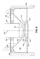
- the third embodiment shown in Fig.6, is similar to the second embodiment with the exception that, in the third embodiment, a metering orifice 600 between orifice openings 610 is generally rounded such that a concave surface 620 faces the needle 140.
- the valve seat 700 instead of tapering downward and outward in an oblique manner away from the longitudinal axis 270 below a valve seat orifice 710 along a bottom portion 720, preferably extends away from the longitudinal axis 270 generally perpendicular to the longitudinal axis 270.
- a generally annular channel 630 is formed between the bottom portion 720 of the valve seat 700 and the metering orifice 600.
- the channel 630 tapers outwardly from a larger height to a smaller height toward the orifice openings 610.
- a generally annular space 640 is formed between the metering orifice 600 radially outward of the metering openings 610 and the bottom portion 720 of the valve seat 700.
- the operation of the third embodiment is similar to the operation of the second embodiment described above.
- valve seat 30, the needle 40, and the metering orifice 50 are each constructed from stainless steel.
- valve seat 30, the needle 40 and the metering orifice 50 can be constructed of other, suitable materials.
Abstract
Description
- This invention relates to fuel injectors, and more particularly, to fuel injectors having a single disc which generates turbulence at the metering orifices.
- Fuel injectors are commonly employed in internal combustion engines to provide precise metering of fuel for introduction into each combustion chamber. Additionally, the fuel injector atomizes the fuel during injection, breaking the fuel into a large number of very small particles, increasing the surface area of the fuel being injected and allowing the oxidizer, typically ambient air, to more thoroughly mix with the fuel prior to combustion. The precise metering and atomization of the fuel reduces combustion emissions and increases the fuel efficiency of the engine.
- An electro-magnetic fuel injector typically utilizes a solenoid assembly to supply an actuating force to a fuel metering valve. Typically, the fuel metering valve is a plunger style needle valve which reciprocates between a closed position, when the needle is seated in a valve seat along a sealing diameter to prevent fuel from escaping through a metering orifice disc into the combustion chamber, and an open position, where the needle is lifted from the valve seat, allowing fuel to discharge through the metering orifice for introduction into the combustion chamber.
- Typically, the metering orifice disc includes a plurality of metering orifice openings which are directly below the needle and inward of the sealing diameter. This approach relies on a precise control of the distance between the end of the needle and the upstream surface of the metering orifice disc. Variations in needle geometry, sealing diameter, and lift of the needle can cause this critical dimension to change. Another approach to maintaining precise control of this dimension uses a multi-disc concept. However, this approach has the added complexity of orientation, delamination, and part handling.
- It would be beneficial to develop a fuel injector in which a controlled precise geometry is created at the downstream surface of the valve seat to generate desired turbulence at the metering orifice openings.
- Briefly, the present invention is a fuel injector comprising a housing, a valve seat, a metering orifice and a needle. The housing has an inlet, an outlet and a longitudinal axis extending therethrough. The valve seat is disposed proximate the outlet. The valve seat includes a passage having a sealing surface and an orifice. The metering orifice is located at the outlet and includes a plurality of metering openings extending therethrough. The needle is reciprocally located within the housing along the longitudinal axis between a first position wherein the needle is displaced from the valve seat, allowing fuel flow past the needle, and a second position wherein the needle is biased against the valve seat, precluding fuel flow past the needle. A controlled velocity channel is formed between the valve seat and the metering orifice. The controlled velocity channel extends outwardly from the orifice to the plurality of metering openings.
- Additionally, the present invention is a method of generating turbulence in a fuel flow through a fuel injector. The method includes providing a fuel flow under pressure to the fuel injector. A valve in the fuel injector is opened and the pressurized fuel flows past the valve and into a fuel chamber. The fuel flow is directed at an initial velocity from the fuel chamber into a controlled velocity channel formed by a valve seat and a metering orifice. The controlled velocity channel tapers from a first height at an upstream end of the controlled velocity channel to a second height at a downstream end of the controlled velocity channel. The second height is smaller than the first height. The fuel maintains a generally controlled velocity through the controlled velocity channel. The final velocity is higher than the initial velocity and generates turbulence within the fuel flow. The fuel flow is then directed through at least one orifice opening downstream of the controlled velocity channel and out of the fuel injector.
- The accompanying drawings, which are incorporated herein and constitute part of this specification, illustrate the presently preferred embodiments of the invention, and, together with the general description given above and the detailed description given below, serve to explain features of the invention. In the drawings:
- Fig. 1 is a side view, in section, of a discharge end of an injector according to a first embodiment of the present invention, with the needle in the closed position ;
- Fig.2 is an enlarged side view, in section, of the discharge end of the injector of Fig.1 with the needle in the open position;
- Fig.3 is a top plan view of a metering orifice used in the injector shown in Fig. 1;
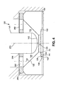
- Fig.4 is a side view, in section, of a discharge end of an injector according to a second preferred embodiment of the present invention;
- Fig.5 is a top plan view of a metering orifice used in the injector shown in Fig.4; and
- Fig.6 is a side view, in section, of a discharge end of an injector according to a third preferred embodiment of the present invention.
-
- In the drawings, like numerals are used to indicate like elements throughout. A first preferred embodiment, shown in Figs.1 and 2, is a
fuel injector 10 for use in a fuel injection system of an internal combustion engine. Theinjector 10 includes ahousing 20, avalve seat 30, aneedle 40, and a generally planarfuel metering orifice 50. Details of the operation of thefuel injector 10 in relation to the operation of the internal combustion engine (not shown) are well known and will not be described in detail herein, except as the operation relates to the preferred embodiments. Although the preferred embodiments are generally directed to injectors for internal combustion engines, those skilled in the art will recognize from present disclosure that the preferred embodiments can be adapted for other applications in which precise metering of fluids is desired or required. - The
valve housing 20 has an upstream orinlet end 210 and a downstream oroutlet end 220. Thehousing 20 further includes avalve body 260, which includes ahousing chamber 262. The words "upstream" and "downstream" designate flow directions in the drawings to which reference is made. The upstream side is toward the top of each drawing and the downstream side is toward the bottom of each drawing. Thehousing chamber 262 extends through a central longitudinal portion of thevalve housing 20 along alongitudinal axis 270 extending therethrough and is formed by aninterior housing wall 264. Aneedle guide 280 having a central needle guide opening 284 and a plurality of radially spacedfuel flow openings 282 is located within thehousing chamber 262 proximate to thedownstream end 220 of thehousing 20. The needle guide assists in maintaining reciprocation of theneedle 40 along thelongitudinal axis 270. An overmold 290 constructed of a dielectric material, preferably a plastic or other suitable material, encompasses thevalve body 260. An o-ring 12 is located around the outer circumference of thevalve body 260 to seat theinjector 10 in the internal combustion engine (not shown). - The
valve seat 30 is located within thehousing chamber 262 proximate to theoutlet end 220 between theneedle guide 280 and thedischarge ends 220. Thevalve seat 30 includes apassage orifice 320 which extends generally along thelongitudinal axis 270 of thehousing 20 and is formed by a generallycylindrical wall 322. Preferably, acenter 321 of theorifice 320 is on thelongitudinal axis 270. Thevalve seat 30 also includes abeveled sealing surface 330 which surrounds theorifice 320 and tapers radially downward and inward toward theorifice 320 such that thesealing surface 330 is oblique to thelongitudinal axis 270. The words "inward" and "outward" refer to directions towards and away from, respectively, thelongitudinal axis 270. - The
needle 40 is reciprocally located within thehousing chamber 262 generally along thelongitudinal axis 270 of thehousing 20. Theneedle 40 is reciprocable between a first, or open, position wherein theneedle 40 is displaced from the valve seat 30 (as shown in Fig.2), allowing pressurized fuel to flow downstream past theneedle 40, and a second, or closed, position wherein theneedle 40 is biased against the valve seat 30 (as shown in Fig.1) by a biasing element (not shown), preferably a spring, precluding fuel flow past theneedle 40. - The
needle 40 includes afirst portion 410 which has a first cross-sectional area A1 and asecond portion 420 which has a second cross-sectional area A2. Thesecond portion 420 includes a generally sphericalvalve contact face 422 which is sized to sealingly engage the beveledvalve sealing surface 330 when theneedle 40 is in the closed position. The sphericalvalve contact face 422 engages the beveledvalve sealing surface 330 to provide a generally line contact therebetween. The line contact provides a solid seal between theneedle 40 and thevalve seat 30 and reduces the possibility of fuel leakage past theneedle 40. Thecontact face 422, shown in enlarged Fig.2, connects with aplanar end face 426 located at a downstream tip of theneedle 40. Theend face 426 is preferably generally perpendicular to thelongitudinal axis 270 of thehousing 20. - Preferably, both the first and second cross-sectional areas A1, A2 are circular, although those skilled in the art will recognize that the first and second cross-sectional areas A1, A2 can be other shapes as well. This configuration reduces the mass of the
needle 40 while retaining a relatively large sealing diameter of thevalve contact face 422 so as to provide a relatively generous sealing area of theneedle 40 for engagement of thevalve contact face 422 when theneedle 40 is in the closed position. The increased cross-sectional area A2 of the needle also provides a larger guide surface relative to the mean needle diameter, thereby improving the wear resistance of the internal surface of the centralneedle guide opening 284. The improved wear resistance of the internal surface of the central needle guide opening 284 is due to reduced loading compared to that of a conventional base valve guide diameter which was used with prior art needles of a generally constant cross-sectional area. For example, a typical prior art needle will have a substantially continuous cylindrically shaped shaft which terminates at an end portion wherein the cross-sectional area at the upper portion of the needle may be twice as much as the cross-sectional area A2 of theneedle 40 shown in Fig.2. - The
needle 40 is reciprocable between the closed position (shown in Fig.1) and the open position (shown in Fig.2). When theneedle 40 is in the open position, a generallyannular channel 430 is formed between thevalve contact face 422 and thevalve sealing surface 330. - The
metering orifice 50 is located within thehousing chamber 262 and is connected to thehousing 20, downstream of thevalve seat 30. Themetering orifice 50 has aninterior face 510 facing thevalve seat 30 and theneedle 40, and anexterior face 520 facing the combustion chamber (not shown). A plane of themetering orifice 50 is generally parallel to the plane of theplanar end face 426. - A
virtual extension 340 of thevalve seat 30 can be projected onto themetering orifice 50 so as to intercept theinterior face 510 of themetering orifice 50 at a point "A" shown in Fig.2. Referring now to Fig.3, although eightmetering openings 530 are shown, themetering orifice 50 preferably includes between four and twelve generallycircular metering openings 530, although those skilled in the art will recognize that themetering orifice 50 can include less than four or more than twelvemetering openings 530, and that themetering openings 530 can be other shapes, such as oval or any other suitable shape. Preferably, a distance betweenadjacent metering openings 530 is at least approximately two and a half times as great as a diameter of themetering openings 530, although those skilled in the art will recognize that the distance betweenadjacent metering openings 530 can be less than that amount. Themetering orifice 50 includes a raisedportion 540 located within a perimeter determined by themetering openings 530. Preferably, in the closed position, the raisedportion 540 of themetering orifice 50 and theend face 426 are spaced from each other by between 50 microns and 250 microns, and, more preferably, by between 50 and 100 microns, although those skilled in the art will recognize that the distance can be less than 50 microns or greater than 100 microns. The raisedportion 540 is preferably circular and reduces thesac volume 60 between themetering orifice 50 and theplanar end face 426 of theneedle 40. However, those skilled in the art will recognize that the raisedportion 540 can be other shapes, such as oval. A continuousannular gap 542 is formed between the raisedportion 540 and the orifice opening 330 in thevalve seat 30. Thegap 542 allows fuel flow between themetering orifice 50 and thevalve seat 30 when theneedle 40 is in the open position. - Downstream of the
circular wall 322, thevalve seat 30 tapers along a taperedportion 350 downward and outward in an oblique manner away from theorifice 320 to a point radially past themetering openings 530, where thevalve seat 30 flattens to abottom surface 550 preferably perpendicular to thelongitudinal axis 270. Thevalve seat orifice 320 is preferably located wholly within the perimeter determined by themetering openings 530. Theinterior face 510 of themetering orifice 50 proximate to the outer perimeter of themetering orifice 50 engages thebottom surface 550 along a generally annular contact area. - Referring to Fig.2, a generally annular controlled
velocity channel 560 is formed between thetapered portion 350 of thevalve seat 30 andinterior face 510 of themetering orifice 50. Preferably, the controlledvelocity channel 560 provides a generally constant velocity, although those skilled in the art will recognize that the controlled velocity can vary throughout the length of thechannel 560. Thechannel 560 tapers outwardly from a larger height A3 at theorifice 320 to a smaller height A4 toward themetering openings 530. The reduction in the height toward themetering openings 530 maintains the fuel at a generally controlled velocity, as will be discussed in more detail below, forcing the fuel to travel in a transverse direction across themetering openings 530, where the fuel is atomized as it passes through themetering openings 530 into the combustion chamber (not shown). A generallyannular space 570 is formed between theinterior face 510 of themetering orifice 50 radially outward of themetering openings 530 and the taperedportion 350 of thevalve seat 30. - In operation, pressurized fuel is provided to the
injector 10 by a fuel pump (not shown). The pressurized fuel enters theinjector 10 and passes through a fuel filter (not shown) to thehousing chamber 262. The fuel flows through thehousing chamber 262, thefuel flow openings 284 in theguide 280 to the interface between thevalve contact face 422 and thevalve sealing surface 330. In the closed position, theneedle 40 is biased against thevalve seat 30 so that thevalve contact face 422 sealingly engages thevalve sealing surface 330, preventing flow of fuel through themetering orifice 50. - In the open position, a solenoid or other actuating device, (not shown) reciprocates the
needle 40 to an open position, removing thespherical contact face 422 of theneedle 40 from the sealingsurface 330 of thevalve seat 30 and forming the generallyannular channel 430. Pressurized fuel within thehousing chamber 262 flows past the generallyannular channel 430 formed by theneedle 40 and thevalve seat 30 and impinges on the raisedportion 540 of themetering orifice 50. The fuel then flows generally radially outward along the raisedportion 540 of themetering orifice 50 from thelongitudinal axis 270, where the flow is redirected generally downward between the raisedportion 540 and the valveseat orifice walls 322. The fuel is then directed generally radially outward from thelongitudinal axis 270 through the generallyannular channel 560 between thetapered portion 350 of thevalve seat 30 and themetering orifice 50. The fuel attains a generally high velocity at the beginning of the generallyannular channel 560. As the fuel flows outward from thelongitudinal axis 270, the perimeter of the fuel flow increases in a direct linear relationship to the distance from thelongitudinal axis 270. To maintain a generally constant area of fuel flow, the height between themetering orifice 50 and the taperedportion 350 of thevalve seat 30 must decrease (as shown in the decreased height A4 as compared to height A3 in Fig.2) according to the formula: - r1 is a radius of the fuel flow between the
longitudinal axis 270 and location A3; - h1 is a height between the
metering orifice 50 and the taperedportion 350 at location A3; - r2 is a radius of the fuel flow between the
longitudinal axis 270 and location A4; and - h2 is a height between the
metering orifice 50 and the taperedportion 350 at location A4. -
- Although a generally constant flow velocity is desired, those skilled in the art will recognize that the generally
annular channel 560 can be used to accelerate or decelerate the velocity of the fuel if desired. - As the fuel flows across the
metering openings 530, turbulence is generated within the fuel flow which reduces the spray particle size, atomizing the fuel as it flows through themetering openings 530 into the combustion chamber (not shown). - When a pre-determined amount of fuel has been injected into the combustion chamber, the solenoid or other actuating device disengages, allowing the spring (not shown) to bias the
needle 40 to the closed position, closing the generallyannular channel 430 and seating thevalve contact face 422 of theneedle 40 onto the sealingsurface 330 of thevalve seat 30. - A
second embodiment 100 is shown in Fig.4. In the second embodiment, thevalve seat 130 includes avalve sealing surface 132 and avalve orifice 134. Thevalve seat 130 is generally the same shape as thevalve seat 30, with a taperedportion 136 which extends downward and outward in an oblique manner from thelongitudinal axis 270 downstream from thevalve orifice 134. The taperedportion 134 terminates at a location radially outward of themetering orifice openings 152. A generally annular controlledvelocity channel 154 is formed between themetering orifice 150 radially outward of themetering openings 152 and the taperedportion 136 of thevalve seat 130. - The
needle 140 differs from theneedle 40 in the first embodiment in that theneedle tip 142 does not include a flat end face. However, those skilled in the art will recognize that either of theneedles needle 140 is in the closed position, theneedle tip 142 engages thevalve seat 130 in a generally circular point contact. When theneedle 140 is in the open position, a generallyannular channel 144 is formed between theneedle 140 and thevalve seat 130. - The
metering orifice 150, shown in a top plan view in Fig.5, is generally planar and extends in a plane generally perpendicular to thelongitudinal axis 270. Themetering orifice 150 differs from themetering orifice 50 in that themetering orifice 150 does not include a raisedportion 540. - In operation, when the
needle 140 is lifted from thevalve seat 130, pressurized fuel flows through thechannel 144 formed between theneedle 140 and thevalve seat 130. The fuel is directed into thevalve seat orifice 134 and to themetering orifice 150. The fuel then is directed outward from thelongitudinal axis 270 into the controlledvelocity channel 154 where the fuel attains a high velocity at the entrance of the controlledvelocity channel 154. The high fuel velocity directs the fuel across themetering orifice 150 and theorifice openings 152 in a transverse direction to theorifice openings 152, generating turbulence within the fuel which atomizes the fuel as the fuel travels through theorifice openings 152. - The third embodiment, shown in Fig.6, is similar to the second embodiment with the exception that, in the third embodiment, a
metering orifice 600 betweenorifice openings 610 is generally rounded such that aconcave surface 620 faces theneedle 140. Thevalve seat 700, instead of tapering downward and outward in an oblique manner away from thelongitudinal axis 270 below avalve seat orifice 710 along abottom portion 720, preferably extends away from thelongitudinal axis 270 generally perpendicular to thelongitudinal axis 270. A generallyannular channel 630 is formed between thebottom portion 720 of thevalve seat 700 and themetering orifice 600. Thechannel 630 tapers outwardly from a larger height to a smaller height toward theorifice openings 610. A generallyannular space 640 is formed between themetering orifice 600 radially outward of themetering openings 610 and thebottom portion 720 of thevalve seat 700. - The operation of the third embodiment is similar to the operation of the second embodiment described above.
- Although the three preferred embodiments described above disclose generally annular channels formed between the valve seat and the metering orifice in which the channel tapers outwardly from a larger height to a smaller height toward the orifice openings to maintain a generally constant cross-sectional area, those skilled in the art will recognize that generally annular channels which taper outwardly from a larger height to a smaller height toward the orifice openings can be formed in other manners.
- Preferably, in each of the embodiments described above, the
valve seat 30, theneedle 40, and themetering orifice 50 are each constructed from stainless steel. However, those skilled in the art will recognize that thevalve seat 30, theneedle 40 and themetering orifice 50 can be constructed of other, suitable materials. - It will be appreciated by those skilled in the art that changes could be made to the embodiments described above without departing from the broad inventive concept thereof. It is understood, therefore, that this invention is not limited to the particular embodiments disclosed, but it is intended to cover modifications within the spirit and scope of the present invention as defined in the appended claims.
Claims (15)
- A fuel injector comprising:a housing having an inlet, an outlet and a longitudinal axis extending therethrough;a valve seat disposed proximate the outlet, the valve seat including a sealing surface and an orifice;a metering orifice located at the outlet, the metering orifice having a plurality of metering openings extending therethrough;a needle being reciprocally located within the housing along the longitudinal axis between a first position wherein the needle is displaced from the valve seat, allowing fuel flow past the needle, and a second position wherein the needle is biased against the valve seat, precluding fuel flow past the needle; anda controlled velocity channel formed between the valve seat and the metering orifice, the controlled velocity channel extending outwardly from the orifice to the plurality of metering openings.
- The fuel injector according to claim 1, wherein the controlled velocity channel is a generally annular channel tapering outwardly from a larger height to a smaller height toward the metering openings.
- The fuel injector according to claim 1, wherein the metering orifice is generally planar and perpendicular to the longitudinal axis.
- The fuel injector according to claim 3, wherein the metering orifice includes a raised portion between the metering openings.
- The fuel injector according to claim 4, wherein the needle includes a generally planar end face generally perpendicular to the longitudinal axis.
- The fuel injector according to claim 5, wherein, when the needle is in the second position, the end face is spaced from the raised portion by a distance of between 50 microns and 100 microns.
- The fuel injector according to claim 3, wherein the needle includes a generally rounded end face.
- The fuel injector according to claim 7, wherein the metering orifice is generally rounded.
- The fuel injector according to claim 1, wherein the needle has a generally planar end face generally perpendicular to the longitudinal axis.
- The fuel injector according to claim 9, wherein, when the needle is in the second position, the end face is spaced from the metering orifice by a distance of approximately between 50 microns and 100 microns.
- The fuel injector according to claim 1, wherein a first virtual circle defined by a virtual extension of the valve seat onto the metering orifice has a smaller diameter than a second virtual circle defined by the plurality of metering openings.
- The fuel injector according to claim 1, wherein fuel flow across the metering plate is generally transverse to each of the plurality of metering openings.
- The fuel injector according to claim 1, wherein a distance between adjacent metering openings is at least approximately two and a half times a diameter of each of the metering openings.
- A method of generating turbulence in a fuel flow through a fuel injector, the method including the steps of:providing a fuel flow under pressure to the fuel injector;opening a valve in the fuel injector and allowing the pressurized fuel to flow past the valve and into an orifice;directing the fuel flow at an initial velocity from the orifice into a controlled velocity channel formed by a valve seat and a metering orifice, the fuel generally maintaining a controlled velocity through the controlled velocity channel, the controlled velocity generating turbulence within the fuel flow; anddirecting the fuel flow through at least one orifice opening downstream of the controlled velocity channel and out of the fuel injector.
- The method according to claim 14, wherein the controlled velocity channel tapers from a first height at an upstream end of the controlled velocity channel to a second height at a downstream end of the controlled velocity channel, the second height being smaller than the first height.
Applications Claiming Priority (2)
| Application Number | Priority Date | Filing Date | Title |
|---|---|---|---|
| US568464 | 1995-12-07 | ||
| US09/568,464 US6742727B1 (en) | 2000-05-10 | 2000-05-10 | Injection valve with single disc turbulence generation |
Publications (2)
| Publication Number | Publication Date |
|---|---|
| EP1154151A1 true EP1154151A1 (en) | 2001-11-14 |
| EP1154151B1 EP1154151B1 (en) | 2004-10-27 |
Family
ID=24271403
Family Applications (1)
| Application Number | Title | Priority Date | Filing Date |
|---|---|---|---|
| EP20010201450 Expired - Lifetime EP1154151B1 (en) | 2000-05-10 | 2001-04-20 | Injection valve with single disc turbulence generation |
Country Status (4)
| Country | Link |
|---|---|
| US (4) | US6742727B1 (en) |
| EP (1) | EP1154151B1 (en) |
| JP (1) | JP4653337B2 (en) |
| DE (1) | DE60106668T2 (en) |
Cited By (11)
| Publication number | Priority date | Publication date | Assignee | Title |
|---|---|---|---|---|
| WO2002099271A1 (en) * | 2001-06-06 | 2002-12-12 | Siemens Vdo Automotive Corporation | Spray pattern control with non-angled orifices in fuel injection metering disc |
| FR2844833A1 (en) * | 2002-09-25 | 2004-03-26 | Siemens Vdo Automotive Corp | Fuel injector for automotive fuel system, has metering orifices which are extended parallel to longitudinal axis between second channel surface and outer surface such that magnetic actuator is energized to move closure member |
| FR2844831A1 (en) * | 2002-09-25 | 2004-03-26 | Siemens Vdo Automotive Corp | Fuel injector for automotive fuel system, has metering orifices which are extended parallel to longitudinal axis between second channel surface and outer surface such that magnetic actuator is energized to move closure member |
| WO2004063555A1 (en) * | 2003-01-09 | 2004-07-29 | Siemens Vdo Automotive Corporation | Spray pattern control with non-angled orifices formed on a generally planar metering disc and reoriented on subsequently dimpled fuel injection metering disc |
| US6820826B2 (en) | 2002-09-25 | 2004-11-23 | Siemens Vdo Automotive Corp. | Spray targeting to an arcuate sector with non-angled orifices in fuel injection metering disc and method |
| EP1375902A3 (en) * | 2002-06-28 | 2005-07-27 | Siemens VDO Automotive Corporation | Spray control with non-angled orifices in fuel injection metering disc and methods |
| EP1375903A3 (en) * | 2002-06-28 | 2005-07-27 | Siemens VDO Automotive Corporation | Spray pattern and spray distribution control with non-angled orifices in fuel injection metering disc and methods |
| US7086615B2 (en) | 2004-05-19 | 2006-08-08 | Siemens Vdo Automotive Corporation | Fuel injector including an orifice disc and a method of forming an oblique spiral fuel flow |
| WO2006095706A1 (en) | 2005-03-09 | 2006-09-14 | Keihin Corporation | Fuel injection valve |
| US7201329B2 (en) | 2004-04-30 | 2007-04-10 | Siemens Vdo Automotive Corporation | Fuel injector including a compound angle orifice disc for adjusting spray targeting |
| CN104520577A (en) * | 2012-08-09 | 2015-04-15 | 三菱电机株式会社 | Fuel injection valve |
Families Citing this family (40)
| Publication number | Priority date | Publication date | Assignee | Title |
|---|---|---|---|---|
| US6820598B2 (en) | 2002-03-22 | 2004-11-23 | Chrysalis Technologies Incorporated | Capillary fuel injector with metering valve for an internal combustion engine |
| US7357124B2 (en) * | 2002-05-10 | 2008-04-15 | Philip Morris Usa Inc. | Multiple capillary fuel injector for an internal combustion engine |
| JP3784748B2 (en) * | 2002-05-17 | 2006-06-14 | 株式会社ケーヒン | Fuel injection valve |
| US7108206B2 (en) * | 2002-12-04 | 2006-09-19 | Caterpillar Inc. | Valve assembly and fuel injector using same |
| DE10319694A1 (en) * | 2003-05-02 | 2004-12-02 | Robert Bosch Gmbh | Fuel injector |
| US7004138B2 (en) | 2003-07-15 | 2006-02-28 | Eaton Corporation | Pressure pulse communication in an engine intake manifold |
| JP2005113815A (en) * | 2003-10-08 | 2005-04-28 | Keihin Corp | Fuel injection valve |
| US7337768B2 (en) * | 2004-05-07 | 2008-03-04 | Philip Morris Usa Inc. | Multiple capillary fuel injector for an internal combustion engine |
| DE102004049281A1 (en) * | 2004-10-09 | 2006-04-20 | Robert Bosch Gmbh | Fuel injector |
| DE102004049278A1 (en) * | 2004-10-09 | 2006-04-13 | Robert Bosch Gmbh | Fuel injector |
| US7051957B1 (en) * | 2004-11-05 | 2006-05-30 | Visteon Global Technologies, Inc. | Low pressure fuel injector nozzle |
| US7198207B2 (en) * | 2004-11-05 | 2007-04-03 | Visteon Global Technologies, Inc. | Low pressure fuel injector nozzle |
| US7104475B2 (en) * | 2004-11-05 | 2006-09-12 | Visteon Global Technologies, Inc. | Low pressure fuel injector nozzle |
| US7137577B2 (en) * | 2004-11-05 | 2006-11-21 | Visteon Global Technologies, Inc. | Low pressure fuel injector nozzle |
| US7168637B2 (en) * | 2004-11-05 | 2007-01-30 | Visteon Global Technologies, Inc. | Low pressure fuel injector nozzle |
| US7438241B2 (en) * | 2004-11-05 | 2008-10-21 | Visteon Global Technologies, Inc. | Low pressure fuel injector nozzle |
| US7185831B2 (en) * | 2004-11-05 | 2007-03-06 | Ford Motor Company | Low pressure fuel injector nozzle |
| US7124963B2 (en) * | 2004-11-05 | 2006-10-24 | Visteon Global Technologies, Inc. | Low pressure fuel injector nozzle |
| JP4079144B2 (en) * | 2004-12-20 | 2008-04-23 | 株式会社豊田中央研究所 | Fuel injection valve |
| US20060157595A1 (en) * | 2005-01-14 | 2006-07-20 | Peterson William A Jr | Fuel injector for high fuel flow rate applications |
| US20080185460A1 (en) * | 2005-07-29 | 2008-08-07 | Mitsubishi Electric Corporation | Fuel Injection Valve |
| JP4657143B2 (en) * | 2006-05-15 | 2011-03-23 | 株式会社ケーヒン | Fuel injection valve |
| JP4218696B2 (en) * | 2006-05-19 | 2009-02-04 | トヨタ自動車株式会社 | Fuel injection nozzle |
| EP1882844A1 (en) * | 2006-07-25 | 2008-01-30 | Siemens Aktiengesellschaft | Valve assembly for an Injection valve and injection valve |
| WO2008093387A1 (en) * | 2007-01-29 | 2008-08-07 | Mitsubishi Electric Corporation | Fuel injection valve |
| JP4618262B2 (en) * | 2007-03-16 | 2011-01-26 | 三菱電機株式会社 | Fuel injection valve |
| WO2008117459A1 (en) | 2007-03-27 | 2008-10-02 | Mitsubishi Electric Corporation | Fuel injection valve |
| JP4548448B2 (en) * | 2007-05-24 | 2010-09-22 | 株式会社デンソー | Fuel injection valve |
| US20090057446A1 (en) * | 2007-08-29 | 2009-03-05 | Visteon Global Technologies, Inc. | Low pressure fuel injector nozzle |
| US7669789B2 (en) * | 2007-08-29 | 2010-03-02 | Visteon Global Technologies, Inc. | Low pressure fuel injector nozzle |
| US20090090794A1 (en) * | 2007-10-04 | 2009-04-09 | Visteon Global Technologies, Inc. | Low pressure fuel injector |
| US20090200403A1 (en) * | 2008-02-08 | 2009-08-13 | David Ling-Shun Hung | Fuel injector |
| JP5875442B2 (en) * | 2012-03-30 | 2016-03-02 | 日立オートモティブシステムズ株式会社 | Fuel injection valve |
| CN104334865A (en) * | 2012-05-11 | 2015-02-04 | 丰田自动车株式会社 | Fuel injection valve and fuel injection device with same |
| US20150211458A1 (en) * | 2012-08-01 | 2015-07-30 | 3M Innovative Properties Company | Targeting of fuel output by off-axis directing of nozzle output streams |
| JP6138502B2 (en) * | 2013-02-04 | 2017-05-31 | 日立オートモティブシステムズ株式会社 | Fuel injection valve |
| US9850869B2 (en) * | 2013-07-22 | 2017-12-26 | Delphi Technologies, Inc. | Fuel injector |
| CN107208593B (en) * | 2015-01-30 | 2020-04-14 | 日立汽车系统株式会社 | Fuel injection valve |
| JP6749148B2 (en) * | 2016-06-10 | 2020-09-02 | 日立オートモティブシステムズ株式会社 | Fuel injector |
| US11524887B2 (en) * | 2021-04-15 | 2022-12-13 | Keith Lauster Davis | Liquid container tilting apparatus and method |
Citations (7)
| Publication number | Priority date | Publication date | Assignee | Title |
|---|---|---|---|---|
| US4101074A (en) * | 1976-06-17 | 1978-07-18 | The Bendix Corporation | Fuel inlet assembly for a fuel injection valve |
| US4532906A (en) * | 1982-08-10 | 1985-08-06 | Robert Bosch Gmbh | Fuel supply system |
| US5449114A (en) * | 1993-08-06 | 1995-09-12 | Ford Motor Company | Method and structure for optimizing atomization quality of a low pressure fuel injector |
| US5730368A (en) * | 1994-09-30 | 1998-03-24 | Robert Bosch Gmbh | Nozzle plate, particularly for injection valves and processes for manufacturing a nozzle plate |
| US5766441A (en) * | 1995-03-29 | 1998-06-16 | Robert Bosch Gmbh | Method for manfacturing an orifice plate |
| US5931391A (en) * | 1996-10-25 | 1999-08-03 | Denso Corporation | Fluid injection valve |
| EP1092865A1 (en) * | 1999-10-13 | 2001-04-18 | Siemens Automotive Corporation | Fuel injection valve with multiple nozzle plates |
Family Cites Families (33)
| Publication number | Priority date | Publication date | Assignee | Title |
|---|---|---|---|---|
| US4057190A (en) * | 1976-06-17 | 1977-11-08 | Bendix Corporation | Fuel break-up disc for injection valve |
| GB1600631A (en) * | 1978-01-10 | 1981-10-21 | Binks Bullows Ltd | Spray nozzle |
| US4925110A (en) * | 1987-12-28 | 1990-05-15 | Toyota Jidosha Kabushiki Kaisha | Fuel injection valve for an internal combustion engine having a pillar opposing a fuel injection hole |
| DE8802464U1 (en) | 1988-02-25 | 1989-06-22 | Robert Bosch Gmbh, 7000 Stuttgart, De | |
| DE3919231C2 (en) | 1989-06-13 | 1997-03-06 | Bosch Gmbh Robert | Fuel injection device for internal combustion engines |
| DE4104019C1 (en) * | 1991-02-09 | 1992-04-23 | Robert Bosch Gmbh, 7000 Stuttgart, De | |
| US5383597A (en) * | 1993-08-06 | 1995-01-24 | Ford Motor Company | Apparatus and method for controlling the cone angle of an atomized spray from a low pressure fuel injector |
| DE4328418A1 (en) * | 1993-08-24 | 1995-03-02 | Bosch Gmbh Robert | Solenoid fuel injection valve |
| US5494124A (en) * | 1993-10-08 | 1996-02-27 | Vortexx Group, Inc. | Negative pressure vortex nozzle |
| US5484108A (en) * | 1994-03-31 | 1996-01-16 | Siemens Automotive L.P. | Fuel injector having novel multiple orifice disk members |
| DE19503269A1 (en) * | 1995-02-02 | 1996-08-08 | Bosch Gmbh Robert | Fuel injection valve for internal combustion engines |
| WO1996030643A1 (en) * | 1995-03-29 | 1996-10-03 | Robert Bosch Gmbh | Perforated disc, especially for injection valves |
| DE59611321D1 (en) * | 1995-03-29 | 2006-03-30 | Bosch Gmbh Robert | Perforated disk, in particular for injection valves and method for producing a perforated disk |
| JP3183156B2 (en) * | 1995-04-27 | 2001-07-03 | 株式会社デンソー | Fluid injection nozzle |
| JP3156554B2 (en) | 1995-07-24 | 2001-04-16 | トヨタ自動車株式会社 | Fuel injection valve |
| DE19527626A1 (en) | 1995-07-28 | 1997-01-30 | Bosch Gmbh Robert | Fuel injector |
| DE19527846A1 (en) * | 1995-07-29 | 1997-01-30 | Bosch Gmbh Robert | Valve, in particular fuel injector |
| GB2307939B (en) | 1995-12-09 | 2000-06-14 | Weatherford Oil Tool | Apparatus for gripping a pipe |
| DE19547406B4 (en) * | 1995-12-19 | 2007-10-31 | Robert Bosch Gmbh | Fuel injector |
| US5765750A (en) * | 1996-07-26 | 1998-06-16 | Siemens Automotive Corporation | Method and apparatus for controlled atomization in a fuel injector for an internal combustion engine |
| DE19631066A1 (en) * | 1996-08-01 | 1998-02-05 | Bosch Gmbh Robert | Fuel injector |
| DE19703200A1 (en) * | 1997-01-30 | 1998-08-06 | Bosch Gmbh Robert | Fuel injector |
| JPH11200998A (en) * | 1998-01-19 | 1999-07-27 | Denso Corp | Fluid injection nozzle |
| DE19815795A1 (en) * | 1998-04-08 | 1999-10-14 | Bosch Gmbh Robert | Atomizer disc and fuel injector with atomizer disc |
| DE19815781A1 (en) * | 1998-04-08 | 1999-10-14 | Bosch Gmbh Robert | Fuel injector |
| JP3777259B2 (en) | 1998-09-24 | 2006-05-24 | 株式会社ケーヒン | Electromagnetic fuel injection valve |
| US6102299A (en) * | 1998-12-18 | 2000-08-15 | Siemens Automotive Corporation | Fuel injector with impinging jet atomizer |
| JP2001046919A (en) | 1999-08-06 | 2001-02-20 | Denso Corp | Fluid injection nozzle |
| US6575382B1 (en) * | 1999-09-13 | 2003-06-10 | Delphi Technologies, Inc. | Fuel injection with air blasted sheeted spray |
| JP2002039036A (en) | 2000-07-24 | 2002-02-06 | Mitsubishi Electric Corp | Fuel injection valve |
| US6848635B2 (en) * | 2002-01-31 | 2005-02-01 | Visteon Global Technologies, Inc. | Fuel injector nozzle assembly with induced turbulence |
| US7191961B2 (en) * | 2002-11-29 | 2007-03-20 | Denso Corporation | Injection hole plate and fuel injection apparatus having the same |
| WO2004063556A2 (en) * | 2003-01-09 | 2004-07-29 | Siemens Vdo Automotive Corporation | Spray pattern control with non-angled orifices formed on a dimpled fuel injection metering disc having a sac volume reducer |
-
2000
- 2000-05-10 US US09/568,464 patent/US6742727B1/en not_active Expired - Lifetime
-
2001
- 2001-04-20 DE DE60106668T patent/DE60106668T2/en not_active Expired - Lifetime
- 2001-04-20 EP EP20010201450 patent/EP1154151B1/en not_active Expired - Lifetime
- 2001-05-08 JP JP2001137685A patent/JP4653337B2/en not_active Expired - Fee Related
-
2002
- 2002-06-03 US US10/097,627 patent/US6786423B2/en not_active Expired - Lifetime
- 2002-09-20 US US10/247,351 patent/US6729563B2/en not_active Expired - Lifetime
-
2004
- 2004-03-24 US US10/807,336 patent/US7980485B2/en not_active Expired - Fee Related
Patent Citations (7)
| Publication number | Priority date | Publication date | Assignee | Title |
|---|---|---|---|---|
| US4101074A (en) * | 1976-06-17 | 1978-07-18 | The Bendix Corporation | Fuel inlet assembly for a fuel injection valve |
| US4532906A (en) * | 1982-08-10 | 1985-08-06 | Robert Bosch Gmbh | Fuel supply system |
| US5449114A (en) * | 1993-08-06 | 1995-09-12 | Ford Motor Company | Method and structure for optimizing atomization quality of a low pressure fuel injector |
| US5730368A (en) * | 1994-09-30 | 1998-03-24 | Robert Bosch Gmbh | Nozzle plate, particularly for injection valves and processes for manufacturing a nozzle plate |
| US5766441A (en) * | 1995-03-29 | 1998-06-16 | Robert Bosch Gmbh | Method for manfacturing an orifice plate |
| US5931391A (en) * | 1996-10-25 | 1999-08-03 | Denso Corporation | Fluid injection valve |
| EP1092865A1 (en) * | 1999-10-13 | 2001-04-18 | Siemens Automotive Corporation | Fuel injection valve with multiple nozzle plates |
Cited By (25)
| Publication number | Priority date | Publication date | Assignee | Title |
|---|---|---|---|---|
| WO2002099271A1 (en) * | 2001-06-06 | 2002-12-12 | Siemens Vdo Automotive Corporation | Spray pattern control with non-angled orifices in fuel injection metering disc |
| US6769625B2 (en) | 2001-06-06 | 2004-08-03 | Siemens Vdo Automotive Corporation | Spray pattern control with non-angled orifices in fuel injection metering disc |
| EP1375903A3 (en) * | 2002-06-28 | 2005-07-27 | Siemens VDO Automotive Corporation | Spray pattern and spray distribution control with non-angled orifices in fuel injection metering disc and methods |
| EP1375902A3 (en) * | 2002-06-28 | 2005-07-27 | Siemens VDO Automotive Corporation | Spray control with non-angled orifices in fuel injection metering disc and methods |
| FR2844833A1 (en) * | 2002-09-25 | 2004-03-26 | Siemens Vdo Automotive Corp | Fuel injector for automotive fuel system, has metering orifices which are extended parallel to longitudinal axis between second channel surface and outer surface such that magnetic actuator is energized to move closure member |
| FR2844831A1 (en) * | 2002-09-25 | 2004-03-26 | Siemens Vdo Automotive Corp | Fuel injector for automotive fuel system, has metering orifices which are extended parallel to longitudinal axis between second channel surface and outer surface such that magnetic actuator is energized to move closure member |
| DE10343659B4 (en) * | 2002-09-25 | 2008-04-03 | Siemens Vdo Automotive Corporation, Auburn Hills | Aiming beams at an arcuate sector with non-angled openings in a fuel injection metering disk |
| DE10343596B4 (en) * | 2002-09-25 | 2008-03-13 | Siemens VDO Automotive Corporation, (n.d.Ges.d. Staates Delaware), Auburn Hills | Control for generally circular spray patterns with non-angled openings in a fuel injection metering disk |
| US7159800B2 (en) | 2002-09-25 | 2007-01-09 | Siemens Vdo Automotive Corporation | Spray pattern control with angular orientation in fuel injector and method |
| US6929197B2 (en) | 2002-09-25 | 2005-08-16 | Siemens Vdo Automotive Corporation | Generally circular spray pattern control with non-angled orifices in fuel injection metering disc and method |
| US6789754B2 (en) | 2002-09-25 | 2004-09-14 | Siemens Vdo Automotive Corporation | Spray pattern control with angular orientation in fuel injector and method |
| US6820826B2 (en) | 2002-09-25 | 2004-11-23 | Siemens Vdo Automotive Corp. | Spray targeting to an arcuate sector with non-angled orifices in fuel injection metering disc and method |
| US6921022B2 (en) | 2003-01-09 | 2005-07-26 | Siemens Vdo Automotive Corporation | Spray pattern control with non-angled orifices formed on dimpled fuel injection metering disc having a sac volume reducer |
| US6921021B2 (en) | 2003-01-09 | 2005-07-26 | Siemens Vdo Automotive Corporation | Spray pattern control with non-angled orifices formed on a dimpled fuel injection metering disc having a sac volume reducer |
| WO2004063556A3 (en) * | 2003-01-09 | 2004-11-04 | Siemens Vdo Automotive Corp | Spray pattern control with non-angled orifices formed on a dimpled fuel injection metering disc having a sac volume reducer |
| WO2004063554A3 (en) * | 2003-01-09 | 2004-09-02 | Siemens Vdo Automotive Corp | Spray pattern control with non-angled orifices formed on dimpled fuel injection metering disc having a sac volume reducer |
| US6966499B2 (en) | 2003-01-09 | 2005-11-22 | Siemens Vdo Automotive Corporation | Spray pattern control with non-angled orifices formed on a generally planar metering disc and reoriented on subsequently dimpled fuel injection metering disc |
| WO2004063556A2 (en) * | 2003-01-09 | 2004-07-29 | Siemens Vdo Automotive Corporation | Spray pattern control with non-angled orifices formed on a dimpled fuel injection metering disc having a sac volume reducer |
| WO2004063554A2 (en) * | 2003-01-09 | 2004-07-29 | Siemens Vdo Automotive Corporation | Spray pattern control with non-angled orifices formed on dimpled fuel injection metering disc having a sac volume reducer |
| WO2004063555A1 (en) * | 2003-01-09 | 2004-07-29 | Siemens Vdo Automotive Corporation | Spray pattern control with non-angled orifices formed on a generally planar metering disc and reoriented on subsequently dimpled fuel injection metering disc |
| US7201329B2 (en) | 2004-04-30 | 2007-04-10 | Siemens Vdo Automotive Corporation | Fuel injector including a compound angle orifice disc for adjusting spray targeting |
| US7086615B2 (en) | 2004-05-19 | 2006-08-08 | Siemens Vdo Automotive Corporation | Fuel injector including an orifice disc and a method of forming an oblique spiral fuel flow |
| WO2006095706A1 (en) | 2005-03-09 | 2006-09-14 | Keihin Corporation | Fuel injection valve |
| CN104520577A (en) * | 2012-08-09 | 2015-04-15 | 三菱电机株式会社 | Fuel injection valve |
| CN104520577B (en) * | 2012-08-09 | 2018-01-23 | 三菱电机株式会社 | Fuelinjection nozzle |
Also Published As
| Publication number | Publication date |
|---|---|
| DE60106668T2 (en) | 2005-03-17 |
| JP2002004983A (en) | 2002-01-09 |
| US20040195390A1 (en) | 2004-10-07 |
| EP1154151B1 (en) | 2004-10-27 |
| DE60106668D1 (en) | 2004-12-02 |
| US6786423B2 (en) | 2004-09-07 |
| US20020130193A1 (en) | 2002-09-19 |
| US7980485B2 (en) | 2011-07-19 |
| US20030057300A1 (en) | 2003-03-27 |
| US6742727B1 (en) | 2004-06-01 |
| US6729563B2 (en) | 2004-05-04 |
| JP4653337B2 (en) | 2011-03-16 |
Similar Documents
| Publication | Publication Date | Title |
|---|---|---|
| EP1154151B1 (en) | Injection valve with single disc turbulence generation | |
| US6357677B1 (en) | Fuel injection valve with multiple nozzle plates | |
| EP1581739B1 (en) | Spray pattern control with non-angled orifices formed on dimpled fuel injection metering disc having a sac volume reducer | |
| US7299997B2 (en) | Fuel injector with sauter-mean-diameter atomization spray of less than 70 microns | |
| US5996912A (en) | Flat needle for pressurized swirl fuel injector | |
| US6360960B1 (en) | Fuel injector sac volume reducer | |
| US6789754B2 (en) | Spray pattern control with angular orientation in fuel injector and method | |
| US20030015595A1 (en) | Spray pattern control with non-angled orifices in fuel injection metering disc | |
| JP2004518910A (en) | Fuel injection valve | |
| US20060157595A1 (en) | Fuel injector for high fuel flow rate applications | |
| US6764027B2 (en) | Fuel injection valve | |
| JP4100286B2 (en) | Fluid injection valve | |
| US6328222B1 (en) | Pulsed air assist valve module | |
| JP2001227434A (en) | Fuel injection nozzle | |
| KR20010085602A (en) | Fluid injection nozzle | |
| JPH0354361A (en) | Fuel injection device of internal combustion engine |
Legal Events
| Date | Code | Title | Description |
|---|---|---|---|
| PUAI | Public reference made under article 153(3) epc to a published international application that has entered the european phase |
Free format text: ORIGINAL CODE: 0009012 |
|
| 17P | Request for examination filed |
Effective date: 20010913 |
|
| AK | Designated contracting states |
Kind code of ref document: A1 Designated state(s): DE FR GB IT Kind code of ref document: A1 Designated state(s): AT BE CH CY DE DK ES FI FR GB GR IE IT LI LU MC NL PT SE TR |
|
| AX | Request for extension of the european patent |
Free format text: AL;LT;LV;MK;RO;SI |
|
| AKX | Designation fees paid |
Free format text: DE FR GB IT |
|
| 17Q | First examination report despatched |
Effective date: 20021213 |
|
| RAP1 | Party data changed (applicant data changed or rights of an application transferred) |
Owner name: SIEMENS VDO AUTOMOTIVE CORPORATION |
|
| GRAP | Despatch of communication of intention to grant a patent |
Free format text: ORIGINAL CODE: EPIDOSNIGR1 |
|
| GRAS | Grant fee paid |
Free format text: ORIGINAL CODE: EPIDOSNIGR3 |
|
| GRAA | (expected) grant |
Free format text: ORIGINAL CODE: 0009210 |
|
| AK | Designated contracting states |
Kind code of ref document: B1 Designated state(s): DE FR GB IT |
|
| REG | Reference to a national code |
Ref country code: GB Ref legal event code: FG4D |
|
| RIN1 | Information on inventor provided before grant (corrected) |
Inventor name: PETERSON, WILLIAM A. JNR. |
|
| REF | Corresponds to: |
Ref document number: 60106668 Country of ref document: DE Date of ref document: 20041202 Kind code of ref document: P |
|
| ET | Fr: translation filed | ||
| PLBE | No opposition filed within time limit |
Free format text: ORIGINAL CODE: 0009261 |
|
| STAA | Information on the status of an ep patent application or granted ep patent |
Free format text: STATUS: NO OPPOSITION FILED WITHIN TIME LIMIT |
|
| 26N | No opposition filed |
Effective date: 20050728 |
|
| PGFP | Annual fee paid to national office [announced via postgrant information from national office to epo] |
Ref country code: GB Payment date: 20130418 Year of fee payment: 13 |
|
| GBPC | Gb: european patent ceased through non-payment of renewal fee |
Effective date: 20140420 |
|
| PG25 | Lapsed in a contracting state [announced via postgrant information from national office to epo] |
Ref country code: GB Free format text: LAPSE BECAUSE OF NON-PAYMENT OF DUE FEES Effective date: 20140420 |
|
| REG | Reference to a national code |
Ref country code: FR Ref legal event code: PLFP Year of fee payment: 16 |
|
| REG | Reference to a national code |
Ref country code: FR Ref legal event code: PLFP Year of fee payment: 17 |
|
| PGFP | Annual fee paid to national office [announced via postgrant information from national office to epo] |
Ref country code: DE Payment date: 20170430 Year of fee payment: 17 Ref country code: FR Payment date: 20170419 Year of fee payment: 17 |
|
| PGFP | Annual fee paid to national office [announced via postgrant information from national office to epo] |
Ref country code: IT Payment date: 20170424 Year of fee payment: 17 |
|
| REG | Reference to a national code |
Ref country code: DE Ref legal event code: R119 Ref document number: 60106668 Country of ref document: DE |
|
| PG25 | Lapsed in a contracting state [announced via postgrant information from national office to epo] |
Ref country code: DE Free format text: LAPSE BECAUSE OF NON-PAYMENT OF DUE FEES Effective date: 20181101 |
|
| PG25 | Lapsed in a contracting state [announced via postgrant information from national office to epo] |
Ref country code: FR Free format text: LAPSE BECAUSE OF NON-PAYMENT OF DUE FEES Effective date: 20180430 Ref country code: IT Free format text: LAPSE BECAUSE OF NON-PAYMENT OF DUE FEES Effective date: 20180420 |