EP1160193A1 - Reforming apparatus - Google Patents
Reforming apparatus Download PDFInfo
- Publication number
- EP1160193A1 EP1160193A1 EP01113313A EP01113313A EP1160193A1 EP 1160193 A1 EP1160193 A1 EP 1160193A1 EP 01113313 A EP01113313 A EP 01113313A EP 01113313 A EP01113313 A EP 01113313A EP 1160193 A1 EP1160193 A1 EP 1160193A1
- Authority
- EP
- European Patent Office
- Prior art keywords
- catalyst
- steam
- oxidizer
- feeding
- controlling means
- Prior art date
- Legal status (The legal status is an assumption and is not a legal conclusion. Google has not performed a legal analysis and makes no representation as to the accuracy of the status listed.)
- Withdrawn
Links
Images


Classifications
-
- B—PERFORMING OPERATIONS; TRANSPORTING
- B01—PHYSICAL OR CHEMICAL PROCESSES OR APPARATUS IN GENERAL
- B01J—CHEMICAL OR PHYSICAL PROCESSES, e.g. CATALYSIS OR COLLOID CHEMISTRY; THEIR RELEVANT APPARATUS
- B01J8/00—Chemical or physical processes in general, conducted in the presence of fluids and solid particles; Apparatus for such processes
- B01J8/02—Chemical or physical processes in general, conducted in the presence of fluids and solid particles; Apparatus for such processes with stationary particles, e.g. in fixed beds
- B01J8/04—Chemical or physical processes in general, conducted in the presence of fluids and solid particles; Apparatus for such processes with stationary particles, e.g. in fixed beds the fluid passing successively through two or more beds
- B01J8/0492—Feeding reactive fluids
-
- B—PERFORMING OPERATIONS; TRANSPORTING
- B01—PHYSICAL OR CHEMICAL PROCESSES OR APPARATUS IN GENERAL
- B01J—CHEMICAL OR PHYSICAL PROCESSES, e.g. CATALYSIS OR COLLOID CHEMISTRY; THEIR RELEVANT APPARATUS
- B01J19/00—Chemical, physical or physico-chemical processes in general; Their relevant apparatus
- B01J19/0006—Controlling or regulating processes
- B01J19/0013—Controlling the temperature of the process
-
- B—PERFORMING OPERATIONS; TRANSPORTING
- B01—PHYSICAL OR CHEMICAL PROCESSES OR APPARATUS IN GENERAL
- B01J—CHEMICAL OR PHYSICAL PROCESSES, e.g. CATALYSIS OR COLLOID CHEMISTRY; THEIR RELEVANT APPARATUS
- B01J8/00—Chemical or physical processes in general, conducted in the presence of fluids and solid particles; Apparatus for such processes
- B01J8/02—Chemical or physical processes in general, conducted in the presence of fluids and solid particles; Apparatus for such processes with stationary particles, e.g. in fixed beds
- B01J8/04—Chemical or physical processes in general, conducted in the presence of fluids and solid particles; Apparatus for such processes with stationary particles, e.g. in fixed beds the fluid passing successively through two or more beds
- B01J8/0403—Chemical or physical processes in general, conducted in the presence of fluids and solid particles; Apparatus for such processes with stationary particles, e.g. in fixed beds the fluid passing successively through two or more beds the fluid flow within the beds being predominantly horizontal
- B01J8/0423—Chemical or physical processes in general, conducted in the presence of fluids and solid particles; Apparatus for such processes with stationary particles, e.g. in fixed beds the fluid passing successively through two or more beds the fluid flow within the beds being predominantly horizontal through two or more otherwise shaped beds
- B01J8/0438—Chemical or physical processes in general, conducted in the presence of fluids and solid particles; Apparatus for such processes with stationary particles, e.g. in fixed beds the fluid passing successively through two or more beds the fluid flow within the beds being predominantly horizontal through two or more otherwise shaped beds the beds being placed next to each other
-
- B—PERFORMING OPERATIONS; TRANSPORTING
- B01—PHYSICAL OR CHEMICAL PROCESSES OR APPARATUS IN GENERAL
- B01J—CHEMICAL OR PHYSICAL PROCESSES, e.g. CATALYSIS OR COLLOID CHEMISTRY; THEIR RELEVANT APPARATUS
- B01J8/00—Chemical or physical processes in general, conducted in the presence of fluids and solid particles; Apparatus for such processes
- B01J8/02—Chemical or physical processes in general, conducted in the presence of fluids and solid particles; Apparatus for such processes with stationary particles, e.g. in fixed beds
- B01J8/04—Chemical or physical processes in general, conducted in the presence of fluids and solid particles; Apparatus for such processes with stationary particles, e.g. in fixed beds the fluid passing successively through two or more beds
- B01J8/0496—Heating or cooling the reactor
-
- C—CHEMISTRY; METALLURGY
- C01—INORGANIC CHEMISTRY
- C01B—NON-METALLIC ELEMENTS; COMPOUNDS THEREOF; METALLOIDS OR COMPOUNDS THEREOF NOT COVERED BY SUBCLASS C01C
- C01B3/00—Hydrogen; Gaseous mixtures containing hydrogen; Separation of hydrogen from mixtures containing it; Purification of hydrogen
- C01B3/02—Production of hydrogen or of gaseous mixtures containing a substantial proportion of hydrogen
- C01B3/32—Production of hydrogen or of gaseous mixtures containing a substantial proportion of hydrogen by reaction of gaseous or liquid organic compounds with gasifying agents, e.g. water, carbon dioxide, air
- C01B3/34—Production of hydrogen or of gaseous mixtures containing a substantial proportion of hydrogen by reaction of gaseous or liquid organic compounds with gasifying agents, e.g. water, carbon dioxide, air by reaction of hydrocarbons with gasifying agents
- C01B3/38—Production of hydrogen or of gaseous mixtures containing a substantial proportion of hydrogen by reaction of gaseous or liquid organic compounds with gasifying agents, e.g. water, carbon dioxide, air by reaction of hydrocarbons with gasifying agents using catalysts
- C01B3/382—Multi-step processes
-
- C—CHEMISTRY; METALLURGY
- C01—INORGANIC CHEMISTRY
- C01B—NON-METALLIC ELEMENTS; COMPOUNDS THEREOF; METALLOIDS OR COMPOUNDS THEREOF NOT COVERED BY SUBCLASS C01C
- C01B3/00—Hydrogen; Gaseous mixtures containing hydrogen; Separation of hydrogen from mixtures containing it; Purification of hydrogen
- C01B3/02—Production of hydrogen or of gaseous mixtures containing a substantial proportion of hydrogen
- C01B3/32—Production of hydrogen or of gaseous mixtures containing a substantial proportion of hydrogen by reaction of gaseous or liquid organic compounds with gasifying agents, e.g. water, carbon dioxide, air
- C01B3/34—Production of hydrogen or of gaseous mixtures containing a substantial proportion of hydrogen by reaction of gaseous or liquid organic compounds with gasifying agents, e.g. water, carbon dioxide, air by reaction of hydrocarbons with gasifying agents
- C01B3/38—Production of hydrogen or of gaseous mixtures containing a substantial proportion of hydrogen by reaction of gaseous or liquid organic compounds with gasifying agents, e.g. water, carbon dioxide, air by reaction of hydrocarbons with gasifying agents using catalysts
- C01B3/386—Catalytic partial combustion
-
- C—CHEMISTRY; METALLURGY
- C01—INORGANIC CHEMISTRY
- C01B—NON-METALLIC ELEMENTS; COMPOUNDS THEREOF; METALLOIDS OR COMPOUNDS THEREOF NOT COVERED BY SUBCLASS C01C
- C01B3/00—Hydrogen; Gaseous mixtures containing hydrogen; Separation of hydrogen from mixtures containing it; Purification of hydrogen
- C01B3/02—Production of hydrogen or of gaseous mixtures containing a substantial proportion of hydrogen
- C01B3/32—Production of hydrogen or of gaseous mixtures containing a substantial proportion of hydrogen by reaction of gaseous or liquid organic compounds with gasifying agents, e.g. water, carbon dioxide, air
- C01B3/34—Production of hydrogen or of gaseous mixtures containing a substantial proportion of hydrogen by reaction of gaseous or liquid organic compounds with gasifying agents, e.g. water, carbon dioxide, air by reaction of hydrocarbons with gasifying agents
- C01B3/48—Production of hydrogen or of gaseous mixtures containing a substantial proportion of hydrogen by reaction of gaseous or liquid organic compounds with gasifying agents, e.g. water, carbon dioxide, air by reaction of hydrocarbons with gasifying agents followed by reaction of water vapour with carbon monoxide
-
- B—PERFORMING OPERATIONS; TRANSPORTING
- B01—PHYSICAL OR CHEMICAL PROCESSES OR APPARATUS IN GENERAL
- B01J—CHEMICAL OR PHYSICAL PROCESSES, e.g. CATALYSIS OR COLLOID CHEMISTRY; THEIR RELEVANT APPARATUS
- B01J2208/00—Processes carried out in the presence of solid particles; Reactors therefor
- B01J2208/00008—Controlling the process
- B01J2208/00017—Controlling the temperature
- B01J2208/00026—Controlling or regulating the heat exchange system
- B01J2208/00035—Controlling or regulating the heat exchange system involving measured parameters
- B01J2208/00044—Temperature measurement
- B01J2208/00061—Temperature measurement of the reactants
-
- B—PERFORMING OPERATIONS; TRANSPORTING
- B01—PHYSICAL OR CHEMICAL PROCESSES OR APPARATUS IN GENERAL
- B01J—CHEMICAL OR PHYSICAL PROCESSES, e.g. CATALYSIS OR COLLOID CHEMISTRY; THEIR RELEVANT APPARATUS
- B01J2208/00—Processes carried out in the presence of solid particles; Reactors therefor
- B01J2208/00008—Controlling the process
- B01J2208/00017—Controlling the temperature
- B01J2208/0053—Controlling multiple zones along the direction of flow, e.g. pre-heating and after-cooling
-
- B—PERFORMING OPERATIONS; TRANSPORTING
- B01—PHYSICAL OR CHEMICAL PROCESSES OR APPARATUS IN GENERAL
- B01J—CHEMICAL OR PHYSICAL PROCESSES, e.g. CATALYSIS OR COLLOID CHEMISTRY; THEIR RELEVANT APPARATUS
- B01J2208/00—Processes carried out in the presence of solid particles; Reactors therefor
- B01J2208/00008—Controlling the process
- B01J2208/00716—Means for reactor start-up
-
- B—PERFORMING OPERATIONS; TRANSPORTING
- B01—PHYSICAL OR CHEMICAL PROCESSES OR APPARATUS IN GENERAL
- B01J—CHEMICAL OR PHYSICAL PROCESSES, e.g. CATALYSIS OR COLLOID CHEMISTRY; THEIR RELEVANT APPARATUS
- B01J2219/00—Chemical, physical or physico-chemical processes in general; Their relevant apparatus
- B01J2219/00049—Controlling or regulating processes
- B01J2219/00191—Control algorithm
- B01J2219/00193—Sensing a parameter
- B01J2219/00195—Sensing a parameter of the reaction system
- B01J2219/002—Sensing a parameter of the reaction system inside the reactor
-
- B—PERFORMING OPERATIONS; TRANSPORTING
- B01—PHYSICAL OR CHEMICAL PROCESSES OR APPARATUS IN GENERAL
- B01J—CHEMICAL OR PHYSICAL PROCESSES, e.g. CATALYSIS OR COLLOID CHEMISTRY; THEIR RELEVANT APPARATUS
- B01J2219/00—Chemical, physical or physico-chemical processes in general; Their relevant apparatus
- B01J2219/00049—Controlling or regulating processes
- B01J2219/00191—Control algorithm
- B01J2219/00211—Control algorithm comparing a sensed parameter with a pre-set value
- B01J2219/00213—Fixed parameter value
-
- B—PERFORMING OPERATIONS; TRANSPORTING
- B01—PHYSICAL OR CHEMICAL PROCESSES OR APPARATUS IN GENERAL
- B01J—CHEMICAL OR PHYSICAL PROCESSES, e.g. CATALYSIS OR COLLOID CHEMISTRY; THEIR RELEVANT APPARATUS
- B01J2219/00—Chemical, physical or physico-chemical processes in general; Their relevant apparatus
- B01J2219/00049—Controlling or regulating processes
- B01J2219/00191—Control algorithm
- B01J2219/00211—Control algorithm comparing a sensed parameter with a pre-set value
- B01J2219/0022—Control algorithm comparing a sensed parameter with a pre-set value calculating difference
-
- B—PERFORMING OPERATIONS; TRANSPORTING
- B01—PHYSICAL OR CHEMICAL PROCESSES OR APPARATUS IN GENERAL
- B01J—CHEMICAL OR PHYSICAL PROCESSES, e.g. CATALYSIS OR COLLOID CHEMISTRY; THEIR RELEVANT APPARATUS
- B01J2219/00—Chemical, physical or physico-chemical processes in general; Their relevant apparatus
- B01J2219/00049—Controlling or regulating processes
- B01J2219/00191—Control algorithm
- B01J2219/00222—Control algorithm taking actions
- B01J2219/00227—Control algorithm taking actions modifying the operating conditions
- B01J2219/00229—Control algorithm taking actions modifying the operating conditions of the reaction system
- B01J2219/00231—Control algorithm taking actions modifying the operating conditions of the reaction system at the reactor inlet
-
- B—PERFORMING OPERATIONS; TRANSPORTING
- B01—PHYSICAL OR CHEMICAL PROCESSES OR APPARATUS IN GENERAL
- B01J—CHEMICAL OR PHYSICAL PROCESSES, e.g. CATALYSIS OR COLLOID CHEMISTRY; THEIR RELEVANT APPARATUS
- B01J2219/00—Chemical, physical or physico-chemical processes in general; Their relevant apparatus
- B01J2219/18—Details relating to the spatial orientation of the reactor
- B01J2219/182—Details relating to the spatial orientation of the reactor horizontal
-
- C—CHEMISTRY; METALLURGY
- C01—INORGANIC CHEMISTRY
- C01B—NON-METALLIC ELEMENTS; COMPOUNDS THEREOF; METALLOIDS OR COMPOUNDS THEREOF NOT COVERED BY SUBCLASS C01C
- C01B2203/00—Integrated processes for the production of hydrogen or synthesis gas
- C01B2203/02—Processes for making hydrogen or synthesis gas
- C01B2203/0205—Processes for making hydrogen or synthesis gas containing a reforming step
- C01B2203/0227—Processes for making hydrogen or synthesis gas containing a reforming step containing a catalytic reforming step
- C01B2203/0233—Processes for making hydrogen or synthesis gas containing a reforming step containing a catalytic reforming step the reforming step being a steam reforming step
-
- C—CHEMISTRY; METALLURGY
- C01—INORGANIC CHEMISTRY
- C01B—NON-METALLIC ELEMENTS; COMPOUNDS THEREOF; METALLOIDS OR COMPOUNDS THEREOF NOT COVERED BY SUBCLASS C01C
- C01B2203/00—Integrated processes for the production of hydrogen or synthesis gas
- C01B2203/02—Processes for making hydrogen or synthesis gas
- C01B2203/0205—Processes for making hydrogen or synthesis gas containing a reforming step
- C01B2203/0227—Processes for making hydrogen or synthesis gas containing a reforming step containing a catalytic reforming step
- C01B2203/0244—Processes for making hydrogen or synthesis gas containing a reforming step containing a catalytic reforming step the reforming step being an autothermal reforming step, e.g. secondary reforming processes
-
- C—CHEMISTRY; METALLURGY
- C01—INORGANIC CHEMISTRY
- C01B—NON-METALLIC ELEMENTS; COMPOUNDS THEREOF; METALLOIDS OR COMPOUNDS THEREOF NOT COVERED BY SUBCLASS C01C
- C01B2203/00—Integrated processes for the production of hydrogen or synthesis gas
- C01B2203/02—Processes for making hydrogen or synthesis gas
- C01B2203/025—Processes for making hydrogen or synthesis gas containing a partial oxidation step
- C01B2203/0261—Processes for making hydrogen or synthesis gas containing a partial oxidation step containing a catalytic partial oxidation step [CPO]
-
- C—CHEMISTRY; METALLURGY
- C01—INORGANIC CHEMISTRY
- C01B—NON-METALLIC ELEMENTS; COMPOUNDS THEREOF; METALLOIDS OR COMPOUNDS THEREOF NOT COVERED BY SUBCLASS C01C
- C01B2203/00—Integrated processes for the production of hydrogen or synthesis gas
- C01B2203/02—Processes for making hydrogen or synthesis gas
- C01B2203/0283—Processes for making hydrogen or synthesis gas containing a CO-shift step, i.e. a water gas shift step
-
- C—CHEMISTRY; METALLURGY
- C01—INORGANIC CHEMISTRY
- C01B—NON-METALLIC ELEMENTS; COMPOUNDS THEREOF; METALLOIDS OR COMPOUNDS THEREOF NOT COVERED BY SUBCLASS C01C
- C01B2203/00—Integrated processes for the production of hydrogen or synthesis gas
- C01B2203/06—Integration with other chemical processes
- C01B2203/066—Integration with other chemical processes with fuel cells
-
- C—CHEMISTRY; METALLURGY
- C01—INORGANIC CHEMISTRY
- C01B—NON-METALLIC ELEMENTS; COMPOUNDS THEREOF; METALLOIDS OR COMPOUNDS THEREOF NOT COVERED BY SUBCLASS C01C
- C01B2203/00—Integrated processes for the production of hydrogen or synthesis gas
- C01B2203/08—Methods of heating or cooling
- C01B2203/0805—Methods of heating the process for making hydrogen or synthesis gas
- C01B2203/0838—Methods of heating the process for making hydrogen or synthesis gas by heat exchange with exothermic reactions, other than by combustion of fuel
- C01B2203/0844—Methods of heating the process for making hydrogen or synthesis gas by heat exchange with exothermic reactions, other than by combustion of fuel the non-combustive exothermic reaction being another reforming reaction as defined in groups C01B2203/02 - C01B2203/0294
-
- C—CHEMISTRY; METALLURGY
- C01—INORGANIC CHEMISTRY
- C01B—NON-METALLIC ELEMENTS; COMPOUNDS THEREOF; METALLOIDS OR COMPOUNDS THEREOF NOT COVERED BY SUBCLASS C01C
- C01B2203/00—Integrated processes for the production of hydrogen or synthesis gas
- C01B2203/10—Catalysts for performing the hydrogen forming reactions
- C01B2203/1041—Composition of the catalyst
- C01B2203/1047—Group VIII metal catalysts
- C01B2203/1064—Platinum group metal catalysts
-
- C—CHEMISTRY; METALLURGY
- C01—INORGANIC CHEMISTRY
- C01B—NON-METALLIC ELEMENTS; COMPOUNDS THEREOF; METALLOIDS OR COMPOUNDS THEREOF NOT COVERED BY SUBCLASS C01C
- C01B2203/00—Integrated processes for the production of hydrogen or synthesis gas
- C01B2203/10—Catalysts for performing the hydrogen forming reactions
- C01B2203/1041—Composition of the catalyst
- C01B2203/1076—Copper or zinc-based catalysts
-
- C—CHEMISTRY; METALLURGY
- C01—INORGANIC CHEMISTRY
- C01B—NON-METALLIC ELEMENTS; COMPOUNDS THEREOF; METALLOIDS OR COMPOUNDS THEREOF NOT COVERED BY SUBCLASS C01C
- C01B2203/00—Integrated processes for the production of hydrogen or synthesis gas
- C01B2203/12—Feeding the process for making hydrogen or synthesis gas
- C01B2203/1205—Composition of the feed
- C01B2203/1211—Organic compounds or organic mixtures used in the process for making hydrogen or synthesis gas
- C01B2203/1217—Alcohols
- C01B2203/1223—Methanol
-
- C—CHEMISTRY; METALLURGY
- C01—INORGANIC CHEMISTRY
- C01B—NON-METALLIC ELEMENTS; COMPOUNDS THEREOF; METALLOIDS OR COMPOUNDS THEREOF NOT COVERED BY SUBCLASS C01C
- C01B2203/00—Integrated processes for the production of hydrogen or synthesis gas
- C01B2203/14—Details of the flowsheet
- C01B2203/142—At least two reforming, decomposition or partial oxidation steps in series
-
- C—CHEMISTRY; METALLURGY
- C01—INORGANIC CHEMISTRY
- C01B—NON-METALLIC ELEMENTS; COMPOUNDS THEREOF; METALLOIDS OR COMPOUNDS THEREOF NOT COVERED BY SUBCLASS C01C
- C01B2203/00—Integrated processes for the production of hydrogen or synthesis gas
- C01B2203/16—Controlling the process
- C01B2203/1604—Starting up the process
-
- C—CHEMISTRY; METALLURGY
- C01—INORGANIC CHEMISTRY
- C01B—NON-METALLIC ELEMENTS; COMPOUNDS THEREOF; METALLOIDS OR COMPOUNDS THEREOF NOT COVERED BY SUBCLASS C01C
- C01B2203/00—Integrated processes for the production of hydrogen or synthesis gas
- C01B2203/16—Controlling the process
- C01B2203/1614—Controlling the temperature
- C01B2203/1619—Measuring the temperature
-
- C—CHEMISTRY; METALLURGY
- C01—INORGANIC CHEMISTRY
- C01B—NON-METALLIC ELEMENTS; COMPOUNDS THEREOF; METALLOIDS OR COMPOUNDS THEREOF NOT COVERED BY SUBCLASS C01C
- C01B2203/00—Integrated processes for the production of hydrogen or synthesis gas
- C01B2203/16—Controlling the process
- C01B2203/169—Controlling the feed
-
- C—CHEMISTRY; METALLURGY
- C01—INORGANIC CHEMISTRY
- C01B—NON-METALLIC ELEMENTS; COMPOUNDS THEREOF; METALLOIDS OR COMPOUNDS THEREOF NOT COVERED BY SUBCLASS C01C
- C01B2203/00—Integrated processes for the production of hydrogen or synthesis gas
- C01B2203/80—Aspect of integrated processes for the production of hydrogen or synthesis gas not covered by groups C01B2203/02 - C01B2203/1695
- C01B2203/82—Several process steps of C01B2203/02 - C01B2203/08 integrated into a single apparatus
Definitions
- the present invention relates to a fuel reforming apparatus that simultaneously achieves a steam reforming reaction to produce hydrogen from a hydrocarbon and steam and a partial oxidation reaction to produce hydrogen from a hydrocarbon and an oxidizer and uses heat generated by the partial oxidation reaction that is an exothermic reaction to cover heat for the steam reforming reaction that is an endothermic reaction.
- An example of a methanol reforming apparatus for a fuel cell is disclosed in Japanese Unexamined Patent Publication No. 11-092102.
- An object of this apparatus is to spatially equalize a temperature distribution in a fuel cell reforming apparatus.
- the sixth and seventh embodiments of the disclosure temporally change an oxidizer feeding position with respect to a catalyst, to prevent a local temperature increase in the catalyst due to a continuous localized oxidation reaction, promote an internal oxidation reaction, and shorten a startup time.
- This prior art intentionally prevents a localized oxidation reaction, which is an exothermic reaction, and spatially disperses heat produced by the oxidation reaction. Accordingly, the prior art needs a large amount of fuel and time to increase the temperature of a catalyst to an activation level, and therefore, is incapable of shortening a startup time.
- An object of the present invention is to provide a fuel reforming apparatus capable of quickly heating a catalyst to an activation temperature and shortening a startup time.
- a first aspect of the present invention provides a fuel reforming apparatus that supplies, on startup, a hydrocarbon fuel and an oxidizer upstream from a second catalyst and supplies steam upstream from a first catalyst.
- the second catalyst starts a rapid oxidation reaction to produce a high-temperature gas, which quickly heats the first catalyst that is downstream of the second catalyst.
- carbon monoxide (CO) produced on the second catalyst reaches the first catalyst and reacts (a shift reaction which is an exothermic reaction) with steam on the first catalyst to promote the heating of the first catalyst.
- CO carbon monoxide
- carbon monoxide produced on the second catalyst is purified into carbon dioxide through a shift reaction on the first catalyst.
- the apparatus supplies the hydrocarbon fuel and steam upstream from the second catalyst and supplies the oxidizer upstream from the first catalyst.
- a steam reforming reaction which is an endothermic reaction, occurs on the second catalyst, to rapidly cool the second catalyst and stop reactions on the second catalyst.
- the hydrocarbon fuel and steam passed through the second catalyst without reactions cause a partial oxidation reaction and steam reforming reaction on the first catalyst that is downstream of the second catalyst, to generate a hydrogen-rich reformed gas.
- the fuel reforming apparatus of the first aspect shortens a startup time, minimizes the poisoning of a fuel cell arrangeddownstreamof the fuel reforming apparatus, and suppresses the generation of by-products that may deteriorate the quality of emissions.
- a second aspect of the present invention uses a temperature measured around the first catalyst as a parameter to determine whether or not a startup operation or an accelerating operation must be changed to a steady operation. This smoothly changes a startup operation or an accelerating operation to a steady operation while suppressing the generation of by-products.
- a third aspect of the present invention employs an integrated material feeder for each of the first and second catalysts, to feed an oxidizer and steam to the catalysts. This aspect simplifies the structure of the fuel reforming apparatus.
- a fourth aspect of the present invention applies the fuel reforming apparatus of the present invention to a fuel cell system using methanol as a fuel.
- a fifth aspect of the present invention employs an oxidation catalyst, which is commonly available, to improve the durability of the fuel reforming apparatus and reduce the cost thereof.
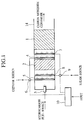
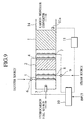
- FIG. 1 is a sectional view showing a fuel reforming apparatus according to the first embodiment of the present invention.
- a catalyst (1) 1 with a support promotes a steam reforming reaction and a partial oxidation reaction mainly in a steady operation.
- the catalyst (1) 1 is, for example, a copper-based catalyst or a palladium-based catalyst and is densely arranged without a gap in a downstream area of a reactor casing 14.
- a catalyst(2) 2 with a support promotes a partial oxidation reaction mainly in a startup operation or in a transient (accelerating) operation under increasing load.
- the catalyst(2) 2 is, for example, a copper-based catalyst, a palladium-based catalyst, or an oxidation catalyst and is densely arranged without a gap on the upstream side of the catalyst (1) 1.
- a fuel feeder 3 receives a hydrocarbon fuel such as methanol from a fuel source (not shown) and sprays or injects the fuel toward the catalyst(2) 2 that is downstream of the fuel feeder 3.
- the fuel feeder 3 is positioned upstream from the catalyst (2) 2 and is fitted to the casing 14.
- An oxidizer feeder(1) 4 receives an oxidizer from an oxidizer source (not shown) and distributes the oxidizer as uniformly as possible into a gas passage formed between the catalyst (1) 1 and the catalyst (2) 2 in the casing 14.
- the oxidizer feeder (1) 4 is fitted to the casing 14.
- An oxidizer feeder(2) 5 receives the oxidizer from the oxidizer source (not shown) and distributes the oxidizer as uniformly as possible into a gas passage formed on the upstream side of the catalyst(2) 2 in the casing 14.
- the oxidizer feeder(2) 5 is fitted to the casing 14.
- An oxidizer control valve 6 switches the oxidizer supplied from the oxidizer source (not shown) to any one of the oxidizer feeders (1) 4 and (2) 5.
- the oxidizer control valve 6 is installed in the middle of piping that connects the oxidizer source to the oxidizer feeders(1) 4 and (2) 5.
- a steam feeder(1) 7 receives steam from a steam source (not shown) and distributes the steam as uniformly as possible into the gas passage formed between the catalyst (1) 1 and the catalyst (2) 2 in the casing 14.
- the steam feeder(1) 7 is fitted to the casing 14.
- a steam feeder(2) 8 receives the steam from the steam source (not shown) and distributes the steam as uniformly as possible into the gas passage formed on the upstream side of the catalyst(2) 2 in the casing 14.
- the steam feeder(2) 8 is fitted to the casing 14.
- a steam control valve 9 switches steam supplied from the steam source (not shown) to any one of the steam feeders (1)7 and (2)8.
- the steam control valve 9 is installed in the middle of piping that connects the steam source to the steam feeders (1)7 and (2)8.
- a controller 10 is connected to the oxidizer control valve 6 and steam control valve 9 through signal lines, to separately control the valves 6 and 9.
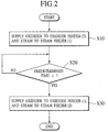
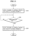
- control flow In response to an external start signal or acceleration signal, the control flow starts.
- Step S10 corresponds to a startup operation or an accelerating operation (transient operation) under increasing load.
- the controller 10 sends a switching signal to the oxidizer control valve 6 so as to connect the oxidizer source to the oxidizer feeder(2) 5.
- the controller 10 issues a switching signal to the steam control valve 9 so as to connect the steam source to the steam feeder(1) 7.
- the catalyst (2) 2 Due to the hydrocarbon fuel and oxidizer supplied from the upstream side, the catalyst (2) 2 starts an oxidation reaction (partial) to rapidly generate heat to increase the temperature of the catalyst (2) 2. This oxidation reaction generates a gas that heats the downstream catalyst (1) 1. Due to carbon monoxide produced by the oxidation reaction on the catalyst(2) 2 and the steam supplied from the upstream side, the catalyst (1) 1 starts a shift reaction to heat the catalyst (1) 1 itself. This shift reaction on the catalyst (1) 1 purifies the carbon monoxide generated by the catalyst(2) 2 into carbon dioxide and hydrogen.
- Step S20 determines whether or not a predetermined time ⁇ has passed under the state of step S10. If the time ⁇ has passed, step S30 is carried out, and if not, the state of step S10 is continued.
- the time ⁇ is determined to sufficiently bring the temperature of the catalyst(1) 1 to a threshold temperature Tc at which the catalyst (1) 1 stably achieves a steam reforming reaction and partial oxidation reaction.
- step S30 the controller 10 issues a switching signal to the oxidizer control valve 6 so as to connect the oxidizer source to the oxidizer feeder(1)4.
- the controller 10 provides a switching signal to the steam control valve 9 so as to connect the steam source to the steam feeder (2) 8.
- the catalyst(2) 2 Due to the hydrocarbon fuel and steam supplied from the upstream side, the catalyst(2) 2 starts a steam reforming reaction, which is an endothermic reaction to decrease the temperature of the catalyst(2) 2 and stop all reactions on the catalyst(2) 2. As a result, the hydrocarbon fuel and steam supplied from the upstream side of the catalyst (2) 2 pass through the catalyst (2) 2 without reactions and reach the catalyst (1) 1. Due to the hydrocarbon fuel and steam passed through the catalyst (2) 2 and the oxidizer supplied from the upstream side, the catalyst (1) 1 promotes a steam reforming reaction and partial oxidation reaction to generate a hydrogen-rich reformed gas. This completes a series of processes.
- Figures 3A to 3C show temporal changes in the supply of oxidizer and steam and temporal changes in the temperatures of the catalysts (1) and (2) in the fuel reforming apparatus of the first embodiment.
- "ON” is an oxidizer or steam source connected state and "OFF” a source disconnected state.
- the fuel reforming apparatus of the first embodiment quickly promotes an oxidation reaction (partial) on the catalyst (2) to speedily heat the catalyst (1).
- Generated carbon monoxide reacts with steam on the catalyst(1) to start a shift reaction. Consequently, the first embodiment reduces a startup time, minimizes the poisoning of a fuel cell arranged on the downstream side of the fuel reforming apparatus, and suppresses the generation of by-products that deteriorate the quality of emissions.
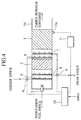
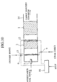
- FIG. 4 is a sectional view showing a fuel reforming apparatus according to the second embodiment of the present invention.
- the structure of the second embodiment is basically the same as that of the first embodiment and differs therefrom in that a temperature measuring unit 11 is connected to a controller 10 and a temperature sensor 11a is fitted to a reactor casing 14 in the vicinity of a catalyst (1) 1, to measure a temperature around the catalyst (1) 1. Data measured by the temperature measuring unit 11 is sent to the controller 10.
- a control operation of the fuel reforming apparatus of the second embodiment will be explained with reference to Fig. 5.
- the control operation of the second embodiment is basically the same as that of the first embodiment of Fig. 2, and therefore, only the difference of the second embodiment from the first embodiment will be explained.
- Step S20' uses a signal from the temperature measuring unit 11 to determine whether or not a temperature around the catalyst (1) 1 has reached to a predetermined temperature T. If it has reached the value T, step S30 is carried out, and if not, the state of step S10 is maintained.
- the temperature T is based on a threshold temperature Tc at which the catalyst (1) 1 stably achieves a steam reforming reaction and partial oxidation reaction.
- Tc a threshold temperature
- Figures 6A to 6C show temporal changes in the supply of oxidizer and steam and temporal changes in the temperatures of the catalysts (1) and (2) in the fuel reforming apparatus of the second embodiment.
- a status being connected to a corresponding material source is depicted as "ON", and disconnected thereto as "OFF”.
- the fuel reforming apparatus of the second embodiment uses a temperature measured in the vicinity of the catalyst(1) as a parameter to determine whether or not a steady operation must be started.
- the second embodiment further shortens a startup time and smoothly changes a startup operation or an accelerating operation to a steady operation while suppressing the generation of by-products.
- FIG. 7 is a sectional view showing a fuel reforming apparatus according to the third embodiment of the present invention.
- the structure of the third embodiment is basically the same as that of the second embodiment of Fig. 4 and differs therefrom in that a temperature sensor 11a is fitted to a reactor casing 14 at a position in a gas passage defined in the casing 14 on the upstream side of a catalyst(1) 1, to detect a gas temperature on the upstream side of the catalyst (1) 1.
- the temperature sensor 11a is connected to a temperature measuring unit 11, which sends temperature data to a controller 10.
- a control operation of the third embodiment is basically the same as that of the second embodiment.
- the third embodiment directly measures the temperature of a gas sent from a catalyst(2) 2, to speedily determine the timing of changing a startup operation or an accelerating operation to a steady operation, thereby further reducing a startup time.
- FIG 8 is a sectional view showing a fuel reforming apparatus according to the fourth embodiment of the present invention.
- the structure of the fourth embodiment is basically the same as that of the second embodiment of Fig. 4 and differs therefrom in that a temperature sensor 11a is inserted into a catalyst (1) 1 and is fitted to a reactor casing 14, to detect an inside temperature of the catalyst(1) 1.
- the temperature sensor 11a is connected to a temperature measuring unit 11, which sends temperature data to a controller 10.
- a control operation of the fourth embodiment is basically the same as that of the second embodiment.
- the fourth embodiment directly detects an internal temperature of the catalyst(1) 1, to surely change a startup operation or an accelerating operating to a steady operation without extinction.
- FIG. 9 is a sectional view showing a fuel reforming apparatus according to the fifth embodiment of the present invention.
- the structure of the fifth embodiment is basically the same as that of the second embodiment of Fig. 4 and differs therefrom in that a temperature sensor 11a is fitted to a reactor casing 14 at a position in a gas passage defined in the casing 14 on the downstream side of a catalyst(1) 1, to detect a gas temperature on the downstream side of the catalyst(1) 1.
- the temperature sensor 11a is connected to a temperature measuring unit 11, which sends temperature data to a controller 10.
- a control operation of the fifth embodiment is basically the same as that of the second embodiment.
- the fifth embodiment measures a gas temperature on the downstream side of the catalyst (1) 1. Since the downstream side temperature is relatively low, the temperature sensor 11a and temperature measuring unit 11 of the fifth embodiment may extend durability and inexpensive to reduce costs.
- FIG. 10 is a sectional view showing a fuel reforming apparatus according to the sixth embodiment of the present invention.
- the structure of the sixth embodiment is basically the same as that of the first embodiment of Fig. 1 and differs therefrom in that the sixth embodiment employs a material feeder (1) 12 and a material feeder (2) 13.
- the material feeder (1) 12 is fitted to a reactor casing 14, to receive an oxidizer from an oxidizer source (not shown), or steam from a steam source (not shown) and distribute the received material as uniformly as possible into a passage defined in the casing 14 between a catalyst (1) 1 and a catalyst(2) 2.
- the material feeder(2) 13 is fitted to the casing 14, to receive one of the oxidizer from the oxidizer source and the steam from the steam source and distribute the received material as uniformly as possible into a passage defined in the casing 14 on the upstream side of the catalyst(2) 2.
- step S10 a controller 10 issues a signal to an oxidizer control valve 6 to connect the oxidizer source to the material feeder (2) 13.
- the controller 10 issues a signal so as to a steam control valve 9 to connect the steam source to the material feeder(1) 12.
- adjusted quantities of hydrocarbon fuel, oxidizer, and steam are supplied to the fuel reforming apparatus.
- the catalyst (2) 2 starts an oxidation reaction (partial) to rapidly generate heat to increase the temperature of the catalyst(2) 2. This oxidation reaction produces a gas that heats the downstream catalyst (1) 1.
- the catalyst (1) 1 starts a shift reaction to heat the catalyst (1) 1 itself.
- This shift reaction on the catalyst(1) 1 purifies the carbon monoxide generated by the catalyst(2) 2 into carbon dioxide and hydrogen.
- Step S20 determines whether or not a predetermined time ⁇ has passed under the state of step S10. If the time ⁇ has passed, step S30 is carried out, and if not, the state of step S10 is continued.
- step S30 the controller 10 issues a signal to the oxidizer control valve 6 to connect the oxidizer source to the material feeder (1) 12.
- the controller 10 issues a signal to the steam control valve 9 so as to connect the steam source to the material feeder(2)13.
- the catalyst (2) 2 starts a steam reforming reaction, which is an endothermic reaction to decrease the temperature of the catalyst(2) 2 and stop all reactions on the catalyst(2) 2.
- the hydrocarbon fuel and steam supplied from the upstream side of the catalyst (2) 2 pass through the catalyst(2) 2 without reactions and reach the catalyst (1) 1.
- the catalyst (1) 1 promotes a steam reforming reaction and partial oxidation reaction to generate a hydrogen-rich reformed gas. This completes a series of processes.
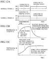
- Figures 12A to 12C show temporal changes in the supply of oxidizer and steam and temporal changes in the temperatures of the catalysts (1) and (2) in the fuel reforming apparatus of the sixth embodiment.
- "ON1" is an oxidizer source connected state
- "ON2" a steam source connected state
- "OFF” a source disconnected state.
- the sixth embodiment integrates the oxidizer feeder (1) 4 and steam feeder(1)7 of the first embodiment into the material feeder (1) 12, and the oxidizer feeder (2) 5 and steam feeder(2)8 of the first embodiment into the material feeder (2) 13.
- the sixth embodiment not only realizes the operation and effect of the first embodiment but also reduces and simplifies the structure of the fuel reforming apparatus.
- the timing of changing the accelerating operation (or a startup operation) to the steady operation is determined according to whether or not the temperature of the catalyst (1) 1 has reached a threshold temperature Tc at which the catalyst (1) 1 stably achieves a steam reforming reaction and partial oxidation reaction.
- the sixth embodiment may employ the temperature sensor 11a and temperature measuring unit 11 of any one of the second to fifth embodiments, to measure the temperature of a specified location and switch the control valves 6 and 9 if the measured temperature has reached a set value.
Abstract
Description
- The present invention relates to a fuel reforming apparatus that simultaneously achieves a steam reforming reaction to produce hydrogen from a hydrocarbon and steam and a partial oxidation reaction to produce hydrogen from a hydrocarbon and an oxidizer and uses heat generated by the partial oxidation reaction that is an exothermic reaction to cover heat for the steam reforming reaction that is an endothermic reaction.
- An example of a methanol reforming apparatus for a fuel cell is disclosed in Japanese Unexamined Patent Publication No. 11-092102. An object of this apparatus is to spatially equalize a temperature distribution in a fuel cell reforming apparatus. The sixth and seventh embodiments of the disclosure temporally change an oxidizer feeding position with respect to a catalyst, to prevent a local temperature increase in the catalyst due to a continuous localized oxidation reaction, promote an internal oxidation reaction, and shorten a startup time.
- This prior art intentionally prevents a localized oxidation reaction, which is an exothermic reaction, and spatially disperses heat produced by the oxidation reaction. Accordingly, the prior art needs a large amount of fuel and time to increase the temperature of a catalyst to an activation level, and therefore, is incapable of shortening a startup time.
- If a part of a catalyst is heated to an activation temperature on startup, the surface of the catalyst starts a chemical reaction to generate heat, which causes a chain reaction of heating the periphery of the heated part of the catalyst, thereby promoting reactions. Therefore, to shorten a startup time, it is necessary to quickly heat, even locally, a catalyst to an activation temperature. The prior art, however, pays no attention to this point.
- An object of the present invention is to provide a fuel reforming apparatus capable of quickly heating a catalyst to an activation temperature and shortening a startup time.
- In order to accomplish the object, a first aspect of the present invention provides a fuel reforming apparatus that supplies, on startup, a hydrocarbon fuel and an oxidizer upstream from a second catalyst and supplies steam upstream from a first catalyst. As a result, the second catalyst starts a rapid oxidation reaction to produce a high-temperature gas, which quickly heats the first catalyst that is downstream of the second catalyst. At the same time, carbon monoxide (CO) produced on the second catalyst reaches the first catalyst and reacts (a shift reaction which is an exothermic reaction) with steam on the first catalyst to promote the heating of the first catalyst. At this time, carbon monoxide produced on the second catalyst is purified into carbon dioxide through a shift reaction on the first catalyst.
- To change the startup operation (or an accelerating operation) to a steady operation after a predetermined period, the apparatus supplies the hydrocarbon fuel and steam upstream from the second catalyst and supplies the oxidizer upstream from the first catalyst. As a result, a steam reforming reaction, which is an endothermic reaction, occurs on the second catalyst, to rapidly cool the second catalyst and stop reactions on the second catalyst. The hydrocarbon fuel and steam passed through the second catalyst without reactions cause a partial oxidation reaction and steam reforming reaction on the first catalyst that is downstream of the second catalyst, to generate a hydrogen-rich reformed gas.
- With these processes, the fuel reforming apparatus of the first aspect shortens a startup time, minimizes the poisoning of a fuel cell arrangeddownstreamof the fuel reforming apparatus, and suppresses the generation of by-products that may deteriorate the quality of emissions.
- A second aspect of the present invention uses a temperature measured around the first catalyst as a parameter to determine whether or not a startup operation or an accelerating operation must be changed to a steady operation. This smoothly changes a startup operation or an accelerating operation to a steady operation while suppressing the generation of by-products.
- A third aspect of the present invention employs an integrated material feeder for each of the first and second catalysts, to feed an oxidizer and steam to the catalysts. This aspect simplifies the structure of the fuel reforming apparatus.
- A fourth aspect of the present invention applies the fuel reforming apparatus of the present invention to a fuel cell system using methanol as a fuel.
- A fifth aspect of the present invention employs an oxidation catalyst, which is commonly available, to improve the durability of the fuel reforming apparatus and reduce the cost thereof.
-
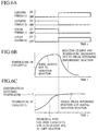
- Figure 1 is a sectional view showing a fuel reforming apparatus according to a first embodiment of the present invention;
- Fig. 2 is a flowchart showing a control operation according to the first embodiment;
- Fig. 3A shows temporal changes in the flows of oxidizer and steam according to the first embodiment;
- Fig. 3B shows temporal changes in the temperature of a catalyst(2) according to the first embodiment;
- Fig. 3C shows temporal changes in the temperature of a catalyst (1) according to the first embodiment;
- Fig. 4 is a sectional view showing a fuel reforming apparatus according to a second embodiment of the present invention;
- Fig. 5 is a flowchart showing a control operation according to the second embodiment;
- Fig. 6A shows temporal changes in the flows of oxidizer and steam according to the second embodiment;
- Fig. 6B shows temporal changes in the temperature of a catalyst(2) according to the second embodiment;
- Fig. 6C shows temporal changes in the temperature of a catalyst (1) according to the second embodiment;
- Fig. 7 is a sectional view showing a fuel reforming apparatus according to a third embodiment of the present invention;
- Fig. 8 is a sectional view showing a fuel reforming apparatus according to a fourth embodiment of the present invention;
- Fig. 9 is a sectional view showing a fuel reforming apparatus according to a fifth embodiment of the present invention;
- Fig. 10 is a sectional view showing a fuel reforming apparatus according to a sixth embodiment of the present invention;
- Fig. 11 is a flowchart showing a control operation according to the sixth embodiment;
- Fig. 12A shows temporal changes in the flows of oxidizer and steam according to the sixth embodiment;
- Fig. 12B shows temporal changes in the temperature of a catalyst(2) according to the sixth embodiment; and
- Fig. 12C shows temporal changes in the temperature of a catalyst (1) according to the sixth embodiment.
-
- Figure 1 is a sectional view showing a fuel reforming apparatus according to the first embodiment of the present invention. A catalyst (1) 1 with a support promotes a steam reforming reaction and a partial oxidation reaction mainly in a steady operation. The catalyst (1) 1 is, for example, a copper-based catalyst or a palladium-based catalyst and is densely arranged without a gap in a downstream area of a
reactor casing 14. A catalyst(2) 2 with a support promotes a partial oxidation reaction mainly in a startup operation or in a transient (accelerating) operation under increasing load. The catalyst(2) 2 is, for example, a copper-based catalyst, a palladium-based catalyst, or an oxidation catalyst and is densely arranged without a gap on the upstream side of the catalyst (1) 1. A fuel feeder 3 receives a hydrocarbon fuel such as methanol from a fuel source (not shown) and sprays or injects the fuel toward the catalyst(2) 2 that is downstream of the fuel feeder 3. The fuel feeder 3 is positioned upstream from the catalyst (2) 2 and is fitted to thecasing 14. - An oxidizer feeder(1) 4 receives an oxidizer from an oxidizer source (not shown) and distributes the oxidizer as uniformly as possible into a gas passage formed between the catalyst (1) 1 and the catalyst (2) 2 in the
casing 14. The oxidizer feeder (1) 4 is fitted to thecasing 14. An oxidizer feeder(2) 5 receives the oxidizer from the oxidizer source (not shown) and distributes the oxidizer as uniformly as possible into a gas passage formed on the upstream side of the catalyst(2) 2 in thecasing 14. The oxidizer feeder(2) 5 is fitted to thecasing 14. Anoxidizer control valve 6 switches the oxidizer supplied from the oxidizer source (not shown) to any one of the oxidizer feeders (1) 4 and (2) 5. Theoxidizer control valve 6 is installed in the middle of piping that connects the oxidizer source to the oxidizer feeders(1) 4 and (2) 5. - A steam feeder(1) 7 receives steam from a steam source (not shown) and distributes the steam as uniformly as possible into the gas passage formed between the catalyst (1) 1 and the catalyst (2) 2 in the
casing 14. The steam feeder(1) 7 is fitted to thecasing 14. A steam feeder(2) 8 receives the steam from the steam source (not shown) and distributes the steam as uniformly as possible into the gas passage formed on the upstream side of the catalyst(2) 2 in thecasing 14. The steam feeder(2) 8 is fitted to thecasing 14. Asteam control valve 9 switches steam supplied from the steam source (not shown) to any one of the steam feeders (1)7 and (2)8. Thesteam control valve 9 is installed in the middle of piping that connects the steam source to the steam feeders (1)7 and (2)8. - A
controller 10 is connected to theoxidizer control valve 6 andsteam control valve 9 through signal lines, to separately control thevalves - A control operation of the fuel reforming apparatus according to the first embodiment will be explained with reference to Fig. 2.
- In response to an external start signal or acceleration signal, the control flow starts.
- Step S10 corresponds to a startup operation or an accelerating operation (transient operation) under increasing load. The
controller 10 sends a switching signal to theoxidizer control valve 6 so as to connect the oxidizer source to the oxidizer feeder(2) 5. At the same time, thecontroller 10 issues a switching signal to thesteam control valve 9 so as to connect the steam source to the steam feeder(1) 7. - As a result, adjusted quantities of hydrocarbon fuel, oxidizer, and steam are supplied to the fuel reforming apparatus. Due to the hydrocarbon fuel and oxidizer supplied from the upstream side, the catalyst (2) 2 starts an oxidation reaction (partial) to rapidly generate heat to increase the temperature of the catalyst (2) 2. This oxidation reaction generates a gas that heats the downstream catalyst (1) 1. Due to carbon monoxide produced by the oxidation reaction on the catalyst(2) 2 and the steam supplied from the upstream side, the catalyst (1) 1 starts a shift reaction to heat the catalyst (1) 1 itself. This shift reaction on the catalyst (1) 1 purifies the carbon monoxide generated by the catalyst(2) 2 into carbon dioxide and hydrogen.
- Step S20 determines whether or not a predetermined time τ has passed under the state of step S10. If the time τ has passed, step S30 is carried out, and if not, the state of step S10 is continued. The time τ is determined to sufficiently bring the temperature of the catalyst(1) 1 to a threshold temperature Tc at which the catalyst (1) 1 stably achieves a steam reforming reaction and partial oxidation reaction.
- In step S30, the
controller 10 issues a switching signal to theoxidizer control valve 6 so as to connect the oxidizer source to the oxidizer feeder(1)4. At the same time, thecontroller 10 provides a switching signal to thesteam control valve 9 so as to connect the steam source to the steam feeder (2) 8. - Due to the hydrocarbon fuel and steam supplied from the upstream side, the catalyst(2) 2 starts a steam reforming reaction, which is an endothermic reaction to decrease the temperature of the catalyst(2) 2 and stop all reactions on the catalyst(2) 2. As a result, the hydrocarbon fuel and steam supplied from the upstream side of the catalyst (2) 2 pass through the catalyst (2) 2 without reactions and reach the catalyst (1) 1. Due to the hydrocarbon fuel and steam passed through the catalyst (2) 2 and the oxidizer supplied from the upstream side, the catalyst (1) 1 promotes a steam reforming reaction and partial oxidation reaction to generate a hydrogen-rich reformed gas. This completes a series of processes.
- Figures 3A to 3C show temporal changes in the supply of oxidizer and steam and temporal changes in the temperatures of the catalysts (1) and (2) in the fuel reforming apparatus of the first embodiment. In Fig. 3A, "ON" is an oxidizer or steam source connected state and "OFF" a source disconnected state. The fuel reforming apparatus of the first embodiment quickly promotes an oxidation reaction (partial) on the catalyst (2) to speedily heat the catalyst (1). Generated carbon monoxide reacts with steam on the catalyst(1) to start a shift reaction. Consequently, the first embodiment reduces a startup time, minimizes the poisoning of a fuel cell arranged on the downstream side of the fuel reforming apparatus, and suppresses the generation of by-products that deteriorate the quality of emissions.
- Figure 4 is a sectional view showing a fuel reforming apparatus according to the second embodiment of the present invention. The structure of the second embodiment is basically the same as that of the first embodiment and differs therefrom in that a
temperature measuring unit 11 is connected to acontroller 10 and atemperature sensor 11a is fitted to areactor casing 14 in the vicinity of a catalyst (1) 1, to measure a temperature around the catalyst (1) 1. Data measured by thetemperature measuring unit 11 is sent to thecontroller 10. - A control operation of the fuel reforming apparatus of the second embodiment will be explained with reference to Fig. 5. The control operation of the second embodiment is basically the same as that of the first embodiment of Fig. 2, and therefore, only the difference of the second embodiment from the first embodiment will be explained.
- Step S20' uses a signal from the
temperature measuring unit 11 to determine whether or not a temperature around the catalyst (1) 1 has reached to a predetermined temperature T. If it has reached the value T, step S30 is carried out, and if not, the state of step S10 is maintained. The temperature T is based on a threshold temperature Tc at which the catalyst (1) 1 stably achieves a steam reforming reaction and partial oxidation reaction. During an accelerating operation, the temperature of the catalyst(1) 1 transiently changes, and therefore, it is possible to estimate the temperature of the catalyst(1) 1 according to temporal changes in temperatures around the catalyst(1) 1, to correctly determine the timing of switching to a steady operation. It is also possible to check the threshold temperature Tc based on temperature data measured at different locations, which will be explained later. - Figures 6A to 6C show temporal changes in the supply of oxidizer and steam and temporal changes in the temperatures of the catalysts (1) and (2) in the fuel reforming apparatus of the second embodiment. In Fig. 6A, a status being connected to a corresponding material source is depicted as "ON", and disconnected thereto as "OFF". The fuel reforming apparatus of the second embodiment uses a temperature measured in the vicinity of the catalyst(1) as a parameter to determine whether or not a steady operation must be started. In addition to the effect of the first embodiment, the second embodiment further shortens a startup time and smoothly changes a startup operation or an accelerating operation to a steady operation while suppressing the generation of by-products.
- Figure 7 is a sectional view showing a fuel reforming apparatus according to the third embodiment of the present invention. The structure of the third embodiment is basically the same as that of the second embodiment of Fig. 4 and differs therefrom in that a
temperature sensor 11a is fitted to areactor casing 14 at a position in a gas passage defined in thecasing 14 on the upstream side of a catalyst(1) 1, to detect a gas temperature on the upstream side of the catalyst (1) 1. Thetemperature sensor 11a is connected to atemperature measuring unit 11, which sends temperature data to acontroller 10. - A control operation of the third embodiment is basically the same as that of the second embodiment. In addition to the operation and effect of the second embodiment, the third embodiment directly measures the temperature of a gas sent from a catalyst(2) 2, to speedily determine the timing of changing a startup operation or an accelerating operation to a steady operation, thereby further reducing a startup time.
- Figure 8 is a sectional view showing a fuel reforming apparatus according to the fourth embodiment of the present invention. The structure of the fourth embodiment is basically the same as that of the second embodiment of Fig. 4 and differs therefrom in that a
temperature sensor 11a is inserted into a catalyst (1) 1 and is fitted to areactor casing 14, to detect an inside temperature of the catalyst(1) 1. Thetemperature sensor 11a is connected to atemperature measuring unit 11, which sends temperature data to acontroller 10. - A control operation of the fourth embodiment is basically the same as that of the second embodiment. In addition to the operation and effect of the second embodiment, the fourth embodiment directly detects an internal temperature of the catalyst(1) 1, to surely change a startup operation or an accelerating operating to a steady operation without extinction.
- Figure 9 is a sectional view showing a fuel reforming apparatus according to the fifth embodiment of the present invention. The structure of the fifth embodiment is basically the same as that of the second embodiment of Fig. 4 and differs therefrom in that a
temperature sensor 11a is fitted to areactor casing 14 at a position in a gas passage defined in thecasing 14 on the downstream side of a catalyst(1) 1, to detect a gas temperature on the downstream side of the catalyst(1) 1. Thetemperature sensor 11a is connected to atemperature measuring unit 11, which sends temperature data to acontroller 10. - A control operation of the fifth embodiment is basically the same as that of the second embodiment. In addition to the operation and effect of the second embodiment, the fifth embodiment measures a gas temperature on the downstream side of the catalyst (1) 1. Since the downstream side temperature is relatively low, the
temperature sensor 11a andtemperature measuring unit 11 of the fifth embodiment may extend durability and inexpensive to reduce costs. - Figure 10 is a sectional view showing a fuel reforming apparatus according to the sixth embodiment of the present invention. The structure of the sixth embodiment is basically the same as that of the first embodiment of Fig. 1 and differs therefrom in that the sixth embodiment employs a material feeder (1) 12 and a material feeder (2) 13. The material feeder (1) 12 is fitted to a
reactor casing 14, to receive an oxidizer from an oxidizer source (not shown), or steam from a steam source (not shown) and distribute the received material as uniformly as possible into a passage defined in thecasing 14 between a catalyst (1) 1 and a catalyst(2) 2. The material feeder(2) 13 is fitted to thecasing 14, to receive one of the oxidizer from the oxidizer source and the steam from the steam source and distribute the received material as uniformly as possible into a passage defined in thecasing 14 on the upstream side of the catalyst(2) 2. - A control operation of the fuel reforming apparatus of the sixth embodiment will be explained with reference to Fig. 11. This operation is basically the same as that of the first embodiment of Fig. 2, and therefore, only the difference of the sixth embodiment from the first embodiment will be explained.
- In step S10, a
controller 10 issues a signal to anoxidizer control valve 6 to connect the oxidizer source to the material feeder (2) 13. At the same time, thecontroller 10 issues a signal so as to asteam control valve 9 to connect the steam source to the material feeder(1) 12. As a result, adjusted quantities of hydrocarbon fuel, oxidizer, and steam are supplied to the fuel reforming apparatus. Due to the hydrocarbon fuel and oxidizer supplied from the upstream side, the catalyst (2) 2 starts an oxidation reaction (partial) to rapidly generate heat to increase the temperature of the catalyst(2) 2. This oxidation reaction produces a gas that heats the downstream catalyst (1) 1. At the same time, due to carbon monoxide produced by the oxidation reaction on the catalyst (2) 2 and the steam supplied from the upstream side, the catalyst (1) 1 starts a shift reaction to heat the catalyst (1) 1 itself. This shift reaction on the catalyst(1) 1 purifies the carbon monoxide generated by the catalyst(2) 2 into carbon dioxide and hydrogen. - Step S20 determines whether or not a predetermined time τ has passed under the state of step S10. If the time τ has passed, step S30 is carried out, and if not, the state of step S10 is continued.
- In step S30, the
controller 10 issues a signal to theoxidizer control valve 6 to connect the oxidizer source to the material feeder (1) 12. At the same time, thecontroller 10 issues a signal to thesteam control valve 9 so as to connect the steam source to the material feeder(2)13. Due to the hydrocarbon fuel and steam supplied from the upstream side, the catalyst (2) 2 starts a steam reforming reaction, which is an endothermic reaction to decrease the temperature of the catalyst(2) 2 and stop all reactions on the catalyst(2) 2. As a result, the hydrocarbon fuel and steam supplied from the upstream side of the catalyst (2) 2 pass through the catalyst(2) 2 without reactions and reach the catalyst (1) 1. - Due to the hydrocarbon fuel and steam passed through the catalyst (2) 2 and the oxidizer supplied from the upstream side, the catalyst (1) 1 promotes a steam reforming reaction and partial oxidation reaction to generate a hydrogen-rich reformed gas. This completes a series of processes.
- Figures 12A to 12C show temporal changes in the supply of oxidizer and steam and temporal changes in the temperatures of the catalysts (1) and (2) in the fuel reforming apparatus of the sixth embodiment. In Fig. 12A, "ON1" is an oxidizer source connected state, "ON2" a steam source connected state, and "OFF" a source disconnected state. In this way, the sixth embodiment integrates the oxidizer feeder (1) 4 and steam feeder(1)7 of the first embodiment into the material feeder (1) 12, and the oxidizer feeder (2) 5 and steam feeder(2)8 of the first embodiment into the material feeder (2) 13. As a result, the sixth embodiment not only realizes the operation and effect of the first embodiment but also reduces and simplifies the structure of the fuel reforming apparatus.
- The timing of changing the accelerating operation (or a startup operation) to the steady operation is determined according to whether or not the temperature of the catalyst (1) 1 has reached a threshold temperature Tc at which the catalyst (1) 1 stably achieves a steam reforming reaction and partial oxidation reaction. Instead of the configuration that checks the predetermined time τ to switch the
oxidizer control valve 6 andsteam control valve 9, the sixth embodiment may employ thetemperature sensor 11a andtemperature measuring unit 11 of any one of the second to fifth embodiments, to measure the temperature of a specified location and switch thecontrol valves
Claims (10)
- A fuel reforming apparatus for simultaneously achieving a steam reforming reaction that produces hydrogen from a hydrocarbon and steam and a partial oxidation reaction that produces hydrogen from the hydrocarbon and an oxidizer and using heat generated by the partial oxidation reaction that is an exothermic reaction to cover heat for the steam reforming reaction that is an endothermic reaction, comprising:a first catalyst with a support, for promoting the steam reforming reaction and partial oxidation reaction;a second catalyst with a support positioned upstream from the first catalyst, for promoting the partial oxidation reaction;fuel feeding means for feeding the hydrocarbon as a fuel upstream from the second catalyst;first oxidizer feeding means for feeding the oxidizer to the first catalyst;second oxidizer feeding means for feeding the oxidizer to the second catalyst;oxidizer controlling means for selectively supplying the oxidizer from an oxidizer source to one of the first and second oxidizer feeding means;first steam feeding means for feeding steam to the first catalyst;second steam feeding means for feeding steam to the second catalyst;steam controlling means for selectively supplying steam from a steam source to one of the first and second steam feeding means; andmaster controlling means for controlling the oxidizer controlling means and steam controlling means, wherein:the master controlling means has first and second states, to control the oxidizer controlling means and steam controlling means in such a manner as to connect, in the first state, the oxidizer source to the second oxidizer feeding means and the steam source to the first steam feeding means, and in the second state, the oxidizer source to the first oxidizer feeding means and the steam source to the second steam feeding means; andthe master controlling means is in the first state during startup and transient operations and is in the second state during the other operations.
- The apparatus of claim 1, wherein the master controlling means is switched to the second state after it is maintained in the first state for a predetermined period.
- The apparatus of claim 1, further comprising:temperature measuring means for measuring a temperature of the first catalyst and sending an output to the master controlling means, wherein:the master controlling means is switched from the first state to the second state if the output from the temperature measuring means is equal to a predetermined value.
- A fuel reforming apparatus for simultaneously achieving a steam reforming reaction that produces hydrogen from a hydrocarbon and steam and a partial oxidation reaction that produces hydrogen from the hydrocarbon and an oxidizer and using heat generated by the partial oxidation reaction that is an exothermic reaction to cover heat for the steam reforming reaction that is an endothermic reaction, comprising:a first catalyst with a support, for promoting the steam reforming reaction and partial oxidation reaction;a second catalyst with a support positioned upstream from the first catalyst, for promoting the partial oxidation reaction;fuel feeding means for feeding the hydrocarbon as a fuel upstream from the second catalyst;first material feeding means for feeding one of the oxidizer and steam to the first catalyst;second material feeding means for feeding one of the oxidizer and steam to the second catalyst;oxidizer controlling means for selectively supplying the oxidizer from an oxidizer source to one of the first and second material feeding means;steam controlling means for selectively supplying steam from a steam source to one of the first and second material feeding means; andmaster controlling means for controlling the oxidizer controlling means and steam controlling means, wherein:the master controlling means has first and second states, to control the oxidizer controlling means and steam controlling means in such a manner as to connect, in the first state, the oxidizer source to the second material feeding means and the steam source to the first material feeding means, and in the second state, the oxidizer source to the first material feeding means and the steam source to the second material feeding means; andthe master controlling means is in the first state during startup and transient operations and is in the second state during the other operations.
- The apparatus of claim 4, further comprising:temperature measuring means for measuring a temperature of the first catalyst and sending an output to the master controlling means, whereinthe master controlling means is switched from the first state to the second state if the output from the temperature measuring means is equal to a predetermined value.
- The apparatus of any one of claims 3 and 5, wherein the temperature measuring means at least measures the temperature of a predetermined location in a gas passage on the inlet side of the first catalyst.
- The apparatus of any one of claims 3 and 5, wherein the temperature measuring means at least measures the temperature of an inside location of the first catalyst.
- The apparatus of any one of claims 3 and 5, wherein the temperature measuring means at least measures the temperature of a predetermined location in a gas passage on the outlet side of the first catalyst.
- The apparatus of any one of claims 1 and 4, wherein the hydrocarbon is methanol; and each of the first and second catalysts is one of a copper-based catalyst and a palladium-based catalyst.
- The apparatus of any one of claims 1 and 4, wherein the hydrocarbon is methanol; and
the first catalyst is one of a copper-based catalyst and a palladium-based catalyst; and
the second catalyst is an oxidation catalyst.
Applications Claiming Priority (2)
| Application Number | Priority Date | Filing Date | Title |
|---|---|---|---|
| JP2000165098A JP3646625B2 (en) | 2000-06-01 | 2000-06-01 | Fuel reformer |
| JP2000165098 | 2000-06-01 |
Publications (1)
| Publication Number | Publication Date |
|---|---|
| EP1160193A1 true EP1160193A1 (en) | 2001-12-05 |
Family
ID=18668625
Family Applications (1)
| Application Number | Title | Priority Date | Filing Date |
|---|---|---|---|
| EP01113313A Withdrawn EP1160193A1 (en) | 2000-06-01 | 2001-05-31 | Reforming apparatus |
Country Status (3)
| Country | Link |
|---|---|
| US (1) | US6767518B2 (en) |
| EP (1) | EP1160193A1 (en) |
| JP (1) | JP3646625B2 (en) |
Cited By (9)
| Publication number | Priority date | Publication date | Assignee | Title |
|---|---|---|---|---|
| WO2003042097A1 (en) * | 2001-11-16 | 2003-05-22 | Nissan Motor Co., Ltd. | Fuel reforming system and control therefor |
| FR2847489A1 (en) * | 2002-11-25 | 2004-05-28 | Bosch Gmbh Robert | Integrated reactor with two separated channel structures carrying two fluids, one taking part in a reaction generating heat and with heat transfer between the two at the same time, notably for fuel systems |
| WO2005029616A2 (en) * | 2003-09-24 | 2005-03-31 | Nissan Motor Co., Ltd. | Fuel reforming system |
| EP1611625A2 (en) * | 2003-04-04 | 2006-01-04 | Texaco Development Corporation | Architectural hierarchy of control for a fuel processor |
| WO2006008138A1 (en) * | 2004-07-19 | 2006-01-26 | Ab Volvo | Method and arrangement for reforming fuel |
| EP1785394A2 (en) | 2005-11-10 | 2007-05-16 | Samsung SDI Co., Ltd. | Reformer and Method of Operating a Reformer |
| WO2008001119A2 (en) * | 2006-06-29 | 2008-01-03 | Ceres Intellectual Property Company Limited | Steam reforming method for fuel cells |
| US7381230B2 (en) | 2004-12-30 | 2008-06-03 | Conocophillips Company | Reactor and process for making synthesis gas |
| EP2022756A2 (en) * | 2007-08-07 | 2009-02-11 | Delphi Technologies, Inc. | Staged Hydrocarbon Reformer |
Families Citing this family (17)
| Publication number | Priority date | Publication date | Assignee | Title |
|---|---|---|---|---|
| JP4923360B2 (en) * | 2001-09-04 | 2012-04-25 | トヨタ自動車株式会社 | Fuel reformer equipped with steam mixing device having thin plate laminated structure, steam mixing device, and method of manufacturing steam mixing device |
| US7810317B2 (en) * | 2002-03-27 | 2010-10-12 | Precision Combustion, Inc. | Catalytic burner utilizing electrosprayed fuels |
| JP4147521B2 (en) * | 2002-05-17 | 2008-09-10 | 株式会社日本ケミカル・プラント・コンサルタント | Self-oxidation internal heating type reforming method and apparatus |
| DE10253930A1 (en) * | 2002-11-19 | 2004-06-09 | Umicore Ag & Co.Kg | Process for producing a hydrogen-containing fuel gas for fuel cells and device therefor |
| US8795398B2 (en) | 2003-07-31 | 2014-08-05 | Precision Combustion, Inc. | Apparatus for vaporizing and reforming liquid fuels |
| US7976594B2 (en) | 2003-07-31 | 2011-07-12 | Precision Combustion, Inc. | Method and system for vaporization of liquid fuels |
| JP2007117798A (en) * | 2005-10-25 | 2007-05-17 | Ishikawajima Harima Heavy Ind Co Ltd | Reforming catalyst, reforming method, operation method and structure of reforming catalyst |
| US20070151154A1 (en) * | 2005-11-04 | 2007-07-05 | Maxim Lyubovsky | Catalytic system for converting liquid fuels into syngas |
| US8444951B2 (en) * | 2005-11-04 | 2013-05-21 | Precision Combustion, Inc. | Catalytic process and system for converting liquid fuels into syngas |
| US8557189B2 (en) * | 2005-11-04 | 2013-10-15 | Precision Combustion, Inc. | Catalytic system for converting liquid fuels into syngas |
| US7913484B2 (en) * | 2006-02-28 | 2011-03-29 | Precision Combustion, Inc. | Catalytic burner apparatus for stirling engine |
| US8387380B2 (en) * | 2006-02-28 | 2013-03-05 | Precision Combustion, Inc. | Catalytic burner apparatus for Stirling Engine |
| US8479508B2 (en) * | 2006-02-28 | 2013-07-09 | Precision Combustion, Inc. | Catalytic burner apparatus for stirling engine |
| CA2698238C (en) * | 2007-10-22 | 2014-04-01 | Osum Oil Sands Corp. | Method of removing carbon dioxide emissions from in-situ recovery of bitumen and heavy oil |
| US8176982B2 (en) | 2008-02-06 | 2012-05-15 | Osum Oil Sands Corp. | Method of controlling a recovery and upgrading operation in a reservoir |
| CA2718885C (en) * | 2008-05-20 | 2014-05-06 | Osum Oil Sands Corp. | Method of managing carbon reduction for hydrocarbon producers |
| US8591844B1 (en) | 2012-05-17 | 2013-11-26 | Fluor Technologies Corporation | Start up catalyst heating |
Citations (5)
| Publication number | Priority date | Publication date | Assignee | Title |
|---|---|---|---|---|
| US4789540A (en) * | 1985-09-03 | 1988-12-06 | Johnson Matthey Public Limited Co. | Catalytic hydrogen generator for use with methanol |
| JPH06305702A (en) * | 1993-04-22 | 1994-11-01 | Mitsubishi Gas Chem Co Inc | Method for starting gas reformer |
| EP0921585A2 (en) * | 1997-12-05 | 1999-06-09 | dbb fuel cell engines GmbH | Device and method for steam reforming of hydrocarbons |
| WO1999031012A1 (en) * | 1997-12-16 | 1999-06-24 | Dbb Fuel Cell Engines Gesellschaft Mit Beschränkter Haftung | Method for operating a system for water-vapor reforming of a hydrocarbon |
| JP2000042412A (en) * | 1998-07-29 | 2000-02-15 | Toyota Motor Corp | Fuel reforming catalyst |
Family Cites Families (10)
| Publication number | Priority date | Publication date | Assignee | Title |
|---|---|---|---|---|
| US4861347A (en) * | 1986-12-29 | 1989-08-29 | International Fuel Cells Corporation | Compact chemical reaction vessel |
| AU3277097A (en) * | 1996-06-28 | 1998-01-21 | Matsushita Electric Works Ltd. | Modification apparatus |
| JP4305973B2 (en) | 1997-07-23 | 2009-07-29 | トヨタ自動車株式会社 | Fuel reformer |
| JP2000203804A (en) * | 1999-01-14 | 2000-07-25 | Toyota Motor Corp | Fuel reformer and reforming of fuel |
| US6190623B1 (en) * | 1999-06-18 | 2001-02-20 | Uop Llc | Apparatus for providing a pure hydrogen stream for use with fuel cells |
| KR20020074464A (en) * | 1999-12-28 | 2002-09-30 | 마쯔시다덴기산교 가부시키가이샤 | Apparatus for forming hydrogen |
| US6869456B2 (en) * | 2000-06-27 | 2005-03-22 | Delphi Technologies, Inc. | Method for starting a fast light-off catalytic fuel reformer |
| DE10148620B4 (en) * | 2000-10-06 | 2009-04-23 | Denso Corp., Kariya-shi | Hydrogen supply device |
| US7037349B2 (en) * | 2002-06-24 | 2006-05-02 | Delphi Technologies, Inc. | Method and apparatus for fuel/air preparation in a fuel cell |
| DE10231883B4 (en) * | 2002-07-12 | 2008-01-17 | J. Eberspächer GmbH & Co. KG | Evaporator arrangement, in particular for producing a hydrocarbon / mixed material mixture decomposable in a hydrogen recovery reformer |
-
2000
- 2000-06-01 JP JP2000165098A patent/JP3646625B2/en not_active Expired - Fee Related
-
2001
- 2001-05-25 US US09/864,230 patent/US6767518B2/en not_active Expired - Fee Related
- 2001-05-31 EP EP01113313A patent/EP1160193A1/en not_active Withdrawn
Patent Citations (5)
| Publication number | Priority date | Publication date | Assignee | Title |
|---|---|---|---|---|
| US4789540A (en) * | 1985-09-03 | 1988-12-06 | Johnson Matthey Public Limited Co. | Catalytic hydrogen generator for use with methanol |
| JPH06305702A (en) * | 1993-04-22 | 1994-11-01 | Mitsubishi Gas Chem Co Inc | Method for starting gas reformer |
| EP0921585A2 (en) * | 1997-12-05 | 1999-06-09 | dbb fuel cell engines GmbH | Device and method for steam reforming of hydrocarbons |
| WO1999031012A1 (en) * | 1997-12-16 | 1999-06-24 | Dbb Fuel Cell Engines Gesellschaft Mit Beschränkter Haftung | Method for operating a system for water-vapor reforming of a hydrocarbon |
| JP2000042412A (en) * | 1998-07-29 | 2000-02-15 | Toyota Motor Corp | Fuel reforming catalyst |
Non-Patent Citations (2)
| Title |
|---|
| PATENT ABSTRACTS OF JAPAN vol. 1995, no. 02 31 March 1995 (1995-03-31) * |
| PATENT ABSTRACTS OF JAPAN vol. 2000, no. 05 14 September 2000 (2000-09-14) * |
Cited By (22)
| Publication number | Priority date | Publication date | Assignee | Title |
|---|---|---|---|---|
| US7101531B2 (en) | 2001-11-16 | 2006-09-05 | Nissan Motor Co., Ltd. | Fuel reforming system and control therefor |
| WO2003042097A1 (en) * | 2001-11-16 | 2003-05-22 | Nissan Motor Co., Ltd. | Fuel reforming system and control therefor |
| FR2847489A1 (en) * | 2002-11-25 | 2004-05-28 | Bosch Gmbh Robert | Integrated reactor with two separated channel structures carrying two fluids, one taking part in a reaction generating heat and with heat transfer between the two at the same time, notably for fuel systems |
| AU2004227337B2 (en) * | 2003-04-04 | 2011-01-06 | Texaco Development Corporation | Architectural hierarchy of control for a fuel processor |
| EP1611625A4 (en) * | 2003-04-04 | 2008-03-26 | Texaco Development Corp | Architectural hierarchy of control for a fuel processor |
| US7785539B2 (en) | 2003-04-04 | 2010-08-31 | Texaco Inc. | Method of controlling a hydrogen generator |
| EP1611625A2 (en) * | 2003-04-04 | 2006-01-04 | Texaco Development Corporation | Architectural hierarchy of control for a fuel processor |
| US7593788B2 (en) | 2003-04-04 | 2009-09-22 | Texaco Inc. | Automated control strategy for fuel processor reactor shift catalyst regeneration |
| US8260464B2 (en) | 2003-04-04 | 2012-09-04 | Texaco Inc. | Architectural hierarchy of control for a fuel processor |
| US7547333B2 (en) | 2003-09-24 | 2009-06-16 | Nissan Motor Co., Ltd. | Fuel reforming system |
| WO2005029616A2 (en) * | 2003-09-24 | 2005-03-31 | Nissan Motor Co., Ltd. | Fuel reforming system |
| WO2005029616A3 (en) * | 2003-09-24 | 2006-08-17 | Nissan Motor | Fuel reforming system |
| US7828863B2 (en) | 2004-07-19 | 2010-11-09 | Ab Volvo | Method and arrangement for reforming fuel |
| WO2006008138A1 (en) * | 2004-07-19 | 2006-01-26 | Ab Volvo | Method and arrangement for reforming fuel |
| US7381230B2 (en) | 2004-12-30 | 2008-06-03 | Conocophillips Company | Reactor and process for making synthesis gas |
| EP1785394A2 (en) | 2005-11-10 | 2007-05-16 | Samsung SDI Co., Ltd. | Reformer and Method of Operating a Reformer |
| US7838161B2 (en) | 2005-11-10 | 2010-11-23 | Samsung Sdi Co., Ltd. | Reformer and fuel cell system using the same |
| EP1785394A3 (en) * | 2005-11-10 | 2009-12-30 | Samsung SDI Co., Ltd. | Reformer and Method of Operating a Reformer |
| WO2008001119A3 (en) * | 2006-06-29 | 2008-05-22 | Ceres Ip Co Ltd | Steam reforming method for fuel cells |
| WO2008001119A2 (en) * | 2006-06-29 | 2008-01-03 | Ceres Intellectual Property Company Limited | Steam reforming method for fuel cells |
| EP2022756A3 (en) * | 2007-08-07 | 2009-12-02 | Delphi Technologies, Inc. | Staged Hydrocarbon Reformer |
| EP2022756A2 (en) * | 2007-08-07 | 2009-02-11 | Delphi Technologies, Inc. | Staged Hydrocarbon Reformer |
Also Published As
| Publication number | Publication date |
|---|---|
| US20010047620A1 (en) | 2001-12-06 |
| JP3646625B2 (en) | 2005-05-11 |
| JP2001348206A (en) | 2001-12-18 |
| US6767518B2 (en) | 2004-07-27 |
Similar Documents
| Publication | Publication Date | Title |
|---|---|---|
| US6767518B2 (en) | Reforming apparatus | |
| JP3885479B2 (en) | Fuel cell reformer | |
| US7147946B2 (en) | Fuel cell system | |
| KR100865919B1 (en) | Method for regenerating a reformer | |
| EP1557395B1 (en) | Hydrogen generator and fuel cell system | |
| US20100221619A1 (en) | Fuel cell system | |
| US6702991B1 (en) | Apparatus and method for reducing power consumption of a plasma fuel reformer | |
| AU2006281775B2 (en) | Fuel cell system and method for the operation of a reformer | |
| WO2003027006A3 (en) | Fuel reforming system | |
| JP3642270B2 (en) | Fuel reformer | |
| US7261750B1 (en) | Method for the autothermal reforming of a hydrocarbon | |
| JP2005174745A5 (en) | ||
| JP4030322B2 (en) | Fuel processing apparatus, fuel cell power generation system, fuel processing method, and fuel cell power generation method | |
| KR100759693B1 (en) | Carbon monoxide remover and reformer for fuel cell | |
| US20040052693A1 (en) | Apparatus and method for removing NOx from the exhaust gas of an internal combustion engine | |
| JP2006169068A5 (en) | ||
| JP4534277B2 (en) | Reformer | |
| US20040081593A1 (en) | Reactor system for hydrogen production | |
| EP2474502B1 (en) | Hydrogen generator and method for starting same | |
| US20040011703A1 (en) | Warm-up device for catalytic reactor | |
| JP4975958B2 (en) | Burner for a reformer in a fuel cell system | |
| JP2001023675A (en) | Water gas shift reactor warm-up | |
| JP3664003B2 (en) | Reformer | |
| JP2004256356A (en) | Method of manufacturing reformed gas and reforming apparatus used for the manufacturing method | |
| JP2005050563A (en) | Fuel reforming system |
Legal Events
| Date | Code | Title | Description |
|---|---|---|---|
| PUAI | Public reference made under article 153(3) epc to a published international application that has entered the european phase |
Free format text: ORIGINAL CODE: 0009012 |
|
| 17P | Request for examination filed |
Effective date: 20010531 |
|
| AK | Designated contracting states |
Kind code of ref document: A1 Designated state(s): DE FR GB Kind code of ref document: A1 Designated state(s): AT BE CH CY DE DK ES FI FR GB GR IE IT LI LU MC NL PT SE TR |
|
| AX | Request for extension of the european patent |
Free format text: AL;LT;LV;MK;RO;SI |
|
| AKX | Designation fees paid |
Free format text: DE FR GB |
|
| 17Q | First examination report despatched |
Effective date: 20050411 |
|
| GRAP | Despatch of communication of intention to grant a patent |
Free format text: ORIGINAL CODE: EPIDOSNIGR1 |
|
| STAA | Information on the status of an ep patent application or granted ep patent |
Free format text: STATUS: THE APPLICATION IS DEEMED TO BE WITHDRAWN |
|
| 18D | Application deemed to be withdrawn |
Effective date: 20101201 |