EP1162540A1 - Method and apparatus for synchronizing a system with coupled data processing units - Google Patents
Method and apparatus for synchronizing a system with coupled data processing units Download PDFInfo
- Publication number
- EP1162540A1 EP1162540A1 EP00112203A EP00112203A EP1162540A1 EP 1162540 A1 EP1162540 A1 EP 1162540A1 EP 00112203 A EP00112203 A EP 00112203A EP 00112203 A EP00112203 A EP 00112203A EP 1162540 A1 EP1162540 A1 EP 1162540A1
- Authority
- EP
- European Patent Office
- Prior art keywords
- data processing
- synchronization
- data
- clock
- tick
- Prior art date
- Legal status (The legal status is an assumption and is not a legal conclusion. Google has not performed a legal analysis and makes no representation as to the accuracy of the status listed.)
- Withdrawn
Links
- 238000000034 method Methods 0.000 title claims abstract description 43
- 238000012545 processing Methods 0.000 title claims abstract description 39
- 230000005540 biological transmission Effects 0.000 claims abstract description 5
- 230000008569 process Effects 0.000 claims description 22
- 230000006870 function Effects 0.000 claims description 9
- 238000004891 communication Methods 0.000 claims description 3
- 238000005516 engineering process Methods 0.000 claims 1
- 230000036962 time dependent Effects 0.000 claims 1
- 101100028477 Drosophila melanogaster Pak gene Proteins 0.000 description 4
- 230000001360 synchronised effect Effects 0.000 description 3
- 238000012546 transfer Methods 0.000 description 3
- 101000821096 Homo sapiens Synapsin-2 Proteins 0.000 description 2
- 102100021994 Synapsin-2 Human genes 0.000 description 2
- 230000008901 benefit Effects 0.000 description 2
- 239000013256 coordination polymer Substances 0.000 description 2
- 238000001514 detection method Methods 0.000 description 2
- 238000011161 development Methods 0.000 description 2
- 230000001960 triggered effect Effects 0.000 description 2
- 101000821100 Homo sapiens Synapsin-1 Proteins 0.000 description 1
- 102100021905 Synapsin-1 Human genes 0.000 description 1
- 238000007792 addition Methods 0.000 description 1
- 238000013459 approach Methods 0.000 description 1
- 230000008859 change Effects 0.000 description 1
- 238000012937 correction Methods 0.000 description 1
- 238000010586 diagram Methods 0.000 description 1
- 238000012423 maintenance Methods 0.000 description 1
- 230000007246 mechanism Effects 0.000 description 1
- 238000012544 monitoring process Methods 0.000 description 1
- 230000000737 periodic effect Effects 0.000 description 1
- 230000004044 response Effects 0.000 description 1
- 238000012552 review Methods 0.000 description 1
- 238000000926 separation method Methods 0.000 description 1
- 238000013024 troubleshooting Methods 0.000 description 1
Images


Classifications
-
- G—PHYSICS
- G06—COMPUTING; CALCULATING OR COUNTING
- G06F—ELECTRIC DIGITAL DATA PROCESSING
- G06F11/00—Error detection; Error correction; Monitoring
- G06F11/07—Responding to the occurrence of a fault, e.g. fault tolerance
- G06F11/16—Error detection or correction of the data by redundancy in hardware
- G06F11/1675—Temporal synchronisation or re-synchronisation of redundant processing components
- G06F11/1679—Temporal synchronisation or re-synchronisation of redundant processing components at clock signal level
-
- G—PHYSICS
- G06—COMPUTING; CALCULATING OR COUNTING
- G06F—ELECTRIC DIGITAL DATA PROCESSING
- G06F11/00—Error detection; Error correction; Monitoring
- G06F11/07—Responding to the occurrence of a fault, e.g. fault tolerance
- G06F11/16—Error detection or correction of the data by redundancy in hardware
- G06F11/1675—Temporal synchronisation or re-synchronisation of redundant processing components
- G06F11/1683—Temporal synchronisation or re-synchronisation of redundant processing components at instruction level
Definitions
- the present invention relates to a device and a Method according to the preamble of patent claim 1 or 3rd
- Multi-computer systems can use so-called diversified hardware be executed.
- a multi-computer system is then based on diversified hardware if individual components like especially processors in different architecture executed and mostly produced by different manufacturers are.
- diverse hardware errors can also be identified, that are inherent to a particular computer or processor.
- unitary hardware is increasingly being used characterized by a uniform hardware structure.
- Typical multi-computer systems are under the terms 2v2 and 2v3 and other configurations known.
- a 2v2 system there are two data processing systems coupled with each other through an interface.
- periodic comparison of status data of the both data processing systems only have one Further processing of process data, if this Comparison of both data processing systems per equality have determined in the event of an inequality error handling takes place. All or at least safety-relevant commands are not in the event of inequality executed and the system to be controlled is saved in a safe Brought condition.
- the present invention is therefore based on the object to provide an apparatus and a method which enable security applications realize where a clear simple separation of actual application and synchronization is possible.
- the system according to the invention is used in multi-computer systems, for example 2v2 or 2v3 systems only one active hardware timer (master clock) is required the resulting risks are mutual Hardware timer synchronization disabled.
- master clock In order to a coupled computer also has a clock this through the process of time synchronization replicated. Since every computer with a hardware timer is equipped, which one is determined at system start Computer has the so-called master clock. This Allocation can be changed during operation if required.
- the device according to the invention and the invention The procedure is generally for all types of multi-computer systems applicable.
- the method according to the invention sees a standardized Data interface for the mutual data exchange of the Data processing systems.
- By standardizing the Interface in connection with the definition of Synchronization points can be the data to be checked the right processing steps simply and safely be assigned to. This has the advantage that too Data processing systems with multitasking systems without further system additions and without any restrictions can apply methods according to the invention.
- Data for the check parameterizable that is, the telegram length can Needs are adjusted so that in extreme cases none Data are passed or on the other hand a lot of data. This helps to optimize the Synchronization time at.
- the data is on can be parameterized in order to be able to carry out a voting or to better compare analog values.
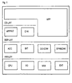
- Figure 1 shows a typical structure of a system architecture with the four layers of hardware HW-LAY, driver BSP-LAY, Operating system OS-LAY and application APP.
- This structure allows the processes to be separated from the Hardware. It can be seen that applications with APP time-critical functions directly, without detours via the Operate the OS-LAY operating system.
- the multi-computer communication units 2/3-COM and Synchronization & backup SYN & CHK in the driver layer classified. That means that the APP application is already from the Architecture is separated from the SYN & CHK synchronization.
- the synchronization unit SYN & CHK and the communication unit 2/3-COM is preferably used as an autonomous Driver function trained so that these units Being able to work independently and by everyone Applications APP and OS-LAY operating system can be used are.
- the driver units work together with the hardware and are therefore adapted to the computer. Not all of them Driver functions of the hardware must be adapted also driver functions use other driver functions, so that for many driver functions again generally applicable Approaches can be found.
- Synchronization takes place in two stages. On the one hand OS-LAY operating systems are synchronized, on the other hand data (application data) is synchronized.
- Figure 2 shows the structure of a time synchronization according to the invention of the system. With this time synchronization that time for the computer to become an external Dimension becomes. The time units begin and end all computers almost simultaneously. A synchronization under the computers can be done via serial connections.
- One of the computers designated R1 in FIG. 2, is called a kind of master, he has an active one Hardware timer HW.
- the process is not a master-slave process.
- the calculator R1 only serves to define the Order among the computers to complete the procedure simplify and clarify boundary conditions. At Error detection is absolutely equivalent to computers Boundary conditions more difficult to understand.
- the master computer can change, for example, if the original master was switched off.
- Time synchronization is started on computer R1 by an active hardware timer HW.
- a clock pulse of this hardware timer HW is called a tick.
- a telegram 1.1 resp. 2.1 Every time the tick occurs, the synchronization SYN-R1 of the computer R1 sends a telegram.
- the synchronization SYN-R2 is started on the computer R2 when this telegram from the computer R1 arrives. If a correct telegram 1.1 was received, a separate telegram 2.1 is sent back.
- the time synchronization SYN2 is triggered for the own operating system OS-R2. Actions can be triggered due to the time synchronization SYN2, for example starting an APP-R2 application or data synchronization or other inputs and outputs.
- the computer R1 triggers its time synchronization SYN1 of its operating system OS-R1 when it has received a correct telegram 2.2 from the computer R2.
- the computer R1 starts its application APP-R1.
- the computer R1 sends the first telegram 1.1 until it receives a telegram 2.1 from the computer R2.
- the same procedure is used for transmission interference. If a telegram from computer R1 cannot be received correctly on computer R2, computer R2 does not send a telegram back and computer R1 repeats the same telegram on the next tick.
- the number of repetitions until termination is adjustable. In the event of transmission interference from computer R2 to computer R1, the procedure can be exactly the same.
- a Hardware timer HW of each computer R1, R2 with the Occurrence of the tick are compared. By comparison, With defined time grids, the tick can fail can be clearly detected.
- the simultaneous failure of the Hardware timers on all computers can be controlled by a Time monitoring function (watchdog function) checked become.
- FIG. 3 shows a data synchronization of asynchronous Processes on computers R1 and R2.
- the data synchronization uses telegrams of a time synchronization for a data comparison between the computers R1 and R2. If no data synchronization is required, the telegrams advantageously only have information for time synchronization.
- an application transfers APP-R1 data D1 to a driver module of a synchronization SYN-R1.
- This driver module now requires a tick from a hardware timer HW to start the data synchronization.
- the APP-R1 application now waits until it receives valid data D1 from the computer R2 or until an application-specific exception procedure is started by a standstill check (timeout). Such a state of waiting can be communicated to the operating system OS-R1 with a message WS.
- timeout standstill check
- the data D1 are transmitted with the telegram 1.2 (D1) to the driver module of the synchronization SYN-R2 of the computer R2.
- the computer R2 replies with the telegram 2.2 without data D1, since this is not yet available from the APP-R2 application.
- the data synchronization of the computer R1 can therefore not yet synchronize the APP-R1 application.
- the complete data D1 is provided on the computer R2 by the computer R1 for the application APP-R1.
- the APP-R1 application has transferred its data D1 to the driver module SYN-R2, it now receives the data D1 from the computer R1 for checking.
- the APP-R2 application can thus continue its processing without delay.
- the data from the APP-R2 application is transferred with the next tick.
- response telegram 2.3 (D1) the computer R1 now receives the data from the computer R2, which are forwarded from the synchronization synchronization driver module to the APP-R1 application. After checking the data D1,
- FIG. 4 illustrates the division of the applications into subsystem steps in order to be able to ensure continuous data synchronization.
- Each application, sub-application, process or task can be divided into the basic units “read data” RD, “send data” TR, “receive data” RD, “check data” CP, "process data” PC1 and PC2 .
- read data RD
- send data TR
- receive data RD
- check data CP
- process data PC1 and PC2
- These locations are called synchronization points and can be assigned a synchronization number SYNNR according to FIG. 5 for identification.
- a system according to FIG. 4 supports both unitary and diverse processing of data. If checking the data CP detects an error, error handling EX can be started immediately. The error handling EX is application-specific and can, for example, cause the computer to stop with an external error message. If no errors were detected in such a subsystem step, the data are passed on to the next subsystem step OT for reading.
Abstract
Description
Die vorliegende Erfindung betrifft eine Vorrichtung und ein
Verfahren nach dem Oberbegriff des Patentanspruchs 1
beziehungsweise 3.The present invention relates to a device and a
Method according to the preamble of
In technischen Bereichen, in denen strenge sicherheitstechnische Bestimmungen einzuhalten sind, werden Systeme von gekoppelten Datenverarbeitungsanlagen, auch als Mehrrechnersysteme bezeichnet eingesetzt, um mittels Redundanz die geforderten Sicherheitsstandards erfüllen zu können.In technical areas where strict safety-related Systems must be complied with coupled data processing systems, also as multi-computer systems referred to the redundancy to be able to meet the required safety standards.
Mehrrechnersysteme können in sogenannt diversitärer Hardware ausgeführt sein. Ein Mehrrechnersysteme beruht dann auf diversitäter Hardware, wenn einzelne Komponenten wie insbesondere Prozessoren in verschiedener Architektur ausgeführt und meist von verschiedenen Herstellern produziert sind. Mit diversitärer Hardware sind auch Fehler erkennbar, die einem bestimmten Rechner bzw. Prozessor inhärent sind. Um besonders die Wartung und die Logistik zu vereinfachen, wird zunehmend sogenannt unitäre Hardware eingesetzt, die sich durch einen einheitlichen Hardware-Aufbau auszeichnet.Multi-computer systems can use so-called diversified hardware be executed. A multi-computer system is then based on diversified hardware if individual components like especially processors in different architecture executed and mostly produced by different manufacturers are. With diverse hardware, errors can also be identified, that are inherent to a particular computer or processor. Around in particular to simplify maintenance and logistics so-called unitary hardware is increasingly being used characterized by a uniform hardware structure.
Typische Mehrrechnersysteme sind unter Begriffen 2v2 und 2v3 und weiteren Konfigurationen bekannt.Typical multi-computer systems are under the terms 2v2 and 2v3 and other configurations known.
Bei einem 2v2-System sind zwei Datenverarbeitungsanlagen durch eine Schnittstelle miteinander gekoppelt. Bei einem z.B. periodisch vorgenommenen Vergleich von Zustandsdaten der beiden Datenverarbeitungsanlagen erfolgt nur dann eine Weiterverarbeitung von Prozessdaten, wenn bei diesem Vergleich beide Datenverarbeitungsanlagen je Gleichheit festgestellt haben, bei einer vorliegenden Ungleichheit erfolgt eine Fehlerbehandlung. Alle oder mindestens sicherheitsrelevante Befehle werden bei Ungleichheit nicht ausgeführt und das zu steuernde System wird in einen sicheren Zustand gebracht. In a 2v2 system there are two data processing systems coupled with each other through an interface. At a e.g. periodic comparison of status data of the both data processing systems only have one Further processing of process data, if this Comparison of both data processing systems per equality have determined in the event of an inequality error handling takes place. All or at least safety-relevant commands are not in the event of inequality executed and the system to be controlled is saved in a safe Brought condition.
Bei einem 2v3-System sind drei Datenverarbeitungsanlagen je über eine Schnittstelle mit den anderen Datenverarbeitungsanlagen gekoppelt. Bei einem paarweise vorgenommenen Vergleich von Zustandsdaten erfolgt eine Weiterverarbeitung von Prozessdaten nur dann, wenn zwei Datenverarbeitungsanlagen bei einem Vergleich je Gleichheit festgestellt haben. Dabei wird angenommen, dass sich die dritte Datenverarbeitungsanlage in einem fehlerbehafteten Zustand befindet. Solche Verfahren sind unter dem Begriff "Voting" bekannt.In a 2v3 system there are three data processing systems each via an interface with the other data processing systems coupled. In a pair A comparison of status data is carried out Further processing of process data only if two Data processing systems in a comparison per equality have found. It is assumed that the third data processing system in a faulty Condition. Such procedures are under the term "Voting" known.
Um die geforderten Sicherheitsstandards zu erfüllen, ist eine Lösung für unitäre Hardware bekannt, bei der ein Systemtakt je identisch den betreffenden Prozessoren zugeführt wird und beide Prozessoren die identische Software bearbeiten. Auf Busebene wird ein Vergleich von Datenzuständen, Datenflüssen durchgeführt und bei Ungleichheit wird auf einen Fehler erkannt. Diese Lösung ist deshalb nachteilig, weil eine spezielle Vergleichsschaltung notwendig ist, die den Laufzeitdifferenzen Rechnung trägt.To meet the required security standards is one Solution known for unitary hardware where a system clock each is fed identically to the processors concerned and both processors process the identical software. On Bus level is a comparison of data states, data flows carried out and in case of inequality there is an error recognized. This solution is disadvantageous because one special comparison circuit is necessary, the Takes account of maturity differences.
Eine weitere Lösung besteht darin, zu bestimmten Zeitpunkten jene Speicherinhalte zu vergleichen, aus denen die Konsistenz der sicherheitsrelevanten Daten hervorgeht bzw. hervorgehen sollte.Another solution is at certain times compare those memory contents that make up the consistency of the security-relevant data emerges should.
Den vorstehend genannten Lösungen mit Ausnahme des Vergleichs auf Busebene ist gemeinsam, dass bei der Entwicklung von sicherheitsrelevanten Anwendungen diese Mechanismen stets innerhalb der Anwendungen in Form von speziell dafür vorgesehenem Code sichtbar waren. Insbesondere musste sich jede mit der Entwicklung einer solchen Anwendung betraute Person nicht nur mit der Anwendung sondern auch mit der Synchronisation von Datenverarbeitungsanlagen und/oder von anstehenden Eingangs- und Ausgangsdaten befassen. The above solutions with the exception of the comparison common at bus level is that in the development of safety-relevant applications always use these mechanisms within the applications in the form of specifically for it provided code was visible. In particular, had to each entrusted with the development of such an application Person not only with the application but also with the Synchronization of data processing systems and / or of deal with upcoming input and output data.
Eine weitere nachteilige Gemeinsamkeit der genannten Lösungen ist die Verwendung von einzelnen Taktgebern auf den Rechnern, welche vom Systemstart an aufwendig synchronisiert werden müssen, was wiederum beim Aufstarten Risiken birgt.Another disadvantageous commonality of the solutions mentioned is the use of individual clocks on the computers, which are complexly synchronized from the start must, which in turn involves risks when starting.
Der vorliegenden Erfindung liegt daher die Aufgabe zugrunde, eine Vorrichtung und ein Verfahren anzugeben, welche es ermöglichen, sicherheitstechnische Anwendungen zu realisieren, bei denen eine klare einfache Trennung von eigentlicher Anwendung und Synchronisation möglich ist.The present invention is therefore based on the object to provide an apparatus and a method which enable security applications realize where a clear simple separation of actual application and synchronization is possible.
Diese Aufgabe wird durch die im Patentanspruch 1 bzw. 3
angegebenen Maßnahmen gelöst. Vorteilhafte Ausgestaltungen
der Erfindung sind in weiteren Ansprüchen angegeben.This object is achieved by the in
Durch das erfindungsgemäße System wird in Mehrrechnersystemen, zum Beispiel 2v2- oder 2v3-Systemen nur noch ein aktiver Hardwarezeitgeber (Master-Clock) benötigt, somit werden die entstehenden Risiken einer gegenseitigen Synchronisation von Hardwarezeitgebern ausgeschaltet. Damit ein gekoppelter Rechner auch über einen Takt verfügt, wird dieser durch das Verfahren der Zeitsynchronisation nachgebildet. Da jeder Rechner mit einem Hardwarezeitgeber ausgerüstet ist, wird beim Systemstart festgelegt, welcher Rechner über den sogenannten Master-Clock verfügt. Diese Zuteilung ist bei Bedarf während des Betriebs änderbar.The system according to the invention is used in multi-computer systems, for example 2v2 or 2v3 systems only one active hardware timer (master clock) is required the resulting risks are mutual Hardware timer synchronization disabled. In order to a coupled computer also has a clock this through the process of time synchronization replicated. Since every computer with a hardware timer is equipped, which one is determined at system start Computer has the so-called master clock. This Allocation can be changed during operation if required.
Die erfindungsgemäße Vorrichtung und das erfindungsgemäße Verfahren ist generell für alle Arten von Mehrrechnersystemen anwendbar.The device according to the invention and the invention The procedure is generally for all types of multi-computer systems applicable.
Um eine geeignete Trennung der Synchronisation von den Anwendungen zu erhalten, wurden im erfindungsgemäßem Verfahren sogenannte Subsystemschritte für Anwendungsprozesse eingeführt. Diese Subsystemschritte sind unabhängig vom Betriebssystem und einer Hardware. Dies erlaubt eine Aufteilung der Anwendungsprozesse in gleichbleibende Prozesselemente ohne dass die Aufgabe der Anwendungsprozesse an sich berücksichtigt werden muß. Die Subsystemschritte eines Anwendungsprozesses sind Eingabe, Verarbeitung und Ausgabe. Zwischen diesen Schritten liegen Synchronisationspunkte für eine Gültigkeitsüberprüfung.To properly separate the synchronization from the Applications to receive were in the invention Processes so-called subsystem steps for application processes introduced. These subsystem steps are independent of Operating system and hardware. This allows one Division of application processes into constant ones Process elements without giving up the application processes in itself must be taken into account. The subsystem steps of an application process are input, processing and Output. Lie between these steps Synchronization points for a validity check.
Die Ergebnisse dieser Subsystemschritte werden mit den Redundanzrechnern verglichen. Dies ermöglicht im Fehlerfall ein schnelles Eingreifen ins System, was bei sicherheitskritischen Anwendungen besonders wichtig ist. Ein weiterer Vorteil beim Beheben von Fehlern ist die Korrekturmöglichkeit, da ein Subsystemschritt einfacher korrigiert werden kann als ein ganzer Prozess.The results of these subsystem steps are compared with the Redundancy computers compared. This enables in the event of an error a quick intervention in the system, which at safety-critical applications is particularly important. On Another advantage of troubleshooting is that Correction possible because a subsystem step is easier can be corrected as a whole process.
Das erfindungsgemäßen Verfahren sieht eine standardisierte Datenschnittstelle für den gegenseitigen Datenaustausch der Datenverarbeitungsanlagen vor. Durch die Standardisierung der Schnittstelle in Verbindung mit der Definition von Synchronisationspunkten können die zu überprüfenden Daten einfach und sicher den richtigen Verarbeitungsschritten zugewiesen werden. Daraus resultiert der Vorteil, dass auch Datenverarbeitungsanlagen mit Multitaskingsystemen ohne weitere Systemzusätze und ohne Einschränkungen das erfindungsgemäße Verfahren anwenden können.The method according to the invention sees a standardized Data interface for the mutual data exchange of the Data processing systems. By standardizing the Interface in connection with the definition of Synchronization points can be the data to be checked the right processing steps simply and safely be assigned to. This has the advantage that too Data processing systems with multitasking systems without further system additions and without any restrictions can apply methods according to the invention.
Durch den flexiblen Aufbau der Telegramme sind im erfindungsgemäßem Verfahren Daten für die Überprüfung parametrierbar, das heißt, die Telegrammlänge kann den Bedürfnissen angepasst werden, so dass im Extremfall keine Daten übergeben werden oder andererseits sehr viele Daten. Dies trägt unter anderem zur Optimierung der Synchronisationsdauer bei. Im weiteren sind auch die Daten an sich parametrierbar um ein Voting durchführen zu können oder um analoge Werte besser vergleichen zu können.Due to the flexible structure of the telegrams in the Method according to the invention Data for the check parameterizable, that is, the telegram length can Needs are adjusted so that in extreme cases none Data are passed or on the other hand a lot of data. This helps to optimize the Synchronization time at. In addition, the data is on can be parameterized in order to be able to carry out a voting or to better compare analog values.
Ausführungsbeispiele der Erfindung werden nachfolgend anhand der Zeichnung näher erläutert. Dabei zeigt:
Figur 1- die Systemarchitektur,
Figur 2- Zeitsynchronisation eines 2v2-Systems,
Figur 3- Datensynchronisation eines 2v2-Systems,
- Figur 5
- allgemeine Datensynchronisationsstruktur und
- Figur 4
- ein Telegrammaufbau.
- Figure 1
- the system architecture,
- Figure 2
- Time synchronization of a 2v2 system,
- Figure 3
- Data synchronization of a 2v2 system,
- Figure 5
- general data synchronization structure and
- Figure 4
- a telegram structure.
In den nachfolgenden Ausführungsbeispielen werden die
Datenverarbeitungsanlagen als Rechner bezeichnet.
Figur 1 zeigt einen typischen Aufbau einer Systemarchitektur
mit den vier Schichten Hardware HW-LAY, Treiber BSP-LAY,
Betriebssystem OS-LAY und Anwendung APP. Diese Struktur
erlaubt eine schichtenweise Trennung der Verfahren von der
Hardware. Es ist ersichtlich, dass Anwendungen APP mit
zeitkritischen Funktionen direkt, ohne Umwege über das
Betriebssystem OS-LAY operieren. Im erfindungsgemäßen System
wurden nun die Einheiten Mehrrechnerkommunikation 2/3-COM und
Synchronisation & Sicherung SYN&CHK in die Schicht Treiber
eingestuft. Das heißt, dass die Anwendung APP schon von der
Architektur her von der Synchronisation SYN&CHK getrennt ist.
Die Synchronisationseinheit SYN&CHK und die Kommunikationseinheit
2/3-COM wird vorzugsweise als autonome
Treiberfunktion ausgebildet, so dass diese Einheiten
Selbständig für sich arbeiten können und von allen
Anwendungen APP, sowie vom Betriebssystem OS-LAY verwendbar
sind. Die Treibereinheiten arbeiten mit der Hardware zusammen
und werden demzufolge dem Rechner angepaßt. Damit nicht alle
Treiberfunktionen der Hardware angepaßt werden müssen, können
auch Treiberfunktionen andere Treiberfunktionen verwenden, so
dass für viele Treiberfunktionen wieder allgemeingültige
Ansätze gefunden werden können.In the following exemplary embodiments, the
Data processing systems referred to as computers.
Figure 1 shows a typical structure of a system architecture
with the four layers of hardware HW-LAY, driver BSP-LAY,
Operating system OS-LAY and application APP. This structure
allows the processes to be separated from the
Hardware. It can be seen that applications with APP
time-critical functions directly, without detours via the
Operate the OS-LAY operating system. In the system according to the invention
the
Eine Synchronisation erfolgt in zwei Stufen. Einerseits werden Betriebssysteme OS-LAY synchronisiert, andererseits werden Daten (Anwendungsdaten) synchronisiert. Synchronization takes place in two stages. On the one hand OS-LAY operating systems are synchronized, on the other hand data (application data) is synchronized.
Figur 2 zeigt den erfindungsgemäßen Aufbau einer Zeitsynchronisation des Systems. Mit dieser Zeitsynchronisation wird erreicht, dass die Zeit für die Rechner zu einer externen Dimension wird. Die Zeiteinheiten beginnen und enden auf allen Rechnern nahezu gleichzeitig. Eine Synchronisation unter den Rechnern kann über serielle Verbindungen erfolgen.Figure 2 shows the structure of a time synchronization according to the invention of the system. With this time synchronization that time for the computer to become an external Dimension becomes. The time units begin and end all computers almost simultaneously. A synchronization under the computers can be done via serial connections.
Das Sequenzdiagramm, Figur 2, zeigt die Funktionsweise der Zeitsynchronisation für ein 2v2-System. Das Verfahren funktioniert auch für Systeme höherer Ordnung.The sequence diagram, Figure 2, shows how the Time synchronization for a 2v2 system. The procedure also works for higher order systems.
Einer der Rechner, in der Figur 2 mit R1 bezeichnet, wird als eine Art Master festgelegt, er verfügt über einen aktiven Hardwarezeitgeber HW. Das Verfahren ist aber kein Master-Slave-Verfahren. Der Rechner R1 dient nur der Definition der Reihenfolge unter den Rechnern, um das Verfahren zu vereinfachen und Randbedingungen zu verdeutlichen. Bei absolut gleichwertigen Rechnern ist die Fehlererkennung bei Grenzbedingungen schwieriger zu verstehen. Vor allem bei 2v3-Systemen kann der Masterrechner ändern, zum Beispiel, wenn der ursprüngliche Master abgeschaltet wurde.One of the computers, designated R1 in FIG. 2, is called a kind of master, he has an active one Hardware timer HW. However, the process is not a master-slave process. The calculator R1 only serves to define the Order among the computers to complete the procedure simplify and clarify boundary conditions. At Error detection is absolutely equivalent to computers Boundary conditions more difficult to understand. Especially with 2v3 systems the master computer can change, for example, if the original master was switched off.
Auf dem Rechner R1 wird die Zeitsynchronisation durch einen
aktiven Hardwarezeitgeber HW gestartet. Ein taktgebender
Zeitimpuls dieses Hardwarezeitgebers HW wird Tick genannt.
Für jeden Tick des Hardwarezeitgebers HW folgt im Normalfall
von beiden Rechnern ein Telegramm 1.1 resp. 2.1.
Nach jedem Auftreten des Ticks sendet die Synchronisation
SYN-R1 des Rechners R1 ein Telegramm. Auf dem Rechner R2 wird
die Synchronisation SYN-R2 durch das Eintreffen dieses
Telegramms des Rechners R1 gestartet. Falls ein korrektes
Telegramm 1.1 empfangen wurde, wird ein eigenes Telegramm 2.1
zurückgesendet. Gleichzeitig wird die Zeitsynchronisation
SYN2 für das eigene Betriebssystem OS-R2 ausgelöst. Aufgrund
der Zeitsynchronisation SYN2 können Aktionen ausgelöst
werden, zum Beispiel das Starten einer Anwendung APP-R2 oder
das Datensynchronisieren oder andere Ein- und Ausgaben. Time synchronization is started on computer R1 by an active hardware timer HW. A clock pulse of this hardware timer HW is called a tick. For each tick of the hardware timer HW, a telegram 1.1 resp. 2.1.
Every time the tick occurs, the synchronization SYN-R1 of the computer R1 sends a telegram. The synchronization SYN-R2 is started on the computer R2 when this telegram from the computer R1 arrives. If a correct telegram 1.1 was received, a separate telegram 2.1 is sent back. At the same time, the time synchronization SYN2 is triggered for the own operating system OS-R2. Actions can be triggered due to the time synchronization SYN2, for example starting an APP-R2 application or data synchronization or other inputs and outputs.
Der Rechner R1 löst seine Zeitsynchronisation SYN1 seines
Betriebssystems OS-R1 aus, wenn er ein korrektes Telegramm
2.2 des Rechners R2 empfangen hat. In diesem Beispiel startet
der Rechner R1 seine Anwendung APP-R1.
Während einer Initialisierung PON, z.B. nach einem
Einschalten der Rechner R1 und R2, sendet der Rechner R1
solange das erste Telegramm 1.1, bis er ein Telegramm 2.1 vom
Rechner R2 erhält.
Das gleiche Vorgehen wird auch bei Übertragungsstörungen
angewendet. Falls ein Telegramm des Rechner R1 nicht auf dem
Rechner R2 nicht korrekt empfangen werden kann, sendet der
Rechner R2 kein Telegramm zurück und der Rechner R1
wiederholt das gleiche Telegramm beim nächsten Tick. Die
Anzahl Wiederholungen bis zum Abbruch ist einstellbar. Bei
Übertragungsstörungen vom Rechner R2 zum Rechner R1, kann
genau gleich vorgegangen werden.The computer R1 triggers its time synchronization SYN1 of its operating system OS-R1 when it has received a correct telegram 2.2 from the computer R2. In this example, the computer R1 starts its application APP-R1.
During an initialization PON, for example after switching on the computers R1 and R2, the computer R1 sends the first telegram 1.1 until it receives a telegram 2.1 from the computer R2.
The same procedure is used for transmission interference. If a telegram from computer R1 cannot be received correctly on computer R2, computer R2 does not send a telegram back and computer R1 repeats the same telegram on the next tick. The number of repetitions until termination is adjustable. In the event of transmission interference from computer R2 to computer R1, the procedure can be exactly the same.
Telegramme in den Figuren 3 und 4 sind mit den
Zeitsynchronisationsdaten beschriftet, Rechnernummer des
Absenders und Telegrammnummer.
Zwei Beispiele:
Two examples:
Durch eine solche Adresse der Telegramme ist eine genaue Zuordnung und Überprüfung möglich. Die Adresse kann bei Bedarf erweitert werden.Such an address of the telegrams is an exact one Allocation and review possible. The address can be found at Need to be expanded.
Um einen Ausfall des Ticks sicher zu detektieren, kann ein Hardwarezeitgeber HW jedes einzelnen Rechners R1,R2 mit dem Auftreten des Ticks verglichen werden. Durch den Vergleich, mit zu definierenden Zeitrastern, kann ein Ausfall des Ticks eindeutig detektiert werden. Der gleichzeitige Ausfall der Hardwarezeitgeber auf allen Rechnern kann durch eine Zeitüberwachungsfunktion (Watchdogfunktion) kontrolliert werden.In order to reliably detect a failure of the tick, a Hardware timer HW of each computer R1, R2 with the Occurrence of the tick are compared. By comparison, With defined time grids, the tick can fail can be clearly detected. The simultaneous failure of the Hardware timers on all computers can be controlled by a Time monitoring function (watchdog function) checked become.
Figur 3 zeigt eine Datensynchronisation von asynchronen Prozessen auf den Rechnern R1 und R2. Figure 3 shows a data synchronization of asynchronous Processes on computers R1 and R2.
Die Datensynchronisation verwendet Telegramme einer
Zeitsynchronisation für einen Datenabgleich unter den
Rechnern R1 und R2. Falls kein Datenabgleich stattfinden muß,
verfügen die Telegramme vorteilhaft nur über Angaben für die
Zeitsynchronisation.
Als Beispiel übergibt eine Anwendung APP-R1 Daten D1 an ein
Treibermodul einer Synchronisation SYN-R1. Dieses
Treibermodul benötigt nun einen Tick eines Hardwarezeitgebers
HW um die Datensynchronisation zu starten. Die Anwendung APP-R1
wartet nun so lange, bis sie gültige Daten D1 vom Rechner
R2 bekommt oder durch eine Stillstandsüberprüfung (Timeout)
eine anwendungsspezifische Ausnahmeprozedur startet. Mit
einer Meldung WS kann ein solcher Zustand des Wartens dem
Betriebssystem OS-R1 mitgeteilt werden. In der Figur 3 werden
die Daten D1 mit dem Telegramm 1.2(D1) an das Treibermodul
der Synchronisation SYN-R2 des Rechner R2 übertragen. Der
Rechner R2 antwortet mit dem Telegramm 2.2 ohne Daten D1, da
diese noch nicht von der Anwendung APP-R2 bereit stehen. Die
Datensynchronisation des Rechner R1 kann somit die Anwendung
APP-R1 noch nicht synchronisieren. Auf dem Rechner R2 werden
die vollständigen Daten D1 vom Rechner R1 für die Anwendung
APP-R1 bereitgestellt. Sobald die Anwendung APP-R1 ihre Daten
D1 an das Treibermodul SYN-R2 übergeben hat, erhält sie nun
die Daten D1 vom Rechner R1 zur Überprüfung. Die Anwendung
APP-R2 kann somit ohne Verzögerung ihre Verarbeitung
fortführen. Die Daten von der Anwendung APP-R2 werden mit dem
nächsten Tick übergeben. Mittels Antworttelegramm 2.3(D1)
erhält nun der Rechner R1 die Daten vom Rechner R2, welche
vom Treibermodul der Synchronisation SYN-R1 an die Anwendung
APP-R1 weiter geleitet werden. Diese kann nach Überprüfung
der Daten D1 Ihre Verarbeitung fortsetzten.The data synchronization uses telegrams of a time synchronization for a data comparison between the computers R1 and R2. If no data synchronization is required, the telegrams advantageously only have information for time synchronization.
As an example, an application transfers APP-R1 data D1 to a driver module of a synchronization SYN-R1. This driver module now requires a tick from a hardware timer HW to start the data synchronization. The APP-R1 application now waits until it receives valid data D1 from the computer R2 or until an application-specific exception procedure is started by a standstill check (timeout). Such a state of waiting can be communicated to the operating system OS-R1 with a message WS. In FIG. 3, the data D1 are transmitted with the telegram 1.2 (D1) to the driver module of the synchronization SYN-R2 of the computer R2. The computer R2 replies with the telegram 2.2 without data D1, since this is not yet available from the APP-R2 application. The data synchronization of the computer R1 can therefore not yet synchronize the APP-R1 application. The complete data D1 is provided on the computer R2 by the computer R1 for the application APP-R1. As soon as the APP-R1 application has transferred its data D1 to the driver module SYN-R2, it now receives the data D1 from the computer R1 for checking. The APP-R2 application can thus continue its processing without delay. The data from the APP-R2 application is transferred with the next tick. Using response telegram 2.3 (D1), the computer R1 now receives the data from the computer R2, which are forwarded from the synchronization synchronization driver module to the APP-R1 application. After checking the data D1, this can continue your processing.
Es ist möglich, daß die APP-R2 über das Treibermodul SYN-R2 Daten an den Rechner R1 übergeben möchte, bevor die Anwendung APP-R1 bereit ist ihre Daten zu übergeben. Der Verfahrensablauf bleibt der Gleiche. It is possible that the APP-R2 via the driver module SYN-R2 Want to pass data to calculator R1 before the application APP-R1 is ready to transfer your data. The procedure remains the same.
Es ist weiter möglich, daß verschiedene Teilprozesse der Anwendung APP-R1 des Rechners R1, welche Tasks genannt werden und gleichzeitig abgearbeitet werden, innerhalb der gleichen Zeitdauer bis zum nächsten Tick Daten übergeben möchten. Diese verschiedenen Daten werden durch das Treibermodul der Synchronisation SYN-R1 gesammelt und beim nächsten Tick wie beschrieben dem Rechner R2 als ein Telegramm übergeben. Das Treibermodul SYN-R2 auf der anderen Seite der Übertragung teilt die Daten wieder auf die verschiedenen Tasks seines Rechners auf, wobei die Reihenfolge der Datenzuweisung des sendenden Rechners zum steuern und überwachen der Prozesse vorteilhaft auf dem empfangenden Rechner beibehalten wird.It is also possible that different subprocesses of the Application APP-R1 of the computer R1, which tasks are called and processed at the same time, within the same Time until the next tick want to transfer data. These different data are created by the driver module Synchronization SYN-R1 collected and like on the next tick described to the computer R2 as a telegram. The Driver module SYN-R2 on the other side of the transmission divides the data back into the various tasks of his Computer, the order of data assignment of the sending computer to control and monitor the processes is advantageously maintained on the receiving computer.
Die Figur 4 verdeutlicht die Aufteilung der Anwendungen in
Subsystemschritte um eine kontinuierliche
Datensynchronisation gewährleisten zu können. Jede Anwendung,
Teilanwendung, Prozeß oder Task kann in die Basiseinheiten
"lesen von Daten" RD, "senden von Daten" TR, "empfangen von
Daten" RD, "überprüfen von Daten" CP, "verarbeiten von Daten"
PC1 und PC2 unterteilt werden. Aus Sicherheitsgründen
empfiehlt sich eine Überprüfung der Daten durch
Synchronisation mit Redundanzrechnern nach einem " lesen von
Daten" RD und "einem verarbeiten von Daten" PC1 und PC2.
Diese Orte werden Synchronisationspunkte genannt und können
zur Identifizierung eine Synchronisationsnummer SYNNR gemäß
Fig. 5 erhalten. Ein System nach Fig. 4 unterstützt sowohl
unitäre wie auch diversitäre Verarbeitung von Daten. Falls
das Überprüfen der Daten CP einen Fehler detektiert, kann
sofort mit einer Fehlerbehandlung EX begonnen werden. Die
Fehlerbehandlung EX ist anwendungsspezifisch und kann zum
Beispiel ein Anhalten der Rechner bewirken mit Fehlermeldung
nach außen.
Falls in einem solchen Subsystemschritt keine Fehler
detektiert wurden, werden die Daten an den nächsten
Subsystemschritt OT zum Lesen weitergegeben. FIG. 4 illustrates the division of the applications into subsystem steps in order to be able to ensure continuous data synchronization. Each application, sub-application, process or task can be divided into the basic units "read data" RD, "send data" TR, "receive data" RD, "check data" CP, "process data" PC1 and PC2 . For security reasons, it is advisable to check the data by synchronizing with redundancy computers after "reading data" RD and "processing data" PC1 and PC2. These locations are called synchronization points and can be assigned a synchronization number SYNNR according to FIG. 5 for identification. A system according to FIG. 4 supports both unitary and diverse processing of data. If checking the data CP detects an error, error handling EX can be started immediately. The error handling EX is application-specific and can, for example, cause the computer to stop with an external error message.
If no errors were detected in such a subsystem step, the data are passed on to the next subsystem step OT for reading.
Figur 5 zeigt einen beispielhaften Telegrammaufbau. Ein
Telegramm beginnt mit einer Startkennung STX gefolgt vom
Nutz-Telegramm NTEL und einem Abschluß ETX. Die Startkennung
STX und der Abschluß ETX wird für eine sicher Erkennung des
Telegramms verwendet.
Ein Nutztelegramm NTEL besteht aus den Einheiten:
- Adresse ADR für die Identifikation des Rechners,
- Telegrammnummer TELNR als fortlaufende Zahl zur eindeutigen Identifizierung des Telegramms,
- variable Anzahl Datenpakete DPAK der Datensynchronisierung
- und einer Telegrammüberprüfung CRC zur Feststellung, ob das Telegramm unverfälscht übermittelt wurde.
- der eindeutigen Task-Nummer TASKNR einer Anwendung,
- aus einer Nummer SYNNR des Synchronisationspunktes innerhalb des entsprechenden Tasks der Anwendung,
- einer Angabe des Datentyps TYP und
- den Eigentlichen Daten DX.
A useful telegram NTEL consists of the units:
- ADR address for the identification of the computer,
- Telegram number TELNR as a consecutive number for clear identification of the telegram,
- variable number of data packets DPAK for data synchronization
- and a telegram check CRC to determine whether the telegram was transmitted in an unadulterated manner.
- the unique task number TASKNR of an application,
- from a number SYNNR of the synchronization point within the corresponding task of the application,
- an indication of the data type TYP and
- the actual data DX.
Claims (8)
dadurch gekennzeichnet, daß im System nur eine Datenverarbeitungsanlage (R1) mit einem ihr zugewiesenen aktivem Hardwarezeitgeber vorgesehen ist, wobei ein Betrieb des aktiven Hardwarezeitgebers mittels in der Vorrichtung generierbarer Daten definierbar ist, und daß ein Synchronisationstakt (Tick) für die übrigen gekoppelten Datenverarbeitungsanlagen (R2) durch taktsendende Telegramme (1.1 - 2.2) erzeugbar ist.Device for synchronizing a system of coupled data processing systems, in particular railway engineering
characterized in that only one data processing system (R1) with an active hardware timer assigned to it is provided in the system, operation of the active hardware timer being definable by means of data that can be generated in the device, and that a synchronization clock (tick) for the other coupled data processing systems (R2 ) can be generated by clock-sending telegrams (1.1 - 2.2).
dadurch gekennzeichnet, daß eine einzelne Datenverarbeitungsanlage schichtenweise gebaut ist, wobei sich mindestens ein Synchronisationsmodul (SYN&CHK) und/oder mindestens ein Kommunikationsmodul (2/3-COM) zwischen einer Hardwareschicht (HW-LAY) und einer Betriebssystemschicht (OS-LAY) angeordnet und als Treiberfunktion für diese Datenverarbeitungsanlage ausgebildet sind.Device according to claim 1,
characterized in that a single data processing system is built in layers, with at least one synchronization module (SYN & CHK) and / or at least one communication module (2/3-COM) arranged between a hardware layer (HW-LAY) and an operating system layer (OS-LAY) and are designed as a driver function for this data processing system.
dadurch gekennzeichnet, daß
characterized in that
dadurch gekennzeichnet, daß auf den durch Telegramm (1.1) übermittelten Synchronisationstakt (Tick) alle übrigen gekoppelten Datenverarbeitungsanlagen (R2) mit einem eigenen Telegramm (2.1) an die taktübermittelnde Datenverarbeitungsanlage antworten, und daß die Vollständigkeit und/oder die Korrektheit der Telegrammübermittlung durch die taktübermittelnde Datenverarbeitungsanlage (R1) kontrolliert wird.Method according to claim 3,
characterized in that all the other coupled data processing systems (R2) respond to the clock-transmitting data processing system with a separate telegram (2.1) to the synchronization clock (tick) transmitted by telegram (1.1), and that the completeness and / or the correctness of the telegram transmission by the clock-transmitting system Data processing system (R1) is controlled.
dadurch gekennzeichnet, daß die taktsendenden Telegramme (1.2(D1)) bei Bedarf mit Daten (D1) für einen Datenaustausch unter den Datenverarbeitungsanlagen (R1,R2) ergänzt werden.Method according to claim 3 or 4,
characterized in that the clock-transmitting telegrams (1.2 (D1)) are supplemented, if necessary, with data (D1) for data exchange among the data processing systems (R1, R2).
dadurch gekennzeichnet, daß innerhalb der Prozesse gleichbleibende Subsystemschritte (RD,PC1,PC2,OT) definiert werden, in welchen Synchronisationspunkte, für eine vom Synchronisationstakt (Tick) gesteuerte Datensynchronisation, erreicht werden.Method according to one of claims 3 to 5,
characterized in that constant subsystem steps (RD, PC1, PC2, OT) are defined in the processes in which synchronization points are reached for data synchronization controlled by the synchronization clock (tick).
dadurch gekennzeichnet, daß eine Zuweisung eines Hardwarezeitgebers zu einer der gekoppelten Datenverarbeitungsanlage (R1) während des Verfahrensstarts (PON) statisch mittels aus einem Speicher generierbarer Daten realisiert wird. Method according to one of claims 3 to 6,
characterized in that an assignment of a hardware timer to one of the coupled data processing system (R1) during the process start (PON) is implemented statically by means of data that can be generated from a memory.
dadurch gekennzeichnet, daß die Zuweisung während des Betriebs in Abhängigkeit vom Zustand des Systems geändert wird.Method according to claim 7,
characterized in that the assignment is changed during operation depending on the state of the system.
Priority Applications (8)
| Application Number | Priority Date | Filing Date | Title |
|---|---|---|---|
| EP00112203A EP1162540A1 (en) | 2000-06-07 | 2000-06-07 | Method and apparatus for synchronizing a system with coupled data processing units |
| AT01936422T ATE276545T1 (en) | 2000-06-07 | 2001-06-01 | DEVICE AND METHOD FOR SYNCHRONIZING A SYSTEM OF COUPLED DATA PROCESSING SYSTEMS |
| JP2002511171A JP2004503868A (en) | 2000-06-07 | 2001-06-01 | Apparatus and method for synchronizing a system of a plurality of connected data processing facilities |
| CA002411788A CA2411788C (en) | 2000-06-07 | 2001-06-01 | Device and method for synchronising a system of coupled data processing facilities |
| PCT/EP2001/006240 WO2001097033A1 (en) | 2000-06-07 | 2001-06-01 | Device and method for synchronising a system of coupled data processing facilities |
| DE50103642T DE50103642D1 (en) | 2000-06-07 | 2001-06-01 | DEVICE AND METHOD FOR SYNCHRONIZING A SYSTEM OF COUPLED DATA PROCESSING SYSTEMS |
| EP01936422A EP1287435B1 (en) | 2000-06-07 | 2001-06-01 | Device and method for synchronising a system of coupled data processing facilities |
| US10/307,453 US20030158972A1 (en) | 2000-06-07 | 2002-12-02 | Device and method for the synchronization of a system of networked computers |
Applications Claiming Priority (1)
| Application Number | Priority Date | Filing Date | Title |
|---|---|---|---|
| EP00112203A EP1162540A1 (en) | 2000-06-07 | 2000-06-07 | Method and apparatus for synchronizing a system with coupled data processing units |
Publications (1)
| Publication Number | Publication Date |
|---|---|
| EP1162540A1 true EP1162540A1 (en) | 2001-12-12 |
Family
ID=8168934
Family Applications (2)
| Application Number | Title | Priority Date | Filing Date |
|---|---|---|---|
| EP00112203A Withdrawn EP1162540A1 (en) | 2000-06-07 | 2000-06-07 | Method and apparatus for synchronizing a system with coupled data processing units |
| EP01936422A Expired - Lifetime EP1287435B1 (en) | 2000-06-07 | 2001-06-01 | Device and method for synchronising a system of coupled data processing facilities |
Family Applications After (1)
| Application Number | Title | Priority Date | Filing Date |
|---|---|---|---|
| EP01936422A Expired - Lifetime EP1287435B1 (en) | 2000-06-07 | 2001-06-01 | Device and method for synchronising a system of coupled data processing facilities |
Country Status (7)
| Country | Link |
|---|---|
| US (1) | US20030158972A1 (en) |
| EP (2) | EP1162540A1 (en) |
| JP (1) | JP2004503868A (en) |
| AT (1) | ATE276545T1 (en) |
| CA (1) | CA2411788C (en) |
| DE (1) | DE50103642D1 (en) |
| WO (1) | WO2001097033A1 (en) |
Cited By (3)
| Publication number | Priority date | Publication date | Assignee | Title |
|---|---|---|---|---|
| CN108259227A (en) * | 2017-12-22 | 2018-07-06 | 合肥工大高科信息科技股份有限公司 | A kind of method of data synchronization of two-node cluster hot backup interlock system |
| CN114407975A (en) * | 2021-12-21 | 2022-04-29 | 合肥工大高科信息科技股份有限公司 | Hot standby method of execution unit of full electronic interlocking system and hot standby interlocking system |
| CN114407975B (en) * | 2021-12-21 | 2024-04-19 | 合肥工大高科信息科技股份有限公司 | Hot standby method of execution unit of all-electronic interlocking system and hot standby interlocking system |
Families Citing this family (2)
| Publication number | Priority date | Publication date | Assignee | Title |
|---|---|---|---|---|
| US8193481B2 (en) * | 2009-01-26 | 2012-06-05 | Centre De Recherche Industrielle De Quebec | Method and apparatus for assembling sensor output data with data representing a sensed location on a moving article |
| WO2020236164A1 (en) | 2019-05-22 | 2020-11-26 | Vit Tall Llc | Multi-clock synchronization in power grids |
Citations (4)
| Publication number | Priority date | Publication date | Assignee | Title |
|---|---|---|---|---|
| US4937741A (en) * | 1988-04-28 | 1990-06-26 | The Charles Stark Draper Laboratory, Inc. | Synchronization of fault-tolerant parallel processing systems |
| US5551034A (en) * | 1993-01-08 | 1996-08-27 | Cegelec | System for synchronizing replicated tasks |
| US5751955A (en) * | 1992-12-17 | 1998-05-12 | Tandem Computers Incorporated | Method of synchronizing a pair of central processor units for duplex, lock-step operation by copying data into a corresponding locations of another memory |
| WO1999026133A2 (en) * | 1997-11-14 | 1999-05-27 | Marathon Technologies Corporation | Method for maintaining the synchronized execution in fault resilient/fault tolerant computer systems |
Family Cites Families (4)
| Publication number | Priority date | Publication date | Assignee | Title |
|---|---|---|---|---|
| US5887143A (en) * | 1995-10-26 | 1999-03-23 | Hitachi, Ltd. | Apparatus and method for synchronizing execution of programs in a distributed real-time computing system |
| US6748451B2 (en) * | 1998-05-26 | 2004-06-08 | Dow Global Technologies Inc. | Distributed computing environment using real-time scheduling logic and time deterministic architecture |
| US6324586B1 (en) * | 1998-09-17 | 2001-11-27 | Jennifer Wallace | System for synchronizing multiple computers with a common timing reference |
| US7194556B2 (en) * | 2001-03-30 | 2007-03-20 | Intel Corporation | Method and apparatus for high accuracy distributed time synchronization using processor tick counters |
-
2000
- 2000-06-07 EP EP00112203A patent/EP1162540A1/en not_active Withdrawn
-
2001
- 2001-06-01 JP JP2002511171A patent/JP2004503868A/en active Pending
- 2001-06-01 WO PCT/EP2001/006240 patent/WO2001097033A1/en active IP Right Grant
- 2001-06-01 EP EP01936422A patent/EP1287435B1/en not_active Expired - Lifetime
- 2001-06-01 AT AT01936422T patent/ATE276545T1/en not_active IP Right Cessation
- 2001-06-01 DE DE50103642T patent/DE50103642D1/en not_active Expired - Lifetime
- 2001-06-01 CA CA002411788A patent/CA2411788C/en not_active Expired - Fee Related
-
2002
- 2002-12-02 US US10/307,453 patent/US20030158972A1/en not_active Abandoned
Patent Citations (4)
| Publication number | Priority date | Publication date | Assignee | Title |
|---|---|---|---|---|
| US4937741A (en) * | 1988-04-28 | 1990-06-26 | The Charles Stark Draper Laboratory, Inc. | Synchronization of fault-tolerant parallel processing systems |
| US5751955A (en) * | 1992-12-17 | 1998-05-12 | Tandem Computers Incorporated | Method of synchronizing a pair of central processor units for duplex, lock-step operation by copying data into a corresponding locations of another memory |
| US5551034A (en) * | 1993-01-08 | 1996-08-27 | Cegelec | System for synchronizing replicated tasks |
| WO1999026133A2 (en) * | 1997-11-14 | 1999-05-27 | Marathon Technologies Corporation | Method for maintaining the synchronized execution in fault resilient/fault tolerant computer systems |
Cited By (4)
| Publication number | Priority date | Publication date | Assignee | Title |
|---|---|---|---|---|
| CN108259227A (en) * | 2017-12-22 | 2018-07-06 | 合肥工大高科信息科技股份有限公司 | A kind of method of data synchronization of two-node cluster hot backup interlock system |
| CN108259227B (en) * | 2017-12-22 | 2021-01-08 | 合肥工大高科信息科技股份有限公司 | Data synchronization method of dual-computer hot standby interlocking system |
| CN114407975A (en) * | 2021-12-21 | 2022-04-29 | 合肥工大高科信息科技股份有限公司 | Hot standby method of execution unit of full electronic interlocking system and hot standby interlocking system |
| CN114407975B (en) * | 2021-12-21 | 2024-04-19 | 合肥工大高科信息科技股份有限公司 | Hot standby method of execution unit of all-electronic interlocking system and hot standby interlocking system |
Also Published As
| Publication number | Publication date |
|---|---|
| CA2411788C (en) | 2006-07-25 |
| WO2001097033A1 (en) | 2001-12-20 |
| EP1287435A1 (en) | 2003-03-05 |
| ATE276545T1 (en) | 2004-10-15 |
| EP1287435B1 (en) | 2004-09-15 |
| JP2004503868A (en) | 2004-02-05 |
| DE50103642D1 (en) | 2004-10-21 |
| CA2411788A1 (en) | 2002-12-05 |
| US20030158972A1 (en) | 2003-08-21 |
Similar Documents
| Publication | Publication Date | Title |
|---|---|---|
| EP2657797B1 (en) | Method for operating a redundant automation system | |
| DE19927635B4 (en) | Security related automation bus system | |
| EP0972389B1 (en) | Security control system, method for the operation thereof | |
| EP1297394B1 (en) | Redundant control system and control computer and peripheral unit for said control system | |
| EP2857913B1 (en) | Redundant automation system | |
| DE102005055428B4 (en) | Bus module for connection to a bus system and use of such a bus module in an AS-i bus system | |
| DE19744071B4 (en) | Control system using a programmable logic controller | |
| DE102005061392A1 (en) | Bus guardian for monitoring and controlling access to data bus, has serial peripheral interface approving access of controller to data bus only when communication offers normal functioning of controller | |
| EP1743225A1 (en) | Redundant computerizing system comprising a master programmable automaton and a standby programmable automaton | |
| EP0543821B1 (en) | Device for monitoring the functions of external synchronisation units in a multi-computer system | |
| DE102017109886A1 (en) | Control system for controlling safety-critical and non-safety-critical processes with master-slave functionality | |
| EP1238318A1 (en) | Automation device and updating method | |
| DE19842593C2 (en) | Method for operating a bus master on a fieldbus | |
| WO2004034260A2 (en) | Method and circuit arrangement for synchronization of synchronously or asynchronously clocked processing units | |
| EP1287435B1 (en) | Device and method for synchronising a system of coupled data processing facilities | |
| EP0246218B1 (en) | Fault-tolerant data processing system | |
| DE102015218898A1 (en) | Method for the redundant processing of data | |
| WO1998000782A1 (en) | Arrangement for operating two functionally parallel processors | |
| EP0935198B1 (en) | Secure data processing method and computer system | |
| EP1426862B1 (en) | Synchronization of data processing within redundant processing elements of a data processing system | |
| EP1277094B1 (en) | Monitoring method for networked data processing installations | |
| EP2806316A1 (en) | Method for operating an automation system | |
| EP0299375B1 (en) | Method for connecting a computer in a multicomputer system | |
| EP0156388A2 (en) | Technically signal-secure data processing arrangement | |
| DE3918962C2 (en) | System with several asynchronous computers |
Legal Events
| Date | Code | Title | Description |
|---|---|---|---|
| PUAI | Public reference made under article 153(3) epc to a published international application that has entered the european phase |
Free format text: ORIGINAL CODE: 0009012 |
|
| AK | Designated contracting states |
Kind code of ref document: A1 Designated state(s): AT BE CH CY DE DK ES FI FR GB GR IE IT LI LU MC NL PT SE |
|
| AX | Request for extension of the european patent |
Free format text: AL;LT;LV;MK;RO;SI |
|
| AKX | Designation fees paid | ||
| REG | Reference to a national code |
Ref country code: DE Ref legal event code: 8566 |
|
| STAA | Information on the status of an ep patent application or granted ep patent |
Free format text: STATUS: THE APPLICATION IS DEEMED TO BE WITHDRAWN |
|
| 18D | Application deemed to be withdrawn |
Effective date: 20020613 |