EP1164427A1 - A thermal processing system and method including a kiosk - Google Patents
A thermal processing system and method including a kiosk Download PDFInfo
- Publication number
- EP1164427A1 EP1164427A1 EP01202080A EP01202080A EP1164427A1 EP 1164427 A1 EP1164427 A1 EP 1164427A1 EP 01202080 A EP01202080 A EP 01202080A EP 01202080 A EP01202080 A EP 01202080A EP 1164427 A1 EP1164427 A1 EP 1164427A1
- Authority
- EP
- European Patent Office
- Prior art keywords
- film
- processing
- kiosk
- images
- thermal
- Prior art date
- Legal status (The legal status is an assumption and is not a legal conclusion. Google has not performed a legal analysis and makes no representation as to the accuracy of the status listed.)
- Withdrawn
Links
- 238000012545 processing Methods 0.000 title claims abstract description 64
- 238000000034 method Methods 0.000 title claims description 28
- 238000007639 printing Methods 0.000 claims abstract description 4
- 238000004891 communication Methods 0.000 claims description 5
- 238000003672 processing method Methods 0.000 claims description 2
- 238000012544 monitoring process Methods 0.000 claims 1
- 230000003993 interaction Effects 0.000 abstract description 2
- 239000003550 marker Substances 0.000 abstract 1
- 230000008569 process Effects 0.000 description 11
- 238000011161 development Methods 0.000 description 6
- 238000003384 imaging method Methods 0.000 description 5
- 229910052709 silver Inorganic materials 0.000 description 5
- 239000004332 silver Substances 0.000 description 5
- 239000000975 dye Substances 0.000 description 4
- 238000009789 rate limiting process Methods 0.000 description 4
- 238000012546 transfer Methods 0.000 description 4
- 150000001875 compounds Chemical class 0.000 description 3
- -1 silver halide Chemical class 0.000 description 3
- BQCADISMDOOEFD-UHFFFAOYSA-N Silver Chemical compound [Ag] BQCADISMDOOEFD-UHFFFAOYSA-N 0.000 description 2
- 230000008901 benefit Effects 0.000 description 2
- 238000001311 chemical methods and process Methods 0.000 description 2
- 230000000875 corresponding effect Effects 0.000 description 2
- 238000013461 design Methods 0.000 description 2
- 230000005291 magnetic effect Effects 0.000 description 2
- 238000004519 manufacturing process Methods 0.000 description 2
- 239000002245 particle Substances 0.000 description 2
- 238000011160 research Methods 0.000 description 2
- 241000785681 Sander vitreus Species 0.000 description 1
- 235000010724 Wisteria floribunda Nutrition 0.000 description 1
- 239000012042 active reagent Substances 0.000 description 1
- 238000013459 approach Methods 0.000 description 1
- 238000013475 authorization Methods 0.000 description 1
- 239000011230 binding agent Substances 0.000 description 1
- 230000005540 biological transmission Effects 0.000 description 1
- 238000004061 bleaching Methods 0.000 description 1
- 238000012822 chemical development Methods 0.000 description 1
- 238000012993 chemical processing Methods 0.000 description 1
- 239000003638 chemical reducing agent Substances 0.000 description 1
- 239000003086 colorant Substances 0.000 description 1
- 238000007796 conventional method Methods 0.000 description 1
- 230000002596 correlated effect Effects 0.000 description 1
- 238000001035 drying Methods 0.000 description 1
- 230000009977 dual effect Effects 0.000 description 1
- 230000000694 effects Effects 0.000 description 1
- 238000005516 engineering process Methods 0.000 description 1
- 239000007789 gas Substances 0.000 description 1
- 239000007788 liquid Substances 0.000 description 1
- 238000012423 maintenance Methods 0.000 description 1
- 230000007257 malfunction Effects 0.000 description 1
- 239000000463 material Substances 0.000 description 1
- 230000007246 mechanism Effects 0.000 description 1
- 238000005065 mining Methods 0.000 description 1
- 238000012986 modification Methods 0.000 description 1
- 230000004048 modification Effects 0.000 description 1
- 230000003287 optical effect Effects 0.000 description 1
- 230000005855 radiation Effects 0.000 description 1
- VMXUWOKSQNHOCA-UKTHLTGXSA-N ranitidine Chemical compound [O-][N+](=O)\C=C(/NC)NCCSCC1=CC=C(CN(C)C)O1 VMXUWOKSQNHOCA-UKTHLTGXSA-N 0.000 description 1
- 230000009467 reduction Effects 0.000 description 1
- 238000009877 rendering Methods 0.000 description 1
- 239000004065 semiconductor Substances 0.000 description 1
- 238000001228 spectrum Methods 0.000 description 1
- 239000000126 substance Substances 0.000 description 1
- 238000005406 washing Methods 0.000 description 1
Images


Classifications
-
- G—PHYSICS
- G03—PHOTOGRAPHY; CINEMATOGRAPHY; ANALOGOUS TECHNIQUES USING WAVES OTHER THAN OPTICAL WAVES; ELECTROGRAPHY; HOLOGRAPHY
- G03D—APPARATUS FOR PROCESSING EXPOSED PHOTOGRAPHIC MATERIALS; ACCESSORIES THEREFOR
- G03D13/00—Processing apparatus or accessories therefor, not covered by groups G11B3/00 - G11B11/00
- G03D13/002—Heat development apparatus, e.g. Kalvar
-
- G—PHYSICS
- G03—PHOTOGRAPHY; CINEMATOGRAPHY; ANALOGOUS TECHNIQUES USING WAVES OTHER THAN OPTICAL WAVES; ELECTROGRAPHY; HOLOGRAPHY
- G03D—APPARATUS FOR PROCESSING EXPOSED PHOTOGRAPHIC MATERIALS; ACCESSORIES THEREFOR
- G03D15/00—Apparatus for treating processed material
- G03D15/001—Counting; Classifying; Marking
- G03D15/005—Order systems, e.g. printsorter
Definitions
- the present invention relates to a thermal processing system and method for processing thermally developable film which includes a kiosk.
- silver halide film is developed by a chemical technique requiring several steps consisting of latent image developing, bleaching, fixing and washing with the active reagents supplied in dilute solutions. While this technique has been perfected over many years and results in exceptional images, the technique requires the delivery and disposal of several chemicals and precise control of times and temperatures of development. Further, because of the mechanical constraints inherent in a wet solution process, the conventional silver halide chemical development technique is not particularly suitable for utilization with compact developing apparatuses. Nevertheless, attempts to provide convenient processing in customer oriented kiosks have been described by Sabbagh in EPO Published Application 0,234,833; by Bostic in U.S. Patent No. 5,113,351; by Manico in U.S.
- Photothermographic imaging systems have been employed for producing silver images. Typically, these imaging systems have exhibited very low levels of radiation-sensitivity and have been utilized primarily where only low imaging speeds are required.
- a method and apparatus for developing a heat developing film is disclosed in U.S. Patent No. 5,587,767 to Islam et al. Summaries of photothermographic imaging systems are published Research Disclosure, Volume 170, June 1978, Item 17029, and Volume 299, March 1989, Item 29963.
- Other heat development color photographic materials have been disclosed, for example, in U.S. Patent No. 4,021,240 to Cerquone et al. and U.S. Patent No. 5,698,365 to Tuguchi et al.
- the present invention therefore provides for a thermal processing system and method which incorporates a multi-functional kiosk, is user friendly and facilitates image processing.
- the present invention relates to a thermal processing kiosk which comprises a user interface control for inputting information; an opening adapted to accept a film cassette containing exposed thermal film therein; a thermal processor for processing said exposed thermal film at least in accordance with the information to develop images on the film; and a scanner for scanning the images to create a digital image record file of the images.
- the present invention further relates to an image processing method which comprises the steps of: purchasing photographic film and paying for processing of the film prior to exposure of the purchased film; and associating an identifier with the photographic film indicating that processing for the film has been pre-paid.
- the present invention further relates to a photographic film cassette having unexposed film therein, wherein an identifier is associated with at least one of the cassette or the film to indicate that processing for the unexposed film in the cassette has been pre-paid.
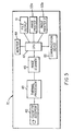
- FIG. 1 schematically illustrates a kiosk 7 for processing thermal film.
- Kiosk 7 includes a touch screen control 9 for consumer input.
- Touch screen control 9 eliminates the need for an additional keypad and promotes ease of operation.
- thermal film that provides satisfactory images can be utilized in the present invention.
- Typical films are full colored thermal films such as disclosed in U.S. Patent No. 5,698,365.
- a typical film provides light sensitive silver halides, compounds that form dyes, compounds that release dyes, couplers as dye donating compounds, reducing agents, and binders on supports.
- kiosk 7 is operationally associated with a network service provider 11 such as the internet via a modem 14.
- Network service provider 11 permits communication, connection and image and data transfer to remote locations. More specifically kiosk 7 can be connected to the internet via modem 14, cable line, wireless connection, or any other technology designed to allow two way communication.
- kiosk 7 can be adapted to receive a cassette including exposed film.
- the film is preferably located in a thrust cartridge.
- the thrust cartridge may be any cartridge that allows film to be withdrawn from the cartridge and rewound onto the cartridge multiple times while providing light- tight storage, particularly prior to exposure and development. Typical of such cartridges are those utilized in the advanced photo system (APS) for color negative film. These cartridges are disclosed in U.S. Patent No. 4,834,306 to Robertson et al. and U.S. Patent No. 4,832,275 to Robertson.
- U.S. Patent No. 6,048,110, and U.S. Patent No. 6,062,746 illustrate a further example of an apparatus for thermal development of thermal film using a thrust cartridge, with the apparatus including a magnetic reader and writer and a scanner.
- kiosk 7 can be adapted to receive a thrust cartridge in which a prepay identifier is placed on the film cassette.
- a preferred implementation of this system for a thermal film would be to allow the consumer to pay for processing at the time of film purchase. This would have the advantage of simplifying the design of kiosk 7 and its operating system by removing the need for a payment transaction. It would also provide enhanced and quicker operation for a consumer. With reference to Figs. 2A-2D, this system would involve marking a cassette 17 to indicate that the processing has been prepaid.
- This marking could take the form of (1) a printed element 19 on cassette 17 as shown in Fig 2A; (2) a feature in the design of the cassette, such as the cassette shape or color; (3) a mechanical component 21 of cassette 17 as shown in Fig. 2B; (4) an electronic component 23 on cassette 17 as shown in Fig 2C; or (5) a marking or recording 25 on film element 30 contained in cassette 17 as shown in Fig. 2D.
- Printed element 19 (Fig. 2A) on cassette 17 could be a bar code and id number or some other human readable or machine readable information source.
- Mechanical component 21 (Fig. 2B) could be a lever or other mechanical device indicating that the processing is prepaid.
- Electronic component 23 (Fig.
- FIG. 2C could take the form of an electrically readable device ranging from electrical contacts (similar to DX coding) to a more sophisticated electronic device using semiconductors and microprocessing, such as a smart chip.
- Marking or recording 25 (Fig 2D) on film element 30 could take the form of recorded information on film magnetics (when present), optical information recorded on the processed film, or notches or perforations 27 (Fig 2D) on film element 30 indicative of prepaid status.
- Cassette 17 may have several indicators of being prepaid, so that the state is human and machine readable. The use of redundant indicators, some of which are not human readable, would also serve to deter misuse of the system.
- the code, identifier or id can additionally be employed as described in EP Patent application Serial No. 00204163.0 to Szajewski et al., filed November 23, 2000.
- thermal film processing kiosk 7 can be enabled to receive single use cameras and process film therein.
- kiosk 7 would include an entry port 35 (Fig. 1) adapted to receive a single use camera having exposed thermal film.
- Kiosk 7 would include an apparatus designed to remove or extract the film from the cassette in a specially designed one time use camera, and process it in accordance with the consumer request as input to touchscreen 9.
- One time use cameras containing dry-process films are described by Kamata in Japanese Kokai 11/237,682.
- One time use cameras designed for easy mechanical removal of imagewise exposed film are described by Zander in U.S. Patent No. 5,799,220 and by Zander et al. in U.S. Patent No. 5,903,789.
- Well known apparatuses for automatically extracting exposed camera formatted films from cartridges or cassettes for chemical processing are described in cited U.S. Patent nos. 5,113,351 and 5,627,016.
- Kiosk 7 can be physically configured as a robust stand alone unit (such as required by a commercial arcade game or automatic teller machine) or as a tabletop interface (such as required for a library personal computer or Internet connection).
- the components most likely to be bundled within a single physical box are the film cartridge, handling mechanism or cassette acceptor, the film thermal processor, and the film scanner.
- the remaining components may optionally be contained within the same box or as separate, free standing units.
- the image viewing screen touch screen, video CRT, compact flat panel LCD
- the customer interaction device touch screen, keyboard, voice activated sensor
- the central computer processing unit personal computer, remote networked computer, Internet server
- the output printer ink jet, thermal dye transfer, photo processing digital minilab
- the payment transaction device credit/debit card reader, cash or token acceptance device
- a second scanning station film driven scanner, flatbed scanner
- storage medium floppy disk, compact disk writer, Internet image upload
- the central communication device modem, cable line, wireless connection.
- One advantage of employing a pre-paid cassette is that security and/or fraud associated with the kiosk could be minimized, allowing more user or vendor freedom.
- all of the non-film contacting components could optionally be used for other tasks by the user or proprietor, including Internet connection, personal computer software, business invoicing, video games, and the like.
- Figs. 3-5 illustrate examples of processing workflows in thermal film processing kiosk 7, in which kiosk 7 can employ multiple channels to improve throughput.
- kiosk 7A contains at least the following: a cassette acceptor 40 to accept a film cassette and extract film so that it can be manipulated; a thermal processor 43 to thermally process the film; an image scanner 45 to scan and digitize the images generated on the thermally processed films; a central processing unit (CPU) 47 to digitally process the scanned images so as to provide a suitable digital file; a monitor 49 on which to view the images and the progress/status of the film processing; a printer 53 to print the digital files thus rendering a hardcopy output; a file output or digital file writer 51 such as a compact disc writer or a floppy disc writer to deliver a digital file output; and an electronic communication device 55 so that kiosk 7A can communicate with other computers, for instance using the world wide web or Internet.
- a cassette acceptor 40 to accept a film cassette and extract film so that it can be manipulated
- a thermal processor 43 to thermally process the film
- an image scanner 45 to scan and digitize the images generated on the thermally processed films
- Thermal processor 43 can include a heater, which can be any suitable type of heater.
- the heater can be a resistive heater in the form of a plate or drum, a radiant heater, heated liquid, dielectric, microwave conduction and convection.
- the apparatus can thermally process supplied films by the application of heated gasses or heated air.
- a method and the associated apparatus are disclosed by: Siryj U.S. Patent No. 4,371,246; Goldberg et al., U.S. Patent No. 4,358,192; Siryj et al., U.S. Patent No. 4,293,212; Scott, U.S. Patent No. 4,198,145; Quantor, U.S. Patent No. 4,052,732; Siryj, U.S. Patent No. 4,148,575 and Limoges, Research Disclosure, 176,023 (1978).
- radiant energy as disclosed by Chin et al. U.S. Patent No. 5,587,767 can be employed.
- the heated gases can be loaded with particles to form a heated fluidized bed for thermally processing the photothermographic film.
- the particles in the fluidized bed can serve to both transfer heat energy to the film and can serve to abrade dirt from the film surface during processing.
- Figs 4 and 5 illustrate two embodiments which address the issue of potential rate limiting components in a thermal processing kiosk in accordance with the present invention.
- FIG. 4 illustrates a thermal processing kiosk 7B in which image scanning is a rate limiting process.
- the rate limiting process is addressed or eliminated by employing two scanners 45a and 45b in place of the single scanner 45 of Fig. 3.
- Kiosk 7B of Fig. 4 also includes a film direction hardware 60 which is adapted to direct processed film to one scanner (45a or 45b) or the other as needed.
- Fig. 5 illustrates a thermal processing kiosk 7C in which image printing is a rate limiting process.
- the rate limiting is addressed or eliminated by employing two printers 53a, 53b in place of the single printer 53 of Fig 3.
- selection of the printer (53a, 53b) can be handled simply by selection within CPU 47, with both printers 53a, 53b having access to a common CPU.
- This version can contain optional hardware to bring printed images to the same location, such as in the case where the printed images are loaded into an envelope prior to pickup by the consumer.
- the present invention is not limited to the configurations for addressing rate process limitations as shown in Figs. 4 and 5.
- the kiosk can include two scanners and two printers, three scanners and one printer or any combination of scanners and printers which are adequate to address the rate limiting process.
- thermal processing kiosk in accordance with the present invention, provision is made to employ a low resolution prescan for implementation of a process in which a consumer can preliminarily select a photo ( Photoselect mode).
- thermal kiosk 7 of the present invention provides for a photographic process in which preliminary processed images appear in a very short time frame on a soft display 75 (Fig. 1). This allows the consumer to select which images are ultimately printed as well as select crop, zoom, and other features by way of touch screen 9.
- the photoselect mode can be implemented in the thermal processing kiosk in two modes. In mode 1, two scanners 53a, 53b as illustrated in Fig. 4 would be used. One of the two scanners 53a, 53b would yield a lower quality scan immediately after processing at processor 43. Images obtained from this lower quality scan are previewed or displayed on soft display 75 for the consumer, while higher quality scans are performed in the other scanner 53a, 53b in anticipation of future consumer selections.
- the scanning could be based on resolution, i.e.
- mode 2 the same scanner (45 in Figs. 3 or 5) is used to perform both scans.
- the single scanner 45 would be adapted to operate in a low quality rapid mode for the preview or display, and in a higher quality slower mode for the ultimate images.
- This second mode would utilize appropriate hardware to pass and rewind film for the two separate scans at the single scanner.
- reference patches on the film Such reference patches and methods are described in more detail by Reem et al. 5,667,944, Wheeler et al U.S. Pat. No. 5,649,260, Koeng at al U.S. Pat. No. 5,563,717, by Cosgrove et al U.S. Pat. No. 5,644,647, and in combination with films intended for scanning by Sowinski et al U.S. Pat. No. 6,021,277.
- this electronic signal is further manipulated to form a useful electronic record of the image.
- the electrical signal can be passed through an analog-to-digital converter and sent to a digital computer together with location information required for pixel (point) location within the image.
- the number of pixels collected in this manner can be varied as dictated by the desired image quality.
- Very low resolution images can have pixel counts of 192 x128 pixels per film frame, low resolution 384x256 pixels per frame, medium resolution 768x512 pixels per frame, high resolution 1536x1024 pixels per frame and very high resolution 3072x2048 pixels per frame or even 6144x4096 pixels per frame or even more.
- pixel counts or higher resolution translates into higher quality images because it enables higher sharpness and the ability to distinguish finer details especially at higher magnifications at viewing.
- These pixel counts relate to image frames having an aspect ratio of 1.5 to 1.
- Other pixel counts and frame aspect ratios can be employed as known in the art.
- On digitization, these scans can have a bit depth of between 6 bits per color per pixel and 16 bits per color per pixel or even more. The bit depth can preferably be between 8 bits and 12 bits per color per pixel. Larger bit depth translates into higher quality images because it enables superior tone and color quality.
- the electronic signal can form an electronic record that is suitable to allow reconstruction of the image into viewable forms such as computer monitor displayed images, television images, optically, mechanically or digitally printed images and displays and so forth all as known in the art.
- the formed image can be stored or transmitted to enable further manipulation or viewing.
- An image scanner is used to scan an imagewise exposed and photographically processed color element.
- an array detector such as an array charge-coupled device (CCD), or line-by-line using a linear array detector, such as a linear array CCD
- a sequence of R, G, and B picture element signals are generated that can be correlated with spatial location information provided from the scanner.
- Signal intensity and location information is fed to Digital Image Processor and the information is transformed into an electronic form R', G', and B' embodying the customer look preference, which can be stored in any convenient storage device or otherwise delivered to the customer by any convenient method.
- the signals corresponding to the imperfection can be employed to provide a software correction so as to render the imperfections less noticeable or totally non-noticeable in soft or hard copy form.
- the hardware, software and technique for achieving this type of imperfection reduction is described by Edgar in U. S. Patent 5,266,805 and by Edgar et al. in WO 98/31142, WO 98/34397, WO 99/40729, WO 99/42954.
- the developed image can be scanned multiple times by a combination of transmission and reflection scans, optionally in the infrared and the resultant files combined to produce a single file representative of the initial image.
- a combination of transmission and reflection scans optionally in the infrared and the resultant files combined to produce a single file representative of the initial image.
Abstract
Description
- The present invention relates to a thermal processing system and method for processing thermally developable film which includes a kiosk.
- In the conventional practice of color photography, silver halide film is developed by a chemical technique requiring several steps consisting of latent image developing, bleaching, fixing and washing with the active reagents supplied in dilute solutions. While this technique has been perfected over many years and results in exceptional images, the technique requires the delivery and disposal of several chemicals and precise control of times and temperatures of development. Further, because of the mechanical constraints inherent in a wet solution process, the conventional silver halide chemical development technique is not particularly suitable for utilization with compact developing apparatuses. Nevertheless, attempts to provide convenient processing in customer oriented kiosks have been described by Sabbagh in EPO Published Application 0,234,833; by Bostic in U.S. Patent No. 5,113,351; by Manico in U.S. Patent No 5,627,016 and by Meyers in U.S. Patent No. 5,664,253. These approaches have not proven to be viable because of the problems mentioned above. Further, the chemical technique which is a wet processing technique is also not easily performed in the home or small office.
- Imaging systems that do not rely on conventional wet processing have received increased attention in recent years. Photothermographic imaging systems have been employed for producing silver images. Typically, these imaging systems have exhibited very low levels of radiation-sensitivity and have been utilized primarily where only low imaging speeds are required. A method and apparatus for developing a heat developing film is disclosed in U.S. Patent No. 5,587,767 to Islam et al. Summaries of photothermographic imaging systems are published Research Disclosure, Volume 170, June 1978, Item 17029, and Volume 299, March 1989, Item 29963. Other heat development color photographic materials have been disclosed, for example, in U.S. Patent No. 4,021,240 to Cerquone et al. and U.S. Patent No. 5,698,365 to Tuguchi et al.
- In a related area, commercial products such as Color Dry Silver supplied from Minnesota Mining and Manufacturing Company and Pictography™ and Pictrostat™ supplied by Fuji Film Co., Ltd. that allow for the convenient production of prints suitable for direct viewing without further magnification have been on the market. These products however do not provide for the convenient development processing of films formatted for use in hand-held cameras because such films require high magnification before they are suitable for viewing. The processes and products of these manufacturers are incompatible with that need. An apparatus for thermal development that enables the use of a thrust cartridge is disclosed by Szajewski at al in US patent number 6,048,110 and by Stoebe et al. in U.S. Patent No. 6,062,746.
- There remains a need for a user friendly arrangement for processing film that is convenient, rapid and gives the consumer multiple processing options.
- The present invention therefore provides for a thermal processing system and method which incorporates a multi-functional kiosk, is user friendly and facilitates image processing.
- The present invention relates to a thermal processing kiosk which comprises a user interface control for inputting information; an opening adapted to accept a film cassette containing exposed thermal film therein; a thermal processor for processing said exposed thermal film at least in accordance with the information to develop images on the film; and a scanner for scanning the images to create a digital image record file of the images.
- The present invention further relates to an image processing method which comprises the steps of: purchasing photographic film and paying for processing of the film prior to exposure of the purchased film; and associating an identifier with the photographic film indicating that processing for the film has been pre-paid.
- The present invention further relates to a photographic film cassette having unexposed film therein, wherein an identifier is associated with at least one of the cassette or the film to indicate that processing for the unexposed film in the cassette has been pre-paid.
- Fig. 1 is a schematic illustration of a thermal processing kiosk in accordance with the present invention;
- Figs. 2A-2D illustrate features of film cassettes and film in accordance with the present invention;
- Fig. 3 illustrates features of a thermal kiosk processor, and
- Figs. 4-5 illustrate further examples of thermal kiosk processors in accordance with additional features of the present invention.
-
- Referring now to the drawings, wherein like reference numerals represent identical or corresponding parts throughout the several views, Fig. 1 schematically illustrates a
kiosk 7 for processing thermal film. Kiosk 7 includes atouch screen control 9 for consumer input.Touch screen control 9 eliminates the need for an additional keypad and promotes ease of operation. - Any thermal film that provides satisfactory images can be utilized in the present invention. Typical films are full colored thermal films such as disclosed in U.S. Patent No. 5,698,365. A typical film provides light sensitive silver halides, compounds that form dyes, compounds that release dyes, couplers as dye donating compounds, reducing agents, and binders on supports.
- As also shown in Fig. 1,
kiosk 7 is operationally associated with a network service provider 11 such as the internet via amodem 14. Network service provider 11 permits communication, connection and image and data transfer to remote locations. More specifically kiosk 7 can be connected to the internet viamodem 14, cable line, wireless connection, or any other technology designed to allow two way communication. This can enable a variety of activities including transfer of generated images to a central storage site which can be accessed by a consumer or which has the purpose of generating hardcopy or digital file output that can be sent to a consumer; exchange of information related to purchasing of services, such as credit card numbers and authorizations; exchange of information on consumer habits; download of information to the kiosk for update of operating systems, advertising banners, modifications of behavior to compensate for recently released films; upload of information to a control center relating to equipment maintenance and malfunctions. - In a further feature of
kiosk 7 of the present invention,kiosk 7 can be adapted to receive a cassette including exposed film. The film is preferably located in a thrust cartridge. The thrust cartridge may be any cartridge that allows film to be withdrawn from the cartridge and rewound onto the cartridge multiple times while providing light- tight storage, particularly prior to exposure and development. Typical of such cartridges are those utilized in the advanced photo system (APS) for color negative film. These cartridges are disclosed in U.S. Patent No. 4,834,306 to Robertson et al. and U.S. Patent No. 4,832,275 to Robertson. - Already cited U.S. Patent No. 6,048,110, and U.S. Patent No. 6,062,746 illustrate a further example of an apparatus for thermal development of thermal film using a thrust cartridge, with the apparatus including a magnetic reader and writer and a scanner.
- In a further feature of the invention,
kiosk 7 can be adapted to receive a thrust cartridge in which a prepay identifier is placed on the film cassette. A preferred implementation of this system for a thermal film would be to allow the consumer to pay for processing at the time of film purchase. This would have the advantage of simplifying the design ofkiosk 7 and its operating system by removing the need for a payment transaction. It would also provide enhanced and quicker operation for a consumer. With reference to Figs. 2A-2D, this system would involve marking acassette 17 to indicate that the processing has been prepaid. This marking could take the form of (1) a printedelement 19 oncassette 17 as shown in Fig 2A; (2) a feature in the design of the cassette, such as the cassette shape or color; (3) amechanical component 21 ofcassette 17 as shown in Fig. 2B; (4) anelectronic component 23 oncassette 17 as shown in Fig 2C; or (5) a marking or recording 25 onfilm element 30 contained incassette 17 as shown in Fig. 2D. Printed element 19 (Fig. 2A) oncassette 17 could be a bar code and id number or some other human readable or machine readable information source. Mechanical component 21 (Fig. 2B) could be a lever or other mechanical device indicating that the processing is prepaid. Electronic component 23 (Fig. 2C) could take the form of an electrically readable device ranging from electrical contacts (similar to DX coding) to a more sophisticated electronic device using semiconductors and microprocessing, such as a smart chip. Marking or recording 25 (Fig 2D) onfilm element 30 could take the form of recorded information on film magnetics (when present), optical information recorded on the processed film, or notches or perforations 27 (Fig 2D) onfilm element 30 indicative of prepaid status.Cassette 17 may have several indicators of being prepaid, so that the state is human and machine readable. The use of redundant indicators, some of which are not human readable, would also serve to deter misuse of the system. The code, identifier or id can additionally be employed as described in EP Patent application Serial No. 00204163.0 to Szajewski et al., filed November 23, 2000. - In a further feature of the present invention, thermal
film processing kiosk 7 can be enabled to receive single use cameras and process film therein. In this implementation,kiosk 7 would include an entry port 35 (Fig. 1) adapted to receive a single use camera having exposed thermal film.Kiosk 7 would include an apparatus designed to remove or extract the film from the cassette in a specially designed one time use camera, and process it in accordance with the consumer request as input totouchscreen 9. One time use cameras containing dry-process films are described by Kamata in Japanese Kokai 11/237,682. One time use cameras designed for easy mechanical removal of imagewise exposed film are described by Zander in U.S. Patent No. 5,799,220 and by Zander et al. in U.S. Patent No. 5,903,789. Well known apparatuses for automatically extracting exposed camera formatted films from cartridges or cassettes for chemical processing are described in cited U.S. Patent nos. 5,113,351 and 5,627,016. -
Kiosk 7 can be physically configured as a robust stand alone unit (such as required by a commercial arcade game or automatic teller machine) or as a tabletop interface (such as required for a library personal computer or Internet connection). The components most likely to be bundled within a single physical box are the film cartridge, handling mechanism or cassette acceptor, the film thermal processor, and the film scanner. The remaining components may optionally be contained within the same box or as separate, free standing units. These remaining components, separate from those components that should specifically contact the film and/or cartridge, are the image viewing screen (touch screen, video CRT, compact flat panel LCD), the customer interaction device (touch screen, keyboard, voice activated sensor) the central computer processing unit (personal computer, remote networked computer, Internet server), the output printer (ink jet, thermal dye transfer, photo processing digital minilab), the payment transaction device (credit/debit card reader, cash or token acceptance device), a second scanning station (film driven scanner, flatbed scanner), storage medium (floppy disk, compact disk writer, Internet image upload), or the central communication device (modem, cable line, wireless connection). One advantage of employing a pre-paid cassette is that security and/or fraud associated with the kiosk could be minimized, allowing more user or vendor freedom. In the case of a tabletop interface, all of the non-film contacting components could optionally be used for other tasks by the user or proprietor, including Internet connection, personal computer software, business invoicing, video games, and the like. - Figs. 3-5 illustrate examples of processing workflows in thermal
film processing kiosk 7, in whichkiosk 7 can employ multiple channels to improve throughput. - In
thermal processing kiosks kiosk 7A contains at least the following: acassette acceptor 40 to accept a film cassette and extract film so that it can be manipulated; athermal processor 43 to thermally process the film; animage scanner 45 to scan and digitize the images generated on the thermally processed films; a central processing unit (CPU) 47 to digitally process the scanned images so as to provide a suitable digital file; amonitor 49 on which to view the images and the progress/status of the film processing; aprinter 53 to print the digital files thus rendering a hardcopy output; a file output ordigital file writer 51 such as a compact disc writer or a floppy disc writer to deliver a digital file output; and anelectronic communication device 55 so thatkiosk 7A can communicate with other computers, for instance using the world wide web or Internet. - The thermal process of thermally developable film in accordance with the present invention typically involves the application of heat to thermal film.
Thermal processor 43 can include a heater, which can be any suitable type of heater. For example, the heater can be a resistive heater in the form of a plate or drum, a radiant heater, heated liquid, dielectric, microwave conduction and convection. Reference is made to already cited U.S. Patent No. 6,048,110 and 6,062,746 (the contents of which are herein incorporated by reference) for a description of a thermal processing system and thermal film. - In another embodiment, the apparatus can thermally process supplied films by the application of heated gasses or heated air. Specific examples of such a method and the associated apparatus are disclosed by: Siryj U.S. Patent No. 4,371,246; Goldberg et al., U.S. Patent No. 4,358,192; Siryj et al., U.S. Patent No. 4,293,212; Scott, U.S. Patent No. 4,198,145; Quantor, U.S. Patent No. 4,052,732; Siryj, U.S. Patent No. 4,148,575 and Limoges, Research Disclosure, 176,023 (1978). Alternatively, radiant energy as disclosed by Chin et al. U.S. Patent No. 5,587,767 can be employed.
- In another embodiment, the heated gases can be loaded with particles to form a heated fluidized bed for thermally processing the photothermographic film. In this embodiment, the particles in the fluidized bed can serve to both transfer heat energy to the film and can serve to abrade dirt from the film surface during processing.
- As is the case with typical mechanical systems attempting to achieve a high processing speed, some or all of the components illustrated in Fig. 3 may be rate limiting in the processing and output of film images. In that case, it is desirable to have a dual or multiple channel of processing to improve the output of those elements that would be rate limiting. Figs 4 and 5 illustrate two embodiments which address the issue of potential rate limiting components in a thermal processing kiosk in accordance with the present invention.
- In the embodiments of Figs. 4 and 5, those elements which correspond to the elements in Fig. 3 have the same reference numerals. The embodiment of Fig 4 illustrates a
thermal processing kiosk 7B in which image scanning is a rate limiting process. The rate limiting process is addressed or eliminated by employing twoscanners single scanner 45 of Fig. 3.Kiosk 7B of Fig. 4 also includes afilm direction hardware 60 which is adapted to direct processed film to one scanner (45a or 45b) or the other as needed. - The embodiment of Fig. 5 illustrates a
thermal processing kiosk 7C in which image printing is a rate limiting process. The rate limiting is addressed or eliminated by employing twoprinters single printer 53 of Fig 3. In this case, selection of the printer (53a, 53b) can be handled simply by selection withinCPU 47, with bothprinters - In a further feature of the thermal processing kiosk in accordance with the present invention, provision is made to employ a low resolution prescan for implementation of a process in which a consumer can preliminarily select a photo ( Photoselect mode).
- More specifically,
thermal kiosk 7 of the present invention provides for a photographic process in which preliminary processed images appear in a very short time frame on a soft display 75 (Fig. 1). This allows the consumer to select which images are ultimately printed as well as select crop, zoom, and other features by way oftouch screen 9. The photoselect mode can be implemented in the thermal processing kiosk in two modes. In mode 1, twoscanners scanners processor 43. Images obtained from this lower quality scan are previewed or displayed onsoft display 75 for the consumer, while higher quality scans are performed in theother scanner mode 2, the same scanner (45 in Figs. 3 or 5) is used to perform both scans. Thesingle scanner 45 would be adapted to operate in a low quality rapid mode for the preview or display, and in a higher quality slower mode for the ultimate images. This second mode would utilize appropriate hardware to pass and rewind film for the two separate scans at the single scanner. - It is further contemplated to make use of reference patches on the film. Such reference patches and methods are described in more detail by Reem et al. 5,667,944, Wheeler et al U.S. Pat. No. 5,649,260, Koeng at al U.S. Pat. No. 5,563,717, by Cosgrove et al U.S. Pat. No. 5,644,647, and in combination with films intended for scanning by Sowinski et al U.S. Pat. No. 6,021,277.
- Once distinguishable color records have been formed in the processed photographic elements, conventional techniques can be employed for retrieving the image information for each color record and manipulating the record for subsequent creation of a color balanced viewable image. For example, it is possible to scan the photographic element successively within the blue, green, and red regions of the spectrum or to incorporate blue, green, and red light within a single scanning beam that is divided and passed through blue, green, and red filters to form separate scanning beams for each color record. If other colors are imagewise present in the element, then appropriately colored light beams are employed. A simple technique is to scan the photographic element point-by-point along a series of laterally offset parallel scan paths. A sensor that converts radiation received into an electrical signal notes the intensity of light passing through the element at a scanning point. Most generally this electronic signal is further manipulated to form a useful electronic record of the image. For example, the electrical signal can be passed through an analog-to-digital converter and sent to a digital computer together with location information required for pixel (point) location within the image. The number of pixels collected in this manner can be varied as dictated by the desired image quality. Very low resolution images can have pixel counts of 192 x128 pixels per film frame, low resolution 384x256 pixels per frame, medium resolution 768x512 pixels per frame, high resolution 1536x1024 pixels per frame and very high resolution 3072x2048 pixels per frame or even 6144x4096 pixels per frame or even more. Higher pixel counts or higher resolution translates into higher quality images because it enables higher sharpness and the ability to distinguish finer details especially at higher magnifications at viewing. These pixel counts relate to image frames having an aspect ratio of 1.5 to 1. Other pixel counts and frame aspect ratios can be employed as known in the art. On digitization, these scans can have a bit depth of between 6 bits per color per pixel and 16 bits per color per pixel or even more. The bit depth can preferably be between 8 bits and 12 bits per color per pixel. Larger bit depth translates into higher quality images because it enables superior tone and color quality.
- The electronic signal can form an electronic record that is suitable to allow reconstruction of the image into viewable forms such as computer monitor displayed images, television images, optically, mechanically or digitally printed images and displays and so forth all as known in the art. The formed image can be stored or transmitted to enable further manipulation or viewing.
- An image scanner is used to scan an imagewise exposed and photographically processed color element. As the element is scanned pixel-by-pixel using an array detector, such as an array charge-coupled device (CCD), or line-by-line using a linear array detector, such as a linear array CCD, a sequence of R, G, and B picture element signals are generated that can be correlated with spatial location information provided from the scanner. Signal intensity and location information is fed to Digital Image Processor and the information is transformed into an electronic form R', G', and B' embodying the customer look preference, which can be stored in any convenient storage device or otherwise delivered to the customer by any convenient method. In one embodiment, it is specifically contemplated to scan a developed image to red, green and blue light to retrieve imagewise recorded information and to scan the same image to infrared light for the purpose of recording the location of non-image imperfections. When such an imperfection or "noise" scan is employed, the signals corresponding to the imperfection can be employed to provide a software correction so as to render the imperfections less noticeable or totally non-noticeable in soft or hard copy form. The hardware, software and technique for achieving this type of imperfection reduction is described by Edgar in U. S. Patent 5,266,805 and by Edgar et al. in WO 98/31142, WO 98/34397, WO 99/40729, WO 99/42954. Further, the developed image can be scanned multiple times by a combination of transmission and reflection scans, optionally in the infrared and the resultant files combined to produce a single file representative of the initial image. Such a procedure is described by Edgar at US Patents 5,465,155, 5,519,510, 5,790,277, and 5,988,896, and by Edgar et al at EP-A-0 944,998, WO 99/43148, and WO 99/43149.
Claims (10)
- A thermal processing kiosk (7) comprising:a user interface control (9) for inputting information;an opening (40) adapted to accept a film cassette containing exposed thermal film therein;a thermal processor (43) for processing said exposed thermal film at least in accordance with said information to develop images on said film; anda scanner (45) for scanning said images to create a digital image record file of said images.
- A kiosk according to claim 1, further comprising:
a further opening adapted to accept a single use camera with exposed film therein for processing. - A kiosk according to claim 1, further comprising:a monitor (40) for viewing the images and monitoring a status of the processing at said thermal processor and said scanner,a printer (53) for printing a hard copy output of said images; andan electronic communication interface (55) for downloading the images onto a network service provider.
- A kiosk according to claim 1, comprising a further scanner (45a, 45b) and a film direction controller for directing the processed film to either said scanner or said further scanner based on a work flow in said scanner and said further scanner.
- A kiosk according to claim 1, wherein said kiosk has a photo select mode and comprises an image display to permit a preview of preliminary processed images, such that in said photo select mode the user can select which images are to be printed.
- An image processing method comprising the steps of:purchasing photographic film and paying for processing of the film prior to exposure of the purchased film; andassociating an identifier with the photographic film indicating that processing for the film has been pre-paid.
- A method according to claim 6, wherein after exposure of said film, the method comprises the further steps of:receiving said exposed film at a processing location;processing said exposed film to develop images on said film; andscanning said film to create a digital record file of images on said film.
- A method according to claim 7, wherein said processing location is a thermal processing kiosk and said film is thermal film.
- A photographic film cassette having unexposed film therein, wherein an identifier is associated with at least one of the cassette or the film to indicate that processing for the unexposed film in the cassette has been pre-paid.
- A thermal processing kiosk comprising:a user interface control (9) for inputting information;an opening (35) adapted to accept a single use camera with exposed thermal film therein;a thermal processor (43) for processing said exposed thermal film at least in accordance with said information to develop images on said film; anda scanner (45) for scanning said images to create a digital image record file of said images.
Applications Claiming Priority (2)
| Application Number | Priority Date | Filing Date | Title |
|---|---|---|---|
| US592836 | 2000-06-13 | ||
| US09/592,836 US6369873B1 (en) | 2000-06-13 | 2000-06-13 | Thermal processing system and method including a kiosk |
Publications (1)
| Publication Number | Publication Date |
|---|---|
| EP1164427A1 true EP1164427A1 (en) | 2001-12-19 |
Family
ID=24372263
Family Applications (1)
| Application Number | Title | Priority Date | Filing Date |
|---|---|---|---|
| EP01202080A Withdrawn EP1164427A1 (en) | 2000-06-13 | 2001-05-31 | A thermal processing system and method including a kiosk |
Country Status (9)
| Country | Link |
|---|---|
| US (1) | US6369873B1 (en) |
| EP (1) | EP1164427A1 (en) |
| JP (1) | JP2002062630A (en) |
| KR (1) | KR20010112621A (en) |
| CN (1) | CN1178104C (en) |
| BR (1) | BR0102369A (en) |
| CA (1) | CA2344603A1 (en) |
| HK (1) | HK1042953A1 (en) |
| TW (1) | TW497002B (en) |
Cited By (1)
| Publication number | Priority date | Publication date | Assignee | Title |
|---|---|---|---|---|
| EP1369827A2 (en) * | 2002-06-06 | 2003-12-10 | Eastman Kodak Company | System and method for providing a customized imaging product or service |
Families Citing this family (9)
| Publication number | Priority date | Publication date | Assignee | Title |
|---|---|---|---|---|
| US20030211188A1 (en) * | 2000-06-19 | 2003-11-13 | Kachnic Edward F. | Wireless image processing method and device therefor |
| CN1447742A (en) * | 2000-06-19 | 2003-10-08 | 爱德华·卡琴尼克 | Part forming machine integrated controller |
| JP2002109631A (en) * | 2000-10-02 | 2002-04-12 | Minolta Co Ltd | Storage medium for image data, digital camera and image processing device using the same |
| JP2002221769A (en) * | 2000-11-27 | 2002-08-09 | Fuji Photo Film Co Ltd | Heat developable photosensitive material and method of forming image using the same |
| US7167261B2 (en) * | 2001-12-28 | 2007-01-23 | Kabushiki Kaisha Toshiba | Image forming apparatus with predetermined copy quality set by user or operator |
| US7183024B2 (en) * | 2003-06-12 | 2007-02-27 | Eastman Kodak Company | High-speed positive-working photothermographic system |
| US7198889B2 (en) * | 2003-06-12 | 2007-04-03 | Eastman Kodak Company | High-speed positive-working photothermographic system comprising an accelerating agent |
| US7585449B2 (en) * | 2003-11-20 | 2009-09-08 | Nicol William A | Sensory system and method thereof |
| WO2009012148A1 (en) * | 2007-07-13 | 2009-01-22 | Kent Suzuki | Integrated interactive drawing and entertainment projector |
Citations (5)
| Publication number | Priority date | Publication date | Assignee | Title |
|---|---|---|---|---|
| EP0234833A2 (en) * | 1986-02-14 | 1987-09-02 | Samuel Sabbagh | A vending and dispensing system |
| US4903057A (en) * | 1988-01-29 | 1990-02-20 | Fuji Photo Film Co., Ltd. | Apparatus for producing photograph |
| US5113351A (en) * | 1989-03-29 | 1992-05-12 | Delphi Technology, Inc. | Automated, interactive vending system for products which must be processed |
| EP0741327A1 (en) * | 1995-05-04 | 1996-11-06 | Xerox Corporation | A film processor and method of developing film |
| US5664253A (en) * | 1995-09-12 | 1997-09-02 | Eastman Kodak Company | Stand alone photofinishing apparatus |
Family Cites Families (34)
| Publication number | Priority date | Publication date | Assignee | Title |
|---|---|---|---|---|
| US4052732A (en) | 1975-07-21 | 1977-10-04 | Quantor Corporation | Apparatus for developing and fixing heat sensitive film |
| US4021240A (en) | 1975-12-22 | 1977-05-03 | Eastman Kodak Company | Photothermographic and thermographic compositions and uses therefor containing sulfonamidophenol reducing agents and four equivalent color couplers |
| US4198145A (en) | 1977-04-25 | 1980-04-15 | Rca Corporation | Apparatus for developing photographic images on an emulsion coated film |
| US4293212A (en) | 1977-04-25 | 1981-10-06 | Rca Corporation | Thermal processor in an apparatus for developing photographic film |
| US4148575A (en) | 1977-07-22 | 1979-04-10 | Rca Corporation | Thermal processor |
| US4358192A (en) | 1980-08-14 | 1982-11-09 | Wavetek Indiana, Inc. | Apparatus and method for processing heat developed photosensitive recording material |
| US4371246A (en) | 1981-02-13 | 1983-02-01 | Rca Corporation | Thermal processor |
| US4834306A (en) | 1988-03-25 | 1989-05-30 | Eastman Kodak Company | Film cassette |
| US4832275A (en) | 1988-05-19 | 1989-05-23 | Eastman Kodak Company | Film cassette |
| US5644647A (en) | 1990-09-17 | 1997-07-01 | Eastman Kodak Company | User-interactive reduction of scene balance failures |
| US5266805A (en) | 1992-05-05 | 1993-11-30 | International Business Machines Corporation | System and method for image recovery |
| CA2093449C (en) | 1992-07-17 | 1997-06-17 | Albert D. Edgar | Electronic film development |
| CA2093840C (en) | 1992-07-17 | 1999-08-10 | Albert D. Edgar | Duplex film scanning |
| US5790277A (en) | 1994-06-08 | 1998-08-04 | International Business Machines Corporation | Duplex film scanning |
| JP3349608B2 (en) | 1994-11-17 | 2002-11-25 | 富士写真フイルム株式会社 | Thermal development color photosensitive material |
| US5563717A (en) | 1995-02-03 | 1996-10-08 | Eastman Kodak Company | Method and means for calibration of photographic media using pre-exposed miniature images |
| US5649260A (en) | 1995-06-26 | 1997-07-15 | Eastman Kodak Company | Automated photofinishing apparatus |
| US5667944A (en) | 1995-10-25 | 1997-09-16 | Eastman Kodak Company | Digital process sensitivity correction |
| US5627016A (en) | 1996-02-29 | 1997-05-06 | Eastman Kodak Company | Method and apparatus for photofinishing photosensitive film |
| US5988896A (en) | 1996-10-26 | 1999-11-23 | Applied Science Fiction, Inc. | Method and apparatus for electronic film development |
| US6069714A (en) | 1996-12-05 | 2000-05-30 | Applied Science Fiction, Inc. | Method and apparatus for reducing noise in electronic film development |
| US6442301B1 (en) | 1997-01-06 | 2002-08-27 | Applied Science Fiction, Inc. | Apparatus and method for defect channel nulling |
| US6380539B1 (en) | 1997-01-30 | 2002-04-30 | Applied Science Fiction, Inc. | Four color trilinear CCD scanning |
| US5799220A (en) | 1997-07-22 | 1998-08-25 | Eastman Kodak Company | Camera with actuator for moving sprocket wheel to film engaging position when door closed |
| US5903789A (en) | 1997-07-22 | 1999-05-11 | Eastman Kodak Company | Camera with actuator for opening closed door and retracting sprocket wheel from film engageable position |
| JPH11237682A (en) | 1997-12-17 | 1999-08-31 | Fuji Photo Film Co Ltd | Film unit with lens |
| US6590679B1 (en) | 1998-02-04 | 2003-07-08 | Applied Science Fiction, Inc. | Multilinear array sensor with an infrared line |
| EP1078505A1 (en) | 1998-02-23 | 2001-02-28 | Applied Science Fiction, Inc. | Parametric image stitching |
| WO1999043149A1 (en) | 1998-02-23 | 1999-08-26 | Applied Science Fiction, Inc. | Progressive area scan in electronic film development |
| EP1057142A1 (en) | 1998-02-23 | 2000-12-06 | Applied Science Fiction, Inc. | Image processing method using a block overlap transformation procedure |
| US6021277A (en) | 1998-06-25 | 2000-02-01 | Eastman Kodak Company | One-time-use camera preloaded with color negative film element |
| US6062746A (en) | 1998-12-07 | 2000-05-16 | Eastman Kodak Company | Compact apparatus for thermal film development and scanning |
| US6048110A (en) | 1998-12-07 | 2000-04-11 | Eastman Kodak Company | Compact thermal film apparatus with magnetic sensing device |
| US6242166B1 (en) * | 1999-12-30 | 2001-06-05 | Eastman Kodak Company | Packaged color photographic film comprising a blocked phenyldiamine chromogenic developer |
-
2000
- 2000-06-13 US US09/592,836 patent/US6369873B1/en not_active Expired - Fee Related
-
2001
- 2001-04-13 TW TW090108914A patent/TW497002B/en not_active IP Right Cessation
- 2001-04-19 CA CA002344603A patent/CA2344603A1/en not_active Abandoned
- 2001-05-31 EP EP01202080A patent/EP1164427A1/en not_active Withdrawn
- 2001-06-12 KR KR1020010032725A patent/KR20010112621A/en not_active Application Discontinuation
- 2001-06-12 BR BR0102369-1A patent/BR0102369A/en not_active IP Right Cessation
- 2001-06-13 JP JP2001178529A patent/JP2002062630A/en active Pending
- 2001-06-13 CN CNB011212942A patent/CN1178104C/en not_active Expired - Fee Related
-
2002
- 2002-06-24 HK HK02104679.8A patent/HK1042953A1/en unknown
Patent Citations (5)
| Publication number | Priority date | Publication date | Assignee | Title |
|---|---|---|---|---|
| EP0234833A2 (en) * | 1986-02-14 | 1987-09-02 | Samuel Sabbagh | A vending and dispensing system |
| US4903057A (en) * | 1988-01-29 | 1990-02-20 | Fuji Photo Film Co., Ltd. | Apparatus for producing photograph |
| US5113351A (en) * | 1989-03-29 | 1992-05-12 | Delphi Technology, Inc. | Automated, interactive vending system for products which must be processed |
| EP0741327A1 (en) * | 1995-05-04 | 1996-11-06 | Xerox Corporation | A film processor and method of developing film |
| US5664253A (en) * | 1995-09-12 | 1997-09-02 | Eastman Kodak Company | Stand alone photofinishing apparatus |
Cited By (2)
| Publication number | Priority date | Publication date | Assignee | Title |
|---|---|---|---|---|
| EP1369827A2 (en) * | 2002-06-06 | 2003-12-10 | Eastman Kodak Company | System and method for providing a customized imaging product or service |
| EP1369827A3 (en) * | 2002-06-06 | 2004-03-31 | Eastman Kodak Company | System and method for providing a customized imaging product or service |
Also Published As
| Publication number | Publication date |
|---|---|
| CN1178104C (en) | 2004-12-01 |
| JP2002062630A (en) | 2002-02-28 |
| TW497002B (en) | 2002-08-01 |
| BR0102369A (en) | 2002-02-19 |
| CA2344603A1 (en) | 2001-12-13 |
| KR20010112621A (en) | 2001-12-20 |
| US6369873B1 (en) | 2002-04-09 |
| CN1329272A (en) | 2002-01-02 |
| HK1042953A1 (en) | 2002-08-30 |
Similar Documents
| Publication | Publication Date | Title |
|---|---|---|
| US5799219A (en) | System and method for remote image communication and processing using data recorded on photographic film | |
| US6373551B2 (en) | System and method for communication of digital images generated from photographic film | |
| TW505821B (en) | Imaging processing method, imaging system, and method of providing image processing services by a photofinisher to a customer | |
| US6786655B2 (en) | Method and system for self-service film processing | |
| US6967737B2 (en) | Print ordering method, printing system and film scanner | |
| US6707531B2 (en) | Automatic self-service installation for printing photographs stored in digital form | |
| JP3653334B2 (en) | Image printing apparatus and system, and image file apparatus and system | |
| US6554504B2 (en) | Distributed digital film processing system and method | |
| US6369873B1 (en) | Thermal processing system and method including a kiosk | |
| US6215559B1 (en) | Image queing in photofinishing | |
| JP2001320654A (en) | Photo service system and image input device | |
| US6714736B2 (en) | System and method for communication of digital images generated from photographic film | |
| US7130067B1 (en) | Image data management system for image processing | |
| EP1298487A1 (en) | Image data storing service system | |
| JP2002073794A (en) | System for providing image data management service | |
| JP2006323452A (en) | Print order receiving machine | |
| JPH10171027A (en) | Method and system for printing picture | |
| JP3632833B2 (en) | Photo printing device | |
| JP2004252448A (en) | System and method for automatic image processing | |
| JPH11234476A (en) | Photographic material processing unit | |
| JPH11282089A (en) | Printer, and recording medium having image information recorded | |
| JP3538795B2 (en) | Exposure equipment and development processing equipment | |
| JPH10269286A (en) | Print ordering method, its system, and film scanner | |
| JPH10271251A (en) | Film scanner and digital print system | |
| JPH1013589A (en) | Photograph print system |
Legal Events
| Date | Code | Title | Description |
|---|---|---|---|
| PUAI | Public reference made under article 153(3) epc to a published international application that has entered the european phase |
Free format text: ORIGINAL CODE: 0009012 |
|
| AK | Designated contracting states |
Kind code of ref document: A1 Designated state(s): AT BE CH CY DE DK ES FI FR GB GR IE IT LI LU MC NL PT SE TR |
|
| AX | Request for extension of the european patent |
Free format text: AL;LT;LV;MK;RO;SI |
|
| 17P | Request for examination filed |
Effective date: 20020531 |
|
| AKX | Designation fees paid |
Free format text: AT BE CH CY DE DK ES FI FR GB GR IE IT LI LU MC NL PT SE TR |
|
| 17Q | First examination report despatched |
Effective date: 20040401 |
|
| STAA | Information on the status of an ep patent application or granted ep patent |
Free format text: STATUS: THE APPLICATION IS DEEMED TO BE WITHDRAWN |
|
| 18D | Application deemed to be withdrawn |
Effective date: 20061201 |