EP1165906B1 - Panel and fastening system for panels - Google Patents
Panel and fastening system for panels Download PDFInfo
- Publication number
- EP1165906B1 EP1165906B1 EP99957872A EP99957872A EP1165906B1 EP 1165906 B1 EP1165906 B1 EP 1165906B1 EP 99957872 A EP99957872 A EP 99957872A EP 99957872 A EP99957872 A EP 99957872A EP 1165906 B1 EP1165906 B1 EP 1165906B1
- Authority
- EP
- European Patent Office
- Prior art keywords
- panel
- panels
- fastening system
- projection
- hook
- Prior art date
- Legal status (The legal status is an assumption and is not a legal conclusion. Google has not performed a legal analysis and makes no representation as to the accuracy of the status listed.)
- Expired - Lifetime
Links
- 238000005304 joining Methods 0.000 claims description 20
- 239000000463 material Substances 0.000 claims description 20
- 230000000295 complement effect Effects 0.000 claims description 18
- 239000011324 bead Substances 0.000 claims description 13
- 239000000945 filler Substances 0.000 claims description 11
- 238000010276 construction Methods 0.000 claims description 8
- 239000000758 substrate Substances 0.000 claims description 3
- 239000011093 chipboard Substances 0.000 claims description 2
- 208000029154 Narrow face Diseases 0.000 claims 22
- 239000000853 adhesive Substances 0.000 claims 1
- 230000001070 adhesive effect Effects 0.000 claims 1
- 238000009408 flooring Methods 0.000 claims 1
- 230000005489 elastic deformation Effects 0.000 description 15
- 238000009434 installation Methods 0.000 description 15
- 230000001788 irregular Effects 0.000 description 10
- 239000003292 glue Substances 0.000 description 8
- 238000004519 manufacturing process Methods 0.000 description 6
- 238000000034 method Methods 0.000 description 6
- 230000008569 process Effects 0.000 description 6
- 230000008901 benefit Effects 0.000 description 5
- 239000011094 fiberboard Substances 0.000 description 4
- 238000005452 bending Methods 0.000 description 3
- 238000005520 cutting process Methods 0.000 description 3
- 230000006872 improvement Effects 0.000 description 3
- 238000004026 adhesive bonding Methods 0.000 description 2
- 230000008859 change Effects 0.000 description 2
- 230000007423 decrease Effects 0.000 description 2
- 238000003801 milling Methods 0.000 description 2
- 206010023230 Joint stiffness Diseases 0.000 description 1
- 238000005299 abrasion Methods 0.000 description 1
- 238000010521 absorption reaction Methods 0.000 description 1
- 230000015572 biosynthetic process Effects 0.000 description 1
- 239000000969 carrier Substances 0.000 description 1
- 239000012876 carrier material Substances 0.000 description 1
- 239000011248 coating agent Substances 0.000 description 1
- 238000000576 coating method Methods 0.000 description 1
- 230000002349 favourable effect Effects 0.000 description 1
- 210000003746 feather Anatomy 0.000 description 1
- 238000007667 floating Methods 0.000 description 1
- 239000011888 foil Substances 0.000 description 1
- 230000003993 interaction Effects 0.000 description 1
- 230000009916 joint effect Effects 0.000 description 1
- 238000003754 machining Methods 0.000 description 1
- 230000035515 penetration Effects 0.000 description 1
- 238000009418 renovation Methods 0.000 description 1
- 230000002441 reversible effect Effects 0.000 description 1
- 238000004904 shortening Methods 0.000 description 1
- 239000007787 solid Substances 0.000 description 1
- 230000008961 swelling Effects 0.000 description 1
- 239000002699 waste material Substances 0.000 description 1
Images

Classifications
-
- E—FIXED CONSTRUCTIONS
- E04—BUILDING
- E04F—FINISHING WORK ON BUILDINGS, e.g. STAIRS, FLOORS
- E04F15/00—Flooring
- E04F15/02—Flooring or floor layers composed of a number of similar elements
-
- B—PERFORMING OPERATIONS; TRANSPORTING
- B27—WORKING OR PRESERVING WOOD OR SIMILAR MATERIAL; NAILING OR STAPLING MACHINES IN GENERAL
- B27F—DOVETAILED WORK; TENONS; SLOTTING MACHINES FOR WOOD OR SIMILAR MATERIAL; NAILING OR STAPLING MACHINES
- B27F1/00—Dovetailed work; Tenons; Making tongues or grooves; Groove- and- tongue jointed work; Finger- joints
- B27F1/02—Making tongues or grooves, of indefinite length
- B27F1/04—Making tongues or grooves, of indefinite length along only one edge of a board
-
- E—FIXED CONSTRUCTIONS
- E04—BUILDING
- E04F—FINISHING WORK ON BUILDINGS, e.g. STAIRS, FLOORS
- E04F15/00—Flooring
- E04F15/02—Flooring or floor layers composed of a number of similar elements
- E04F15/04—Flooring or floor layers composed of a number of similar elements only of wood or with a top layer of wood, e.g. with wooden or metal connecting members
-
- E—FIXED CONSTRUCTIONS
- E04—BUILDING
- E04F—FINISHING WORK ON BUILDINGS, e.g. STAIRS, FLOORS
- E04F2201/00—Joining sheets or plates or panels
- E04F2201/01—Joining sheets, plates or panels with edges in abutting relationship
- E04F2201/0107—Joining sheets, plates or panels with edges in abutting relationship by moving the sheets, plates or panels substantially in their own plane, perpendicular to the abutting edges
- E04F2201/0115—Joining sheets, plates or panels with edges in abutting relationship by moving the sheets, plates or panels substantially in their own plane, perpendicular to the abutting edges with snap action of the edge connectors
-
- E—FIXED CONSTRUCTIONS
- E04—BUILDING
- E04F—FINISHING WORK ON BUILDINGS, e.g. STAIRS, FLOORS
- E04F2201/00—Joining sheets or plates or panels
- E04F2201/01—Joining sheets, plates or panels with edges in abutting relationship
- E04F2201/0138—Joining sheets, plates or panels with edges in abutting relationship by moving the sheets, plates or panels perpendicular to the main plane
- E04F2201/0146—Joining sheets, plates or panels with edges in abutting relationship by moving the sheets, plates or panels perpendicular to the main plane with snap action of the edge connectors
-
- E—FIXED CONSTRUCTIONS
- E04—BUILDING
- E04F—FINISHING WORK ON BUILDINGS, e.g. STAIRS, FLOORS
- E04F2201/00—Joining sheets or plates or panels
- E04F2201/01—Joining sheets, plates or panels with edges in abutting relationship
- E04F2201/0153—Joining sheets, plates or panels with edges in abutting relationship by rotating the sheets, plates or panels around an axis which is parallel to the abutting edges, possibly combined with a sliding movement
-
- E—FIXED CONSTRUCTIONS
- E04—BUILDING
- E04F—FINISHING WORK ON BUILDINGS, e.g. STAIRS, FLOORS
- E04F2201/00—Joining sheets or plates or panels
- E04F2201/02—Non-undercut connections, e.g. tongue and groove connections
- E04F2201/023—Non-undercut connections, e.g. tongue and groove connections with a continuous tongue or groove
-
- E—FIXED CONSTRUCTIONS
- E04—BUILDING
- E04F—FINISHING WORK ON BUILDINGS, e.g. STAIRS, FLOORS
- E04F2201/00—Joining sheets or plates or panels
- E04F2201/02—Non-undercut connections, e.g. tongue and groove connections
- E04F2201/025—Non-undercut connections, e.g. tongue and groove connections with tongue and grooves alternating transversally in the direction of the thickness of the panel, e.g. multiple tongue and grooves oriented parallel to each other
-
- E—FIXED CONSTRUCTIONS
- E04—BUILDING
- E04F—FINISHING WORK ON BUILDINGS, e.g. STAIRS, FLOORS
- E04F2201/00—Joining sheets or plates or panels
- E04F2201/07—Joining sheets or plates or panels with connections using a special adhesive material
-
- Y—GENERAL TAGGING OF NEW TECHNOLOGICAL DEVELOPMENTS; GENERAL TAGGING OF CROSS-SECTIONAL TECHNOLOGIES SPANNING OVER SEVERAL SECTIONS OF THE IPC; TECHNICAL SUBJECTS COVERED BY FORMER USPC CROSS-REFERENCE ART COLLECTIONS [XRACs] AND DIGESTS
- Y10—TECHNICAL SUBJECTS COVERED BY FORMER USPC
- Y10T—TECHNICAL SUBJECTS COVERED BY FORMER US CLASSIFICATION
- Y10T403/00—Joints and connections
- Y10T403/65—Scarf
- Y10T403/655—Mirror images
Definitions
- the invention relates to a panel and a fastening system for panels with arranged on the narrow sides of the panels Retaining profiles, especially for floor panels on a Are to be laid underground, the holding profile of a long Narrow side and the holding profile of the opposite Narrow side as well as the holding profiles of the other two short ones Narrow sides of a panel fit together so that on the free narrow sides of a laid panel further panels are attachable, at least the holding profiles of the long Narrow sides of the panels as mutually associated positive locking profiles trained and the panels by a rotating joining movement are attachable to each other that the positive profile one of the long narrow sides of a panel has a recess and the opposite narrow side of this panel has a matching projection that the underground facing wall of the recess inside a cross section has a concave curvature and that the associated Positive locking profile on the opposite narrow side of the panel has a protrusion which is on its surface facing bottom a cross section with a convex Has curvature, and that the convex curvature of the
- Fastening systems of the type mentioned keep panels ready installed condition by a positive connection. Especially when laid floating on a surface Floor panels prevent a positive connection between the panels the creation of joints, for example through thermal expansion or shortening when the temperature drops can arise.
- the known fastening system is disadvantageously suitable only for particularly flat surfaces.
- irregular, rough and corrugated surfaces nestle a panel floor with the known fastening system only very poorly the shape of the irregular surface.
- a panel that is laid by the neighboring ones Panels with some air over a corrugated surface is pressed on the ground when loaded, so bend attached floor panels.
- This Deflection stresses the connection points in particular with the interlocking interlocking profiles.
- the interconnected panels are facing down or buckled up and from the normal installation level pushed out. Because of the high rigidity of the connection high stress occurs in the weak cross sections of the Form-fitting profiles, which damage very quickly become. The damage progresses quickly to a head start or a recess wall breaks.
- the invention is therefore based on the object, the known Fixing system so that the rigidity of the Connection of two interlocking positive locking profiles to the The connections are adapted to the stress when laying to endure the panels on an irregular surface to have.
- the object is achieved in that the positive-locking profiles the long narrow sides of two panels in the laid Condition of two panels form a joint, that the top of the projection facing away from the ground of a panel has an oblique material removal that extends to the free end of the projection that the Thickness of the projection due to the removal of material to the free End is increasingly reduced, and that through the removal of material a freedom of movement for the joint is created.
- the new construction allows articulated movement of two interconnected panels.
- two interconnected panels at the junction be buckled at the top.
- a joint movement takes place.
- a floor laid with the proposed fastening system thus shows an irregular rough or wavy Elasticity adjusted to the substrate.
- the fastening system is therefore particularly suitable for renovation panels irregular floors in old buildings. Of course it is also for laying panels on one soft liner is more suitable than the known fastening system.
- the construction is based on the principle of "adapted deformability" Bill. This principle is based on the knowledge that very stiff and therefore supposedly stable connection points cause high notch stresses and therefore easily fail. To avoid this, components should be designed so that they are compliant to the purpose or "adapted deformability" and in this way Notch stresses can be reduced.
- the positive locking profiles are designed so that a load on the top of the floor panels in the installed Condition of the top wall of the recess of a first Panels in the projection of the second panel and from the projection of the second panel in the underside wall of the first Panels is transferred.
- the walls of the recess of the first When installed, panels have contact with the top and Bottom of the protrusion of the second panel.
- the recess has only a short area on the free end of the top wall of the recess contact with the Protrusion of the second panel. In this way, the Construction with little elastic deformation of the walls the recess a joint movement between the panel with the Recess and the panel with the tab. In this way the rigidity of the connection is best adapted to one irregular pad, which inevitably leads to a kinking movement between panels fastened together.
- panels are the fastening system according to the invention better for a multiple Laying are suitable as panels with the known fastening system, because the panels with the fastening system according to the invention even after long use on an irregular No pre-damage to the interlocking profiles exhibit.
- the form-fitting profiles are dimensionally stable and durable. They can be used much longer and during their life cycle be relocated more often.
- the convex curvature of the projection and the concave curvature of the cutout essentially a segment of a circle, where in the installed state the center of the circle Circular sections on the top of the tab or below the top of the projection is arranged. In the latter In this case, the center of the circle lies within the cross section of the Projection.
- the point is the convex one Bulge at the bottom of the protrusion, which is misplaced Most protruding towards the surface, arranged so that it is approximately below the top edge of the panel. This results in a ratio to the total thickness of the panel relatively strong cross section for the lead.
- the concave curvature offers the recess a sufficiently large undercut for the convex Curvature of the projection, so that this through in the installation level acting tensile forces can hardly be moved apart.
- the joint properties of two interconnected panels can be further improved if the wall of the recess of a panel facing the substrate has an inclined material removal on its inside, which extends to the free end of the wall and the wall thickness of this wall is increasingly thinner towards the free end.
- the removal of material when two panels are installed creates freedom of movement for the joint.
- the proportion of elastic deformation of the walls of the recess is further reduced during the deflection of the installed panels.
- the recess of a panel for connection to the projection of a further panel can be widened by a resilient deformation of its lower wall and that the resilient deformation of the lower wall which occurs during the joining is withdrawn again in the fully connected state of two panels.
- the form-fitting profiles are thus only elastically deformed for the joining process and during a joint movement and, if they are not loaded, are not subject to any elastic tension.
- the holding profiles are simply the short narrow side a panel with conventional approximately rectangular groove and Feather cross sections provided. These are very simple and inexpensive producible and can be added after joining the through the long narrow sides of a panel Bring each other sideways. Also can be the long narrow sides of the panels along their entire length in push in parallel direction.
- the form-fitting profiles are preferably in one piece on the narrow sides molded on the panels.
- the panels can be very easy and with little waste.
- the form-fitting profiles according to the invention are particularly suitable, if the panels are essentially made of MDF (medium Density Fiberboard), HDF (High Density Fiberboard) or one Chipboard material exist. These materials are simple to process and receive, for example by cutting Machining, adequate surface quality. Moreover these materials have a high dimensional stability of the milled Profiles on.
- MDF Medium Density Fiberboard
- HDF High Density Fiberboard
- the Panels with the freedom of movement for the common joints are provided with a soft elastic hardening filler.
- This filler preferably closes all joints and in particular the top joint so that no moisture and no dirt can enter.
- An alternative design of the fastening system provides that a short narrow side of a panel is a first hook element and the opposite short narrow side of the panel a second complementary to the first hook element Has hook element and that the hook elements with holding surfaces are provided, through which the panels are assembled are held against each other so that the short narrow sides a gap-free abutting surface the panels result.
- the form-fitting profiles must first be used the long narrow sides of the panels. For this, a panel is placed at an angle and with the projection a long narrow side in the recess of the long Narrow side of a laid panel inserted. This forms the common joint. Then the panel in the held at an inclined position and so far in its longitudinal direction moved until it was against the short narrow side of an adjacent one Panel bumps. In this position they overlap Hook elements on the short narrow sides of the adjacent panels. If now the inclined panel by means of the joint is folded down, the overlapping hook elements join each other. There is an undertaking that the Panels locked against pulling apart in their longitudinal direction. Due to the hook elements there is a degree of undercut achievable, at about a third of the total panel thickness lies. The way of locking the short narrow sides the panels are reminiscent of those that reach behind one another Roof tiles.
- the first hook element is simply one of the short narrow side protruding approximately vertically and on the Panel top arranged web formed, being on the free End of the bridge pointing towards the underside of the panel Hook projection is arranged and the second hook element one protruding from the opposite short narrow side and web arranged on the underside of the panel formed, one at the free end of this web to the top of the panel pointing hook projection is arranged.
- the top of the panel goes from the area with the thickness of the complete panel with a thickness gradation across in Web.
- the web has a thickness of about a third corresponds to the panel thickness.
- the bottom of the panel Opposite the top hook element the underside web goes from the area of the complete Thickness of the panel with a gradation across in the web, which is also about a third of the thickness of the panel.
- the webs and the hook projections are therefore relatively solid educated. Therefore, there is an improvement in strength and durability for the fastening system according to the invention.
- the hook projection of the underside is advantageously located Bridge in the assembled state of a panel on the top Web of a second panel. Also, between that Hook projection of the top web of the second panel and Air is provided on the underside web of the first panel.
- a further development of the fastening system provides that the holding surfaces of the hook projections engage behind in such a way that they can only be hooked into one another by elastic deformation are. In this way, the Hook elements, for example due to an uneven surface can be moved apart when loaded. With a load of a panel, the connected panel is loaded with the Panel moved in the same direction. The joint stay together.
- the holding surfaces are simply the hook projections slanted and the hook projections of their free ends towards the webs. Furthermore, the Holding surfaces of complementary hook jumps at least in some areas to each other. This is a simple one Design of the hook projections provided with an undercut, because as an undercut an easy to manufacture flat holding surface is provided.
- a screed At the bottom of the panels, for example, on a base a screed, can be placed in the area of An air gap between the panels can be tolerated.
- An alternative embodiment with hook elements on the short narrow sides of the panel is constructed so that at least one of the end faces of one of the hook elements of the panels has a projecting locking element at its free end, that in an undercut recess of the other hook element of the panel.
- This construction has proven to be turned out to be particularly easy to handle because the holding profiles with light pressure and with elastic deformation snap together.
- the holding elements good wear resistance on what a multiple laying favored. The wear resistance is good because different locking functions of different holding element areas are exercised and the stress on the holding element so distributed occurs.
- the panels for example through the locking element and the recess perpendicular to Laying level locked. The panels are locked against Pull apart in the longitudinal direction, however, by the holding surfaces of the hook projections accomplished.
- the protruding locking element is simply the first Panels formed as a bead that extends over the entire length the narrow side extends and the undercut recess of the second panel is formed as an elongated throat, which takes up the bead in the assembled state. For joining must bulge and throat under an elastic deformation of the Hook elements can be inserted into one another.
- This embodiment of the fastening system is then suitable if no gluing is done, especially good for one Multiple laying.
- the glued installation is considered the most expedient type of installation. This is because the durability of the panels is significantly improved becomes.
- the gluing of the holding profiles causes a Virtually penetration of dirt and moisture into the joints is prevented.
- the moisture absorption and swelling of the This minimizes panels in the joining area of the holding profiles.
- the panels are preferably made of a coated carrier material formed and the holding profiles in one piece on the narrow sides molded on the panels. It has been shown that the Strength of modern carriers, such as medium density Fiberboard (MDF) or high-density fiberboard (HDF), which are provided with an abrasion-resistant wear layer, are particularly interested in the use of the proposed fastening system suitable. Even after repeated laying, they are Holding profiles so well in shape that a secure connection is also possible on uneven surfaces.
- MDF medium density Fiberboard
- HDF high-density fiberboard
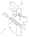
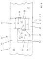
- the fastening system 1 is based on the example elongated rectangular panels 2 and 3 explained by which is shown in Fig. 1 a section.
- the fastening system 1 has arranged on the narrow sides of the panels Retaining profiles that act as complementary positive locking profiles 4 and 5 are formed.
- the opposite form-fitting profiles of a panel are each complementary. In this way, any panel that has already been installed can be installed 2 another panel 3 can be attached.
- the positive locking profiles 4 and 5 are based on the prior art of the German utility model G 79 28 703 U1. In particular on the form-fitting profiles of the embodiment that in Figures 14, 15 and 16 and in the associated description G 79 28 703 U1 is disclosed.
- the form-fitting profiles according to the invention are developed in such a way that they have an articulated and resilient connection of Enable panels.
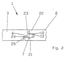
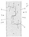
- One of the positive locking profiles 4 of the present invention is provided with a projection 6 protruding from the narrow side.
- the bottom of the projection 6, which is in the installed state facing the document points for the purpose of articulated Connection a cross section with a convex curvature 7.
- the convex curvature 7 is in the complementary form-fitting profile 5 pivoted.
- the convex curvature 7 is circular.
- the part 8 of the arranged below the projection 6 Narrow side of the panel 3, which is in the laid state of the underlay faces from the free end of the projection 6 further back than that arranged above the projection 6 Part 9 of the narrow side.
- the part 9 of the narrow side arranged above the projection 6 occurs at the top of the panel 3 from the narrow side protrudes and forms a joint joint surface 9a. Between this Joint joint surface 9a and the projection 6 of the panel 3 is the Part 9 of the narrow side reset. This ensures that part 9 of the narrow side is always a closed top Groove with the complementary narrow side of another panel 2 forms.
- the top of the projection 6 has a short straight section 11 on, also parallel to the ground in the installed state U is arranged. From this short section 11 to Free end, the top of the projection 6 has a inclined material removal 12, which extends to the free end of the projection 6 extends.
- the form-fitting profile complementary to the form-fitting profile 4 discussed 5 of a narrow side has a recess 20.
- This is essentially of a lower one when installed the wall U facing the wall 21 and an upper one Wall 22 limited.
- the lower wall 21 On the inside of the recess 20 is the lower wall 21 is provided with a concave curvature 23. This the function of a bearing shell.
- the concave curvature 23 is also designed in the form of a segment of a circle. So that relatively wide concave curvature 23 on the lower wall 21 of the Recess 20 finds space, the lower wall 21 is further from the narrow side of panel 2 as the top wall 22.
- the concave curvature 23 forms at the free end of the lower one Wall 21 an undercut.
- this undercut is from the Projection 6 of the associated positive locking profile 4 of the adjacent one Panels 3 behind.
- the level of backlash that Difference between the thickest part of the free end the bottom wall and the thickness of the bottom wall at the deepest Point of the concave curvature 23 is adjusted so that a good compromise between flexible flexibility of two Panels 2 and 3 and a good hold against pulling apart the positive locking profiles 4 and 5 in the installation level given is.
- the inside of the top wall 22 of the recess 20 of the panel 2 is in the installed state according to the embodiment arranged parallel to the underground U.
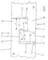
- the projection 6 of the panel 3 and the recess 20 of the panel 2 form, as can be seen in FIG. 2, a common one Joint G.
- the material removal 12 discussed above on the Top of the projection 6 of the panel 3 and the material removal 24 of the lower wall 21 of the recess 20 of the panel 2 create 2 and 3 freedom of movement when the panels are installed 13 and 25, the joint G in one allow rotation within a small angular range.
- the short straight section 11 is the Top of the projection 6 of the panel 3 with the inside the top wall 22 of the recess 20 of the panel 2 in contact.
- the convex curvature 7 of the projection 6 is on the concave curvature 23 of the lower wall 21 of the recess 20 of the Panels 2 on.
- the side joint joint surfaces 9a facing the upper side and 26 of two connected panels 2 and 3 are always unique to each other.
- Manufacturing tolerances would cause that either the joint faces 9a and 26 exactly against each other abut or projection 6 / recess 20 exactly against each other issue.
- the positive locking profiles are therefore designed that the joint faces 9a and 26 always exactly abut each other and projection 6 / recess 20 for one exact system cannot be moved sufficiently far into each other can.
- the manufacturing tolerances are of the order of magnitude of hundredths of a millimeter are also nestled Projection 6 / recess 20 almost exactly against each other.
- Panels 2 and 3 with the complementary positive locking profiles described 4 and 5 can be done in different ways fasten to each other.
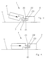
- 3 is a panel 2 with a Cutout 20 has already been moved, while a second panel 3 with a complementary projection 6 obliquely in the direction of arrow P. inserted vertically into the recess 20 of the first panel 2 becomes. Then the second panel 3 is around the common Center K of the circle sections of the convex curvature 7 of the projection 6 and the concave curvature 23 of the recess 20 rotated until the second panel 3 rests on the underground U.
- FIG. 4 Another type of joining of the panels 2 and 3 discussed is in Fig. 4 shown, after which the first panel 2 with a recess 20 is laid and a second panel 3 with a Projection 6 in the installation plane and perpendicular to the form-fitting profiles 4 and 5 is moved in the direction of arrow P until the walls 21 and 22 of the recess 20 are a little elastic expand and the convex curvature 7 of the projection 6 the undercut at the front end of the concave curvature 23 has overcome the lower wall and the final laying position is reached.
- Panels 2 and 3 are on an irregular surface U.
- the first panel 2 with the form-fitting profile 5 is on it Top has been charged. This makes the narrow side of the Panels 2 with the form-fitting profile 5 have been raised. That with the positive locking profile 5 connected positive locking profile 4 of the panel 3 has also been raised.
- Through the joint G results there is a kink between the two panels 2 and 3.
- the freedom of movement 13 and 25 create space for the rotary movement of the joint.
- the joint formed from both panels 2 and 3 G is moved upwards a little from the installation level Service.
- the freedom of movement 13 is complete for the rotation have been exploited so that the top of the projection 6 of the Panels 3 in the area of material removal 12 on the inside the wall 22 of the panel 2 rests.
- the liaison office is flexible in itself and forces the positive locking profiles involved 4 and 4 no unnecessary and material-fatiguing bending stress on.
- FIG. 6 shows an articulated movement of two installed panels 2 and 3 shown in the opposite direction of rotation.
- the on panels 2 and 3 laid on an irregular underground are buckled down.
- the construction is designed that when the connection point bends out of the Laying level towards the underground U is a much stronger elastic Deformation of the lower wall 21 of the recess 20 occurs than when bending from the installation level above.
- the point of this measure is that the panels 2 and 3 buckled downwards after relief do not return to the installation level due to their own weight can.
- the stronger elastic deformation of the bottom wall 21 of the recess 20, however, produces a tension force, the panels 2 and 3 immediately after relief resiliently moved back to the installation level.
- the form-fitting profiles 4 and 5 described are present molded in one piece on the narrow sides of panels 2 and 3. This is preferably done by a so-called formatting process, in which the positive locking profiles 4 and 5 with several milling tools connected in series mill the shape of the narrow sides of panels 2 and 3.
- the Panels 2 and 3 of the described embodiment exist essentially of an MDF board with a thickness of 8 mm.
- the top of the MDF board is wear-resistant and decoratively coated.
- At the bottom is a so-called Counteracting layer attached, which is from the top coating caused residual stresses.
- Fig. 7 shows two panels 2 and 3 laid State, wherein a fastening system 1 with a soft elastic curing filler 30 is used.
- the filler 30 is between all adjacent parts of the provided positively connected narrow sides.
- the top joint 31 is closed with the filler, so that no moisture and no dirt can penetrate.
- this causes two panels 2 to be bent and 3 self-deforming filler 30 due to its elasticity a reset of the panels 2 and 3 in the installation level.
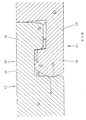
- Fig. 8 shows special holding profiles that are for the short Narrow sides of panels 40 and 41 are provided.
- each Panel faces each other on opposite short narrow sides matching holding profiles 42 and 43 with complementary hook elements 44 and 45 on. This way you can always a right holding profile 42 of a first panel 40 with a Connect the left holding profile 43 of a second panel 41.
- Fig. 8 are the short narrow sides of the panels 40 and 41 in shown in an assembled state.
- the hook element 44 is from a projecting approximately vertically from the narrow side and web 46 arranged on the upper side O of the panel. At the free end of the web 46 there is an underside V of the panels 40 and 41 facing hook projection 47 arranged.
- the hook projection 47 is with a hook projection 48 of the second panel 41 is engaged.
- the hook element 45 of the second panel 41 is formed from a web 49 which of the Narrow side of the second panel 41 protrudes and on the Bottom V of the second panel 41 is arranged.
- the hook projection 48 is arranged at the free end of the web 49 and points to the top side O of the panel 40. The hook projections 47 and 48 and the two panels 40 and 41 are in one another hooked.
- the hook projection 48 of the second panel 41 with the underside Web 49 lies in the assembled state of the second panel 41 on the top web 46 of the first panel 40.
- Embodiment air L1 provided.
- the hook protrusion 48 engage behind holding surfaces 50 and 51 of the Hook projections 47 and 48 such that the hook projections 47 and 48 can only be hooked into one another by elastic deformation are.
- the hook protrusion 48 has an opening formed thereon narrowest point has the width a. This is less than the width b of the hook projection 47 of the first panel 40 its farthest point.
- the hook projections 47 and 48 taper to the webs 46 and 49 there.
- the holding surface 51 of the hook projection 47 of the first panel 40 rounded at the upper and lower ends.
- the hook projections 47 and 48 support in which during a joining movement perpendicular to the laying plane the holding profiles 42 and 43 slowly expanded elastically become. This facilitates the laying and protects the Holding profiles 42 and 43.
- the adjacent holding surfaces 50 and 51 of the cooperating Panels 40 and 41 therefore nestle in areas together.
- the resulting gaps can be advantageous serve as glue pockets 53.
- a second embodiment of a fastening system is shown in 9 illustrates.
- the embodiment according to FIG. 9 differs from 8 in that the one of the two pairs of web 49 / hook projection 47 respectively Web 46 / hook projection 48, which abuts each other, and the those that have an air gap L1 have changed.
- the basic function of the fastening system remains equal. This in turn results in a clear investment of the Hook projection 47 and a gapless surface of the floor covering.
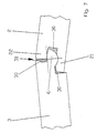
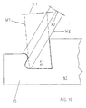
- FIG. 10 shows a schematic illustration of a panel 41 with a holding profile 43 according to the invention entered as the undercut contour of the hook projection 48 using two cutting tools W1 and W2, which rotate about the axes X1 and X2, can be produced.
- the Tools W1 and W2 create a recess 57 in the complementary hook projection of another panel (not shown) can be snapped into place.
- FIG. 11 is an alternative embodiment with special complementary holding profiles 60 and 61 to the short narrow sides of panels 62 and 63 can be seen.
- hook elements 64 and 67 are provided which, like the foregoing Embodiments have webs and hook projections.
- the embodiment according to FIG. 11 is constructed in such a way that the end face 75 of the underside hook element 64 of the second panel 63 at its free end a protruding locking element 65 has that in an undercut recess 66 of the top hook element 67 of the first panel 62 attacks.
- the hook elements 64 and 67 can be easily Lock pressure and into each other under elastic deformation.
- the panels 62 and 63 are inserted into the recess 66 engaging locking element 65 locked perpendicular to the installation plane.
- the locking of the panels 62 and 63 against pulling apart in the longitudinal direction is by holding surfaces 68 and 69 accomplished that on hook projections 70 and 71 of the hook elements 64 and 67 are provided.
- the protruding locking element 65 of the second panel 63 is shown in FIG the embodiment shown as a bead, the extends over the entire length of the narrow side.
- the undercut recess 66 of the first panel 62 is as elongated throat, which formed the bead in the assembled Condition. Bead and throat can be passed through milling so-called formatting in one production run. To join panels 62 and 63, bead and throat must be used with elastic deformation of the hook elements 64 and 67 be joined together.
- FIG. 11 A further embodiment is shown in FIG is based on the embodiment according to FIG. 11. Same features these two figures have the same reference numerals Mistake.
- the 12 constructed so that the End face 72 of the top hook element 67 of the first Panels 62 have a protruding locking element at their free end 73, which in an undercut recess 74 of the hook element 64 on the underside of the second panel 63 engages.
- something must greater pressure are exerted than in the embodiment 11.
- the panels 62 and 63 are by the in Recess 66 engaging locking element 65 and the additional in the recess 74 engaging locking element 73 firmer locked than in the embodiment of FIG. 11.
- Locking elements 65 repective 73 of the panels 62 and 63 are designed as beads that extend over the entire length extend a narrow side.
- a protruding nose is provided with a slope be (not shown)
- the slope of the nose oriented so is that with increasing progress of the joining process a gentle widening of the corresponding hook element is accomplished.
- the undercut recesses 66 and 74 of the panels 62 and 63 are designed as elongated throats, which take up the beads in the assembled state. Bead and throat can be formatted by so-called mill a production pass.
- the exemplary embodiments also differ of Figures 11 and 12 in the interaction of the webs 46, 49 with the hook projections 71, 70.
- the Web 46 on the hook projection 71 and is between the hook projection 70 and the web 49 air is provided.
- 12 is air between the web 46 and the hook projection 71 and the hook projection 70 bears against the web 49.
Abstract
Description
Die Erfindung betrifft ein Paneel sowie ein Befestigungssystem für Paneele mit an den Schmalseiten der Paneele angeordneten Halteprofilen, insbesondere für Fußbodenpaneele, die auf einem Untergrund zu verlegen sind, wobei das Halteprofil einer langen Schmalseite und das Halteprofil der gegenüberliegenden Schmalseite sowie die Halteprofile der beiden übrigen kurzen Schmalseiten eines Paneels derart zueinanderpassen, daß an den freien Schmalseiten eines verlegten Paneels weitere Paneele befestigbar sind, wobei zumindest die Halteprofile der langen Schmalseiten der Paneele als einander zugeordnete Formschlußprofile ausgebildet und die Paneele durch eine drehende Fügebewegung aneinander befestigbar sind, daß das Formschlußprofil einer der langen Schmalseiten eines Paneels eine Aussparung und die gegenüberliegende Schmalseite dieses Paneels einen dazu passenden Vorsprung aufweist, daß die dem Untergrund zugewandte Wand der Aussparung innenseitig einen Querschnitt mit einer konkaven Wölbung aufweist und, daß das zugeordnete Formschlußprofil der gegenüberliegenden Schmalseite des Paneels einen Vorsprung aufweist, der an seiner dem Untergrund zugewandten Unterseite einen Querschitt mit einer konvexen Wölbung aufweist, und daß die konvexe Wölbung des Vorsprungs und die konkave Wölbung der Aussparung im wesentlichen komplementär ausgebildet sind.The invention relates to a panel and a fastening system for panels with arranged on the narrow sides of the panels Retaining profiles, especially for floor panels on a Are to be laid underground, the holding profile of a long Narrow side and the holding profile of the opposite Narrow side as well as the holding profiles of the other two short ones Narrow sides of a panel fit together so that on the free narrow sides of a laid panel further panels are attachable, at least the holding profiles of the long Narrow sides of the panels as mutually associated positive locking profiles trained and the panels by a rotating joining movement are attachable to each other that the positive profile one of the long narrow sides of a panel has a recess and the opposite narrow side of this panel has a matching projection that the underground facing wall of the recess inside a cross section has a concave curvature and that the associated Positive locking profile on the opposite narrow side of the panel has a protrusion which is on its surface facing bottom a cross section with a convex Has curvature, and that the convex curvature of the projection and the concave curvature of the recess essentially are complementary.
Befestigungssysteme der genannten Art halten Paneele im fertig verlegten Zustand durch eine formschlüssige Verbindung zusammen. Insbesondere bei schwimmend auf einem Untergrund verlegten Fußbodenpaneelen verhindert eine formschlüssige Verbindung zwischen den Paneelen das Entstehen von Fugen, die beispielsweise durch Wärmeausdehnung bzw. Verkürzung bei Temperaturabfall entstehen können.Fastening systems of the type mentioned keep panels ready installed condition by a positive connection. Especially when laid floating on a surface Floor panels prevent a positive connection between the panels the creation of joints, for example through thermal expansion or shortening when the temperature drops can arise.
Aus dem deutschen Gebrauchsmuster G 79 28 703 U1 ist ein gattungsgemäßes Befestigungssystem bekannt. Fußbodenpaneele mit einem derartigen Formschlußprofil lassen sich sehr leicht durch eine drehende Fügebewegung miteinander verbinden. Die Verbindung eignet sich prinzipiell auch für eine Mehrfachverlegung. Die entstehende formschlüssige Verbindung ist sehr steif und verhindert dadurch die Entstehung von Fugen sehr zuverlässig.From the German utility model G 79 28 703 U1 is a generic Fastening system known. Floor panels with such a positive locking profile can be very easily connect with each other by a rotating joining movement. The In principle, connection is also suitable for multiple laying. The resulting positive connection is very good stiff and thus prevents the formation of joints reliable.
Nachteiligerweise eignet sich das bekannte Befestigungssystem nur für besonders ebene Untergründe. Bei unregelmäßigen, rauhen und gewellten Untergründen schmiegt sich ein Paneelfußboden mit dem bekannten Befestigungssystem nur sehr schlecht an die Form des unregelmäßigen Untergrunds an. Wird beispielsweise ein Paneel, das im verlegten Zustand durch die benachbarten Paneele mit etwas Luft über einem gewellten Untergrund gehalten ist bei Belastung auf den Untergrund gedrückt, so biegen sich aneinander befestigte Fußbodenpaneele durch. Diese Durchbiegung beansprucht insbesondere die Verbindungsstellen mit den ineinandergreifenden Formschlußprofilen. Je nach Belastung werden die miteinander verbundenen Paneele nach unten oder oben durchgeknickt und dabei aus der normalen Verlegeebene herausgedrückt. Wegen der hohen Steifigkeit der Verbindung tritt eine hohe Belastung in den schwachen Querschnitten der Formschlußprofile auf, die dadurch sehr schnell beschädigt werden. Die Schädigung schreitet schnell voran bis ein Vorsprung oder eine Aussparungswand bricht.The known fastening system is disadvantageously suitable only for particularly flat surfaces. With irregular, rough and corrugated surfaces nestle a panel floor with the known fastening system only very poorly the shape of the irregular surface. For example a panel that is laid by the neighboring ones Panels with some air over a corrugated surface is pressed on the ground when loaded, so bend attached floor panels. This Deflection stresses the connection points in particular with the interlocking interlocking profiles. Depending on the load the interconnected panels are facing down or buckled up and from the normal installation level pushed out. Because of the high rigidity of the connection high stress occurs in the weak cross sections of the Form-fitting profiles, which damage very quickly become. The damage progresses quickly to a head start or a recess wall breaks.
Auch bei einem ebenen Untergrund können Paneele eine wechselnde Durchbiegung erleiden dann nämlich, wenn auf dem Untergrund eine weiche Zwischenlage, beispielsweise eine trittschalldämmende Folie oder dergleichen verlegt ist. An einer belasteten Stelle wird die Zwischenlage eingedrückt und die Paneele knicken an ihren Verbindungsstellen durch.Even on a flat surface, panels can change Deflection occurs when on the ground a soft intermediate layer, for example an impact sound absorbing one Foil or the like is laid. On a burdened The intermediate layer is pressed in and the panels buckle at their junctions.
Der Erfindung liegt daher die Aufgabe zugrunde, das bekannte Befestigungssystem so weiterzubilden, daß die Steifigkeit der Verbindung zweier ineinandergefügter Formschlußprofile an die Beanspruchung angepaßt ist die die Verbindungen bei Verlegung der Paneele auf einem unregelmäßigem Untergrund zu ertragen haben.The invention is therefore based on the object, the known Fixing system so that the rigidity of the Connection of two interlocking positive locking profiles to the The connections are adapted to the stress when laying to endure the panels on an irregular surface to have.
Erfindungsgemäß wird die Aufgabe dadurch gelöst, daß die Formschlußprofile der langen Schmalseiten zweier Paneele im verlegten Zustand zweier Paneele ein gemeinsames Gelenk bilden, daß die dem Untergrund abgewandte Oberseite des Vorsprungs eines Paneels eine schräge Materialabtragung aufweist, die sich bis zum freien Ende des Vorsprungs erstreckt, daß die Dicke des Vorsprungs durch die Materialabtragung zum freien Ende hin zunehmend verringert ist, und daß durch die Materialabtragung ein Bewegungsfreiraum für das gemeinsame Gelenk geschaffen ist.According to the invention the object is achieved in that the positive-locking profiles the long narrow sides of two panels in the laid Condition of two panels form a joint, that the top of the projection facing away from the ground of a panel has an oblique material removal that extends to the free end of the projection that the Thickness of the projection due to the removal of material to the free End is increasingly reduced, and that through the removal of material a freedom of movement for the joint is created.
Die neue Konstruktion gestattet eine gelenkige Bewegung zweier miteinander verbundener Paneele. Insbesondere können zwei miteinander verbundene Paneele an der Verbindungsstelle nach oben durchgeknickt werden. Liegt beispielsweise ein Paneel auf einem Untergrund mit einer Erhebung, so daß eine Schmalseite des Paneels bei Belastung auf den Untergrund gedrückt wird und sich die gegenüberliegende Schmalseite aufwärts wippt, so wird ein an der aufwärts wippenden Schmalseite befestigtes zweites Paneel mit nach oben bewegt. Die dabei wirkenden Biegekräfte schädigen die schmalen Querschnitte der Formschlußprofile jedoch nicht. Statt dessen findet eine Gelenkbewegung statt. Ein mit dem vorgeschlagenen Befestigungsystem verlegter Fußboden weist somit eine an unregelmäßige rauhe oder gewellte Untergründe angepaßte Nachgiebigkeit auf. Das Befestigungsystem eignet sich daher besonders gut für Paneele zur Renovierung unregelmäßiger Fußböden in Altbauten. Selbstverständlich ist es auch für eine Verlegung von Paneelen auf einer weichen Zwischenlage besser geeignet als das bekannte Befestigungssystem. The new construction allows articulated movement of two interconnected panels. In particular, two interconnected panels at the junction be buckled at the top. For example, there is a panel a subsurface with an elevation so that a narrow side of the panel is pressed onto the surface under load and the opposite narrow side seesaws upwards a second attached to the upward rocking narrow side Panel with moved up. The bending forces that act damage the narrow cross-sections of the interlocking profiles However not. Instead, a joint movement takes place. A floor laid with the proposed fastening system thus shows an irregular rough or wavy Elasticity adjusted to the substrate. The fastening system is therefore particularly suitable for renovation panels irregular floors in old buildings. Of course it is also for laying panels on one soft liner is more suitable than the known fastening system.
Die Konstruktion trägt dem Prinzip der "angepaßten Verformbarkeit" Rechnung. Dieses Prinzip beruht auf der Erkenntnis, daß sehr steife und dadurch vermeintlich stabile Verbindungsstellen hohe Kerbspannungen verursachen und dadurch leicht versagen. Um dies zu vermeiden, sollen Bauteile so gestaltet sein, daß sie eine auf den Einsatzzweck abgestimmte Nachgiebigkeit oder "angepaßte Verformbarkeit" aufweisen und auf diese Weise Kerbspannungen vermindert werden.The construction is based on the principle of "adapted deformability" Bill. This principle is based on the knowledge that very stiff and therefore supposedly stable connection points cause high notch stresses and therefore easily fail. To avoid this, components should be designed so that they are compliant to the purpose or "adapted deformability" and in this way Notch stresses can be reduced.
Darüber hinaus sind die Formschlußprofile so ausgelegt, daß eine Belastung der Oberseite der Fußbodenpaneele im verlegten Zustand von der oberseitigen Wand der Aussparung eines ersten Paneels in den Vorsprung des zweiten Paneels und von dem Vorsprung des zweiten Paneels in die unterseitige Wand des ersten Paneels übertragen wird. Die Wände der Aussparung des ersten Paneels haben in verlegtem Zustand Kontakt mit der Ober- und Unterseite des Vorsprungs des zweiten Paneels. Die obere Wand der Aussparung hat jedoch nur in einem kurzen Bereich an dem freien Ende der oberen Wand der Aussparung Kontakt mit dem Vorsprung des zweiten Paneels. Auf diese Weise gestattet die Konstruktion unter geringer elastischer Verformung der Wände der Aussparung eine Gelenkbewegung zwischen dem Paneel mit der Aussparung und dem Paneel mit dem Vorsprung. Auf diese Weise ist die Steifigkeit der Verbindung bestens angepaßt an eine unregelmäßige Unterlage, welche zwangsläufig zu einer Knickbewegung zwischen aneinander befestigten Paneelen führt.In addition, the positive locking profiles are designed so that a load on the top of the floor panels in the installed Condition of the top wall of the recess of a first Panels in the projection of the second panel and from the projection of the second panel in the underside wall of the first Panels is transferred. The walls of the recess of the first When installed, panels have contact with the top and Bottom of the protrusion of the second panel. The top wall However, the recess has only a short area on the free end of the top wall of the recess contact with the Protrusion of the second panel. In this way, the Construction with little elastic deformation of the walls the recess a joint movement between the panel with the Recess and the panel with the tab. In this way the rigidity of the connection is best adapted to one irregular pad, which inevitably leads to a kinking movement between panels fastened together.
Ein weiterer Vorteil wird darin gesehen, daß sich Paneele mit dem erfindungsgemäßen Befestigungssystem besser für eine mehrfache Verlegung eignen als Paneele mit dem bekannten Befestigungssystem, weil die Paneele mit dem erfindungsgemäßen Befestigungssystem auch nach langem Gebrauch auf einem unregelmäßigen Untergrund keine Vorschädigung der Formschlußprofile aufweisen. Die Formschlußprofile sind formstabil und haltbar. Sie können wesentlich länger benutzt und während ihres Lebenszyklus häufiger wiederverlegt werden. Another advantage is the fact that panels are the fastening system according to the invention better for a multiple Laying are suitable as panels with the known fastening system, because the panels with the fastening system according to the invention even after long use on an irregular No pre-damage to the interlocking profiles exhibit. The form-fitting profiles are dimensionally stable and durable. They can be used much longer and during their life cycle be relocated more often.
Vorteilhaft bilden die konvexe Wölbung des Vorsprungs und die konkave Wölbung der Aussparung im wesentlichen je einen Kreisabschnitt, wobei im verlegten Zustand der Kreismittelpunkt der Kreisabschnitte auf der Oberseite des Vorsprungs oder unterhalb der Oberseite des Vorsprungs angeordnet ist. Im letzteren Fall liegt der Kreismittelpunkt innerhalb des Querschnitts des Vorsprungs.Advantageously, the convex curvature of the projection and the concave curvature of the cutout, essentially a segment of a circle, where in the installed state the center of the circle Circular sections on the top of the tab or below the top of the projection is arranged. In the latter In this case, the center of the circle lies within the cross section of the Projection.
Durch diese einfache Konstruktion ergibt sich ein Gelenk, dessen konvexe Wölbung des Vorsprungs ähnlich einer Gelenkkugel und die konkave Wölbung der Aussparung ähnlich einer Gelenkpfanne ausgebildet sind, wobei im Unterschied zu einem Pfannengelenk selbstverständlich nur eine ebene Drehbewegung aber keine sphärische Drehbewegung möglich ist.This simple construction results in a joint, the convex curvature of the projection similar to a joint ball and the concave curvature of the recess similar to an acetabular cup are trained, in contrast to one Of course, the socket joint only has a flat rotary movement but no spherical rotation is possible.
In einer günstigen Weiterbildung ist derjenige Punkt der konvexen Wölbung an der Unterseite des Vorsprungs, der im verlegten Zustand am weitesten in Richtung der Unterlage hervorsteht, so angeordnet, daß er sich etwa unterhalb der Oberkante des Paneels befindet. Dadurch ergibt sich ein im Verhältnis zur Gesamtdicke des Paneels relativ starker Querschnitt für den Vorsprung. Außerdem bietet die konkave Wölbung der Aussparung eine ausreichend große Hinterschneidung für die konvexe Wölbung des Vorsprungs, so daß diese durch in der Verlegeebene wirkende Zugkräfte kaum auseinander zu bewegen sind.In a favorable further education, the point is the convex one Bulge at the bottom of the protrusion, which is misplaced Most protruding towards the surface, arranged so that it is approximately below the top edge of the panel. This results in a ratio to the total thickness of the panel relatively strong cross section for the lead. In addition, the concave curvature offers the recess a sufficiently large undercut for the convex Curvature of the projection, so that this through in the installation level acting tensile forces can hardly be moved apart.
Die Gelenkeigenschaften zweier miteinander verbundener Paneele
können weiter verbessert werden, wenn die dem Untergrund zugewandte
Wand der Aussparung eines Paneels auf ihrer Innenseite
eine schräge Materialabtragung aufweist, die sich bis zum
freien Ende der Wand erstreckt und die Wandstärke dieser Wand
zum freien Ende zunehmend dünner ist. Dabei ist durch die
Materialabtragung im verlegten Zustand zweier Paneele ein
Bewegungsfreiraum für das gemeinsame Gelenk geschaffen. Mit
dieser Verbesserung wird der Anteil an elastischer Verformung
der Wände der Aussparung während der Durchbiegung der verlegten
Paneele nach oben weiter verringert.
Zweckmäßig ist es auch, wenn die Aussparung eines Paneels zur
Verbindung mit dem Vorsprung eines weiteren Paneels durch eine
federelastische Verformung ihrer unteren Wand aufweitbar ist
und, daß die während des Fügens auftretende federelastische
Verformung der unteren Wand im fertig verbundenen Zustand
zweier Paneele wieder zurückgenommen ist. Die Formschlußprofile
werden dadurch nur für den Fügevorgang und während einer
Gelenkbewegung elastisch verformt und unterliegen, wenn sie
nicht belastet sind, keiner elastischen Verspannung.The joint properties of two interconnected panels can be further improved if the wall of the recess of a panel facing the substrate has an inclined material removal on its inside, which extends to the free end of the wall and the wall thickness of this wall is increasingly thinner towards the free end. The removal of material when two panels are installed creates freedom of movement for the joint. With this improvement, the proportion of elastic deformation of the walls of the recess is further reduced during the deflection of the installed panels.
It is also useful if the recess of a panel for connection to the projection of a further panel can be widened by a resilient deformation of its lower wall and that the resilient deformation of the lower wall which occurs during the joining is withdrawn again in the fully connected state of two panels. The form-fitting profiles are thus only elastically deformed for the joining process and during a joint movement and, if they are not loaded, are not subject to any elastic tension.
Nützlich ist es, wenn die Halteprofile der kurzen Schmalseiten eines Paneels ebenfalls als einander zugeordnete Formschlußprofile ausgebildet und durch eine geradlinige Fügebewegung aneinander befestigbar sind.It is useful if the holding profiles of the short narrow sides a panel also as associated form-fitting profiles trained and by a straight-line joining movement are attachable to each other.
Einfacherweise sind die Halteprofile der kurzen Schmalseite eines Paneels mit herkömmlichen etwa rechteckigen Nut- und Federquerschnitten versehen. Diese sind sehr einfach und kostengünstig herstellbar und lassen sich nach dem Fügen der langen Schmalseiten eines Paneels besonders einfach durch seitliches Verschieben ineinander bringen. Auch lassen sich die langen Schmalseiten der Paneele auf ihrer ganzen Länge in paralleler Richtung ineinander schieben.The holding profiles are simply the short narrow side a panel with conventional approximately rectangular groove and Feather cross sections provided. These are very simple and inexpensive producible and can be added after joining the through the long narrow sides of a panel Bring each other sideways. Also can be the long narrow sides of the panels along their entire length in push in parallel direction.
Eine andere Weiterbildung der kurzen Schmalseite eines Paneels sieht vor, daß die Querschnitte der Formschlußprofile im wesentliche den Querschnitten der Formschlußprofile der langen Schmalseiten des Paneels entsprechen. Die Fähigkeit, zwei Paneele auch an deren kurzen Schmalseiten gelenkig zu verbinden, kommt der Nachgiebigkeit eines Fußbodenbelags zugute.Another development of the short narrow side of a panel provides that the cross sections of the form-fitting profiles essentially the cross sections of the form-fitting profiles of the long Correspond to the narrow sides of the panel. The ability to two Also to connect panels in an articulated manner on their short narrow sides, benefits the resilience of a floor covering.
Bevorzugt sind die Formschlußprofile einstückig an den Schmalseiten der Paneele angeformt. Die Paneele lassen sich sehr einfach und mit geringem Verschnitt herstellen.The form-fitting profiles are preferably in one piece on the narrow sides molded on the panels. The panels can be very easy and with little waste.
Besonders geeignet sind die erfindungsgemäßen Formschlußprofile, wenn die Paneele im wesentlichen aus einem MDF (Medium Density Fiberboard), HDF (High Densitiy Fiberboard) oder einem Spanplattenmaterial bestehen. Diese Materialien sind einfach zu bearbeiten und erhalten, beispielsweise durch eine spanende Bearbeitung, eine ausreichende Oberflächenqualität. Außerdem weisen diese Materialien eine hohe Formstabilität der gefrästen Profile auf.The form-fitting profiles according to the invention are particularly suitable, if the panels are essentially made of MDF (medium Density Fiberboard), HDF (High Density Fiberboard) or one Chipboard material exist. These materials are simple to process and receive, for example by cutting Machining, adequate surface quality. Moreover these materials have a high dimensional stability of the milled Profiles on.
Ein weiterer Nutzen ergibt sich, wenn im verlegten Zustand der Paneele die Bewegungsfreiräume für die gemeinsamen Gelenke mit einem weichelastisch aushärtendem Füllstoff versehen sind. Dieser Füllstoff verschließt vorzugsweise alle Fugen und insbesondere die oberseitige Fuge derart, daß keine Feuchtigkeit und kein Schmutz eindringen kann. Bei einer Gelenkbewegung der miteinander verbundenen Paneele wird der weichelastische Füllstoff je nach Drehrichtung der Gelenkbewegung gequetscht oder gedehnt. Er haftet dabei stets an den Kontaktflächen der Schmalseiten der Paneele und nimmt beim Rückgang der Gelenkbewegung wieder seine Ausgangsform an. Der Füllstoff trägt durch seine elastische innere Verformung zur Rückstellung des Gelenks bei.Another benefit arises when the Panels with the freedom of movement for the common joints are provided with a soft elastic hardening filler. This filler preferably closes all joints and in particular the top joint so that no moisture and no dirt can enter. With a joint movement of the interconnected panels become the flexible filler depending on the direction of rotation of the articulated movement or stretched. He always adheres to the contact surfaces of the Narrow sides of the panels and decreases as the joint movement decreases back to its original form. The filler carries through its elastic internal deformation to reset the joint at.
Eine alternative Ausbildung des Befestigungsystems sieht vor, daß eine kurze Schmalseite eines Paneels ein erstes Hakenelement und die gegenüberliegende kurze Schmalseite des Paneels ein zu dem ersten Hakenelement komplementäres zweites Hakenelement aufweist und, daß die Hakenelemente mit Halteflächen versehen sind, durch die die Paneele im montierten Zustand derart gegeneinander gehalten sind, daß sich an den kurzen Schmalseiten eine spaltfrei aneinanderstoßende Oberfläche der Paneele ergibt.An alternative design of the fastening system provides that a short narrow side of a panel is a first hook element and the opposite short narrow side of the panel a second complementary to the first hook element Has hook element and that the hook elements with holding surfaces are provided, through which the panels are assembled are held against each other so that the short narrow sides a gap-free abutting surface the panels result.
Zur Verlegung der Paneele müssen zunächst die Formschlußprofile der langen Schmalseiten der Paneele zusammengefügt werden. Hierfür wird ein Paneel schräg angestellt und mit dem Vorsprung einer langen Schmalseite in die Aussparung der langen Schmalseite eines verlegten Paneels gesteckt. Dadurch bildet sich das gemeinsame Gelenk. Dananch wird das Paneel in der schrägen Position gehalten und in seiner Längsrichtung so weit verschoben, bis es gegen die kurze Schmalseite eines benachbarten Paneels stößt. In dieser Position überlappen sich die Hakenelemente der kurzen Schmalseiten der benachbarten Paneele. Wenn nun das schräg angestellte Paneel mittels des Gelenks heruntergeklappt wird, fügen sich die überlappenden Hakenelemente ineinander. Es ergibt sich ein Hintergreifen, das die Paneele gegen Auseinanderziehen in deren Längsrichtung verriegelt. Durch die Hakenelemente ist ein Maß an Hinterschneidung erreichbar, das bei etwa einem Drittel der gesamten Paneeldicke liegt. Die Art der Verriegelung der kurzen Schmalseiten der Paneele erinnert dabei an sich seitlich hintergreifende Dachpfannen.To install the panels, the form-fitting profiles must first be used the long narrow sides of the panels. For this, a panel is placed at an angle and with the projection a long narrow side in the recess of the long Narrow side of a laid panel inserted. This forms the common joint. Then the panel in the held at an inclined position and so far in its longitudinal direction moved until it was against the short narrow side of an adjacent one Panel bumps. In this position they overlap Hook elements on the short narrow sides of the adjacent panels. If now the inclined panel by means of the joint is folded down, the overlapping hook elements join each other. There is an undertaking that the Panels locked against pulling apart in their longitudinal direction. Due to the hook elements there is a degree of undercut achievable, at about a third of the total panel thickness lies. The way of locking the short narrow sides the panels are reminiscent of those that reach behind one another Roof tiles.
Einfacherweise ist das erste Hakenelement aus einem von der kurzen Schmalseite etwa senkrecht hervorstehenden und an der Paneeloberseite angeordneten Steg gebildet, wobei an dem freiem Ende des Stegs ein zur Unterseite des Paneels weisender Hakenvorsprung angeordnet ist und das zweite Hakenelement aus einem von der gegenüberliegenden kurzen Schmalseite hervorstehenden und an der Unterseite des Paneels angeordneten Steg gebildet, wobei an dem freiem Ende dieses Stegs ein zur Paneeloberseite weisender Hakenvorsprung angeordnet ist.The first hook element is simply one of the short narrow side protruding approximately vertically and on the Panel top arranged web formed, being on the free End of the bridge pointing towards the underside of the panel Hook projection is arranged and the second hook element one protruding from the opposite short narrow side and web arranged on the underside of the panel formed, one at the free end of this web to the top of the panel pointing hook projection is arranged.
Die Oberseite des Paneels geht von dem Bereich mit der Dicke des kompletten Paneels mit einer Dickenabstufung über in den Steg. Der Steg weist etwa eine Dicke auf, die einem Drittel der Paneeldicke entspricht. Das gleiche gilt für die Unterseite des Paneels. Dem Hakenelement der Oberseite gegenüberliegend geht der unterseitige Steg von dem Bereich der kompletten Dicke des Paneels mit einer Dickenabstufung über in den Steg, der ebenfalls etwa ein Drittel der Dicke des Paneels aufweist. Die Stege sowie die Hakenvorsprünge sind somit relativ massiv ausgebildet. Daher ergibt sich eine Verbesserung der Festigkeit und Haltbarkeit für das erfindungsgemäße Befestigungssystem.The top of the panel goes from the area with the thickness of the complete panel with a thickness gradation across in Web. The web has a thickness of about a third corresponds to the panel thickness. The same applies to the bottom of the panel. Opposite the top hook element the underside web goes from the area of the complete Thickness of the panel with a gradation across in the web, which is also about a third of the thickness of the panel. The webs and the hook projections are therefore relatively solid educated. Therefore, there is an improvement in strength and durability for the fastening system according to the invention.
Vorteilhaft liegt der Hakenvorsprung des unterseitigen Stegs im montierten Zustand eines Paneels an dem oberseitigen Steg eines zweiten Paneels an. Außerdem ist zwischen dem Hakenvorsprung des oberseitigen Stegs des zweiten Paneels und dem unterseitigen Steg des ersten Paneels Luft vorgesehen.The hook projection of the underside is advantageously located Bridge in the assembled state of a panel on the top Web of a second panel. Also, between that Hook projection of the top web of the second panel and Air is provided on the underside web of the first panel.
Selbstverständlich ist dies auch umkehrbar, so daß zwischen dem Hakenvorsprung des unterseitigen Stegs des ersten Paneels und dem oberseitigen Steg des zweiten Paneels Luft vorgesehen ist. Es kommt darauf an, daß stets eine Paarung Steg/Hakenvorsprung gefügter Hakenelemente im montierten Zustand eindeutig aneinander anliegen und die andere Paarung Steg/Hakenvorsprung derselben Hakenelemente Luft aufweist. Wäre das Befestigungssystem so konstruiert, daß stets beide Paarungen Steg/Hakenvorsprung aneinander anliegen, so würden durch Toleranzen bei der Fertigung der Halteprofile keine eindeutige Anlage erreicht und mal die eine und mal die andere Paarung Steg/Hakenvorsprung anliegen.Of course, this is also reversible, so that between the hook projection of the underside web of the first panel and air is provided on the upper web of the second panel is. It is important that there is always a pairing Bridge / hook projection of assembled hook elements in the assembled state clearly abut each other and the other pairing Web / hook projection of the same hook elements has air. Would the fastening system be designed so that both Pairings of web / hook projection abut each other, so would due to tolerances in the manufacture of the holding profiles clear system achieved and sometimes one and sometimes the other Pair the web / hook projection.
Eine Weiterbildung des Befestigungssystems sieht vor, daß die Halteflächen der Hakenvorsprünge sich derart hintergreifen, daß sie nur durch elastische Verformung ineinander verhakbar sind. Auf diese Weise kann verhindert werden, daß die Hakenelemente beispielsweise wegen eines unebenen Untergrunds bei Belastung auseinanderbewegt werden können. Bei einer Belastung eines Paneels wird das verbundene Paneel mit dem belasteten Paneel in die gleiche Richtung bewegt. Die Fügestelle bleibt zusammen.A further development of the fastening system provides that the holding surfaces of the hook projections engage behind in such a way that they can only be hooked into one another by elastic deformation are. In this way, the Hook elements, for example due to an uneven surface can be moved apart when loaded. With a load of a panel, the connected panel is loaded with the Panel moved in the same direction. The joint stay together.
Einfacherweise sind die Halteflächen der Hakenvorsprünge schräg gestellt und verjüngen sich die Hakenvorsprünge von ihren freien Enden zu den Stegen hin. Weiterhin liegen die Halteflächen komplementärer Hakensprünge zumindest bereichsweise aneinander an. Hierbei handelt es sich um eine einfache Gestaltung der mit einer Hinterschneidung versehenen Hakenvorsprünge, weil als Hinterschneidung eine einfach herstellbare ebene Haltefläche vorgesehen ist.The holding surfaces are simply the hook projections slanted and the hook projections of their free ends towards the webs. Furthermore, the Holding surfaces of complementary hook jumps at least in some areas to each other. This is a simple one Design of the hook projections provided with an undercut, because as an undercut an easy to manufacture flat holding surface is provided.
Ein weiterer Nutzen ergibt sich, wenn die Stirnseite des oberseitigen Hakenvorsprungs des einen Paneels im montierten Zustand zumindest in dem Bereich der Paneeloberseite an dem zweiten Paneel anliegt und zwischen dem unterseitigen Hakenvorsprung des zweiten Paneels und der Stirnseite des ersten Paneels Luft vorgesehen ist. Diese Maßnahme dient wiederum dazu, durch die konstruktive Gestaltung eine stets eindeutige Anlage zweier verbundener Paneele zu schaffen.Another benefit is when the front of the top hook projection of one panel in the assembled Condition at least in the area of the top of the panel on the second panel rests and between the hook projection on the underside of the second panel and the face of the first Panel air is provided. This measure in turn serves in addition, through the constructive design an always clear To create two connected panels.
An der Unterseite der Paneele, die auf eine Unterlage, beispielsweise einen Estrich, aufgelegt wird, kann im Bereich der Fügestelle ein Luftspalt zwischen den Paneelen geduldet werden.At the bottom of the panels, for example, on a base a screed, can be placed in the area of An air gap between the panels can be tolerated.
Eine alternative Ausführungsform mit Hakenelementen an den kurzen Schmalseiten des Paneels ist so konstruiert, daß wenigstens eine der Stirnseiten eines der Hakenelemente der Paneele an ihrem freien Ende ein vorstehendes Rastelement aufweist, das in eine hinterschnittene Vertiefung des anderen Hakenelements des Paneels greift. Diese Konstruktion hat sich als besonders gut handhabbar herausgestellt, weil sich die Halteprofile mit leichtem Druck und unter elastischer Verformung ineinander verrasten lassen. Außerdem weisen die Halteelemente eine gute Verschleißfestigkeit auf, was eine Mehrfachverlegung begünstigt. Die Verschleißfestigkeit ist deshalb gut, weil verschiedene Arretierfunktionen von verschiedenen Halteelementbereichen ausgeübt werden und die Beanspruchung des Halteelements so verteilt auftritt. Die Paneele werden zum Beispiel durch das Rastelement und die Vertiefung senkrecht zur Verlegeebene arretiert. Die Arretierung der Paneele gegen Auseinanderziehen in deren Längsrichtung wird hingegen durch die Halteflächen der Hakenvorsprünge bewerkstelligt.An alternative embodiment with hook elements on the short narrow sides of the panel is constructed so that at least one of the end faces of one of the hook elements of the panels has a projecting locking element at its free end, that in an undercut recess of the other hook element of the panel. This construction has proven to be turned out to be particularly easy to handle because the holding profiles with light pressure and with elastic deformation snap together. In addition, the holding elements good wear resistance on what a multiple laying favored. The wear resistance is good because different locking functions of different holding element areas are exercised and the stress on the holding element so distributed occurs. The panels, for example through the locking element and the recess perpendicular to Laying level locked. The panels are locked against Pull apart in the longitudinal direction, however, by the holding surfaces of the hook projections accomplished.
Einfacherweise ist das vorstehende Rastelement des ersten Paneels als Wulst ausgebildet, die sich über die gesamte Länge der Schmalseite erstreckt und die hinterschnittene Vertiefung des zweiten Paneels als langgestreckte Kehle ausgebildet, die die Wulst im zusammengefügten Zustand aufnimmt. Zum Fügen müssen Wulst und Kehle unter einer elastischen Verformung der Hakenelemente ineinandergefügt werden.The protruding locking element is simply the first Panels formed as a bead that extends over the entire length the narrow side extends and the undercut recess of the second panel is formed as an elongated throat, which takes up the bead in the assembled state. For joining must bulge and throat under an elastic deformation of the Hook elements can be inserted into one another.
Diese Ausführungsform des Befestigungsystems eignet sich dann, wenn keine Verleimung vorgenommen wird, besonders gut für eine Mehrfachverlegung. Um verlegte Paneele wieder aufzunehmen, hebt man zweckmäßig zuerst eine Reihe nebeneinanderliegender Paneele so an, daß sich diese in dem Gelenk schräg nach oben drehen. Dann werden die Vorsprünge in schräger Richtung aus den Aussparungen, herausgezogen und das Gelenk auseinandergenommen. Die Paneele sind dann nur noch an den kurzen Schmalseiten verbunden. Es empfiehlt sich die ineinandergefügten Halteelemente der kurzen Schmalseiten in ihrer Längserstrekkung auseinanderzuziehen, um auf diese Weise bei der Zerlegung eine materialermüdende Verformung der Hakenelemente zu vermeiden.This embodiment of the fastening system is then suitable if no gluing is done, especially good for one Multiple laying. To resume installed panels, it is advisable to first lift a row of adjacent ones Panels so that they are inclined upwards in the joint rotate. Then the protrusions are slanted out the recesses, pulled out and the joint disassembled. The panels are then only on the short narrow sides connected. It is recommended that the nested Holding elements of the short narrow sides in their longitudinal extent pull apart to this way when disassembling to avoid material-tiring deformation of the hook elements.
Eine weitere Verbesserung wird darin gesehen, daß die im montierten Zustand zweier Paneele mit Luft versehenen Bereiche Leimtaschen bilden. Neben der Verwendung des vorgeschlagenen Befestigungssystems für eine leimfreie Verlegung von Fußbodenpaneelen eignet es sich besonders gut für eine Verbindung mit Leim. Zu diesem Zweck können diejenigen Stellen der Halteprofile, die mit Leim versehen sein müssen, beispielsweise in einer Gebrauchsanweisung oder durch Markierungen an dem Halteprofil selbst gekennzeichnet sein. Auf diese Weise kann der Benutzer sehr genau dort Leim anbringen, wo sich im montierten Zustand zweier Paneele Leimtaschen ergeben.Another improvement is seen in the fact that the Assembled state of two panels with air areas Form glue pockets. In addition to using the proposed Fastening system for glue-free laying of floor panels it is particularly suitable for a connection with Glue. For this purpose, those points of the holding profiles, which must be provided with glue, for example in instructions for use or by markings on the holding profile be marked yourself. In this way, the Apply glue very precisely to the user where it is installed Condition of two panels of glue pockets.
In den überwiegenden Anwendungsfällen der Fußbodenpaneele wird die verleimte Verlegung als zweckmäßigste Verlegeart angesehen. Dies, weil die Haltbarkeit der Paneele deutlich verbessert wird. Die Verleimung der Halteprofile bewirkt, daß ein Eindringen von Schmutz und Feuchtigkeit in die Fugen nahezu verhindert wird. Die Feuchtigkeitsaufnahme und das Quellen der Paneele im Fügebereich der Halteprofile wird dadurch minimiert.In the predominant applications of floor panels the glued installation is considered the most expedient type of installation. This is because the durability of the panels is significantly improved becomes. The gluing of the holding profiles causes a Virtually penetration of dirt and moisture into the joints is prevented. The moisture absorption and swelling of the This minimizes panels in the joining area of the holding profiles.
Selbstverständlich können Anwendungsfälle vorkommen, für die eine leimfreie Verlegung zu bevorzugen ist. Beispielsweise dann, wenn ein Fußbodenbelag häufig verlegt wieder aufgenommen und neu verlegt werden muß, z.B. bei Fußböden im Messebau. Of course, there may be use cases for which a glue-free installation is preferable. For example then when a floor covering is frequently resumed and has to be relocated, e.g. for floors in exhibition stand construction.
Bevorzugt sind die Paneele aus einem beschichteten Trägerstoff gebildet und die Halteprofile einstückig an den Schmalseiten der Paneele angeformt. Es hat sich erwiesen, daß die Festigkeit moderner Trägerstoffe, wie beispielsweise mitteldichter Faserplatten (MDF) oder hochdichter Faserplatten (HDF), die mit einer abriebfesten Nutzschicht versehen sind, sich besonders zum Einsatz des vorgeschlagenen Befestigungssystems eignen. Selbst nach mehrmaliger Verlegung sind die Halteprofile noch so gut in Form, daß eine sichere Verbindung auch auf unebenem Untergrund möglich ist.The panels are preferably made of a coated carrier material formed and the holding profiles in one piece on the narrow sides molded on the panels. It has been shown that the Strength of modern carriers, such as medium density Fiberboard (MDF) or high-density fiberboard (HDF), which are provided with an abrasion-resistant wear layer, are particularly interested in the use of the proposed fastening system suitable. Even after repeated laying, they are Holding profiles so well in shape that a secure connection is also possible on uneven surfaces.
Nachstehend ist die Erfindung beispielhaft in einer Zeichnung dargestellt und anhand der Figuren 1 bis 6 detailliert beschrieben. Es zeigen:
- Fig. 1
- ein Befestigungssystem ausschnittsweise anhand der Querschnitte zweier Paneele vor dem Ineinanderfügen,
- Fig. 2
- das Befestigungssystem gemäß Fig. 1 im aneinander befestigten Zustand,
- Fig. 3
- einen Fügevorgang, bei dem der Vorsprung eines Paneels in Pfeilrichtung in die Aussparung eines zweiten Paneels gesteckt und das erste Paneel nachfolgend mit einer Drehbewegung arretiert wird,
- Fig. 4
- einen weiteren Fügevorgang, bei dem der Vorsprung eines ersten Paneels parallel zur Verlegeebene in die Aussparung eines zweiten Paneels eingeschoben wird,
- Fig. 5
- das Befestigungssystem im befestigten Zustand gemäß Fig. 2, wobei das gemeinsame Gelenk aus der Verlegeebene nach oben bewegt ist und die beiden Paneele einen Knick bilden,
- Fig. 6
- das Befestigungssystem im verlegten Zustand gemäß Fig. 2, wobei das Gelenk aus der Verlegeebene nach unten bewegt ist und die beiden Paneele einen Knick bilden,
- Fig. 7
- ein Befestigungssystem im verlegten Zustand zweier Paneele mit einem Füllstoff zwischen den Formschlußprofilen der Schmalseiten.
- Fig. 8
- besondere Halteprofile für die kurzen Schmalseiten eines Paneels im ineinandergefügten Zustand,
- Fig. 9
- eine weitere Ausführungsform besonderer Halteprofile für die kurzen Schmalseiten eines Paneels im ineinandergefügten Zustand,
- Fig.10
- eine schematische Darstellung eines Halteprofils mit einem unterseitigen Steg sowie einer Darstellung zweier Zerspanungswerkzeuge zur Herstellung der Hinterschneidung,
- Fig.11
- eine dritte Ausführungsform besonderer Halteprofile für die kurzen Schmalseiten eines Paneels im ineinandergefügten Zustand,
- Fig.12
- eine Ausführungsform gemäß Fig. 11, die um ein zusätzliches Rastelement ergänzt ist,
- Fig. 1
- a fastening system in sections based on the cross sections of two panels before joining,
- Fig. 2
- 1 in the attached state,
- Fig. 3
- a joining process in which the projection of a panel is inserted into the recess of a second panel in the direction of the arrow and the first panel is subsequently locked with a rotary movement,
- Fig. 4
- a further joining process in which the protrusion of a first panel is inserted into the recess of a second panel parallel to the laying plane,
- Fig. 5
- 2, the common joint being moved upwards out of the laying plane and the two panels forming a kink,
- Fig. 6
- 2, wherein the joint is moved downward from the laying plane and the two panels form a kink,
- Fig. 7
- a fastening system in the installed state of two panels with a filler between the form-fitting profiles of the narrow sides.
- Fig. 8
- special holding profiles for the short narrow sides of a panel when they are nested,
- Fig. 9
- another embodiment of special holding profiles for the short narrow sides of a panel in the nested state,
- Figure 10
- 1 shows a schematic representation of a holding profile with a web on the underside and a representation of two cutting tools for producing the undercut,
- Figure 11
- a third embodiment of special holding profiles for the short narrow sides of a panel in the nested state,
- Figure 12
- 11, which is supplemented by an additional locking element,
Nach der Zeichnung ist das Befestigungssystem 1 am Beispiel
langgestreckter rechteckiger Paneele 2 und 3 erläutert, von
denen in Fig. 1 ein Ausschnitt dargestellt ist. Das Befestigungssystem
1 weist an den Schmalseiten der Paneele angeordnete
Halteprofile auf, die als komplementäre Formschlußprofile
4 und 5 ausgebildet sind. Die sich gegenüberliegenden Formschlußprofile
eines Paneels sind jeweils komplementär ausgebildet.
Auf diese Weise kann an jedes bereits verlegte Paneel
2 ein weiteres Paneel 3 angebracht werden.According to the drawing, the
Die Formschlußprofile 4 und 5 basieren auf dem Stand der Technik
des deutschen Gebrauchsmusters G 79 28 703 U1. Insbesondere
auf den Formschlußprofilen des Ausführungsbeispiels, das in
den Figuren 14, 15 und 16 sowie in dem zugehörigen Beschreibungsteil
der G 79 28 703 U1 offenbart ist. The
Die erfindungsgemäßen Formschlußprofile sind derart weitergebildet, daß sie eine gelenkige und nachgiebige Verbindung von Paneelen ermöglichen.The form-fitting profiles according to the invention are developed in such a way that they have an articulated and resilient connection of Enable panels.
Eines der Formschlußprofile 4 der vorliegenden Erfindung ist
mit einem von der Schmalseite abstehenden Vorsprung 6 versehen.
Die Unterseite des Vorsprungs 6, die im verlegten Zustand
der Unterlage zugewandt ist, weist zum Zweck der gelenkigen
Verbindung einen Querschnitt mit einer konvexen Wölbung 7 auf.
Die konvexe Wölbung 7 ist in dem komlementären Formschlußprofil
5 drehgelagert. In dem dargestellten Ausführungsbeispiel
ist die konvexe Wölbung 7 kreisabschnittsförmig ausgebildet.
Der unterhalb des Vorsprungs 6 angeordnete Teil 8 der
Schmalseite des Paneels 3, der im verlegten Zustand der Unterlage
zugewandt ist, steht von dem freien Ende des Vorsprungs
6 weiter zurück als der oberhalb des Vorsprungs 6 angeordnete
Teil 9 der Schmalseite. In dem gezeigten Ausführungsbeispiel
tritt der unterhalb des Vorsprungs 6 angeordnete Teil 8 der
Schmalseite etwa doppelt so weit von dem freien Ende des Vorsprungs
6 zurück, wie der oberhalb des Vorsprungs 6 angeordnete
Teil 9 der Schmalseite. Dies liegt darin begründet, daß der
Kreisabschnitt der konvexen Wölbung 7 relativ breit ausgebildet
ist. Dadurch ist der weitest hervorstehende Punkt der
konvexen Wölbung 7 des Vorsprungs 6 so angeordnet, daß er sich
etwa unterhalb der Oberkante 10 des Paneels 3 befindet.One of the
Der oberhalb des Vorsprungs 6 angeordnete Teil 9 der Schmalseite
tritt an der Oberseite des Paneels 3 von der Schmalseite
hervor und bildet eine Fugenstoßfläche 9a. Zwischen dieser
Fugenstoßfläche 9a und dem Vorsprung 6 des Paneels 3 ist der
Teil 9 der Schmalseite zurückgesetzt. Dies gewährleistet, daß
der Teil 9 der Schmalseite immer eine geschlossene oberseitige
Fuge mit der komplementäten Schmalseite eines weiteren Paneels
2 bildet.The
Die der konvexen Wölbung 7 des Vorsprungs 6 gegenüberliegende
Oberseite des Vorsprungs 6 weist ein kurzes gerades Teilstück
11 auf, das im verlegten Zustand ebenfalls parallel zum Untergrund
U angeordnet ist. Von diesem kurzen Teilstück 11 zum
freien Ende hin weist die Oberseite des Vorsprungs 6 eine
schräge Materialabtragung 12 auf, die sich bis zum freien Ende
des Vorsprungs 6 erstreckt.The one opposite the
Das zu dem besprochenen Formschlußprofil 4 komplementäre Formschlußprofil
5 einer Schmalseite weist eine Aussparung 20 auf.
Diese ist im wesentlichen von einer unteren im verlegten Zustand
dem Untergrund U zugewandten Wand 21 und einer oberen
Wand 22 begrenzt. Auf der Innenseite der Aussparung 20 ist die
untere Wand 21 mit einer konkaven Wölbung 23 versehen. Dieser
kommt die Funktion einer Lagerschale zu. Die konkave Wölbung
23 ist ebenfalls kreisabschnittsförmig ausgebildet. Damit die
relativ breite konkave Wölbung 23 an der unteren Wand 21 der
Aussparung 20 Platz findet, steht die untere Wand 21 weiter
von der Schmalseite des Paneels 2 hervor als die obere Wand
22. Die konkave Wölbung 23 bildet an dem freien Ende der unteren
Wand 21 eine Hinterschneidung. Im fertig verlegten Zustand
zweier Paneele 2 und 3 wird diese Hinterschneidung von dem
Vorsprung 6 des zugeordneten Formschlußprofils 4 des benachbarten
Paneels 3 hintergriffen. Das Maß an Hintergreifung, die
Differenz also zwischen der dicksten Stelle des freien Endes
der unteren Wand sowie der Dicke der unteren Wand an dem tiefsten
Punkt der konkaven Wölbung 23 ist so abgestimmt, daß ein
guter Kompromiß zwischen einer gelenkigen Nachgiebigkeit zweier
Paneele 2 und 3 sowie einem guten Halt gegen ein Auseinanderziehen
der Formschlußprofile 4 und 5 in der Verlegeebene
gegeben ist.The form-fitting profile complementary to the form-fitting
Das Befestigungssystem des Standes der Technik gemäß der Figuren 14, 15 und 16 des Gebrauchsmusters G 79 28 703 U1 weist demgegenüber ein erheblich größeres Maß an Hinterschneidung auf. Es ergeben sich dadurch außerordentlich steife Verbindungsstellen, die durch die Beanspruchung auf einem unregelmäßigen Untergrund U hohe Kerbspannungen verursachen.The prior art fastening system according to the figures 14, 15 and 16 of the utility model G 79 28 703 U1 in contrast, a significantly larger degree of undercut on. This results in extremely stiff joints, caused by stress on an irregular Underground U cause high notch tensions.
Die Innenseite der oberen Wand 22 der Aussparung 20 des Paneels
2 ist nach dem Ausführungsbeispiel im verlegten Zustand
parallel zu dem Untergrund U angeordnet.The inside of the
Auf der dem Untergrund U zugewandten unteren Wand 21 der Aussparung
20 des Paneels 2 weist die Innenseite der Wand 21 eine
schräge Materialabtragung 24 auf, die sich bis zum freien Ende
der unteren Wand 21 erstreckt. Dadurch wird die Wandstärke
dieser Wand zum freien Ende zunehmend dünner. Die Materialabtragung
24 schließt sich gemäß dem Ausführungsbeispiel an
das eine Ende der konkaven Wölbung 23 an.On the
Der Vorsprung 6 des Paneels 3 und die Aussparung 20 des Paneels
2 bilden, wie in der Fig. 2 zu sehen, ein gemeinsames
Gelenk G. Die oben besprochene Materialabtragung 12 an der
Oberseite des Vorsprungs 6 des Paneels 3 sowie die Materialabtragung
24 der unteren Wand 21 der Aussparung 20 des Paneels
2 schaffen im verlegten Zustand der Paneele 2 und 3 Bewegungsfreiräume
13 beziehungsweise 25, die dem Gelenk G in einem
kleinen Winkelbereich eine Drehung ermöglichen.The
Im verlegten Zustand steht das kurze gerade Teilstück 11 der
Oberseite des Vorsprungs 6 des Paneels 3 mit der Innenseite
der oberen Wand 22 der Aussparung 20 des Paneels 2 in Kontakt.
Außerdem liegt die konvexe Wölbung 7 des Vorsprungs 6 an der
konkaven Wölbung 23 der unteren Wand 21 der Aussparung 20 des
Paneels 2 an.In the installed state, the short
Die der Oberseite zugewandten seitlichen Fugenstoßflächen 9a
und 26 zweier verbundener Paneele 2 und 3 liegen immer eindeutig
aneinander an. In der Praxis ist eine gleichzeitige
exakte Anlage der konvexen Wölbung 7 des Vorsprung 6 des Paneels
3 an der konkaven Wölbung 23 der Aussparung 20 des Paneels
2 nicht möglich. Fertigungstoleranzen würden dazu führen,
daß entweder die Fugenstoßflächen 9a und 26 exakt aneinander
anliegen oder Vorsprung 6/Aussparung 20 exakt aneinander
anliegen. In der Praxis sind die Formschlußprofile daher so
ausgelegt, daß die Fugenstoßflächen 9a und 26 immer exakt
aneinander anliegen und Vorsprung 6/Aussparung 20 für eine
exakte Anlage nicht genügend weit ineinander bewegt werden
können. Da die Fertigungstoleranzen jedoch in der Größenordnung
von hundertstel Millimeter liegen, schmiegen sich auch
Vorsprung 6/Aussparung 20 nahezu exakt aneinander an.The side joint
Paneele 2 und 3 mit den beschriebenen komplementären Formschlußprofilen
4 und 5 lassen sich auf verschiedene Weisen
aneinander befestigen. Nach Fig. 3 ist ein Paneel 2 mit einer
Aussparung 20 bereits verlegt, während ein zweites Paneel 3
mit einem komplementären Vorsprung 6 in Pfeilrichtung P schräg
stehend in die Aussparung 20 des ersten Paneels 2 eingesteckt
wird. Danach wird das zweite Paneel 3 um den gemeinsamen
Kreismittelpunkt K der Kreisabschnitte der konvexen Wölbung 7
des Vorsprungs 6 und der konkaven Wölbung 23 der Aussparung 20
gedreht, bis das zweite Paneel 3 auf dem Untergrund U aufliegt.
Eine weitere Fügeart der besprochenen Paneele 2 und 3 ist in
Fig. 4 dargestellt, wonach das erste Paneel 2 mit einer Aussparung
20 verlegt ist und ein zweites Paneel 3 mit einem
Vorsprung 6 in der Verlegeebene und senkrecht zu den Formschlußprofilen
4 und 5 in Pfeilrichtung P verschoben wird, bis
sich die Wände 21 und 22 der Aussparung 20 ein wenig elastisch
aufweiten und die konvexe Wölbung 7 des Vorsprungs 6 die Hinterschneidung
an dem vorderen Ende der konkaven Wölbung 23 der
unteren Wand überwunden hat und die endgültige Verlegeposition
erreicht ist.Another type of joining of the
Letztere Fügeart wird bevorzugt für die kurzen Schmalseiten
eines Paneels verwendet, wenn diese mit den gleichen komplementären
Formschlußprofilen 4 und 5 versehen sind, wie die
langen Schmalseiten der Paneele.The latter type of joining is preferred for the short narrow sides
of a panel if used with the same complementary ones
Form-locking
In Fig. 5 ist das Befestigungssystem 1 im Einsatz dargestellt.
Die Paneele 2 und 3 liegen auf einem unregelmäßigen Untergrund
U. Das erste Paneel 2 mit dem Formschlußprofil 5 ist auf seiner
Oberseite belastet worden. Dadurch ist die Schmalseite des
Paneels 2 mit dem Formschlußprofil 5 angehoben worden. Das mit
dem Formschlußprofil 5 verbundene Formschlußprofil 4 des Paneels
3 ist mit angehoben worden. Durch das Gelenk G ergibt
sich ein Knick zwischen den beiden Paneelen 2 und 3. Die Bewegungsfreiräume
13 und 25 schaffen Platz für die Drehbewegung
des Gelenks. Das aus beiden Paneelen 2 und 3 gebildete Gelenk
G ist ein Stück weit aus der Verlegeebene nach oben bewegt
worden. Der Bewegungsfreiraum 13 ist für die Drehung komplett
ausgenutzt worden, so daß die Oberseite des Vorsprungs 6 des
Paneels 3 im Bereich der Materialabtragung 12 an der Innenseite
der Wand 22 des Paneels 2 anliegt. Die Verbindungsstelle
ist in sich nachgiebig und zwingt den beteiligten Formschlußprofilen
4 und 4 keine unnötige und materialermüdende Biegebelastung
auf.5 shows the
Die bei Formschlußprofilen nach dem Stand der Technik früh eintretende Schädigung durch Bruch des Vorsprungs oder der wände der Formschlußprofile wird somit vermieden.The early in form-fitting profiles according to the prior art damage caused by breakage of the projection or the walls of the interlocking profiles is thus avoided.
Ein weiterer Vorteil ergibt sich bei einer Gelenkbewegung
gemäß der Fig. 5. Dieser ist darin zu sehen, daß die beiden
Paneele nach Entlastung durch ihr Eigengewicht wieder in ihre
Verlegeebene zurückfallen. Eine geringe elastische Verformung
der Wände der Aussparung liegt auch in diesem Fall vor. Diese
elastische Verformung unterstützt das Zurückfallen der Paneele
in die Verlegeebene. Es kommt lediglich zu einer sehr geringen
elastische Verformung, weil der Drehpunkt des Gelenks, der
durch die kreisabschnittsförmigen Wölbungen 7 und 23 festgelegt
ist, sich innerhalb des Querschnitts des Vorsprungs 6 des
Paneels 3 befindet.Another advantage arises from a
In Fig. 6 ist eine Gelenkbewegung zweier verlegter Paneele 2
und 3 in entgegengesetzter Drehrichtung dargestellt. Die auf
einem unregelmäßigen Untergrund U verlegten Paneele 2 und 3
sind nach unten durchgeknickt. Die Konstruktion ist so ausgelegt,
daß bei einem Durchknicken der Verbindungsstelle aus der
Verlegeebene zum Untergrund U hin eine deutlich stärkere elastische
Verformung der unteren Wand 21 der Aussparung 20 auftritt
als bei der Durchknickung aus der Verlegeebene nach
oben. Der Sinn dieser Maßnahme ist darin zu sehen, daß die
nach unten durchgeknickten Paneele 2 und 3 nach Entlastung
nicht durch ihr Eigengewicht wieder in die Verlegeebene zurückkehren
können. Die stärkere elastische Verformung der
unteren Wand 21 der Aussparung 20 erzeugt jedoch eine Spannkraft,
die die Paneele 2 und 3 nach Entlastung sofort wieder
federelastisch in die Verlegeebene zurück bewegt.6 shows an articulated movement of two installed
Die beschriebenen Formschlußprofile 4 und 5 sind vorliegend
einstückig an den Schmalseiten der Paneele 2 und 3 angeformt.
Dies geschieht vorzugsweise durch einen sogenannten Formatiervorgang,
bei dem in einem Durchlauf die Formschlußprofile 4
und 5 mit mehreren hintereinandergeschalteten Fräswerkzeugen
die Form der Schmalseiten der Paneele 2 und 3 fräsen. Die
Paneele 2 und 3 des beschriebenen Ausführungsbeispiels bestehen
im wesentlichen aus einer MDF-Platte mit einer Dicke von
8 mm. Die MDF-Platte ist an Ihrer Oberseite verschleißfest und
dekorativ beschichtet. An Ihrer Unterseite ist eine sogenannte
Gegenzugschicht angebracht, die die von der oberseitigen Beschichtung
verursachten Eigenspannungen kompensiert.The form-fitting
Schließlich zeigt Fig. 7 zwei Paneele 2 und 3 im verlegten
Zustand, wobei ein Befestigungsystem 1 mit einem weichelastisch
aushärtenden Füllstoff 30 zum Einsatz kommt. Der Füllstoff
30 ist zwischen allen aneinandergrenzenden Teilen der
formschlüssig verbundenen Schmalseiten vorgesehen. Insbesondere
die oberseitige Fuge 31 ist mit dem Füllstoff verschlossen,
damit keine Feuchtigkeit und kein Schmutz eindringen können.
Außerdem bewirkt der im geknickten Zustand zweier Paneele 2
und 3 in sich verformte Füllstoff 30 durch seine Elastizität
eine Rückstellung der Paneele 2 und 3 in die Verlegeebene.Finally, Fig. 7 shows two
Fig. 8 stellt besondere Halteprofile dar, die für die kurzen
Schmalseiten von Paneelen 40 und 41 vorgesehen sind. Jedes
Paneel weist an gegenüberliegenden kurzen Schmalseiten zueinander
passende Halteprofile 42 und 43 mit komplementären Hakenelementen
44 und 45 auf. Auf diese Weise läßt sich stets
ein rechtes Halteprofil 42 eines ersten Paneels 40 mit einem
linken Halteprofil 43 eines zweiten Paneels 41 verbinden. In
Fig. 8 sind die kurzen Schmalseiten der Paneel 40 und 41 im
ineinandergefügten Zustand dargestellt. Das Hakenelement 44
ist aus einem von der Schmalseite etwa senkrecht hervorstehenden
und an der Paneeloberseite O angeordneten Steg 46 gebildet.
Dabei ist an dem freien Ende des Stegs 46 ein zur Unterseite
V der Paneele 40 und 41 weisender Hakenvorsprung 47
angeordnet. Der Hakenvorsprung 47 ist mit einem Hakenvorsprung
48 des zweiten Paneels 41 in Eingriff. Das Hakenelement 45 des
zweiten Paneels 41 ist aus einem Steg 49 gebildet, der von der
Schmalseite des zweiten Paneels 41 hervorsteht und an der
Unterseite V des zweiten Paneele 41 angeordnet ist. Der Hakenvorsprung
48 ist an dem freien Ende des Stegs 49 angeordnet
und weist zur Paneeloberseite O des Paneels 40. Die Hakenvorsprünge
47 und 48 und der beiden Paneele 40 und 41 sind ineinander
verhakt.Fig. 8 shows special holding profiles that are for the short
Narrow sides of
Der Hakenvorsprung 48 des zweiten Paneels 41 mit dem unterseitigen
Steg 49 liegt im montierten Zustand des zweiten Paneels
41 an dem oberseitigen Steg 46 des ersten Paneels 40 an.
Zwecks einer eindeutigen Anlage ist zwischen dem Hakenvorsprung
47 des oberseitigen Stegs 46 des ersten Paneels 40 und
dem unterseitigen Steg 49 des zweiten Paneels 41 bei der vorliegenden
Ausführungsform Luft L1 vorgesehen.The
Gemäß Fig. 8 hintergreifen sich Halteflächen 50 und 51 der
Hakenvorsprünge 47 und 48 derart, daß die Hakenvorsprünge 47
und 48 nur durch elastische Verformung ineinander verhakbar
sind. Zwischen der Innenfläche 52 des Halteprofils 43 des
zweiten Paneels 41 und der gegenüberliegenden Haltefläche 50
des Hakenvorsprungs 48 ist eine Öffnung gebildet, die an ihrer
engsten Stelle die Weite a aufweist. Diese ist geringer als
die Weite b des Hakenvorsprungs 47 des ersten Paneels 40 an
seiner weitesten Stelle. Durch diese Gestaltung und durch die
elastische Verformung beim Fügen der Hakenvorsprünge 47 und 48
kommt es zu einem Einschnappen der komplementären Hakenvorsprünge
47 und 48 in eine definierte Endlage. In der vorliegenden
Ausführungsform sind die Halteflächen 50 und 51 der
Hakenvorsprünge 47 und 48 einfach gehalten und als schräg
gestellte ebene Flächen ausgebildet. Von den freien Enden
verjüngen sich die Hakenvorsprünge 47 und 48 zu den Stegen 46
und 49 hin. In dem vorliegenden Ausführungsbeispiel ist, wie
in Fig. 8 erkennbar, die Haltefläche 51 des Hakenvorsprungs 47
des ersten Paneels 40 an dem oberen sowie dem unteren Ende abgerundet.
Das gleiche gilt für die Haltefläche 50 des Hakenvorsprungs
48 des zweiten Paneels 41. Dadurch wird das Ineinanderfügen
der Hakenvorsprünge 47 und 48 unterstützt, in dem
während einer senkrecht zur Verlegeebene verlaufenden Fügebewegung
die Halteprofile 42 und 43 langsam elastisch aufgeweitet
werden. Dies erleichtert die Verlegung und schont die
Halteprofile 42 und 43.8 engage behind holding
Die aneinanderliegenden Halteflächen 50 und 51 der zusammenwirkenden
Paneele 40 und 41 schmiegen sich daher bereichsweise
aneinander. Die sich ergebenden Zwischenräume können vorteilhaft
als Leimtaschen 53 dienen.The adjacent holding surfaces 50 and 51 of the cooperating
Weiterhin ist zwischen der Stirnseite 54 des unterseitigen Hakenvorsprungs
48 des zweiten Paneels 41 und der Innenfläche 55
des ersten Paneels 40 Luft L2 vorgesehen. Der sich dadurch
ergebende Zwischenraum kann ebenfalls als Leimtasche 53 dienen.
Gleiches gilt für die Stirnseite 56 des oberseitigen
Hakenvorsprungs 4 des ersten Paneels 40, der im montierten
Zustand zumindest in dem Bereich der Paneeloberseite O und an
dem zweiten Paneel 41 anliegt. Unterhalb der Paneeloberseite
O und zum Inneren der Verbindung hin weitet sich im vorliegenden
Ausführungsbeispiel ein Zwischenraum auf, 1 der ebenfalls
als Leimtasche 53 ausgebildet ist.Furthermore, there is between the
Eine zweite Ausführungsform eines Befestigungssystems ist in
der Fig. 9 veranschaulicht. Darin sind gleiche technische
Merkmale mit den gleichen Bezugszeichen versehen, wie in Fig.
8. Die Ausführungsform gemäß Figur 9 unterscheidet sich von
dem Ausführungsbeispiel gemäß Fig. 8 dadurch, daß diejenige
der beiden Paarungen Steg 49/Hakenvorsprung 47 beziehungsweise
Steg 46/Hakenvorsprung 48, die aneinander anliegt, und die
diejenige, die einen Luftspalt L1 aufweist, gewechselt haben.
Die grundsätzliche Funktion des Befestigungssystems bleibt
gleich. Es ergibt sich wiederum eine eindeutige Anlage des
Hakenvorsprungs 47 und eine lückenlose Oberfläche des Fußbodenbelags.A second embodiment of a fastening system is shown in
9 illustrates. There are the same technical ones
Provide features with the same reference numerals as in Fig.
8. The embodiment according to FIG. 9 differs from
8 in that the one
of the two pairs of
Fig. 10 zeigt eine schematische Darstellung eines Paneels 41
mit einem erfindungsgemäßen Halteprofil 43. Schematisch ist
eingetragen, wie die hinterschnittene Kontur des Hakenvorsprungs
48 mit Hilfe zweier Zerspanungswerkzeuge W1 und W2,
die um die Achsen X1 und X2 rotieren, herstellbar ist. Die
Werkzeuge W1 und W2 schaffen eine Ausnehmung 57, in der ein
komplementärer Hakenvorsprung eines weiteren Paneels (nicht
dargestellt) einrastend verhakbar ist.10 shows a schematic illustration of a
Schließlich ist in Fig. 11 eine alternative Ausführungsform
mit besonderen komplementären Halteprofilen 60 und 61 an den
kurzen Schmalseiten von Paneelen 62 und 63 zu sehen. Wiederum
sind Hakenelemente 64 und 67 vorgesehen, die, wie die vorstehenden
Ausführungsformen Stege und Hakenvorsprünge aufweisen.
Die Ausführungsform gemäß Fig. 11 ist so konstruiert,
daß die Stirnseite 75 des unterseitigen Hakenelements 64 des
zweiten Paneels 63 an ihrem freien Ende ein vorstehendes Rastelement
65 aufweist, das in eine hinterschnittene Vertiefung
66 des oberseitigen Hakenelements 67 des ersten Paneels 62
greift. Die Hakenelemente 64 und 67 lassen sich mit leichtem
Druck und unter elastischer Verformung ineinander verrasten.
Die Paneele 62 und 63 werden durch das in die Vertiefung 66
eingreifende Rastelement 65 senkrecht zur Verlegeebene arretiert.
Die Arretierung der Paneele 62 und 63 gegen Auseinanderziehen
in deren Längsrichtung wird durch Halteflächen 68 und
69 bewerkstelligt, die an Hakenvorsprüngen 70 und 71 der Hakenelemente
64 und 67 vorgesehen sind.Finally, in Fig. 11 is an alternative embodiment
with special complementary holding profiles 60 and 61 to the
short narrow sides of
Das vorstehende Rastelement 65 des zweiten Paneels 63 ist in
der dargestellten Ausführungsform als Wulst ausgebildet, die
sich über die gesamte Länge der Schmalseite erstreckt. Die
hinterschnittene Vertiefung 66 des ersten Paneels 62 ist als
langgestreckte Kehle ausgebildet, die die Wulst im zusammengefügten
Zustand aufnimmt. Wulst und Kehle lassen sich durch
sogenanntes Formatieren in einem Fertigungsdurchgang fräsen.
Zum Fügen der Paneele 62 und 63 müssen jeweils Wulst und Kehle
unter einer elastischen Verformung der Hakenelemente 64 und 67
ineinandergefügt werden.The protruding locking element 65 of the
In Fig. 12 ist eine weitere Ausführungsform dargestellt, die
auf der Ausführungsform gemäß Fig. 11 basiert. Gleiche Merkmale
dieser beiden Figuren sind dabei mit gleichen Bezugszeichen
versehen. Gegenüber der Ausführungsform der Fig. 11 ist die
Ausführungsform gemäß Fig. 12 so konstruiert, daß auch die
Stirnseite 72 des oberseitigen Hakenelements 67 des ersten
Paneels 62 an ihrem freien Ende ein vorstehendes Rastelement
73 aufweist, das in eine hinterschnittene Vertiefung 74 des
unterseitigen Hakenelements 64 des zweiten Paneels 63 greift.
Um die Hakenelemente 67 und 64 zu verrasten, muß ein etwas
größerer Druck ausgeübt werden als bei dem Ausführungsbeispiel
gemäß Fig. 11. Die Paneele 62 und 63 werden durch das in die
Vertiefung 66 eingreifende Rastelement 65 sowie das zusätzliche
in die Vertiefung 74 eingreifende Rastelement 73 fester
arretiert als bei der Ausführungsform gemäß Fig. 11. Die vorstehenden
Rastelemente 65 repektive 73 der Paneele 62 und 63
sind als Wülste ausgebildet, die sich über die gesamte Länge
einer Schmalseite erstrecken. Selbstverständlich kann anstelle
einer Wulst an einem Hakenvorsprung 64 oder 67 auch beispielsweise
eine hervorstehende Nase mit einer Schräge vorgesehen
sein (nicht dargestellt), wobei die Schräge der Nase so orientiert
ist, daß mit zunehmendem Fortschritt des Fügevorgangs
ein sanftes Aufweiten des korrespondierenden Hakenelements
bewerkstelligt wird. Die hinterschnittenen Vertiefungen 66 und
74 der Paneele 62 und 63 sind als langgestreckte Kehlen ausgebildet,
die die Wülste im zusammengefügten Zustand aufnehmen.
Wulst und Kehle lassen sich durch sogenanntes Formatieren in
einem Fertigungsdurchgang fräsen. Zum Fügen der Paneele 62 und
63 müssen jeweils Wulst und Kehle unter einer elastischen
Verformung der Hakenelemente 67 und 64 ineinandergefügt werden.
Darüber hinaus unterscheiden sich die Ausführungsbeispiele
der Figuren 11 und 12 in dem Zusammenwirken der Stege
46, 49 mit den Hakenvorsprünge 71, 70. Nach Fig. 11 liegt der
Steg 46 an dem Hakenvorsprung 71 an und ist zwischen dem Hakenvorsprung
70 und dem Steg 49 Luft vorgesehen. Gemäß Fig. 12
ist Luft zwischen dem Steg 46 und dem Hakenvorsprung 71 und
liegt der Hakenvorsprung 70 an dem Steg 49 an. A further embodiment is shown in FIG
is based on the embodiment according to FIG. 11. Same features
these two figures have the same reference numerals
Mistake. Compared to the embodiment of FIG. 11, the
12 constructed so that the
- 11
- Befestigungssystemfastening system
- 22
- Paneelpaneling
- 33
- Paneelpaneling
- 44
- FormschlußprofilForm-fitting profile
- 55
- FormschlußprofilForm-fitting profile
- 66
- Vorsprunghead Start
- 77
- konvexe Wölbungconvex curvature
- 88th
- Teil der SchmalseitePart of the narrow side
- 99
- Teil der SchmalseitePart of the narrow side
- 9a9a
- FugenstoßflächeAbutting joint surface
- 1010
- Oberkantetop edge
- 1111
- Teilstücksection
- 1212
- Materialabtragungmaterial removal
- 1313
- BewegungsfreiraumFreedom of movement
- 2020
- Aussparungrecess
- 2121
- untere Wandbottom wall
- 2222
- obere Wandtop wall
- 2323
- konkave Wölbungconcave curvature
- 2424
- Materialabtragungmaterial removal
- 2525
- BewegungsfreiraumFreedom of movement
- 2626
- FugenstoßflächeAbutting joint surface
- 3030
- Füllstofffiller
- 3131
- oberseitige Fugetop joint
- 4040
- Paneelpaneling
- 4141
- Paneel paneling
- 4242
- Halteprofilretaining profile
- 4343
- Halteprofilretaining profile
- 4444
- Hakenelementhook element
- 4545
- Hakenelementhook element
- 4646
- Stegweb
- 4747
- Hakenvorsprunghook projection
- 4848
- Hakenvorsprunghook projection
- 4949
- Stegweb
- 5050
- Halteflächeholding surface
- 5151
- Halteflächeholding surface
- 5252
- InnenflächeInner surface
- 5353
- LeimtascheLeimtasche
- 5454
- Stirnseitefront
- 5555
- InnenflächeInner surface
- 5656
- Stirnseitefront
- 5757
- Ausnehmungrecess
- 6060
- Halteprofilretaining profile
- 6161
- Halteprofilretaining profile
- 6262
- Paneelpaneling
- 6363
- Paneelpaneling
- 6464
- Hakenelementhook element
- 6565
- Rastelementlocking element
- 6666
- Vertiefungdeepening
- 6767
- Hakenelementhook element
- 6868
- Halteflächeholding surface
- 6969
- Halteflächeholding surface
- 7070
- Hakenvorsprunghook projection
- 7171
- Hakenvorsprunghook projection
- 7272
- Stirnseitefront
- 7373
- Rastelementlocking element
- 7474
- Vertiefungdeepening
- 7575
- Stirnseitefront
- GG
- Gelenkjoint
- KK
- KreismittelpunktCircle center
- OO
- Paneeloberflächepanel surface
- PP
- Pfeilarrow
- UU
- Unterlagedocument
- VV
- Unterseitebottom
Claims (22)
- Fastening system (1) for panels (2, 3) having retaining profiles arranged on the narrow faces of the panels (2, 3), especially for flooring panels that are to be laid on a sub-floor (U), wherein the retaining profile of one long narrow face and the retaining profile of the opposite narrow face as well as the retaining profiles of the two remaining short narrow faces of a panel (2, 3) match one another in such a manner that further panels (3) are fastenable to the free narrow faces of a laid panel (2), wherein at least the retaining profiles of the long narrow faces of the panels (2, 3) are in the form of interlocking profiles (4, 5) associated with one another and the panels (2, 3) are fastenable to one another by a turning joining action, in that the interlocking profile (5) of one of the long narrow faces of a panel (2) has a groove (20) and the opposite narrow face of this panel (2) has a matching projection, in that the inside of the wall (21) of the groove (20) nearest the sub-floor (U) has a cross-section having a concave curvature (23), and in that the associated interlocking profile of the opposite narrow face of the panel (2) has a projection that on its underside facing the sub-floor (U) has a cross-section having a convex curvature, and in that the convex curvature of the projection and the concave curvature of the groove are of substantially complementary construction, characterised in that the interlocking profiles of the long narrow faces of two panels in the laid state of two panels form a common joint, in that the top side of the projection, remote from the sub-floor, of one panel has a sloping face from which material has been cut away and which extends to the free end of the projection, in that towards its free end the thickness of the projection is increasingly reduced by the cut-away face, and in that a clearance for movement of the common joint is created by the cut-away face.
- Fastening system according to Claim 1, characterised in that the convex curvature (7) of the projection (6) and the concave curvature (23) of the groove (20) form substantially a segment of a circle, the centre (K) of the segment of a circle being arranged on or below the upper side of the projection (6).
- Fastening system according to Claim 1 or 2, characterised in that that point of the convex curvature (7) on the underside of the projection (6) that in the laid state projects furthest towards the sub-floor (U), is located approximately beneath the top edge of the panel (3).
- Fastening system according to any one of Claims 1 to 3, characterised in that the lower wall (21), nearest the sub-floor (U), of the groove (20) of a panel (2) has on its inside a sloping face from which material has been cut away (24) and which extends to the free end of the lower wall (21), and in that the wall thickness of this wall (21) is increasingly thinner towards the free end, wherein, in the laid state of two panels (2, 3), a movement clearance (25) for the common joint (G) is created by the cut-away face (24).
- Fastening system according to any one of Claims 1 to 4, characterised in that the groove (20) of a panel (2) is widenable for connection to the projection (6) of a further panel (3) by resilient deformation of the lower wall (21), and in that the resilient deformation of the lower wall (21) occurring during joining recovers again in the fully joined state of two panels (2, 3).
- Fastening system according to any one of Claims 1 to 5, characterised in that the retaining profiles of the short narrow faces of a panel (2, 3) are in the form of associated interlocking profiles and are arranged to be fastened to one another by a linear joining action.
- Fastening system according to Claim 6, characterised in that the retaining profiles of the short narrow faces of a panel (2, 3) are provided with customary approximately rectangular tongue-and-groove cross-sections.
- Fastening system according to Claim 6, characterised in that the cross-sections of the interlocking profiles of the short narrow faces of a panel (2, 3) correspond substantially to the cross-sections of the interlocking profiles (4, 5) of the long narrow faces of the panel (2, 3).
- Fastening system according to any one of Claims 1 to 8, characterised in that the interlocking profiles (4, 5) are moulded in one piece with the narrow faces of the panels (2, 3).
- Fastening system according to any one of Claims 1 to 9, characterised in that, in the laid state of the panels (2, 3), the movement clearances (13, 25) for the common joints (G) are provided with a filler (30) that remains flexible when cured.
- Fastening system according to any one of Claims 1 to 10, characterised in that a short narrow face of a panel (2, 3, 40, 41, 62, 63) comprises a first hook element (44, 45, 64, 67) and the opposite short narrow face of the panel (2, 3, 40, 41, 62, 63) comprises a second hook element (44, 45, 64, 67) complementary to the first, and in that the hook elements (44, 45, 64, 67) are provided with holding faces (50, 51, 68, 69) by which the panels, in their assembled state, are held against one another so that at the short narrow faces a gap-free abutting surface is produced.
- Fastening system according to Claim 11, characterised in that the first hook element (44) is formed from a web (46) projecting approximately perpendicularly from the narrow face and arranged on the panel top side (O), a hook projection (47) facing towards the underside (V) of the panels being arranged at the free end of the web (46), and in that the second hook element (45) is formed from a web (49) projecting from the narrow face and arranged on the underside (V) of the panels, a hook projection (48) facing towards the panel top side (O being arranged at the free end of that web (49).
- Fastening system according to Claim 11 or 12, characterised in that the hook projection (48, 71) of the underside web (49) in the assembled state of the panels abuts the top side web (46) of a first panel (40), and in that a clearance (L1) is provided between the hook projection of the top side web (46) of the first panel and the underside web (49) of the second panel (41) or vice versa.
- Fastening system according to any one of Claims 11 to 13, characterised in that the holding faces (50, 51, 68, 69) of the hook projections (47, 48, 70, 71) engage behind one another such that they are inter-hookable only by resilient deformation of the hook elements (44, 45, 64, 67).
- Fastening system according to Claim 14, characterised in that the holding faces (50, 51, 68, 69) of the hook projections (47, 48, 70, 71) are inclined, in that the hook projections (47, 48, 70, 71 ) taper from their free ends towards the webs (46, 49), and in that the holding faces (50, 51, 68, 69) of complementary hook projections (47; 48, 70, 71) abut one another at least in areas.
- Fastening system according to Claim 14, characterised in that a clearance (L2) is provided between the front face (54) of the underside hook projection (48) of a second panel (41) and the inner face (55) of a first panel (40), and in that, in the assembled state, the front face of the top side hook projection (47) of the first panel (40) abuts the second panel (41) at least in the region of the panel top side (0).
- Fastening system according to Claim 14, characterised in that at least one of the front faces (72, 75) of one of the hook elements (64, 67) of the panels (62, 63) has at its free end a projecting catch element (65, 73) that engages in an undercut recess (66, 74) of the other hook element (64, 67) of the panel (62, 63).
- Fastening system according to Claim 17, characterised in that the projecting catch element (65, 73) of the panel (62, 63) is in the form of a bead that extends over the entire length of the narrow face, and in that the undercut recess (66, 74) of the panel (62, 63) is in the form of an elongate channel that receives the bead in the assembled state.
- Fastening system according to any one of Claims 13 to 18, characterised in that the clearance voids in the assembled state of two panels (2, 3, 40, 41, 62, 63) form pockets (53) for adhesive.
- Fastening system according to any one of Claims 1 to 19, characterised in that the panels are formed from a coated substrate material and the interlocking profiles and retaining profiles are moulded in one piece with the narrow faces of the panels (2, 3, 40, 41, 62, 63).
- Fastening system according to any one of Claims 1 to 20, characterised in that the panels (2, 3) substantially consist of an MDF, HDF or chip-board material.
- A panel (2, 3, 40, 41, 62, 63) having a fastening system (1) according to any one of Claims 1 to 21.
Priority Applications (3)
| Application Number | Priority Date | Filing Date | Title |
|---|---|---|---|
| EP09002746.7A EP2116666B1 (en) | 1999-06-30 | 1999-10-09 | Fastening system for panels and panel with fastening system |
| EP02014295A EP1243721A3 (en) | 1999-06-30 | 1999-10-09 | Floor covering, panel and panel fastening system |
| EP10178733.1A EP2312087B1 (en) | 1999-06-30 | 1999-10-09 | Panel fastening system and panel with fastening system |
Applications Claiming Priority (5)
| Application Number | Priority Date | Filing Date | Title |
|---|---|---|---|
| DE19929896A DE19929896B4 (en) | 1999-06-30 | 1999-06-30 | Fixing system for panels |
| DE19929896 | 1999-06-30 | ||
| DE29911462U | 1999-07-02 | ||
| DE29911462U DE29911462U1 (en) | 1999-07-02 | 1999-07-02 | Fastening system for panels |
| PCT/DE1999/003257 WO2001002669A1 (en) | 1999-06-30 | 1999-10-09 | Panel and fastening system for panels |
Related Child Applications (3)
| Application Number | Title | Priority Date | Filing Date |
|---|---|---|---|
| EP02014295A Division EP1243721A3 (en) | 1999-06-30 | 1999-10-09 | Floor covering, panel and panel fastening system |
| EP10178733.1A Division EP2312087B1 (en) | 1999-06-30 | 1999-10-09 | Panel fastening system and panel with fastening system |
| EP09002746.7A Division EP2116666B1 (en) | 1999-06-30 | 1999-10-09 | Fastening system for panels and panel with fastening system |
Publications (2)
| Publication Number | Publication Date |
|---|---|
| EP1165906A1 EP1165906A1 (en) | 2002-01-02 |
| EP1165906B1 true EP1165906B1 (en) | 2002-08-21 |
Family
ID=26053979
Family Applications (5)
| Application Number | Title | Priority Date | Filing Date |
|---|---|---|---|
| EP09002746.7A Expired - Lifetime EP2116666B1 (en) | 1999-06-30 | 1999-10-09 | Fastening system for panels and panel with fastening system |
| EP99957874A Expired - Lifetime EP1190149B1 (en) | 1999-06-30 | 1999-10-09 | Panel and panel fastening system |
| EP02014295A Ceased EP1243721A3 (en) | 1999-06-30 | 1999-10-09 | Floor covering, panel and panel fastening system |
| EP10178733.1A Expired - Lifetime EP2312087B1 (en) | 1999-06-30 | 1999-10-09 | Panel fastening system and panel with fastening system |
| EP99957872A Expired - Lifetime EP1165906B1 (en) | 1999-06-30 | 1999-10-09 | Panel and fastening system for panels |
Family Applications Before (4)
| Application Number | Title | Priority Date | Filing Date |
|---|---|---|---|
| EP09002746.7A Expired - Lifetime EP2116666B1 (en) | 1999-06-30 | 1999-10-09 | Fastening system for panels and panel with fastening system |
| EP99957874A Expired - Lifetime EP1190149B1 (en) | 1999-06-30 | 1999-10-09 | Panel and panel fastening system |
| EP02014295A Ceased EP1243721A3 (en) | 1999-06-30 | 1999-10-09 | Floor covering, panel and panel fastening system |
| EP10178733.1A Expired - Lifetime EP2312087B1 (en) | 1999-06-30 | 1999-10-09 | Panel fastening system and panel with fastening system |
Country Status (10)
| Country | Link |
|---|---|
| US (2) | US7896571B1 (en) |
| EP (5) | EP2116666B1 (en) |
| AT (2) | ATE222634T1 (en) |
| AU (2) | AU1546600A (en) |
| CA (2) | CA2377799C (en) |
| DE (2) | DE59902425D1 (en) |
| ES (2) | ES2228133T3 (en) |
| PT (1) | PT1190149E (en) |
| RU (1) | RU2224070C2 (en) |
| WO (2) | WO2001002669A1 (en) |
Cited By (24)
| Publication number | Priority date | Publication date | Assignee | Title |
|---|---|---|---|---|
| US7677001B2 (en) | 2003-03-06 | 2010-03-16 | Valinge Innovation Ab | Flooring systems and methods for installation |
| US7757452B2 (en) | 2002-04-03 | 2010-07-20 | Valinge Innovation Ab | Mechanical locking system for floorboards |
| US7775007B2 (en) | 1993-05-10 | 2010-08-17 | Valinge Innovation Ab | System for joining building panels |
| US7779596B2 (en) | 2000-01-24 | 2010-08-24 | Valinge Innovation Ab | Locking system for mechanical joining of floorboards and method for production thereof |
| US7841144B2 (en) | 2005-03-30 | 2010-11-30 | Valinge Innovation Ab | Mechanical locking system for panels and method of installing same |
| US7845140B2 (en) | 2003-03-06 | 2010-12-07 | Valinge Innovation Ab | Flooring and method for installation and manufacturing thereof |
| US7886497B2 (en) | 2003-12-02 | 2011-02-15 | Valinge Innovation Ab | Floorboard, system and method for forming a flooring, and a flooring formed thereof |
| US7926234B2 (en) | 2002-03-20 | 2011-04-19 | Valinge Innovation Ab | Floorboards with decorative grooves |
| US8028486B2 (en) | 2001-07-27 | 2011-10-04 | Valinge Innovation Ab | Floor panel with sealing means |
| US8033075B2 (en) | 1998-06-03 | 2011-10-11 | Välinge Innovation AB | Locking system and flooring board |
| US8042484B2 (en) | 2004-10-05 | 2011-10-25 | Valinge Innovation Ab | Appliance and method for surface treatment of a board shaped material and floorboard |
| US8061104B2 (en) | 2005-05-20 | 2011-11-22 | Valinge Innovation Ab | Mechanical locking system for floor panels |
| US8215078B2 (en) | 2005-02-15 | 2012-07-10 | Välinge Innovation Belgium BVBA | Building panel with compressed edges and method of making same |
| US8245477B2 (en) | 2002-04-08 | 2012-08-21 | Välinge Innovation AB | Floorboards for floorings |
| US8590253B2 (en) | 2000-04-10 | 2013-11-26 | Valinge Innovation Ab | Locking system for floorboards |
| US8850769B2 (en) | 2002-04-15 | 2014-10-07 | Valinge Innovation Ab | Floorboards for floating floors |
| US9222267B2 (en) | 2006-01-12 | 2015-12-29 | Valinge Innovation Ab | Set of floorboards having a resilient groove |
| US9249581B2 (en) | 2009-09-04 | 2016-02-02 | Valinge Innovation Ab | Resilient floor |
| US9314936B2 (en) | 2011-08-29 | 2016-04-19 | Valinge Flooring Technology Ab | Mechanical locking system for floor panels |
| US9322183B2 (en) | 2004-01-13 | 2016-04-26 | Valinge Innovation Ab | Floor covering and locking systems |
| US9410328B2 (en) | 2003-02-24 | 2016-08-09 | Valinge Innovation Ab | Floorboard and method for manufacturing thereof |
| US9695601B2 (en) | 2010-01-11 | 2017-07-04 | Valinge Innovation Ab | Floor covering with interlocking design |
| WO2019081016A1 (en) | 2017-10-25 | 2019-05-02 | Xylo Technologies Ag | Flooring system with enhanced flexibility |
| US10947741B2 (en) | 2017-04-26 | 2021-03-16 | I4F Licensing Nv | Panel and covering |
Families Citing this family (222)
| Publication number | Priority date | Publication date | Assignee | Title |
|---|---|---|---|---|
| US7131242B2 (en) | 1995-03-07 | 2006-11-07 | Pergo (Europe) Ab | Flooring panel or wall panel and use thereof |
| SE9500810D0 (en) | 1995-03-07 | 1995-03-07 | Perstorp Flooring Ab | Floor tile |
| US7992358B2 (en) | 1998-02-04 | 2011-08-09 | Pergo AG | Guiding means at a joint |
| SE513151C2 (en) * | 1998-02-04 | 2000-07-17 | Perstorp Flooring Ab | Guide heel at the joint including groove and spring |
| SE512290C2 (en) * | 1998-06-03 | 2000-02-28 | Valinge Aluminium Ab | Locking system for mechanical joining of floorboards and floorboard provided with the locking system |
| SE514645C2 (en) | 1998-10-06 | 2001-03-26 | Perstorp Flooring Ab | Floor covering material comprising disc-shaped floor elements intended to be joined by separate joint profiles |
| SE517478C2 (en) * | 1999-04-30 | 2002-06-11 | Valinge Aluminium Ab | Locking system for mechanical hoisting of floorboards, floorboard provided with the locking system and method for producing mechanically foldable floorboards |
| DE29911462U1 (en) * | 1999-07-02 | 1999-11-18 | Akzenta Paneele & Profile Gmbh | Fastening system for panels |
| PT1190149E (en) * | 1999-06-30 | 2005-01-31 | Akzenta Paneele & Profile Gmbh | PANEL WELL AS FIXING SYSTEM FOR PANELS |
| DE10001076C1 (en) | 2000-01-13 | 2001-10-04 | Huelsta Werke Huels Kg | Panel element to construct floor covering; has groove and spring on opposite longitudinal sides and has groove and tongue on opposite end faces, to connect and secure adjacent panel elements |
| SE518184C2 (en) | 2000-03-31 | 2002-09-03 | Perstorp Flooring Ab | Floor covering material comprising disc-shaped floor elements which are joined together by means of interconnecting means |
| EP2813635A3 (en) * | 2000-03-31 | 2015-03-25 | Pergo (Europe) AB | A flooring material of sheet-shaped floor elements joined with joining members. |
| BE1013569A3 (en) | 2000-06-20 | 2002-04-02 | Unilin Beheer Bv | Floor covering. |
| DE10101202B4 (en) | 2001-01-11 | 2007-11-15 | Witex Ag | parquet board |
| US6851241B2 (en) * | 2001-01-12 | 2005-02-08 | Valinge Aluminium Ab | Floorboards and methods for production and installation thereof |
| DE10138285A1 (en) | 2001-08-10 | 2003-03-06 | Akzenta Paneele & Profile Gmbh | Panel and fastening system for panels |
| US6684592B2 (en) * | 2001-08-13 | 2004-02-03 | Ron Martin | Interlocking floor panels |
| SE525558C2 (en) * | 2001-09-20 | 2005-03-08 | Vaelinge Innovation Ab | System for forming a floor covering, set of floorboards and method for manufacturing two different types of floorboards |
| US8250825B2 (en) | 2001-09-20 | 2012-08-28 | Välinge Innovation AB | Flooring and method for laying and manufacturing the same |
| DE10159284B4 (en) * | 2001-12-04 | 2005-04-21 | Kronotec Ag | Building plate, in particular floor panel |
| US6772569B2 (en) * | 2002-02-06 | 2004-08-10 | John Landus Bennett | Tongue and groove panel |
| US6661690B2 (en) * | 2002-02-19 | 2003-12-09 | High Connection Density, Inc. | High capacity memory module with built-in performance enhancing features |
| DE10214972A1 (en) * | 2002-04-04 | 2003-10-30 | Akzenta Paneele & Profile Gmbh | Panel and locking system for panels |
| US7051486B2 (en) * | 2002-04-15 | 2006-05-30 | Valinge Aluminium Ab | Mechanical locking system for floating floor |
| US7739849B2 (en) | 2002-04-22 | 2010-06-22 | Valinge Innovation Ab | Floorboards, flooring systems and methods for manufacturing and installation thereof |
| ATE382755T1 (en) * | 2002-05-31 | 2008-01-15 | Kronotec Ag | FLOOR PANEL AND METHOD FOR LAYING SUCH A PANEL |
| AT414251B (en) * | 2002-06-19 | 2006-10-15 | Weitzer Parkett Gmbh & Co Kg | PANEL ELEMENT AND CONNECTION SYSTEM FOR PANEL ELEMENTS |
| DE10231921A1 (en) | 2002-06-28 | 2004-01-22 | E.F.P. Floor Products Fussböden GmbH | Laminate floor panels are held together by interlocking sections, upper section having tongue which fits into a groove in lower section which is locked in place by tab with slot behind to provide flexibility |
| AT414252B (en) | 2002-07-02 | 2006-10-15 | Weitzer Parkett Gmbh & Co Kg | PANEL ELEMENT AND CONNECTION SYSTEM FOR PANEL ELEMENTS |
| DE20222022U1 (en) | 2002-07-04 | 2011-10-27 | Akzenta Paneele + Profile Gmbh | Fixing system for panels |
| DE10230818B3 (en) * | 2002-07-08 | 2004-03-04 | Kronotec Ag | Floor panel and method for laying a floor panel |
| US7441384B2 (en) * | 2002-08-14 | 2008-10-28 | Columbia Insurance Company | Pre-glued tongue and groove flooring |
| US20040031225A1 (en) * | 2002-08-14 | 2004-02-19 | Gregory Fowler | Water resistant tongue and groove flooring |
| AT413228B (en) * | 2002-08-19 | 2005-12-15 | Kaindl M | COVER PLATE |
| US7617651B2 (en) | 2002-11-12 | 2009-11-17 | Kronotec Ag | Floor panel |
| DE10302727B4 (en) * | 2003-01-23 | 2005-04-14 | E.F.P. Floor Products Fussböden GmbH | Panel, in particular floor panel |
| AT501440A1 (en) * | 2003-03-07 | 2006-09-15 | Kaindl Flooring Gmbh | COVER PLATE |
| SE0300642D0 (en) * | 2003-03-11 | 2003-03-11 | Pergo Europ Ab | Process for sealing a joint |
| DE10313112B4 (en) * | 2003-03-24 | 2007-05-03 | Fritz Egger Gmbh & Co. | Covering with a plurality of panels, in particular floor covering, and method for laying panels |
| DE10329686B4 (en) * | 2003-07-02 | 2008-02-28 | Akzenta Paneele + Profile Gmbh | Panel with locking system |
| NL1024046C2 (en) * | 2003-08-05 | 2005-02-10 | Niegel Profiel Ommanteling B V | Cladding of form-retaining parts, in particular for a floor, cladding parts to be used and method for joining the cladding parts. |
| KR100566083B1 (en) * | 2003-08-07 | 2006-03-30 | 주식회사 한솔홈데코 | Sectional floorings |
| US7506481B2 (en) * | 2003-12-17 | 2009-03-24 | Kronotec Ag | Building board for use in subfloors |
| DE202004000084U1 (en) * | 2004-01-06 | 2004-04-29 | M. Kaindl | Einschwenkprofil |
| US7516588B2 (en) * | 2004-01-13 | 2009-04-14 | Valinge Aluminium Ab | Floor covering and locking systems |
| DE102004012582A1 (en) * | 2004-03-12 | 2005-10-06 | Hülsta-Werke Hüls Gmbh & Co. Kg | panel member |
| DE102004029879B4 (en) * | 2004-05-08 | 2023-12-14 | Xylo Technologies Ag | Panels with borders, especially for walls and ceilings |
| US7454875B2 (en) | 2004-10-22 | 2008-11-25 | Valinge Aluminium Ab | Mechanical locking system for floor panels |
| ES2298664T5 (en) | 2004-10-22 | 2011-05-04 | Välinge Innovation AB | A SET OF SOIL PANELS. |
| DE102004054368A1 (en) * | 2004-11-10 | 2006-05-11 | Kaindl Flooring Gmbh | trim panel |
| DE202005003713U1 (en) * | 2005-01-14 | 2006-03-23 | Fritz Egger Gmbh & Co | Component, in particular panel, and corresponding workpiece |
| US20130139478A1 (en) | 2005-03-31 | 2013-06-06 | Flooring Industries Limited, Sarl | Methods for packaging floor panels, as well as packed set of floor panels |
| BE1016938A6 (en) | 2005-03-31 | 2007-10-02 | Flooring Ind Ltd | Floor panel manufacturing method, involves providing panels at lower side with guiding groove and providing two opposite sides with profiled edge regions that comprise coupling parts |
| DE202005007293U1 (en) | 2005-05-07 | 2006-09-07 | Kronospan Technical Co. Ltd., Engomi | Panels with three-layer impact sound absorption |
| US20060260253A1 (en) * | 2005-05-23 | 2006-11-23 | Quality Craft Ltd. | Laminate flooring panel bevel and method of manufacturing same |
| US20060260252A1 (en) * | 2005-05-23 | 2006-11-23 | Quality Craft Ltd. | Connection for laminate flooring |
| DE102005024366A1 (en) * | 2005-05-27 | 2006-11-30 | Kaindl Flooring Gmbh | Method for laying and mechanically connecting panels |
| DE102005028072B4 (en) | 2005-06-16 | 2010-12-30 | Akzenta Paneele + Profile Gmbh | floor panel |
| DE102005059540A1 (en) * | 2005-08-19 | 2007-06-14 | Bauer, Jörg R. | Reliably fastened to each other, flat components, and component |
| US20070068110A1 (en) * | 2005-09-28 | 2007-03-29 | Bing-Hong Liu | Floor panel with coupling means and methods of making the same |
| CN2844300Y (en) * | 2005-11-24 | 2006-12-06 | 张维翔 | Tongued and grooved structure of wooden floor |
| DE102006006124A1 (en) * | 2006-02-10 | 2007-08-23 | Flooring Technologies Ltd. | Device for locking two building panels |
| BE1017157A3 (en) | 2006-06-02 | 2008-03-04 | Flooring Ind Ltd | FLOOR COVERING, FLOOR ELEMENT AND METHOD FOR MANUFACTURING FLOOR ELEMENTS. |
| SE533410C2 (en) | 2006-07-11 | 2010-09-14 | Vaelinge Innovation Ab | Floor panels with mechanical locking systems with a flexible and slidable tongue as well as heavy therefore |
| US7861482B2 (en) | 2006-07-14 | 2011-01-04 | Valinge Innovation Ab | Locking system comprising a combination lock for panels |
| DE102006051840A1 (en) * | 2006-08-09 | 2008-02-14 | Agepan-Tarkett Laminatepark Eiweiler Gmbh & Co. Kg | Attachment system for tabular panels |
| US7516587B2 (en) * | 2006-09-27 | 2009-04-14 | Barlow David R | Interlocking floor system |
| SE532607C2 (en) * | 2006-11-15 | 2010-03-02 | Vaelinge Innovation Ab | Mechanical locking of vertical paneling floor panels |
| KR101468444B1 (en) * | 2006-11-15 | 2014-12-03 | 뵈린게 이노베이션 에이비이 | Mechanical locking of floor panels with vertical folding |
| US11725394B2 (en) | 2006-11-15 | 2023-08-15 | Välinge Innovation AB | Mechanical locking of floor panels with vertical folding |
| US8689512B2 (en) | 2006-11-15 | 2014-04-08 | Valinge Innovation Ab | Mechanical locking of floor panels with vertical folding |
| US8316602B2 (en) * | 2006-11-28 | 2012-11-27 | Ps Furniture, Inc. | Portable table construction and method for making the same |
| US7401442B2 (en) | 2006-11-28 | 2008-07-22 | Roger A Clark | Portable panel construction and method for making the same |
| US7748196B2 (en) * | 2006-11-28 | 2010-07-06 | Palmer/Snyder Furniture Company | Portable panel construction and method for making the same |
| SE531111C2 (en) | 2006-12-08 | 2008-12-23 | Vaelinge Innovation Ab | Mechanical locking of floor panels |
| FR2910034B1 (en) * | 2006-12-13 | 2018-07-27 | Pierre Geraud | PROCESS FOR PRODUCING AN ADJACENT BLADE PARQUET, AND PARQUET SO CONSTITUTED |
| US7712270B2 (en) * | 2007-01-16 | 2010-05-11 | Guevremont Clement | Building panel |
| DE202007002222U1 (en) | 2007-02-12 | 2008-06-26 | Witex Flooring Products Gmbh | Flooring |
| DE202007002221U1 (en) | 2007-02-12 | 2008-06-26 | Witex Flooring Products Gmbh | Flooring |
| GB2449671B (en) * | 2007-05-31 | 2012-08-15 | Taplanes Ltd | Method for manufacturing a shower cubicle |
| US7818939B2 (en) * | 2007-06-05 | 2010-10-26 | Irvin Bearinger | Snap lock joint |
| US8353140B2 (en) | 2007-11-07 | 2013-01-15 | Valinge Innovation Ab | Mechanical locking of floor panels with vertical snap folding |
| US8499521B2 (en) | 2007-11-07 | 2013-08-06 | Valinge Innovation Ab | Mechanical locking of floor panels with vertical snap folding and an installation method to connect such panels |
| DE102008003550B4 (en) * | 2008-01-09 | 2009-10-22 | Flooring Technologies Ltd. | Device and method for locking two floor panels |
| US8505257B2 (en) | 2008-01-31 | 2013-08-13 | Valinge Innovation Ab | Mechanical locking of floor panels |
| JP5675369B2 (en) | 2008-01-31 | 2015-02-25 | ベーリンゲ、イノベイション、アクチボラグVaelinge Innovation Ab | Mechanical locking of floor panels, methods of installing and removing panels, methods and equipment for manufacturing locking systems, methods of connecting displaceable tongues to panels, and tongue blanks |
| CA2623707A1 (en) | 2008-03-07 | 2009-09-07 | Pierre Trudel | Tongue and groove profile to ease desassembly of floorboards |
| EP2304126B1 (en) | 2008-05-15 | 2019-07-03 | Välinge Innovation AB | Floor panels with a mechanical locking system activated by a magnetic field |
| GB0815708D0 (en) * | 2008-08-29 | 2008-10-08 | Overlay Uk Ltd | Covering article with engagement means |
| DE202008012001U1 (en) * | 2008-09-09 | 2008-11-27 | Akzenta Paneele + Profile Gmbh | Floor panel with a plastic carrier layer |
| CN101492950B (en) * | 2008-09-10 | 2011-01-12 | 滁州扬子木业有限公司 | Floor with fastening device |
| US20100083603A1 (en) * | 2008-10-08 | 2010-04-08 | Goodwin Milton W | Flooring panel with first and second decorative surfaces |
| PL2213812T3 (en) * | 2009-01-28 | 2012-07-31 | Vaelinge Innovation Ab | Panelling, in particular floor panelling |
| ES2661193T3 (en) | 2009-01-30 | 2018-03-27 | Välinge Innovation AB | Mechanical floor panel locks and a tongue blank |
| US8793959B2 (en) * | 2009-05-08 | 2014-08-05 | Novalis Holdings Limited | Overlap system for a flooring system |
| BE1018753A3 (en) | 2009-05-11 | 2011-08-02 | Flooring Ind Ltd Sarl | LAMINATE PANEL AND METHODS FOR MANUFACTURING LAMINATE PANELS. |
| DE102009035275A1 (en) | 2009-06-08 | 2010-12-09 | Fritz Egger Gmbh & Co. | Panel of a floor system |
| NL2003019C2 (en) | 2009-06-12 | 2010-12-15 | 4Sight Innovation Bv | FLOOR PANEL AND FLOOR COVERAGE CONSISING OF MULTIPLE OF SUCH FLOOR PANELS. |
| CN104005540B (en) * | 2009-09-04 | 2017-05-24 | 瓦林格创新股份有限公司 | Method of assembling resilient floorboards which are provided with a mechanical locking system |
| US11725395B2 (en) | 2009-09-04 | 2023-08-15 | Välinge Innovation AB | Resilient floor |
| US8646242B2 (en) * | 2009-09-18 | 2014-02-11 | Snap Lock Industries, Inc. | Modular floor tile with connector system |
| EP4198221A1 (en) * | 2009-12-22 | 2023-06-21 | Flooring Industries Limited, SARL | Panel, covering and method for installing such panels |
| EP3702549B1 (en) | 2010-01-12 | 2023-05-10 | Välinge Innovation AB | Set of floor panels |
| BR112012017589B1 (en) | 2010-01-14 | 2019-11-12 | Spanolux N V Div Balterio | floor panel mounting |
| DE102010004717A1 (en) | 2010-01-15 | 2011-07-21 | Pergo (Europe) Ab | Set of panels comprising retaining profiles with a separate clip and method for introducing the clip |
| US8402707B2 (en) * | 2010-01-29 | 2013-03-26 | Royal Group Inc. | Interlocking panel system |
| CN102725464B (en) | 2010-02-04 | 2015-01-07 | 瓦林格创新股份有限公司 | Mechanical locking system for floor panels and a tongue therefore |
| US8234830B2 (en) | 2010-02-04 | 2012-08-07 | Välinge Innovations AB | Mechanical locking system for floor panels |
| EP3470600A1 (en) | 2010-04-15 | 2019-04-17 | Unilin, BVBA | Floor panel assembly |
| BR112012026551A2 (en) | 2010-05-10 | 2016-07-12 | Pergo Europ Ab | panel set |
| BE1019331A5 (en) | 2010-05-10 | 2012-06-05 | Flooring Ind Ltd Sarl | FLOOR PANEL AND METHODS FOR MANUFACTURING FLOOR PANELS. |
| BE1019501A5 (en) | 2010-05-10 | 2012-08-07 | Flooring Ind Ltd Sarl | FLOOR PANEL AND METHOD FOR MANUFACTURING FLOOR PANELS. |
| ITPD20100259A1 (en) * | 2010-08-19 | 2012-02-20 | Tidy One S R L | PARTICULAR TYPE OF VARIABLE PRESSURE TRIMMING BETWEEN ELEMENTS FOR THE CONSTRUCTION OF FLOORING IN MATERIALS THAT ARE WELL-ELASTIC |
| CN101936062A (en) * | 2010-09-01 | 2011-01-05 | 江苏洛基木业有限公司 | Latch for cork or plastic floor |
| DE102010063976B4 (en) * | 2010-12-22 | 2013-01-17 | Akzenta Paneele + Profile Gmbh | paneling |
| DE202011110452U1 (en) | 2011-01-28 | 2014-02-11 | Akzenta Paneele + Profile Gmbh | paneling |
| CN102155083B (en) * | 2011-01-29 | 2014-07-23 | 刘谦益 | Floor connection structure |
| US8806832B2 (en) | 2011-03-18 | 2014-08-19 | Inotec Global Limited | Vertical joint system and associated surface covering system |
| UA109938C2 (en) | 2011-05-06 | 2015-10-26 | MECHANICAL LOCKING SYSTEM FOR CONSTRUCTION PANELS | |
| UA114715C2 (en) | 2011-07-05 | 2017-07-25 | Сералок Інновейшн Аб | Mechanical locking of floor panels with a glued tongue |
| US9725912B2 (en) | 2011-07-11 | 2017-08-08 | Ceraloc Innovation Ab | Mechanical locking system for floor panels |
| US8650826B2 (en) | 2011-07-19 | 2014-02-18 | Valinge Flooring Technology Ab | Mechanical locking system for floor panels |
| CN105971223B (en) * | 2011-07-19 | 2018-11-09 | 塞拉洛克创新股份有限公司 | Mechanical locking system for floor panel |
| DE102012102339A1 (en) * | 2011-07-29 | 2013-01-31 | Hamberger Industriewerke Gmbh | Connection for elastic or plate-shaped components, profile slides and floor coverings |
| US8763340B2 (en) | 2011-08-15 | 2014-07-01 | Valinge Flooring Technology Ab | Mechanical locking system for floor panels |
| US8857126B2 (en) | 2011-08-15 | 2014-10-14 | Valinge Flooring Technology Ab | Mechanical locking system for floor panels |
| US8769905B2 (en) | 2011-08-15 | 2014-07-08 | Valinge Flooring Technology Ab | Mechanical locking system for floor panels |
| CA2809984C (en) * | 2011-09-28 | 2014-03-18 | Distribution Duroy Inc. | Covering panel and method for assembling a plurality of same |
| BE1022209B1 (en) * | 2012-01-12 | 2016-03-01 | I.V.C. N.V. | FLOOR PANEL |
| US8935899B2 (en) | 2012-02-02 | 2015-01-20 | Valinge Innovation Ab | Lamella core and a method for producing it |
| US9216541B2 (en) | 2012-04-04 | 2015-12-22 | Valinge Innovation Ab | Method for producing a mechanical locking system for building panels |
| US8596013B2 (en) | 2012-04-04 | 2013-12-03 | Valinge Innovation Ab | Building panel with a mechanical locking system |
| US8875464B2 (en) | 2012-04-26 | 2014-11-04 | Valinge Innovation Ab | Building panels of solid wood |
| PL399385A1 (en) | 2012-05-31 | 2013-12-09 | Dream-Home Spólka Z Ograniczona Odpowiedzialnoscia | Construction connector for multi-layer wood panels |
| US9140010B2 (en) | 2012-07-02 | 2015-09-22 | Valinge Flooring Technology Ab | Panel forming |
| WO2014033628A1 (en) | 2012-08-27 | 2014-03-06 | Pergo (Europe) Ab | Panel |
| PL2898156T3 (en) * | 2012-09-19 | 2018-12-31 | Välinge Innovation AB | Floor covering panel |
| EP3613920B1 (en) | 2012-11-22 | 2024-01-31 | Ceraloc Innovation AB | Mechanical locking system for floor panels |
| CN103074980A (en) * | 2013-02-25 | 2013-05-01 | 山东万事达建筑钢品科技有限公司 | Double-support type connecting structure for sandwich composite board |
| CN103088981A (en) * | 2013-02-25 | 2013-05-08 | 山东万事达建筑钢品科技有限公司 | Sandwich composite plate middle-positioned double-support connection structure |
| EA201992325A1 (en) | 2013-03-25 | 2020-05-31 | Велинге Инновейшн Аб | FLOOR PANELS EQUIPPED WITH MECHANICAL FIXING SYSTEM AND METHOD FOR PRODUCING SUCH FIXING SYSTEM |
| WO2014209213A1 (en) | 2013-06-27 | 2014-12-31 | Välinge Innovation AB | Building panel with a mechanical locking system |
| WO2015030654A1 (en) | 2013-08-27 | 2015-03-05 | Välinge Innovation AB | A method for producing a lamella core |
| US9726210B2 (en) | 2013-09-16 | 2017-08-08 | Valinge Innovation Ab | Assembled product and a method of assembling the product |
| KR102250744B1 (en) | 2013-09-16 | 2021-05-10 | 뵈린게 이노베이션 에이비이 | An assembled product and a method of assembling the assembled product |
| WO2015070890A1 (en) | 2013-11-12 | 2015-05-21 | Grigorij Wagner | Flooring component |
| WO2015104680A1 (en) | 2014-01-09 | 2015-07-16 | Flooring Industries Limited, Sarl | Floor panel for forming a floor covering |
| JP6698024B2 (en) | 2014-01-10 | 2020-05-27 | ベーリンゲ、イノベイション、アクチボラグVaelinge Innovation Ab | Furniture panels |
| US9714672B2 (en) | 2014-01-10 | 2017-07-25 | Valinge Innovation Ab | Panels comprising a mechanical locking device and an assembled product comprising the panels |
| GB2523381B (en) * | 2014-02-24 | 2019-01-23 | Dura Composites Ltd | Station platform floor panel |
| USD928988S1 (en) | 2014-02-26 | 2021-08-24 | I4F Licensing Nv | Panel interconnectable with similar panels for forming a covering |
| RU2764665C2 (en) | 2014-02-26 | 2022-01-19 | И4Ф Лайсенсинг Нв | Panel with possibility of connection to similar panels to form coating |
| CN106103862B (en) | 2014-03-24 | 2020-01-10 | 地板工业有限公司 | Set of panels capable of interlocking with each other |
| US9260870B2 (en) | 2014-03-24 | 2016-02-16 | Ivc N.V. | Set of mutually lockable panels |
| DE102014106492A1 (en) | 2014-05-08 | 2015-11-12 | Akzenta Paneele + Profile Gmbh | paneling |
| CA2946997C (en) | 2014-05-09 | 2022-08-16 | Valinge Innovation Ab | Mechanical locking system for building panels |
| US10246883B2 (en) | 2014-05-14 | 2019-04-02 | Valinge Innovation Ab | Building panel with a mechanical locking system |
| WO2015174914A1 (en) | 2014-05-14 | 2015-11-19 | Välinge Innovation AB | Building panel with a mechanical locking system |
| CN115559492A (en) | 2014-07-16 | 2023-01-03 | 瓦林格创新股份有限公司 | Method for producing thermoplastic wear resistant foil |
| FR3024990B1 (en) | 2014-08-25 | 2018-11-16 | Gerflor | FLOOR PANEL FOR REALIZING A COATING. |
| HUE061045T2 (en) | 2014-08-29 | 2023-05-28 | Vaelinge Innovation Ab | Vertical joint system for a surface covering panel |
| NL2013486B1 (en) | 2014-09-18 | 2016-09-28 | Champion Link Int Corp | Panel suitable for assembling a waterproof floor or wall covering, method of producing a panel. |
| EP3198089B1 (en) | 2014-09-26 | 2021-03-31 | Flooring Industries Limited, SARL | Floor panel for forming a floor covering and method for manufacturing a floor panel. |
| MY183052A (en) | 2014-11-27 | 2021-02-09 | Valinge Innovation Ab | Mechanical locking system for floor panels |
| PT3031998T (en) * | 2014-12-08 | 2017-12-29 | Innovations4Flooring Holding N V | Panel with a hook-like locking system |
| DK3234380T3 (en) | 2014-12-19 | 2019-11-25 | Vaelinge Innovation Ab | PANELS INCLUDING A MECHANICAL LOCKING DEVICE |
| EP3237704B1 (en) | 2014-12-22 | 2019-11-20 | Ceraloc Innovation AB | Set of identical floor panels provided with a mechanical locking system |
| US9650792B2 (en) | 2014-12-23 | 2017-05-16 | Afi Licensing Llc | Interlocking floor panels and floor system |
| US9567755B2 (en) | 2014-12-23 | 2017-02-14 | Afi Licensing Llc | Sound-absorbing interlocking floor panels and system |
| BE1022985B1 (en) * | 2015-01-16 | 2016-10-27 | Flooring Industries Limited Sarl | Floor panel for forming a floor covering |
| US10309113B2 (en) | 2015-01-16 | 2019-06-04 | Flooring Industries Limited, Sarl | Floor panel for forming a floor covering |
| EP3247844B1 (en) | 2015-01-16 | 2022-03-16 | Ceraloc Innovation AB | Mechanical locking system for floor panels |
| US10670064B2 (en) | 2015-04-21 | 2020-06-02 | Valinge Innovation Ab | Panel with a slider |
| WO2016175701A1 (en) | 2015-04-30 | 2016-11-03 | Välinge Innovation AB | Panel with a fastening device |
| BR112018005338B1 (en) | 2015-09-22 | 2023-03-21 | Välinge Innovation AB | ASSEMBLY OF PANELS COMPRISING A MECHANICAL LOCKING DEVICE AND ASSEMBLED FURNITURE PRODUCT COMPRISING THE PANELS |
| MX2018006522A (en) | 2015-12-03 | 2018-11-29 | Vaelinge Innovation Ab | Panels comprising a mechanical locking device and an assembled product comprising the panels. |
| EP3390744A4 (en) | 2015-12-17 | 2019-07-31 | Välinge Innovation AB | A method for producing a mechanical locking system for panels |
| EP3192934A1 (en) | 2016-01-14 | 2017-07-19 | Akzenta Paneele + Profile GmbH | Panel element |
| WO2017131574A1 (en) | 2016-01-26 | 2017-08-03 | Välinge Innovation AB | Panels comprising a mechanical locking device and an assembled product comprising the panels |
| CA3011591A1 (en) | 2016-02-04 | 2017-08-10 | Valinge Innovation Ab | A set of panels for an assembled product |
| EP3414462B1 (en) | 2016-02-09 | 2020-10-07 | Välinge Innovation AB | Element and method for providing dismantling groove |
| BR112018014107A2 (en) | 2016-02-09 | 2018-12-11 | Vaelinge Innovation Ab | set of three panel-shaped elements |
| JP6921834B2 (en) | 2016-02-15 | 2021-08-18 | ベーリンゲ、イノベイション、アクチボラグVaelinge Innovation Ab | How to form panels for furniture products |
| TWI620645B (en) * | 2016-06-07 | 2018-04-11 | Wen Hsiang Chou | Rubber injection machine with a hooking device |
| CN109312567B (en) | 2016-06-29 | 2021-06-01 | 瓦林格创新股份有限公司 | Method and device for inserting a tongue |
| CN109415906B (en) | 2016-06-29 | 2021-11-05 | 瓦林格创新股份有限公司 | Method and apparatus for managing and separating a tongue from a tongue blank |
| JP7053506B2 (en) | 2016-06-29 | 2022-04-12 | ベーリンゲ、イノベイション、アクチボラグ | Methods and equipment for inserting tongues |
| EP3478468B1 (en) | 2016-06-30 | 2021-05-26 | Välinge Innovation AB | Device for inserting a tongue |
| MX2019003403A (en) | 2016-09-30 | 2019-05-30 | Vaelinge Innovation Ab | Set of panels assembled by vertical displacement and locked together in the vertical and horizontal direction. |
| EP3532737A4 (en) | 2016-10-27 | 2020-04-01 | Välinge Innovation AB | Set of panels with a mechanical locking device |
| BE1024734B1 (en) * | 2016-11-10 | 2018-06-19 | Ivc Bvba | FLOOR PANEL AND METHOD FOR MANUFACTURING A FLOOR PANEL |
| JP6999674B2 (en) | 2016-12-22 | 2022-01-18 | ベーリンゲ、イノベイション、アクチボラグ | A device for inserting the tongue into the insertion groove of the panel |
| CA3056031A1 (en) | 2017-03-21 | 2018-09-27 | Flooring Industries Limited, Sarl | Floor panel for forming a floor covering |
| US11506235B2 (en) | 2017-05-15 | 2022-11-22 | Valinge Innovation Ab | Elements and a locking device for an assembled product |
| DE102017110878A1 (en) | 2017-05-18 | 2018-11-22 | Falquon Gmbh | Device for locking two floor panels |
| DE102017110880B4 (en) | 2017-05-18 | 2022-04-21 | Falquon Gmbh | Device for locking two floor panels |
| EP3420158B1 (en) | 2017-05-18 | 2020-01-22 | Falquon GmbH | Device for locking two floor panels |
| NL2018970B1 (en) | 2017-05-23 | 2018-12-04 | Innovations 4 Flooring Holding Nv | Multi-purpose tile system |
| NL2019609B1 (en) | 2017-09-22 | 2019-03-28 | Innovations4Flooring Holding N V | Panel and covering |
| BR112020012030B1 (en) | 2017-12-22 | 2023-11-21 | Välinge Innovation AB | PANEL SET |
| LT3728869T (en) | 2017-12-22 | 2023-04-25 | Välinge Innovation AB | A set of panels, a method for assembly of the same and a locking device for a furniture product |
| NL2020256B1 (en) | 2018-01-09 | 2019-07-15 | Innovations4Flooring Holding N V | Panel |
| EA039273B1 (en) | 2018-01-09 | 2021-12-27 | Велинге Инновейшн Аб | Set of panels |
| WO2019139519A1 (en) | 2018-01-10 | 2019-07-18 | Välinge Innovation AB | Subfloor joint |
| US10736416B2 (en) | 2018-03-23 | 2020-08-11 | Valinge Innovation Ab | Panels comprising a mechanical locking device and an assembled product comprising the panels |
| EP3781824B1 (en) | 2018-04-18 | 2024-04-10 | Välinge Innovation AB | Set of panels with a mechanical locking device |
| WO2019203721A1 (en) | 2018-04-18 | 2019-10-24 | Välinge Innovation AB | Set of panels with a mechanical locking device |
| CA3096995A1 (en) | 2018-04-18 | 2019-10-24 | Valinge Innovation Ab | Set of panels with a mechanical locking device |
| US11536307B2 (en) | 2018-04-18 | 2022-12-27 | Valinge Innovation Ab | Symmetric tongue and t-cross |
| US11614114B2 (en) | 2018-04-19 | 2023-03-28 | Valinge Innovation Ab | Panels for an assembled product |
| CN108756110A (en) * | 2018-05-22 | 2018-11-06 | 四川省劲腾环保建材有限公司 | Hollow partition board and house ornamentation plank |
| CN108755977A (en) * | 2018-05-22 | 2018-11-06 | 四川省劲腾环保建材有限公司 | Solid wall partition board and solid wall partition board splicing component |
| NL2020972B1 (en) * | 2018-05-23 | 2019-12-02 | Innovations4Flooring Holding N V | Multi-purpose tile system, tile covering, and tile |
| JP2021535330A (en) | 2018-08-30 | 2021-12-16 | ベーリンゲ、イノベイション、アクチボラグVaelinge Innovation Ab | A set of panels with a mechanical locking device |
| US11578495B2 (en) | 2018-12-05 | 2023-02-14 | Valinge Innovation Ab | Subfloor joint |
| KR20210110687A (en) | 2019-01-10 | 2021-09-08 | 뵈린게 이노베이션 에이비이 | Set of vertically unlockable panels, method and device thereof |
| BE1027032B1 (en) | 2019-02-07 | 2020-09-07 | Flooring Ind Ltd Sarl | Panel and trim formed with such panels |
| EP3718437A1 (en) | 2019-04-05 | 2020-10-07 | Välinge Innovation AB | Method for assembling a piece of furniture |
| RU197209U1 (en) * | 2020-01-13 | 2020-04-13 | Общество с ограниченной ответственностью «ТАМБОВСКИЙ ПАРКЕТЪ» | Panel element |
| CN111734074A (en) * | 2020-06-02 | 2020-10-02 | 广东优美仕新材料科技有限公司 | Ceramic surface locking floor capable of being simply and randomly spliced |
| BE1029978B1 (en) * | 2021-12-02 | 2023-07-03 | Flooring Ind Ltd Sarl | Decorative panel. |
| DE202022102571U1 (en) | 2022-05-11 | 2023-08-17 | Lignum Technologies Ag | Flooring system with improved resistance to moisture |
Family Cites Families (112)
| Publication number | Priority date | Publication date | Assignee | Title |
|---|---|---|---|---|
| GB599793A (en) | 1944-03-07 | 1948-03-22 | Henry Wynmalen | Improvements in or relating to walls, roofs, floors, and ceilings |
| US338653A (en) * | 1886-03-23 | Thied to sam gibbs | ||
| BE417526A (en) | ||||
| DE7402354U (en) | 1974-05-30 | Vaw Leichtmetall Gmbh | Securing device for panels | |
| BE418853A (en) | ||||
| US890436A (en) | 1907-10-11 | 1908-06-09 | Christian Momberg | Matched flooring. |
| US1776188A (en) | 1928-07-12 | 1930-09-16 | Langbaum Maurice | Furniture pad |
| US1854396A (en) | 1931-03-18 | 1932-04-19 | Structural Gypsum Corp | Gypsum lumber |
| BE398364A (en) | 1932-09-13 | |||
| GB424057A (en) | 1934-07-24 | 1935-02-14 | Smith Joseph | Improvements appertaining to the production of parquetry floors |
| US2138085A (en) | 1935-03-11 | 1938-11-29 | Wood Mosaic Co Inc | Portable composite floor |
| CH200949A (en) | 1937-12-03 | 1938-11-15 | Ferdinand Baechi | Process for the production of floors and soil produced by this method. |
| US2360933A (en) * | 1941-05-22 | 1944-10-24 | Herbert H Bunker | Floor structure |
| US2381469A (en) | 1943-08-21 | 1945-08-07 | Carroll V Sweet | Building panel |
| US2430200A (en) | 1944-11-18 | 1947-11-04 | Nina Mae Wilson | Lock joint |
| GB647812A (en) * | 1948-08-09 | 1950-12-20 | William Simon Freeman | Improvements in or relating to flooring or like tiles |
| US2740167A (en) | 1952-09-05 | 1956-04-03 | John C Rowley | Interlocking parquet block |
| CH345451A (en) * | 1956-06-27 | 1960-03-31 | Piodi Roberto | Rubber floor or similar material |
| FR1215852A (en) | 1958-11-20 | 1960-04-21 | Usines Ceramiques De Beugin La | Briquetting process for building cylindrical devices subjected to internal thrusts |
| US3040388A (en) | 1959-09-04 | 1962-06-26 | George T Conn | Knockdown portable dance floor |
| FR1293043A (en) * | 1961-03-27 | 1962-05-11 | Piraud Plastiques Ets | Flooring Tile |
| US3172508A (en) | 1962-01-19 | 1965-03-09 | Fenestra Inc | Interlocking structural unit |
| US3192574A (en) | 1962-10-22 | 1965-07-06 | Admiral Chair Company | Temporary floor construction |
| US3175476A (en) | 1963-04-29 | 1965-03-30 | Fenestra Inc | Locking bar for auxiliary landing mat |
| US3200553A (en) | 1963-09-06 | 1965-08-17 | Forrest Ind Inc | Composition board flooring strip |
| FR1426843A (en) * | 1964-08-12 | 1966-01-28 | Junckers Savvaerk As | Method of assembling paneling or similar panels |
| US3310919A (en) | 1964-10-02 | 1967-03-28 | Sico Inc | Portable floor |
| GB1127915A (en) | 1964-10-20 | 1968-09-18 | Karosa | Improvements in or relating to vehicle bodies |
| US3347048A (en) | 1965-09-27 | 1967-10-17 | Coastal Res Corp | Revetment block |
| NO120758B (en) | 1966-02-17 | 1970-11-30 | Exploatoer Ab | |
| US3526420A (en) | 1968-05-22 | 1970-09-01 | Itt | Self-locking seam |
| GB1237744A (en) | 1968-06-28 | 1971-06-30 | Limstra Ab | Improved building structure |
| US3579941A (en) | 1968-11-19 | 1971-05-25 | Howard C Tibbals | Wood parquet block flooring unit |
| SE319199B (en) | 1968-12-20 | 1970-01-12 | P Kihlstedt | |
| DK118481B (en) | 1969-02-07 | 1970-08-24 | B Jeppesen | Window. |
| US3657852A (en) | 1969-09-15 | 1972-04-25 | Walter J Worthington | Floor tiles |
| DE2021503A1 (en) * | 1970-05-02 | 1971-11-25 | Freudenberg Carl Fa | Floor panels and methods of joining them |
| US3673751A (en) | 1970-07-21 | 1972-07-04 | Champion Inc | Building and swimming pool construction |
| BE765817A (en) | 1971-04-16 | 1971-09-16 | Fyens Constantinus F | IMPROVEMENT TO TRIM PANELS. |
| FR2135372B1 (en) | 1971-04-20 | 1973-08-10 | Binot Lucien | |
| DE2159042C3 (en) | 1971-11-29 | 1974-04-18 | Heinrich 6700 Ludwigshafen Hebgen | Insulating board, in particular made of rigid plastic foam |
| DE2238660A1 (en) | 1972-08-05 | 1974-02-07 | Heinrich Hebgen | FORMAL JOINT CONNECTION OF PANEL-SHAPED COMPONENTS WITHOUT SEPARATE CONNECTING ELEMENTS |
| CH562377A5 (en) * | 1971-11-29 | 1975-05-30 | Hebgen Heinrich | Form-locked building panel joint connection - with shaped end of one fitting into lipped rounded edge channel of next |
| ZA734151B (en) | 1972-06-23 | 1974-06-26 | Celtic Ind Ltd & Co Kg | Building elements |
| US3988187A (en) | 1973-02-06 | 1976-10-26 | Atlantic Richfield Company | Method of laying floor tile |
| GB1430423A (en) | 1973-05-09 | 1976-03-31 | Gkn Sankey Ltd | Joint structure |
| FR2278876A1 (en) | 1973-10-09 | 1976-02-13 | Choppe Roger | Flexible floor covering tile with interlocking edges - has grooves crossing at corner on each two adjoining edges |
| US3921312A (en) * | 1974-11-26 | 1975-11-25 | Craig Fuller | Educational construction |
| DE2502992A1 (en) | 1975-01-25 | 1976-07-29 | Geb Jahn Helga Tritschler | Interlocking tent or other temporary floor panels - flat-surfaced with opposite shaped and counter-shaped bent sections |
| US4416097A (en) | 1976-02-20 | 1983-11-22 | Weir Richard L | Universal beam construction system |
| DE2616077A1 (en) | 1976-04-13 | 1977-10-27 | Hans Josef Hewener | Connecting web with flange for parquet floor - has pliable connecting web with flange held in floor plates to accommodate expansion and shrinking stresses |
| US4094090A (en) | 1977-02-11 | 1978-06-13 | Walmer Harry E | Doll house |
| FR2416988A1 (en) | 1978-02-08 | 1979-09-07 | Marty Parquets | Tongue and groove joint for timber panelling - has minor tongue which yields under lateral forces to allow for dehydration warping etc. |
| DE7928703U1 (en) * | 1979-10-09 | 1981-07-02 | Terbrack Kunststoff GmbH & Co KG, 4426 Vreden | PLATE FOR A PLAYING AREA COMPOSABLE FROM THESE PLATES |
| US4426820A (en) | 1979-04-24 | 1984-01-24 | Heinz Terbrack | Panel for a composite surface and a method of assembling same |
| DE2917025A1 (en) | 1979-04-26 | 1980-11-27 | Reynolds Aluminium France S A | Detachable thin panel assembly - has overlapping bosses formed in edge strips and secured by clamping hook underneath |
| EP0024360A1 (en) | 1979-08-16 | 1981-03-04 | Rütgerswerke Aktiengesellschaft | Cladding element for façade surfaces |
| DE3041781A1 (en) | 1980-11-05 | 1982-06-24 | Terbrack Kunststoff GmbH & Co KG, 4426 Vreden | Skating or bowling rink tongue and groove panels - have tongue kink fitting trapezoid or half trapezium groove recess |
| DE3117605A1 (en) | 1981-05-05 | 1982-11-25 | Gruber & Weber, 7562 Gernsbach | Floor-laying part |
| EP0085196A1 (en) | 1982-01-29 | 1983-08-10 | JANSSEN & FRITSEN B.V. | Couplable mat |
| GB2117813A (en) | 1982-04-06 | 1983-10-19 | Leonid Ostrovsky | Pivotal assembly of insulated wall panels |
| SE450141B (en) | 1982-12-03 | 1987-06-09 | Jan Carlsson | DEVICE FOR CONSTRUCTION OF BUILDING PLATES EXV FLOOR PLATES |
| DK149498C (en) | 1983-04-07 | 1986-12-01 | Inter Ikea As | CLOTHING OF BREADS FOR EX. FLOORS OR PANELS |
| DE3329985A1 (en) * | 1983-08-19 | 1985-03-07 | Klöckner-Werke AG, 4100 Duisburg | PLATE-SHAPED ELEMENT FOR A DRIVEWAY |
| DE3343601A1 (en) | 1983-12-02 | 1985-06-13 | Bütec Gesellschaft für bühnentechnische Einrichtungen mbH, 4010 Hilden | Joining arrangement for rectangular boards |
| DE3343604C2 (en) | 1983-12-02 | 1986-05-22 | Messerschmitt-Bölkow-Blohm GmbH, 8012 Ottobrunn | Method and device for combating ground targets by means of a radar-guided missile |
| DE3560797D1 (en) | 1984-03-26 | 1987-11-26 | Gilbert O Rousseau | Decorative panel |
| FR2568295B1 (en) | 1984-07-30 | 1986-10-17 | Manon Gerard | FLOOR TILE |
| SE457737C (en) | 1984-11-21 | 1990-08-16 | Ry Ab | FLOORING DISC DISPLAYING BODIES COMBINE WITH OTHER DISCS |
| AU566257B2 (en) | 1985-01-10 | 1987-10-15 | Hockney Pty Ltd | Table top for lorry |
| IT208464Z2 (en) | 1985-05-10 | 1988-05-28 | Giben Impianti Spa | PRESSER FOR PANEL CUTTING MACHINES OF WOODEN PANELS AND OTHER MATERIAL EQUIPPED WITH TWO PRESSING BODIES WITH INDEPENDENT OPERATION |
| DE3538538A1 (en) * | 1985-10-30 | 1987-05-07 | Peter Ballas | PANEL FOR CLOTHING WALLS OR CEILINGS |
| US4819932A (en) | 1986-02-28 | 1989-04-11 | Trotter Jr Phil | Aerobic exercise floor system |
| US4741136A (en) | 1986-10-08 | 1988-05-03 | Thompson Gerald M | Edge fastener for caulkless jointed panels |
| JPH03169967A (en) | 1989-11-27 | 1991-07-23 | Matsushita Electric Works Ltd | Set-laying floor material |
| US5086599A (en) | 1990-02-15 | 1992-02-11 | Structural Panels, Inc. | Building panel and method |
| DE9004451U1 (en) | 1990-04-19 | 1990-06-28 | Villeroy & Boch Ag, 6642 Mettlach, De | |
| JPH04203141A (en) | 1990-11-30 | 1992-07-23 | Misawa Homes Co Ltd | Installation structure of partition panel |
| CA2036029C (en) | 1991-02-08 | 1994-06-21 | Alexander V. Parasin | Tongue and groove profile |
| US5348778A (en) * | 1991-04-12 | 1994-09-20 | Bayer Aktiengesellschaft | Sandwich elements in the form of slabs, shells and the like |
| DE4122099C1 (en) | 1991-04-12 | 1992-10-01 | Bayer Ag, 5090 Leverkusen, De | |
| GB2256023A (en) | 1991-05-18 | 1992-11-25 | Magnet Holdings Ltd | Joint |
| JP3046407B2 (en) | 1991-07-31 | 2000-05-29 | ナカ工業株式会社 | Closure structure of floor panel opening |
| DK207191D0 (en) | 1991-12-27 | 1991-12-27 | Junckers As | DEVICE FOR USE IN JOINING FLOORS |
| CH684544A5 (en) * | 1992-03-25 | 1994-10-14 | Swifloor Sa | Plate for coverings, particularly for heavy-duty floor coverings, and with this record produced paving. |
| DE4215273C2 (en) | 1992-05-09 | 1996-01-25 | Dietmar Groeger | Covering for covering floor, wall and / or ceiling surfaces, in particular in the manner of a belt floor |
| FR2691491A1 (en) | 1992-05-19 | 1993-11-26 | Geraud Pierre | Temporary timber floor panel, e.g. for sporting or cultural events - has two or more connections on one edge with end projections which engage with recesses in panel's undersides |
| US5295341A (en) | 1992-07-10 | 1994-03-22 | Nikken Seattle, Inc. | Snap-together flooring system |
| US5283102A (en) | 1992-10-28 | 1994-02-01 | Premier Wood Floors | Laminated wood flooring product and wood floor |
| SE9301595L (en) | 1993-05-10 | 1994-10-17 | Tony Pervan | Grout for thin liquid hard floors |
| JP3363976B2 (en) * | 1993-12-24 | 2003-01-08 | ミサワホーム株式会社 | Construction structure of flooring |
| IT1267884B1 (en) | 1994-11-29 | 1997-02-18 | Alberto Giordani | MODULAR INSULATING THERMO-ACOUSTIC SHOCK ABSORBER PANEL WITH QUICK ASSEMBLY AND MANUFACTURING METHOD OF THE SAME. |
| SE503917C2 (en) | 1995-01-30 | 1996-09-30 | Golvabia Ab | Device for joining by means of groove and chip of adjacent pieces of flooring material and a flooring material composed of a number of smaller pieces |
| DE19503948A1 (en) | 1995-02-07 | 1996-08-08 | Bub Frank Martin | Structural element for covering wall or floor tiles, e.g. in bathrooms, shower rooms etc. |
| SE9500810D0 (en) * | 1995-03-07 | 1995-03-07 | Perstorp Flooring Ab | Floor tile |
| US5618602A (en) | 1995-03-22 | 1997-04-08 | Wilsonart Int Inc | Articles with tongue and groove joint and method of making such a joint |
| GB9516752D0 (en) | 1995-08-16 | 1995-10-18 | Lawborough Consultants | Improvements in or relating to seabed enclosures |
| US5630304A (en) | 1995-12-28 | 1997-05-20 | Austin; John | Adjustable interlock floor tile |
| IT1287271B1 (en) | 1996-04-05 | 1998-08-04 | Antonio Chemello | ENDOMIDOLLAR NAIL FOR THE OSTEOSYNTHESIS OF LONG BONE FRACTURES |
| BE1010487A6 (en) | 1996-06-11 | 1998-10-06 | Unilin Beheer Bv | FLOOR COATING CONSISTING OF HARD FLOOR PANELS AND METHOD FOR MANUFACTURING SUCH FLOOR PANELS. |
| SE509059C2 (en) | 1996-12-05 | 1998-11-30 | Valinge Aluminium Ab | Method and equipment for making a building board, such as a floorboard |
| JPH10219975A (en) * | 1997-02-07 | 1998-08-18 | Juken Sangyo Co Ltd | Setting structure of setting laying floor material |
| US5797237A (en) | 1997-02-28 | 1998-08-25 | Standard Plywoods, Incorporated | Flooring system |
| SE514645C2 (en) | 1998-10-06 | 2001-03-26 | Perstorp Flooring Ab | Floor covering material comprising disc-shaped floor elements intended to be joined by separate joint profiles |
| SE515789C2 (en) * | 1999-02-10 | 2001-10-08 | Perstorp Flooring Ab | Floor covering material comprising floor elements which are intended to be joined vertically |
| DE19851200C1 (en) * | 1998-11-06 | 2000-03-30 | Kronotex Gmbh Holz Und Kunstha | Floor panel has a tongue and groove joint between panels with additional projections and recesses at the underside of the tongue and the lower leg of the groove for a sealed joint with easy laying |
| FR2785633B1 (en) | 1998-11-09 | 2001-02-09 | Valerie Roy | COVERING PANEL FOR PARQUET, WOODEN PANEL OR THE LIKE |
| US6098365A (en) | 1998-11-19 | 2000-08-08 | Apa - The Engineered Wood Association | Radius tongue and groove profile |
| US6122879A (en) | 1999-04-07 | 2000-09-26 | Worldwide Refrigeration Industries, Inc. | Snap together insulated panels |
| IT1311220B1 (en) | 1999-04-20 | 2002-03-04 | Patt Srl | SLAT FLOOR AND METHOD FOR ITS INSTALLATION |
| DE29911462U1 (en) | 1999-07-02 | 1999-11-18 | Akzenta Paneele & Profile Gmbh | Fastening system for panels |
| PT1190149E (en) * | 1999-06-30 | 2005-01-31 | Akzenta Paneele & Profile Gmbh | PANEL WELL AS FIXING SYSTEM FOR PANELS |
-
1999
- 1999-10-09 PT PT99957874T patent/PT1190149E/en unknown
- 1999-10-09 CA CA002377799A patent/CA2377799C/en not_active Expired - Lifetime
- 1999-10-09 CA CA002377919A patent/CA2377919C/en not_active Expired - Lifetime
- 1999-10-09 EP EP09002746.7A patent/EP2116666B1/en not_active Expired - Lifetime
- 1999-10-09 WO PCT/DE1999/003257 patent/WO2001002669A1/en active IP Right Grant
- 1999-10-09 WO PCT/DE1999/003259 patent/WO2001002670A1/en active IP Right Grant
- 1999-10-09 AT AT99957872T patent/ATE222634T1/en active
- 1999-10-09 EP EP99957874A patent/EP1190149B1/en not_active Expired - Lifetime
- 1999-10-09 RU RU2002102240/03A patent/RU2224070C2/en active
- 1999-10-09 US US10/019,195 patent/US7896571B1/en not_active Expired - Fee Related
- 1999-10-09 EP EP02014295A patent/EP1243721A3/en not_active Ceased
- 1999-10-09 AT AT99957874T patent/ATE277246T1/en active
- 1999-10-09 DE DE59902425T patent/DE59902425D1/en not_active Expired - Lifetime
- 1999-10-09 EP EP10178733.1A patent/EP2312087B1/en not_active Expired - Lifetime
- 1999-10-09 EP EP99957872A patent/EP1165906B1/en not_active Expired - Lifetime
- 1999-10-09 ES ES99957874T patent/ES2228133T3/en not_active Expired - Lifetime
- 1999-10-09 ES ES99957872T patent/ES2182582T3/en not_active Expired - Lifetime
- 1999-10-09 AU AU15466/00A patent/AU1546600A/en not_active Abandoned
- 1999-10-09 DE DE59908387T patent/DE59908387D1/en not_active Expired - Lifetime
- 1999-10-09 AU AU15468/00A patent/AU1546800A/en not_active Abandoned
-
2000
- 2000-10-09 US US09/937,799 patent/US6505452B1/en not_active Expired - Lifetime
Cited By (32)
| Publication number | Priority date | Publication date | Assignee | Title |
|---|---|---|---|---|
| US7775007B2 (en) | 1993-05-10 | 2010-08-17 | Valinge Innovation Ab | System for joining building panels |
| US7823359B2 (en) | 1993-05-10 | 2010-11-02 | Valinge Innovation Ab | Floor panel with a tongue, groove and a strip |
| US8033075B2 (en) | 1998-06-03 | 2011-10-11 | Välinge Innovation AB | Locking system and flooring board |
| US7779596B2 (en) | 2000-01-24 | 2010-08-24 | Valinge Innovation Ab | Locking system for mechanical joining of floorboards and method for production thereof |
| US8590253B2 (en) | 2000-04-10 | 2013-11-26 | Valinge Innovation Ab | Locking system for floorboards |
| US8028486B2 (en) | 2001-07-27 | 2011-10-04 | Valinge Innovation Ab | Floor panel with sealing means |
| US8584423B2 (en) | 2001-07-27 | 2013-11-19 | Valinge Innovation Ab | Floor panel with sealing means |
| US7926234B2 (en) | 2002-03-20 | 2011-04-19 | Valinge Innovation Ab | Floorboards with decorative grooves |
| US8683698B2 (en) | 2002-03-20 | 2014-04-01 | Valinge Innovation Ab | Method for making floorboards with decorative grooves |
| US7757452B2 (en) | 2002-04-03 | 2010-07-20 | Valinge Innovation Ab | Mechanical locking system for floorboards |
| US8245477B2 (en) | 2002-04-08 | 2012-08-21 | Välinge Innovation AB | Floorboards for floorings |
| US8850769B2 (en) | 2002-04-15 | 2014-10-07 | Valinge Innovation Ab | Floorboards for floating floors |
| US9410328B2 (en) | 2003-02-24 | 2016-08-09 | Valinge Innovation Ab | Floorboard and method for manufacturing thereof |
| US7845140B2 (en) | 2003-03-06 | 2010-12-07 | Valinge Innovation Ab | Flooring and method for installation and manufacturing thereof |
| US7677001B2 (en) | 2003-03-06 | 2010-03-16 | Valinge Innovation Ab | Flooring systems and methods for installation |
| US8613826B2 (en) | 2003-12-02 | 2013-12-24 | Valinge Innovation Ab | Floorboard, system and method for forming a flooring, and a flooring formed thereof |
| US8293058B2 (en) | 2003-12-02 | 2012-10-23 | Valinge Innovation Ab | Floorboard, system and method for forming a flooring, and a flooring formed thereof |
| US7886497B2 (en) | 2003-12-02 | 2011-02-15 | Valinge Innovation Ab | Floorboard, system and method for forming a flooring, and a flooring formed thereof |
| US9605436B2 (en) | 2003-12-02 | 2017-03-28 | Valinge Innovation Ab | Floorboard, system and method for forming a flooring, and a flooring formed thereof |
| US9322183B2 (en) | 2004-01-13 | 2016-04-26 | Valinge Innovation Ab | Floor covering and locking systems |
| US8042484B2 (en) | 2004-10-05 | 2011-10-25 | Valinge Innovation Ab | Appliance and method for surface treatment of a board shaped material and floorboard |
| US8215078B2 (en) | 2005-02-15 | 2012-07-10 | Välinge Innovation Belgium BVBA | Building panel with compressed edges and method of making same |
| US7841144B2 (en) | 2005-03-30 | 2010-11-30 | Valinge Innovation Ab | Mechanical locking system for panels and method of installing same |
| US8061104B2 (en) | 2005-05-20 | 2011-11-22 | Valinge Innovation Ab | Mechanical locking system for floor panels |
| US9222267B2 (en) | 2006-01-12 | 2015-12-29 | Valinge Innovation Ab | Set of floorboards having a resilient groove |
| US9249581B2 (en) | 2009-09-04 | 2016-02-02 | Valinge Innovation Ab | Resilient floor |
| US9695601B2 (en) | 2010-01-11 | 2017-07-04 | Valinge Innovation Ab | Floor covering with interlocking design |
| US9314936B2 (en) | 2011-08-29 | 2016-04-19 | Valinge Flooring Technology Ab | Mechanical locking system for floor panels |
| US9714515B2 (en) | 2011-08-29 | 2017-07-25 | Ceraloc Innovation Ab | Mechanical locking system for floor panels |
| US10947741B2 (en) | 2017-04-26 | 2021-03-16 | I4F Licensing Nv | Panel and covering |
| US11441319B2 (en) | 2017-04-26 | 2022-09-13 | I4F Licensing Nv | Panel and covering |
| WO2019081016A1 (en) | 2017-10-25 | 2019-05-02 | Xylo Technologies Ag | Flooring system with enhanced flexibility |
Also Published As
| Publication number | Publication date |
|---|---|
| CA2377919C (en) | 2005-10-04 |
| AU1546800A (en) | 2001-01-22 |
| ES2182582T3 (en) | 2003-03-01 |
| ATE277246T1 (en) | 2004-10-15 |
| EP2116666B1 (en) | 2018-03-28 |
| ATE222634T1 (en) | 2002-09-15 |
| RU2224070C2 (en) | 2004-02-20 |
| EP2116666A1 (en) | 2009-11-11 |
| AU1546600A (en) | 2001-01-22 |
| EP2312087B1 (en) | 2018-03-28 |
| EP2312087A2 (en) | 2011-04-20 |
| WO2001002669A1 (en) | 2001-01-11 |
| CA2377799A1 (en) | 2001-01-11 |
| ES2228133T3 (en) | 2005-04-01 |
| EP1190149B1 (en) | 2004-01-21 |
| DE59902425D1 (en) | 2002-09-26 |
| PT1190149E (en) | 2005-01-31 |
| EP2312087A3 (en) | 2011-04-27 |
| US7896571B1 (en) | 2011-03-01 |
| CA2377799C (en) | 2005-11-29 |
| CA2377919A1 (en) | 2001-01-11 |
| US6505452B1 (en) | 2003-01-14 |
| EP1190149A1 (en) | 2002-03-27 |
| EP1243721A2 (en) | 2002-09-25 |
| DE59908387D1 (en) | 2004-02-26 |
| EP1165906A1 (en) | 2002-01-02 |
| EP1243721A3 (en) | 2003-07-09 |
| WO2001002670A1 (en) | 2001-01-11 |
Similar Documents
| Publication | Publication Date | Title |
|---|---|---|
| EP1165906B1 (en) | Panel and fastening system for panels | |
| EP1200690B1 (en) | Method for placing and blocking panels | |
| EP1415056B1 (en) | Panel and fastening system for panels | |
| EP2078801B1 (en) | Device for locking two building slabs | |
| DE102009034903B3 (en) | Surface made of mechanically interconnectable panels | |
| EP1367194B1 (en) | Flooring panel and method of laying such a panel | |
| DE10103505A1 (en) | Floor or wall panel | |
| DE202005021702U1 (en) | Mechanical locking of floor panels with a flexible spring | |
| DE202006019869U1 (en) | Mechanical locking system for floor panels | |
| EP1380710B1 (en) | Flooring panel and method of laying a flooring panel | |
| EP3374579B1 (en) | Mechanical connection for panels | |
| EP2333195A1 (en) | Floor made of floor panels with separate connection components and method for laying floor panels | |
| DE10305695B4 (en) | Cladding panel, in particular floor panel | |
| DE19929896B4 (en) | Fixing system for panels | |
| DE29924582U1 (en) | Panel flooring fixer system comprises mating holder profiles having hooks and crosspieces to join together and bear on panel surfaces at join leaving interposed glue pockets. | |
| EP2995747B1 (en) | Mechanical connection for panels and method of mounting a locking tongue in a panel | |
| WO2013023639A1 (en) | Covering comprising panels that can be mechanically connected to one another | |
| EP3271527A1 (en) | Mechanical connection for panels and method for producing connecting means | |
| DE10253236B4 (en) | Floor panel and method for laying a floor panel | |
| WO2006002818A1 (en) | Surface coating |
Legal Events
| Date | Code | Title | Description |
|---|---|---|---|
| PUAI | Public reference made under article 153(3) epc to a published international application that has entered the european phase |
Free format text: ORIGINAL CODE: 0009012 |
|
| 17P | Request for examination filed |
Effective date: 20010525 |
|
| AK | Designated contracting states |
Kind code of ref document: A1 Designated state(s): AT BE CH CY DE DK ES FI FR GB GR IE IT LI LU MC NL PT SE |
|
| AX | Request for extension of the european patent |
Free format text: AL;LT;LV;MK;RO;SI |
|
| GRAG | Despatch of communication of intention to grant |
Free format text: ORIGINAL CODE: EPIDOS AGRA |
|
| 17Q | First examination report despatched |
Effective date: 20020301 |
|
| GRAG | Despatch of communication of intention to grant |
Free format text: ORIGINAL CODE: EPIDOS AGRA |
|
| GRAH | Despatch of communication of intention to grant a patent |
Free format text: ORIGINAL CODE: EPIDOS IGRA |
|
| GRAH | Despatch of communication of intention to grant a patent |
Free format text: ORIGINAL CODE: EPIDOS IGRA |
|
| GRAA | (expected) grant |
Free format text: ORIGINAL CODE: 0009210 |
|
| AK | Designated contracting states |
Kind code of ref document: B1 Designated state(s): AT BE CH CY DE DK ES FI FR GB GR IE IT LI LU MC NL PT SE |
|
| AX | Request for extension of the european patent |
Free format text: AL;LT;LV;MK;RO;SI |
|
| PG25 | Lapsed in a contracting state [announced via postgrant information from national office to epo] |
Ref country code: IE Free format text: LAPSE BECAUSE OF FAILURE TO SUBMIT A TRANSLATION OF THE DESCRIPTION OR TO PAY THE FEE WITHIN THE PRESCRIBED TIME-LIMIT Effective date: 20020821 Ref country code: GR Free format text: LAPSE BECAUSE OF FAILURE TO SUBMIT A TRANSLATION OF THE DESCRIPTION OR TO PAY THE FEE WITHIN THE PRESCRIBED TIME-LIMIT Effective date: 20020821 Ref country code: FI Free format text: LAPSE BECAUSE OF FAILURE TO SUBMIT A TRANSLATION OF THE DESCRIPTION OR TO PAY THE FEE WITHIN THE PRESCRIBED TIME-LIMIT Effective date: 20020821 |
|
| REF | Corresponds to: |
Ref document number: 222634 Country of ref document: AT Date of ref document: 20020915 Kind code of ref document: T |
|
| REG | Reference to a national code |
Ref country code: GB Ref legal event code: FG4D Free format text: NOT ENGLISH |
|
| REG | Reference to a national code |
Ref country code: CH Ref legal event code: EP |
|
| REF | Corresponds to: |
Ref document number: 59902425 Country of ref document: DE Date of ref document: 20020926 |
|
| REG | Reference to a national code |
Ref country code: IE Ref legal event code: FG4D Free format text: GERMAN |
|
| PG25 | Lapsed in a contracting state [announced via postgrant information from national office to epo] |
Ref country code: LU Free format text: LAPSE BECAUSE OF NON-PAYMENT OF DUE FEES Effective date: 20021009 |
|
| PG25 | Lapsed in a contracting state [announced via postgrant information from national office to epo] |
Ref country code: CY Free format text: LAPSE BECAUSE OF FAILURE TO SUBMIT A TRANSLATION OF THE DESCRIPTION OR TO PAY THE FEE WITHIN THE PRESCRIBED TIME-LIMIT Effective date: 20021031 |
|
| PG25 | Lapsed in a contracting state [announced via postgrant information from national office to epo] |
Ref country code: DK Free format text: LAPSE BECAUSE OF FAILURE TO SUBMIT A TRANSLATION OF THE DESCRIPTION OR TO PAY THE FEE WITHIN THE PRESCRIBED TIME-LIMIT Effective date: 20021121 |
|
| PG25 | Lapsed in a contracting state [announced via postgrant information from national office to epo] |
Ref country code: PT Free format text: LAPSE BECAUSE OF FAILURE TO SUBMIT A TRANSLATION OF THE DESCRIPTION OR TO PAY THE FEE WITHIN THE PRESCRIBED TIME-LIMIT Effective date: 20021205 |
|
| GBT | Gb: translation of ep patent filed (gb section 77(6)(a)/1977) |
Effective date: 20021202 |
|
| REG | Reference to a national code |
Ref country code: CH Ref legal event code: NV Representative=s name: KATZAROV S.A. |
|
| REG | Reference to a national code |
Ref country code: ES Ref legal event code: FG2A Ref document number: 2182582 Country of ref document: ES Kind code of ref document: T3 |
|
| ET | Fr: translation filed | ||
| PG25 | Lapsed in a contracting state [announced via postgrant information from national office to epo] |
Ref country code: MC Free format text: LAPSE BECAUSE OF NON-PAYMENT OF DUE FEES Effective date: 20030501 |
|
| REG | Reference to a national code |
Ref country code: IE Ref legal event code: FD4D Ref document number: 1165906E Country of ref document: IE |
|
| PLBE | No opposition filed within time limit |
Free format text: ORIGINAL CODE: 0009261 |
|
| STAA | Information on the status of an ep patent application or granted ep patent |
Free format text: STATUS: NO OPPOSITION FILED WITHIN TIME LIMIT |
|
| 26N | No opposition filed |
Effective date: 20030522 |
|
| PGFP | Annual fee paid to national office [announced via postgrant information from national office to epo] |
Ref country code: NL Payment date: 20041019 Year of fee payment: 6 |
|
| PGFP | Annual fee paid to national office [announced via postgrant information from national office to epo] |
Ref country code: SE Payment date: 20041025 Year of fee payment: 6 |
|
| PG25 | Lapsed in a contracting state [announced via postgrant information from national office to epo] |
Ref country code: IT Free format text: LAPSE BECAUSE OF NON-PAYMENT OF DUE FEES;WARNING: LAPSES OF ITALIAN PATENTS WITH EFFECTIVE DATE BEFORE 2007 MAY HAVE OCCURRED AT ANY TIME BEFORE 2007. THE CORRECT EFFECTIVE DATE MAY BE DIFFERENT FROM THE ONE RECORDED. Effective date: 20051009 |
|
| PG25 | Lapsed in a contracting state [announced via postgrant information from national office to epo] |
Ref country code: SE Free format text: LAPSE BECAUSE OF NON-PAYMENT OF DUE FEES Effective date: 20051010 |
|
| PG25 | Lapsed in a contracting state [announced via postgrant information from national office to epo] |
Ref country code: NL Free format text: LAPSE BECAUSE OF NON-PAYMENT OF DUE FEES Effective date: 20060501 |
|
| EUG | Se: european patent has lapsed | ||
| NLV4 | Nl: lapsed or anulled due to non-payment of the annual fee |
Effective date: 20060501 |
|
| REG | Reference to a national code |
Ref country code: FR Ref legal event code: PLFP Year of fee payment: 17 |
|
| REG | Reference to a national code |
Ref country code: FR Ref legal event code: PLFP Year of fee payment: 18 |
|
| REG | Reference to a national code |
Ref country code: FR Ref legal event code: PLFP Year of fee payment: 19 |
|
| REG | Reference to a national code |
Ref country code: CH Ref legal event code: PCAR Free format text: NEW ADDRESS: AVENUE DES MORGINES 12, 1213 PETIT-LANCY (CH) |
|
| REG | Reference to a national code |
Ref country code: FR Ref legal event code: PLFP Year of fee payment: 20 |
|
| PGFP | Annual fee paid to national office [announced via postgrant information from national office to epo] |
Ref country code: AT Payment date: 20181019 Year of fee payment: 20 |
|
| PGFP | Annual fee paid to national office [announced via postgrant information from national office to epo] |
Ref country code: BE Payment date: 20181022 Year of fee payment: 20 Ref country code: CH Payment date: 20181025 Year of fee payment: 20 Ref country code: GB Payment date: 20181025 Year of fee payment: 20 Ref country code: FR Payment date: 20181023 Year of fee payment: 20 Ref country code: ES Payment date: 20181122 Year of fee payment: 20 |
|
| PGFP | Annual fee paid to national office [announced via postgrant information from national office to epo] |
Ref country code: DE Payment date: 20181219 Year of fee payment: 20 |
|
| REG | Reference to a national code |
Ref country code: DE Ref legal event code: R071 Ref document number: 59902425 Country of ref document: DE |
|
| REG | Reference to a national code |
Ref country code: CH Ref legal event code: PL |
|
| REG | Reference to a national code |
Ref country code: GB Ref legal event code: PE20 Expiry date: 20191008 |
|
| REG | Reference to a national code |
Ref country code: AT Ref legal event code: MK07 Ref document number: 222634 Country of ref document: AT Kind code of ref document: T Effective date: 20191009 |
|
| REG | Reference to a national code |
Ref country code: BE Ref legal event code: MK Effective date: 20191009 |
|
| PG25 | Lapsed in a contracting state [announced via postgrant information from national office to epo] |
Ref country code: GB Free format text: LAPSE BECAUSE OF EXPIRATION OF PROTECTION Effective date: 20191008 |
|
| REG | Reference to a national code |
Ref country code: ES Ref legal event code: FD2A Effective date: 20220110 |
|
| PG25 | Lapsed in a contracting state [announced via postgrant information from national office to epo] |
Ref country code: ES Free format text: LAPSE BECAUSE OF EXPIRATION OF PROTECTION Effective date: 20191010 |