EP1166807A1 - Medical syringe - Google Patents
Medical syringe Download PDFInfo
- Publication number
- EP1166807A1 EP1166807A1 EP01112046A EP01112046A EP1166807A1 EP 1166807 A1 EP1166807 A1 EP 1166807A1 EP 01112046 A EP01112046 A EP 01112046A EP 01112046 A EP01112046 A EP 01112046A EP 1166807 A1 EP1166807 A1 EP 1166807A1
- Authority
- EP
- European Patent Office
- Prior art keywords
- plunger
- syringe
- syringe body
- elastic cover
- backplate
- Prior art date
- Legal status (The legal status is an assumption and is not a legal conclusion. Google has not performed a legal analysis and makes no representation as to the accuracy of the status listed.)
- Granted
Links
- 239000007788 liquid Substances 0.000 claims abstract description 33
- 230000002792 vascular Effects 0.000 claims abstract description 11
- 230000003247 decreasing effect Effects 0.000 claims description 10
- 241001465754 Metazoa Species 0.000 claims description 9
- 239000000203 mixture Substances 0.000 claims description 5
- 239000012188 paraffin wax Substances 0.000 claims description 4
- 239000007787 solid Substances 0.000 claims description 4
- 239000000463 material Substances 0.000 claims description 2
- 229920000098 polyolefin Polymers 0.000 claims 1
- 230000002093 peripheral effect Effects 0.000 abstract description 12
- 239000003795 chemical substances by application Substances 0.000 description 27
- -1 polyethylene Polymers 0.000 description 9
- 230000000694 effects Effects 0.000 description 8
- 239000012634 fragment Substances 0.000 description 7
- 238000002347 injection Methods 0.000 description 7
- 239000007924 injection Substances 0.000 description 7
- 230000003014 reinforcing effect Effects 0.000 description 7
- 239000004698 Polyethylene Substances 0.000 description 6
- 230000001050 lubricating effect Effects 0.000 description 6
- 229920000573 polyethylene Polymers 0.000 description 6
- 210000000078 claw Anatomy 0.000 description 5
- 238000007789 sealing Methods 0.000 description 4
- 239000004677 Nylon Substances 0.000 description 3
- 239000004809 Teflon Substances 0.000 description 3
- 229920006362 Teflon® Polymers 0.000 description 3
- 239000004205 dimethyl polysiloxane Substances 0.000 description 3
- 229920001778 nylon Polymers 0.000 description 3
- 229920000435 poly(dimethylsiloxane) Polymers 0.000 description 3
- 229920003002 synthetic resin Polymers 0.000 description 3
- 239000000057 synthetic resin Substances 0.000 description 3
- 230000004872 arterial blood pressure Effects 0.000 description 2
- 238000000034 method Methods 0.000 description 2
- 238000000465 moulding Methods 0.000 description 2
- 238000002583 angiography Methods 0.000 description 1
- 230000004323 axial length Effects 0.000 description 1
- 239000013043 chemical agent Substances 0.000 description 1
- 238000010276 construction Methods 0.000 description 1
- 239000002872 contrast media Substances 0.000 description 1
- 239000013013 elastic material Substances 0.000 description 1
- 229920001971 elastomer Polymers 0.000 description 1
- 239000000806 elastomer Substances 0.000 description 1
- 239000012530 fluid Substances 0.000 description 1
- 230000001771 impaired effect Effects 0.000 description 1
- 238000001746 injection moulding Methods 0.000 description 1
- 238000006116 polymerization reaction Methods 0.000 description 1
- 229920001296 polysiloxane Polymers 0.000 description 1
- 238000009877 rendering Methods 0.000 description 1
- 229920002545 silicone oil Polymers 0.000 description 1
- 238000003325 tomography Methods 0.000 description 1
- 239000002699 waste material Substances 0.000 description 1
Images


Classifications
-
- A—HUMAN NECESSITIES
- A61—MEDICAL OR VETERINARY SCIENCE; HYGIENE
- A61M—DEVICES FOR INTRODUCING MEDIA INTO, OR ONTO, THE BODY; DEVICES FOR TRANSDUCING BODY MEDIA OR FOR TAKING MEDIA FROM THE BODY; DEVICES FOR PRODUCING OR ENDING SLEEP OR STUPOR
- A61M5/00—Devices for bringing media into the body in a subcutaneous, intra-vascular or intramuscular way; Accessories therefor, e.g. filling or cleaning devices, arm-rests
- A61M5/14—Infusion devices, e.g. infusing by gravity; Blood infusion; Accessories therefor
- A61M5/142—Pressure infusion, e.g. using pumps
- A61M5/145—Pressure infusion, e.g. using pumps using pressurised reservoirs, e.g. pressurised by means of pistons
- A61M5/1452—Pressure infusion, e.g. using pumps using pressurised reservoirs, e.g. pressurised by means of pistons pressurised by means of pistons
- A61M5/14546—Front-loading type injectors
- A61M2005/14553—Front-loading type injectors comprising a pressure jacket
-
- A—HUMAN NECESSITIES
- A61—MEDICAL OR VETERINARY SCIENCE; HYGIENE
- A61M—DEVICES FOR INTRODUCING MEDIA INTO, OR ONTO, THE BODY; DEVICES FOR TRANSDUCING BODY MEDIA OR FOR TAKING MEDIA FROM THE BODY; DEVICES FOR PRODUCING OR ENDING SLEEP OR STUPOR
- A61M5/00—Devices for bringing media into the body in a subcutaneous, intra-vascular or intramuscular way; Accessories therefor, e.g. filling or cleaning devices, arm-rests
- A61M5/007—Devices for bringing media into the body in a subcutaneous, intra-vascular or intramuscular way; Accessories therefor, e.g. filling or cleaning devices, arm-rests for contrast media
-
- A—HUMAN NECESSITIES
- A61—MEDICAL OR VETERINARY SCIENCE; HYGIENE
- A61M—DEVICES FOR INTRODUCING MEDIA INTO, OR ONTO, THE BODY; DEVICES FOR TRANSDUCING BODY MEDIA OR FOR TAKING MEDIA FROM THE BODY; DEVICES FOR PRODUCING OR ENDING SLEEP OR STUPOR
- A61M5/00—Devices for bringing media into the body in a subcutaneous, intra-vascular or intramuscular way; Accessories therefor, e.g. filling or cleaning devices, arm-rests
- A61M5/14—Infusion devices, e.g. infusing by gravity; Blood infusion; Accessories therefor
- A61M5/142—Pressure infusion, e.g. using pumps
- A61M5/145—Pressure infusion, e.g. using pumps using pressurised reservoirs, e.g. pressurised by means of pistons
- A61M5/1452—Pressure infusion, e.g. using pumps using pressurised reservoirs, e.g. pressurised by means of pistons pressurised by means of pistons
- A61M5/14566—Pressure infusion, e.g. using pumps using pressurised reservoirs, e.g. pressurised by means of pistons pressurised by means of pistons with a replaceable reservoir for receiving a piston rod of the pump
-
- A—HUMAN NECESSITIES
- A61—MEDICAL OR VETERINARY SCIENCE; HYGIENE
- A61M—DEVICES FOR INTRODUCING MEDIA INTO, OR ONTO, THE BODY; DEVICES FOR TRANSDUCING BODY MEDIA OR FOR TAKING MEDIA FROM THE BODY; DEVICES FOR PRODUCING OR ENDING SLEEP OR STUPOR
- A61M5/00—Devices for bringing media into the body in a subcutaneous, intra-vascular or intramuscular way; Accessories therefor, e.g. filling or cleaning devices, arm-rests
- A61M5/178—Syringes
- A61M5/31—Details
- A61M5/315—Pistons; Piston-rods; Guiding, blocking or restricting the movement of the rod or piston; Appliances on the rod for facilitating dosing ; Dosing mechanisms
- A61M5/31511—Piston or piston-rod constructions, e.g. connection of piston with piston-rod
- A61M5/31515—Connection of piston with piston rod
Definitions
- the present invention relates to syringes fillable with a liquid agent for use as attached to injectors for medical procedures, such as angiography, computerized tomography, NMR/MRI, etc., to be performed with a contrast medium, chemical agent or like liquid agent injected into the vascular system of the human body or an animal.
- syringes for use in examining patients in medical procedures are used by attaching the main body of the syringe to an injector and fixing a plunger fitted in the syringe body in intimate contact therewith to a piston of the injector.
- the piston advances at a speed controlled by a control circuit of the injector, pushing the plunger to inject a liquid agent filled in the syringe into the vascular system of the patient.
- U.S. Patent No. 4,677,980 discloses a syringe including a plunger which is connectable to a piston or disconnectable therefrom by rotating the entire syringe through about 90 deg relative to the piston, with the plunger held in contact with the forward end of the piston.
- the syringe 2 comprises a cylindrical syringe body 3 and a plunger 4 fitted in the syringe body.
- the syringe 2 is connected to an injector 1 by removably fixing a base end of the syringe body 3 in a syringe socket 11 of the injector 1 and releasably engaging the plunger 4 of the syringe 2 with a piston 13 which is movable out of or into the socket 11 centrally shown) incorporated in the injector 1, thereby advancing the plunger 4 toward the forward end of the syringe body 3 to inject a liquid agent filled in the syringe body 3 into the vascular system of the human body or an animal through a tube (not shown) from a nozzle 30 at the front end of the syringe body 3.
- front refers to one side of the syringe 2 where the syringe body 3 is connected to the patient and the liquid agent is forced out by the plunger 4, and the term “rear” or “rearward” refers to the other side opposite to the above side where the syringe is connected to the injector.
- the inner periphery of the socket 11 of the injector 1 is provided with syringe holding flanges 12, 12. Projecting from the syringe body 3 radially thereof are ridges 31 engageable with the flanges 12, 12 and a flange 32 adapted for bearing contact with the end face of the socket 11.
- the piston 13 is provided at its front end with plunger holding pieces 14, 14 orthogonal to the axis of the piston 13.
- the plunger 4 disclosed in the foregoing publication WO No. 98/20920 comprises a plunger body 5 and an elastic cover 9 fitted over the body 5.
- the plunger body 5 comprises two members which are fitted together, i.e., a conical portion 81 at the front end, and a hollow truncated cone 82 fitted to the conical portion 81, extending rearward and having a gently tapered conical surface.
- a circular backplate 62 extends from the rear end of the truncated cone 82 radially thereof, with a recessed portion 52 formed between the backplate 62 and the cone 82 over the entire circumference thereof.
- a pair of connecting legs 71, 71 Projecting rearward from the rear end of the conical portion 81 are a pair of connecting legs 71, 71 each having an inward claw 76.
- the elastic cover 9 is fitted over the plunger body 5 to extend over the conical portion 81 thereof to the recessed portion 52, and comprises a hollow conical portion 91, a cylindrical portion 92 extending from the conical portion 91, an inward flange 94 projecting from the rear end of the cylindrical portion 92 and a projection 96 extending forward from the front end of the conical portion 91.
- a plurality of ribs 93, 93 are formed on the outer peripheral surface of the cylindrical portion 92 over the entire circumference thereof.
- the projection 96 is positioned in the tubular nozzle 30 at the front end of the syringe body 3 on completion of advance of the plunger 4, minimizing the quantity of the liquid agent remaining within the syringe body 3 and to be wasted.
- the hollow conical portion 91 of the elastic cover 9 covers the conical portion 81 of the plunger body 5 with a small space 90 left therebetween.
- the cylindrical portion 92 covers the truncated cone 82 in intimate contact therewith, with the inward flange 94 fitting in the recessed portion 52 around the cone 82.
- the syringe body 3 is fitted at its base end into the socket 11 of the injector 1 and then rotated through about 90 deg to position the ridge 31 of the syringe body 3 inside the syringe holding flange 12 formed on the inner surface of the socket 11, whereby the syringe body 3 is prevented from slipping out of the socket 11.
- the piston 13 of the injector 1 as retracted is positioned away from the plunger 4 of the syringe 2.
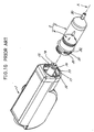
- the holding pieces 14, 14 at the front end of the piston force the pair of legs 71, 71, projecting from the rear side of the plunger 4, away from each other and are brought into engagement with the claws 76, 76 at the front side thereof (see FIG. 13). Since the front end face of the piston 13 comes into pushing contact with the plunger body 3, the plunger 4 advances, whereby the liquid agent in the syringe 2 is injected into the vascular system of the human body or animal as described above.
- the syringe body 3 is rotated through about 90 deg in a direction opposite to the direction in which the body is rotated for connection. This releases the ridge 31 of the syringe body 3 from engagement with the syringe holding flange 12 of the injector socket 11 and the claws 76, 76 of the plunger 4 from engagement with the holding pieces 14, 14 of the piston 13. The syringe 2 is removed from the socket 11.
- the syringe 2 shown in FIG. 11 and described above needs to be so designed as to withstand the pressure of injecting the liquid agent. As shown in FIG. 12, such a syringe 2 is also used as sheathed in a reinforcing case 200 on a turret 100 for connection to an injector 1.
- this type of syringe 2 comprises a syringe body 3 and a plunger 4, whereas the syringe body 3 need not withstand the internal pressure involved in injecting the liquid agent but has characteristics to slightly expand under the internal pressure.
- the syringe body 3 is provided at its rear end with parallel flanges 36, 36 each having a cut portion 37 for preventing rotation.
- the syringe 2 is removably fitted into the case or pressure jacket 200 supported by the turret 100 and is set in position.
- the turret 100 has stepped through bores 101, 101 at opposite sides of a hole 102 which provides the center of rotation of the turret 100.
- Tubular transparent reinforcing cases or pressure jackets 200, 200 are inserted from behind the turret 100 through the respective bores 101, 101 in the turret 100.
- the reinforcing case 200 has a rear end provided with a flange 201 serving as a retainer and a front end tapered in the form of a cone and formed with a hole 202 for a nozzle 30 of the syringe body 3 to extend therethrough.
- the injector 1 is provided with a turret rotating support pin 16 above a piston 13 and a turret receiving portion 18 below the piston 13.
- the syringe 2 is inserted into one of the reinforcing cases 200 on the turret 100, the support pin 16 is fitted into the hole 102 in the turret 100, the forward end of a screw 104 driven into the turret 100 orthogonally to the hole 102 is fitted into a groove 17 in the support pin 16, and one end of the turret 100 is engaged with the receiving portion 18 projecting from the injector 1 to prevent the turret 100 from slipping off.
- the syringe body 3 is expanded into intimate contact with the inner surface of the reinforcing case 200 by the internal pressure acting on the syringe body 3 when the liquid agent in the syringe 2 is injected by the advancement of the piston 13.
- the syringe body 3 withstands the internal pressure of injection by virtue of the strength of the case or pressure jacket 200.
- the elastic material in this region is compressed to a higher degree, making it possible to inject the liquid agent within the syringe body 3 into the vascular system of the human body or animal at a higher pressure than conventionally. Accordingly, the liquid agent can be injected into arterial vessels at a pressure higher than arterial blood pressure.
- the elastic cover 9 is stretched further rearward by the advance of the piston 13, but blocked by the backplate 62 and forced into a minute clearance between the periphery of the backplate 62 and the inner surface of the syringe body 3.
- This entails the problem that the portion of the cover 9 forced in has its surface scraped off in a very small amount by pressing contact with the syringe body 3, leaving scraped-off minute fragments on the syringe body inner surface during continued injection.
- the elastic cover 9 thus forced in offers excessive resistance to the advancement of the plunger 4.
- the present invention provides a syringe which is usable for high-pressure injection without permitting an elastic plunger cover to release scraped-off minute fragments thereof into the syringe while allowing the plunger to advance therein.
- the present invention provides a medical syringe 2 comprising a cylindrical syringe body 3 and a plunger 4 fitted in the syringe body 3 for injecting a liquid agent filled in the syringe body 3 from the syringe body 3 into the vascular system of a human body or animal by advancing the plunger 4 relative to the syringe body 3, the plunger 4 comprising a plunger body 5 and an elastic cover 9 fitted over the plunger body 5 from the front, the plunger body 5 being provided with a backplate 62 at a rear end thereof, the backplate 62 having an annular groove 68 forwardly opened and formed in a front surface thereof in the vicinity of an outer periphery thereof.
- the elastic cover 9 over the plunger body 5 stretches rearward in sliding contact therewith and is forced in between the plunger body 5 and the inner surface of the syringe body 3 and thereby compressed to a higher degree to produce an enhanced sealing effect.
- the rear end of the elastic cover 9 is stretched rearward by the advance of the plunger 4, the stretched portion is allowed to escape into the annular groove 68 forwardly opened and formed in the front surface outer peripheral portion of the backplate 62.
- An outer annular wall 68c defining the annular groove 68 serves to guide the outer periphery of the rearwardly stretched portion of the elastic cover 9 toward the annular groove 68.
- the base end of the elastic cover 9 escaping into the annular groove 68 fills up the groove 68, pressing the inner surface of the syringe body 3 to achieve a further improved sealing effect.
- the liquid agent within the syringe body 3 can be injected into the vascular system of the human body or animal with an exceedingly higher pressure than is the case with the syringe 2 disclosed in International Publication No. WO 98/20920 described, by virtue of the function of the annular groove 68 of the plunger 4.
- a high pressure is available in the range of 87 kg/cm 2 to 98 kg/cm 2 without entailing problems such as the release of scraped-off fragments of the elastic cover 9 of the plunger 4 and the failure of the plunger 4 to advance.
- the ridge 95 can easily escape into the annular groove 68 when the rear end of the elastic cover 9 is stretched rearward by the advance of the plunger 4.
- the elastic cover 9 can be prevented from slipping off the plunger body 5 by fitting an inward flange 94 formed on the inner surface of the elastic cover 9 into the recessed portion 52, before the plunger body 5 is fitted into the syringe body 3 in the assembling step.
- the backplate 62 can be given an increased strength without giving an increased thickness to the groove-defining walls of the backplate.
- annular groove 68 is shaped in conformity with the shape of the annular ridge 95 at the rear end of the elastic cover 9 in cross section, the inclination of the groove-defining side faces 68a, 68b enables the annular ridge 95 to ingress into the groove 68 for escape with greater ease.
- the elastic cover 9 It is desired to mold the elastic cover 9 from a composition which has incorporated therein a material, such as paraffin wax or polyethylene, having solid lubricity, or a composition which has incorporated therein a superfine speherical lubricating component of polyethylene, nylon, Teflon or like synthetic resin.
- the elastic cover 9 is then slidable on the inner surface of the syringe body 3 with improved smoothness to reduce the resistance to the injection by the plunger.
- the syringe 2 of the invention is characterized by the plunger 4 to be fitted in the body 3 of the syringe.
- the means for connecting the syringe 2 to an injector 1 is not limited to the one shown in FIGS. 10 and 11 or to the one comprising the turret 100 shown in FIG. 12. Any connecting means is usable insofar as it is so constructed that the syringe body 3 can be supported directly or indirectly by the injector for a piston 13 to push the plunger 4.
- the plunger 4 comprises a plunger body 5 made.from a synthetic resin, and an elastic cover 9 fitted over the plunger body.
- the plunger body 5 has a conical portion 81 at its front end, a hollow truncated cone 82 integral with the conical portion 81, positioned at a rear portion thereof and formed with a surface tapered at a smaller angle than the conical portion 81, and a backplate 62 at its rear end.
- the backplate 62 has a diameter greater than the maximum diameter of the truncated cone 82.
- the plunger body 5 has a recessed portion 52 formed between the backplate 62 and the truncated cone 82 and extending over the entire circumference thereof.
- the plunger body 5 may be composed integrally of the conical portion 81, truncated cone 82 and backplate 62, whereas according to the illustrated embodiment, the backplate 62 is formed as a separate part and fitted in the truncated cone 82 to ensure a convenient molding operation as will be described later.
- the truncated cone 82 is internally provided with a pair of connecting legs 71, 71 extending rearward from the rear end face of the plunger body 5 and each having an inward claw 76 at its rear end.
- An annular groove 68 concentric with the truncated cone 82 is formed in an outer peripheral portion of the front surface of the backplate 62 for receiving the portion of the elastic cover 92 which stretches rearward when the plunger 4 advances.
- the diameter of inner periphery of the annular groove 68 is smaller than the maximum diameter of the truncated cone 82. Accordingly, if the plunger body 5 is be molded integrally and when the mold is to be opened along a plane containing the center axis of the body, the annular groove 68 corresponds to an undercut, with the result that the plunger body 5 is not moldable as a single part.
- the plunger body 5 comprises three components, i.e., a first component 6, second component 7 and third component 8, each of which is formed from synthetic resin by injection molding and which are fitted to one anther as arranged axially thereof.
- the first component 6 comprises a columnar portion 61 having a short axial length, and a backplate 62 formed at the base end of the columnar portion 61 concentrically therewith and having a diameter greater than the diameter of the portion 61 but slightly smaller than the inside diameter of the syringe body 3.
- the first component 6 is generally shown in FIGS. 4 to 7.
- the columnar portion 61 has a pair of projections 63, 63 projecting from its front end and positioned at opposite sides of the axis of the portion 61 on a diametrical line thereof.
- Spaces 60, 69 extending through the columnar portion 61 axially thereof are formed respectively between the projections 63, 63 and between each projection 63 and the peripheral wall of the portion 61.
- Each projection 63 has an engaging stepped portion 64 formed in its back, and a guide face 65 inwardly inclined and extending from the stepped portion 64 to its front end.
- the columnar portion 61 has a circumferential groove 66 formed in the outer periphery of a front portion thereof, and a tapered surface 67 extending from the groove 66 to the front edge of the portion 61 with a gradually decreasing diameter.
- the aforementioned annular groove 68 formed in the front surface of the backplate 62 integral with the columnar portion 61 is so shaped in cross section that opposite side faces 68a, 68b defining the groove 68 are inclined toward each other to give the groove a width decreasing toward its bottom.
- the inner peripheral side face 68a defining the groove 68 is inclined more gently than the outer peripheral side face 68b.
- the outer annular wall 68c thus inclined to define the annular groove 68 therefore has a wall thickness gradually decreasing toward the opening side of the groove 68.
- the annular groove 68 has such a volume that the portion of the elastic cover 9 which is stretched rearward by the advance of the plunger 4 ingresses into and fills the groove 68 as will be described later.
- the second component 7 has two legs 71, 71 which are arranged in parallel as spaced apart by a greater distance than the pair of projections 63, 63 of the first component 6.
- the front ends of the legs 71, 71 are interconnected by a bar 72. Projecting rearward from the bar 72 are a pair of connecting pieces 73, 73 in parallel to the legs 71.
- Each connecting piece 73 has at its rear end a hook 74 engageable with the stepped portion 64 of the projection 63 of the first component 6.
- the hook 74 is formed with a slope 75 inclined along the slope of the guide face 65 of the projection 63.
- the legs 71, 71 of the second component 7 are flexible to move away from each other.
- Each leg 71 is provided at the rear end thereof with a claw 76 engageable with a plunger holding piece 14 of piston 13 of the injector 1.
- the third component 8 comprises a conical portion 81 and a truncated cone 82 integral therewith and is in the form of a hollow body having a flaring rear portion with an opening.
- the conical portion 81 has an angle of about 45 deg with the axis thereof.
- the tapered surface of the truncated cone 82 has an angle in the range of 3 deg to 15 deg, preferably 4 deg to 10 deg, with the axis thereof.
- the third component 8 has at its opening side a circumferential ridge 83 formed on the inner surface thereof and fittable in the circumferential groove 66 in the front end of columnar portion 61 of the first component 6.
- the ridge 83 is not continuous in an annular form but is divided at a plurality of locations, i.e., at three portions according to the embodiment. At the divided portions, the third component 8 has a reduced wall thickness and is easily elastically deformable.
- the third component 8 has air vents 85 extending through the conical portion 81.
- the legs 71, 71 of the second component 7 are inserted through the respective outer spaces 69, 69 of the first component 6 from the front while inwardly deflecting the legs to bring the connecting pieces 73, 73 of the second component 7 into bearing contact with the respective projections 63, 63.
- the second component 7 is further pushed in, whereby the connecting pieces 73, 73 are deflected outward, with the projections 63, 63 deflected inward, permitting the connecting pieces 73, 73 to be pushed in.
- each connecting piece 73 moves over the guide face 65 of the projection 63 to the stepped portion 64 thereof, the connecting piece 73 and the projection 63 restore themselves elastically, causing the hook 74 to engage in the stepped portion 64, whereby the first component 6 and the second component 7 are joined together.
- the third component 8 is fitted to the first component 6 from the front.
- the ridge 83 of the third component 8 comes into contact with the front-end tapered surface 67 of the columnar portion 61 of the first component 6.
- the third component 8 elastically deforms at the divided portions of the ridge 83, permitting the ridge 83 to fit into the circumferential groove 66 of the first component 6.
- the elastic cover 9 is in the form of a hollow body having a conical portion 91, cylindrical portion 92 continuous with the portion 91, and inward flange 94 projecting from the rear end of the cylindrical portion 92 so as to cover the conical portion 81, truncated cone 82 and recessed portion 52 of the plunger body 5.
- the cylindrical portion 92 has an inner peripheral surface which is inclined in conformity with the inclination of the truncated cone 82 of the third component 8.
- the cylindrical portion 92 has a wall thickness gradually decreasing toward the rear end thereof.
- the cylindrical portion 92 is provided on its outer periphery with a plurality of, preferably at least three, ribs 93 for affording an effective liquid-tight seal to hold a liquid agent filled in the syringe body 4.
- the straight distance L from the front edge of the foremost rib to the rear edge of the rearmost rib be at least 30% of the inside diameter D of the syringe body 3 (L>0.3D). This prevents the plunger 4 from inclining relative to the axis of the syringe body 3 during the movement of the plunger 4, enabling the plunger 4 to move smoothly.
- annular ridge 95 movable into the annular groove 68 of the first component 6 is formed on the rear end face of the elastic cover 9.
- the annular ridge 95 has an inner peripheral face 95a and an outer peripheral face 95b which are inclined at equal angles so as to give the ridge 95 a width decreasing rearward.
- the inclination of the outer peripheral face 95b is smaller than that of the outer side face 68b defining the annular groove 68.
- annular ridge 95 is slightly smaller than the groove 68 in cross sectional area.
- the elastomer composition for forming the elastic cover 9 has incorporated therein a lubricating component having solid lubricity, such as paraffin wax or one of polyethylenes having varying degrees of polymerization, or a superfine spherical rigid lubricating component of polyethylene, nylon, Teflon or the like.
- a lubricating component having solid lubricity such as paraffin wax or one of polyethylenes having varying degrees of polymerization, or a superfine spherical rigid lubricating component of polyethylene, nylon, Teflon or the like.
- the elastic cover 9 may have a projection 96 formed on the front end of the conical portion 91 and similar to that of the conventional cover as indicated in the dashed line in FIG. 1.
- the projection 96 advances into a nozzle 30 at the front end of the syringe body, forcing out the entire quantity of the liquid agent within the syringe, thereby preventing waste.
- the syringe body 3 is prefilled with the liquid agent to be injected and sealed by the plunger (4) at a rear portion thereof, and has its front nozzle 30 temporarily sealed so as not to permit leakage of the liquid agent.
- the entire inner surface of the syringe body 3 is uniformly coated with a very small amount of liquid polydimethylsiloxane so as to render the plunger 4 smoothly slidable on the inner surface of the syringe 2.
- This liquid is usually known as a silicone oil, which is, for example, Silicone 360 Medical Fluid, product of Dow Corning Corporation.
- the syringe body 3 is fixed in the socket 11 of the injector I in the same manner as in the prior art (see FIG. 10) by rotating the syringe body 3 with its rear end fitted in the socket 11, and positioning the ridge 31 of the syringe body 3 on the rear side of the syringe holding flange 12.
- the plunger 4 advances, whereby the liquid agent filled in the syringe body 3 can be injected into the vascular system of the human body or animal from the nozzle 30 of the syringe body 3 through a tube (not shown).
- the elastic cover 9 stretches rearward while sliding over the plunger body 5, and is forced in between the plunger body 5 and the inner surface of the syringe body 3 and compressed to a higher degree to produce an enhanced sealing effect. As this phenomenon spreads, the rear end of the cover 9 stretches rearward, ingressing into the annular groove 68 of the backplate 62 for escape.
- the outer annular wall 68c defining the annular groove 68 has a wall thickness gradually decreasing toward the opening side of the groove 68, while the inside face 68b of the wall 68c is so inclined as to approach the axis of the plunger 4 as it extends toward the groove bottom. This enables the annular ridge 95 of the elastic cover 9 to smoothly ingress into the annular groove 68 to escape from confinement by being guided by the inclined inside face 68b of the annular wall 68c.
- the structure of the invention eliminates the conventional problem that in the course of advance of the plunger 4, the rearwardly stretching portion of the elastic cover 9, which portion is prevented from escaping, wedges into a very small clearance between the outer periphery of the backplate 62 and the inner surface of the syringe body 3 to produce scraped-off fragments or other problems.
- the elastic cover rear portion ingressing into the annular groove further fills up the annular groove 68 to press on the inner surface of the syringe body 3, producing a more improved sealing effect.
- the liquid agent within the syringe body 3 can be injected into the vascular system of the human body or animal with a higher pressure than is available with the syringe 2 of International Publication No. WO 98/20920 described above, by virtue of the annular groove 68 of the plunger 4.
- a high pressure ranging from 87 kg/cm 2 to 98 kg/cm 2 is applied for injection, the elastic cover 9 of the plunger 4 releases no scraped-off fragments, or troubles such as failure of the plunger 4 to advance will not develop, thereby providing a plunger having high reliability.
- FIG. 12 it is preferable to use the arrangement of FIG. 12 for accommodating the syringe 2 in the reinforcing case or pressure jacket 200 for injecting the liquid agent. Alternately, however, a pressure jacket-less syringe (as shown in FIG. 10) can be used
- the plunger body 5 has the recessed portion 52 formed in its periphery between the truncated cone 82 and the backplate 62 and extending over the entire circumference thereof, and the inward flange 94 formed along the opening edge of the elastic cover 9 is fitted in the recessed portion 52. This holds the plunger body 5 and the elastic cover 9 assembled, obviating the likelihood that the elastic cover 9 will slip off the plunger body 5 before the plunger 4 is fitted into the syringe body 3.
- the elastic cover 9 is fitted over the plunger body 5 with a small clearance 90 formed between the cover 9 and the front end of the conical portion 81. This renders the cover 9 rearwardly stretchable with greater ease when the plunger 4 advances, permitting the cover 9 to be compressed to a higher degree at the head portion and inside the syringe body 3.
- liquid polydimethylsiloxane may be applied to the inner surface of the syringe body 3, wherein the liquid agent filled in the syringe body 3 could be forced out through the seal portion under the above-mentioned high pressure of 87 kg/cm 2 to 98 kg/cm 2 acting on the contact surface of the plunger 4. Further, it is likely that the polydimethylsiloxane is not transported to the portion of inner wall surface to be contacted with the syringe body 3 anew during the movement of the plunger 4, thus failing to maintain suitable lubricity.
- the composition to be molded into the elastic cover 9 has incorporated therein a lubricating component, such as paraffin wax or polyethylene, having solid lubricity, or a superfine spherical lubricating component such as polyethylene, nylon or Teflon.
- a lubricating component such as paraffin wax or polyethylene, having solid lubricity, or a superfine spherical lubricating component such as polyethylene, nylon or Teflon.
- a lubricating component such as paraffin wax or polyethylene, having solid lubricity
- a superfine spherical lubricating component such as polyethylene, nylon or Teflon.
- blooming that is, the phenomenon of becoming distributed and separating out on the surface of the product during molding. This results in more effective lubricity than is otherwise attainable by the proportion of the lubricating component used, rendering the elastic cover 9 slidable more smoothly on the inner surface of the syringe body 3 and reducing the resistance to the injection
- the plunger body 5 has the rearwardly flaring truncated cone 82 so as to compress the elastic cover 9 to a higher degree between the cone 82 and the inner surface of the syringe body 3 by a wedging effect with the advance of the plunger 4.
- the plunger body 5 is not limited to this construction; the outer peripheral portion of the plunger body 5 corresponding to the portion of the elastic cover 9 which is in contact with the inner surface of the syringe body 3 can be in the form of a cylindrical surface parallel to the inner surface of the syringe body 3.
- the plunger body 5 thus constructed is of course also effective for preventing the rear end of the elastic cover 9 from biting into the minute clearance between the outer periphery of the backplate 62 and the inner surface of the syringe body 3 and releasing scraped-off fragments.
- the front portion of the plunger body 5 is not limited to the conical portion 81 of the embodiment, but can be, for example, approximately hemispherical insofar as the front portion has a diameter gradually decreasing toward the front end.
- the side faces 68a, 68b defining the annular groove 68 in the front surface of the backplate 62 of the plunger body 5 need not always be inclined but can be so curved as to give the groove 68 a width decreasing toward the groove bottom.
- the backplate 62 can be increased in strength also in this case without giving an increased thickness to the groove-defining walls thereof.
- the present invention is applicable similarly to syringes 2 of the type to be provided in an empty state filled with no liquid agent.
- the syringe is filled with a liquid agent by moving the plunger 4 rearwardly of the syringe body 3 to draw the agent into the syringe body 3.
- the syringe 2 of the present invention can be used also as connected to a mechanism which retracts the syringe body 3, with the plunger 4 held in a fixed position, to advance the plunger 4 relative to the syringe body 3.
Abstract
Description
- The present invention relates to syringes fillable with a liquid agent for use as attached to injectors for medical procedures, such as angiography, computerized tomography, NMR/MRI, etc., to be performed with a contrast medium, chemical agent or like liquid agent injected into the vascular system of the human body or an animal.
- As disclosed in U.S. Patent No. 4,006,736, syringes for use in examining patients in medical procedures are used by attaching the main body of the syringe to an injector and fixing a plunger fitted in the syringe body in intimate contact therewith to a piston of the injector. The piston advances at a speed controlled by a control circuit of the injector, pushing the plunger to inject a liquid agent filled in the syringe into the vascular system of the patient.
- Further, U.S. Patent No. 4,677,980 discloses a syringe including a plunger which is connectable to a piston or disconnectable therefrom by rotating the entire syringe through about 90 deg relative to the piston, with the plunger held in contact with the forward end of the piston.
- Further International Publication No. WO 98/20920 (corresponding to Japanese Patent Application No. 522638/1998) discloses a
syringe 2 shown in FIGS. 10 and 11. - The
syringe 2 comprises acylindrical syringe body 3 and a plunger 4 fitted in the syringe body. Thesyringe 2 is connected to an injector 1 by removably fixing a base end of thesyringe body 3 in a syringe socket 11 of the injector 1 and releasably engaging the plunger 4 of thesyringe 2 with apiston 13 which is movable out of or into the socket 11 centrally shown) incorporated in the injector 1, thereby advancing the plunger 4 toward the forward end of thesyringe body 3 to inject a liquid agent filled in thesyringe body 3 into the vascular system of the human body or an animal through a tube (not shown) from anozzle 30 at the front end of thesyringe body 3. - In the following description, the term "front" or "forward" refers to one side of the
syringe 2 where thesyringe body 3 is connected to the patient and the liquid agent is forced out by the plunger 4, and the term "rear" or "rearward" refers to the other side opposite to the above side where the syringe is connected to the injector. - The inner periphery of the socket 11 of the injector 1 is provided with
syringe holding flanges syringe body 3 radially thereof areridges 31 engageable with theflanges flange 32 adapted for bearing contact with the end face of the socket 11. - The
piston 13 is provided at its front end withplunger holding pieces piston 13. - With reference to FIG. 13, the plunger 4 disclosed in the foregoing publication WO No. 98/20920 comprises a plunger body 5 and an elastic cover 9 fitted over the body 5.
- The plunger body 5 comprises two members which are fitted together, i.e., a
conical portion 81 at the front end, and a hollow truncatedcone 82 fitted to theconical portion 81, extending rearward and having a gently tapered conical surface. - A
circular backplate 62 extends from the rear end of thetruncated cone 82 radially thereof, with arecessed portion 52 formed between thebackplate 62 and thecone 82 over the entire circumference thereof. - Projecting rearward from the rear end of the
conical portion 81 are a pair of connectinglegs inward claw 76. - The elastic cover 9 is fitted over the plunger body 5 to extend over the
conical portion 81 thereof to therecessed portion 52, and comprises a hollowconical portion 91, acylindrical portion 92 extending from theconical portion 91, aninward flange 94 projecting from the rear end of thecylindrical portion 92 and aprojection 96 extending forward from the front end of theconical portion 91. A plurality ofribs cylindrical portion 92 over the entire circumference thereof. - The
projection 96 is positioned in thetubular nozzle 30 at the front end of thesyringe body 3 on completion of advance of the plunger 4, minimizing the quantity of the liquid agent remaining within thesyringe body 3 and to be wasted. - The hollow
conical portion 91 of the elastic cover 9 covers theconical portion 81 of the plunger body 5 with asmall space 90 left therebetween. Thecylindrical portion 92 covers thetruncated cone 82 in intimate contact therewith, with theinward flange 94 fitting in therecessed portion 52 around thecone 82. - The
syringe body 3 is fitted at its base end into the socket 11 of the injector 1 and then rotated through about 90 deg to position theridge 31 of thesyringe body 3 inside thesyringe holding flange 12 formed on the inner surface of the socket 11, whereby thesyringe body 3 is prevented from slipping out of the socket 11. - The
piston 13 of the injector 1 as retracted is positioned away from the plunger 4 of thesyringe 2. When thepiston 13 is projected outward gradually, however, theholding pieces legs claws piston 13 comes into pushing contact with theplunger body 3, the plunger 4 advances, whereby the liquid agent in thesyringe 2 is injected into the vascular system of the human body or animal as described above. - To remove the
syringe 2 from the injector 1 after it is used for injecting the liquid agent, thesyringe body 3 is rotated through about 90 deg in a direction opposite to the direction in which the body is rotated for connection. This releases theridge 31 of thesyringe body 3 from engagement with thesyringe holding flange 12 of the injector socket 11 and theclaws holding pieces piston 13. Thesyringe 2 is removed from the socket 11. - The
syringe 2 shown in FIG. 11 and described above needs to be so designed as to withstand the pressure of injecting the liquid agent. As shown in FIG. 12, such asyringe 2 is also used as sheathed in a reinforcingcase 200 on aturret 100 for connection to an injector 1. - Like the foregoing one, this type of
syringe 2 comprises asyringe body 3 and a plunger 4, whereas thesyringe body 3 need not withstand the internal pressure involved in injecting the liquid agent but has characteristics to slightly expand under the internal pressure. Thesyringe body 3 is provided at its rear end withparallel flanges cut portion 37 for preventing rotation. Thesyringe 2 is removably fitted into the case orpressure jacket 200 supported by theturret 100 and is set in position. - The
turret 100 has stepped throughbores hole 102 which provides the center of rotation of theturret 100. - Tubular transparent reinforcing cases or
pressure jackets turret 100 through therespective bores turret 100. - The reinforcing
case 200 has a rear end provided with aflange 201 serving as a retainer and a front end tapered in the form of a cone and formed with ahole 202 for anozzle 30 of thesyringe body 3 to extend therethrough. - The injector 1 is provided with a turret rotating
support pin 16 above apiston 13 and aturret receiving portion 18 below thepiston 13. - The
syringe 2 is inserted into one of the reinforcingcases 200 on theturret 100, thesupport pin 16 is fitted into thehole 102 in theturret 100, the forward end of ascrew 104 driven into theturret 100 orthogonally to thehole 102 is fitted into agroove 17 in thesupport pin 16, and one end of theturret 100 is engaged with thereceiving portion 18 projecting from the injector 1 to prevent theturret 100 from slipping off. - When the
piston 13 is connected to the plunger 4 of thesyringe 2 as inserted in thecase 200, with the axis of thecase 200 on theturret 100 aligned with the axis of thepiston 13, anothersyringe 2 can be inserted into or removed from theother case 200. - The
syringe body 3 is expanded into intimate contact with the inner surface of the reinforcingcase 200 by the internal pressure acting on thesyringe body 3 when the liquid agent in thesyringe 2 is injected by the advancement of thepiston 13. Thesyringe body 3 withstands the internal pressure of injection by virtue of the strength of the case orpressure jacket 200. - In the case of the
syringe 2 shown in FIGS. 11 and 12 and described above, thecylindrical portion 92 of the elastic cover 9 fitting around thetruncated cone 82 of the plunger body 5 is brought into intensely frictional contact with the inner surface of thesyringe body 3 when the plunger 4 advances as shown in FIG. 13, with the result that theconical portion 91 of the cover stretches toward a rearwardly tapered region between the inner surface of thesyringe body 3 and the truncatedportion 82 of the plunger body 5, producing an effect achieved as by forcing in a wedge (hereinafter referred to as a "wedging effect"). The elastic material in this region is compressed to a higher degree, making it possible to inject the liquid agent within thesyringe body 3 into the vascular system of the human body or animal at a higher pressure than conventionally. Accordingly, the liquid agent can be injected into arterial vessels at a pressure higher than arterial blood pressure. - However, higher pressures impose limitations on the operation of the
syringe 2 although it is adapted for high-pressure injection. - When the internal pressure of the
syringe 2 is increased by the advance of the plunger 4, an enhanced wedging effect presses the elastic cover 9 against the inner surface of thesyringe body 3 with a greater force, whereby thecylindrical portion 92 of the cover 9 is compressed under higher pressure and becomes seriously impaired in slipperiness. - The elastic cover 9 is stretched further rearward by the advance of the
piston 13, but blocked by thebackplate 62 and forced into a minute clearance between the periphery of thebackplate 62 and the inner surface of thesyringe body 3. This entails the problem that the portion of the cover 9 forced in has its surface scraped off in a very small amount by pressing contact with thesyringe body 3, leaving scraped-off minute fragments on the syringe body inner surface during continued injection. Furthermore, the elastic cover 9 thus forced in offers excessive resistance to the advancement of the plunger 4. - In view of the foregoing problems, the present invention provides a syringe which is usable for high-pressure injection without permitting an elastic plunger cover to release scraped-off minute fragments thereof into the syringe while allowing the plunger to advance therein.
- The present invention provides a
medical syringe 2 comprising acylindrical syringe body 3 and a plunger 4 fitted in thesyringe body 3 for injecting a liquid agent filled in thesyringe body 3 from thesyringe body 3 into the vascular system of a human body or animal by advancing the plunger 4 relative to thesyringe body 3, the plunger 4 comprising a plunger body 5 and an elastic cover 9 fitted over the plunger body 5 from the front, the plunger body 5 being provided with abackplate 62 at a rear end thereof, thebackplate 62 having anannular groove 68 forwardly opened and formed in a front surface thereof in the vicinity of an outer periphery thereof. - When the plunger 4 is pushed under high pressure against arterial blood pressure, the elastic cover 9 over the plunger body 5 stretches rearward in sliding contact therewith and is forced in between the plunger body 5 and the inner surface of the
syringe body 3 and thereby compressed to a higher degree to produce an enhanced sealing effect. Although the rear end of the elastic cover 9 is stretched rearward by the advance of the plunger 4, the stretched portion is allowed to escape into theannular groove 68 forwardly opened and formed in the front surface outer peripheral portion of thebackplate 62. - An outer annular wall 68c defining the
annular groove 68 serves to guide the outer periphery of the rearwardly stretched portion of the elastic cover 9 toward theannular groove 68. - This eliminates the conventional likelihood that the rearwardly stretched cover portion will wedge into the very small clearance between the outer periphery of the
backplate 62 and the inner surface of thesyringe body 3 during the advance of the plunger 4, producing minute scraped-off fragments and causing troubles such as the failure of the plunger 4 to advance. - The base end of the elastic cover 9 escaping into the
annular groove 68 fills up thegroove 68, pressing the inner surface of thesyringe body 3 to achieve a further improved sealing effect. - The liquid agent within the
syringe body 3 can be injected into the vascular system of the human body or animal with an exceedingly higher pressure than is the case with thesyringe 2 disclosed in International Publication No. WO 98/20920 described, by virtue of the function of theannular groove 68 of the plunger 4. A high pressure is available in the range of 87 kg/cm2 to 98 kg/cm2 without entailing problems such as the release of scraped-off fragments of the elastic cover 9 of the plunger 4 and the failure of the plunger 4 to advance. - When the rear end face of the elastic cover 9 is formed with an
annular ridge 95 concentric with the cover, theridge 95 can easily escape into theannular groove 68 when the rear end of the elastic cover 9 is stretched rearward by the advance of the plunger 4. - When the plunger body 5 has a
recessed portion 52 formed in the periphery of a rear portion thereof and continuous with the opening of the annular groove 58 of thebackplate 62, the elastic cover 9 can be prevented from slipping off the plunger body 5 by fitting aninward flange 94 formed on the inner surface of the elastic cover 9 into the recessedportion 52, before the plunger body 5 is fitted into thesyringe body 3 in the assembling step. - When the
annular groove 68 formed in the front surface of thebackplate 62 is so shaped in cross section that opposite side faces defining thegroove 68 are inclined or curved toward each other to give the groove a width decreasing toward its bottom, thebackplate 62 can be given an increased strength without giving an increased thickness to the groove-defining walls of the backplate. - Further when the
annular groove 68 is shaped in conformity with the shape of theannular ridge 95 at the rear end of the elastic cover 9 in cross section, the inclination of the groove-defining side faces 68a, 68b enables theannular ridge 95 to ingress into thegroove 68 for escape with greater ease. - It is desired to mold the elastic cover 9 from a composition which has incorporated therein a material, such as paraffin wax or polyethylene, having solid lubricity, or a composition which has incorporated therein a superfine speherical lubricating component of polyethylene, nylon, Teflon or like synthetic resin. The elastic cover 9 is then slidable on the inner surface of the
syringe body 3 with improved smoothness to reduce the resistance to the injection by the plunger. -
- FIG. 1 is an exploded perspective view of a plunger;
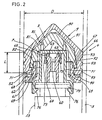
- FIG. 2 is a sectional view of the plunger;
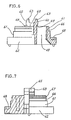
- FIG. 3 is a sectional view of the position relationship between an annular groove of the plunger and the rear end of an elastic cover in a load-free state;
- FIG. 4 is a plan view of a first component;
- FIG. 5 is a bottom view of the first component;
- FIG. 6 is a front view showing the first component partly in section taken along the line A-A in FIG. 4;
- FIG. 7 is a side elevation showing the first component partly in section taken along the line B-B in FIG. 4;
- FIG. 8 is a sectional view of a third component;
- FIG. 9 is a perspective view of the third component as it is seen from the bottom side;
- FIG. 10 is a perspective view showing an injector and a syringe of the prior art;
- FIG. 11 is a sectional view showing the syringe as connected to the injector according to the prior art;
- FIG. 12 is a perspective view showing a conventional syringe for use as sheathed in a reinforcing case and means for mounting the combination; and
- FIG. 13 is a sectional view of a conventional plunger.
-
- The
syringe 2 of the invention is characterized by the plunger 4 to be fitted in thebody 3 of the syringe. - The means for connecting the
syringe 2 to an injector 1 is not limited to the one shown in FIGS. 10 and 11 or to the one comprising theturret 100 shown in FIG. 12. Any connecting means is usable insofar as it is so constructed that thesyringe body 3 can be supported directly or indirectly by the injector for apiston 13 to push the plunger 4. - With reference to FIGS. 1 and 2, the plunger 4 comprises a plunger body 5 made.from a synthetic resin, and an elastic cover 9 fitted over the plunger body.
- The plunger body 5 has a
conical portion 81 at its front end, a hollowtruncated cone 82 integral with theconical portion 81, positioned at a rear portion thereof and formed with a surface tapered at a smaller angle than theconical portion 81, and abackplate 62 at its rear end. - The
backplate 62 has a diameter greater than the maximum diameter of thetruncated cone 82. - The plunger body 5 has a recessed
portion 52 formed between thebackplate 62 and thetruncated cone 82 and extending over the entire circumference thereof. - The plunger body 5 may be composed integrally of the
conical portion 81,truncated cone 82 andbackplate 62, whereas according to the illustrated embodiment, thebackplate 62 is formed as a separate part and fitted in thetruncated cone 82 to ensure a convenient molding operation as will be described later. - The
truncated cone 82 is internally provided with a pair of connectinglegs inward claw 76 at its rear end. - An
annular groove 68 concentric with thetruncated cone 82 is formed in an outer peripheral portion of the front surface of thebackplate 62 for receiving the portion of theelastic cover 92 which stretches rearward when the plunger 4 advances. - According to the embodiment, the diameter of inner periphery of the
annular groove 68 is smaller than the maximum diameter of thetruncated cone 82. Accordingly, if the plunger body 5 is be molded integrally and when the mold is to be opened along a plane containing the center axis of the body, theannular groove 68 corresponds to an undercut, with the result that the plunger body 5 is not moldable as a single part. - According to the embodiment, the plunger body 5 comprises three components, i.e., a
first component 6, second component 7 andthird component 8, each of which is formed from synthetic resin by injection molding and which are fitted to one anther as arranged axially thereof. - The
first component 6 comprises acolumnar portion 61 having a short axial length, and abackplate 62 formed at the base end of thecolumnar portion 61 concentrically therewith and having a diameter greater than the diameter of theportion 61 but slightly smaller than the inside diameter of thesyringe body 3. - The
first component 6 is generally shown in FIGS. 4 to 7. Thecolumnar portion 61 has a pair ofprojections portion 61 on a diametrical line thereof.Spaces columnar portion 61 axially thereof are formed respectively between theprojections projection 63 and the peripheral wall of theportion 61. - Each
projection 63 has an engaging steppedportion 64 formed in its back, and aguide face 65 inwardly inclined and extending from the steppedportion 64 to its front end. - The
columnar portion 61 has acircumferential groove 66 formed in the outer periphery of a front portion thereof, and atapered surface 67 extending from thegroove 66 to the front edge of theportion 61 with a gradually decreasing diameter. - With reference to FIG. 3, the aforementioned
annular groove 68 formed in the front surface of thebackplate 62 integral with thecolumnar portion 61 is so shaped in cross section that opposite side faces 68a, 68b defining thegroove 68 are inclined toward each other to give the groove a width decreasing toward its bottom. The inner peripheral side face 68a defining thegroove 68 is inclined more gently than the outer peripheral side face 68b. - The outer annular wall 68c thus inclined to define the
annular groove 68 therefore has a wall thickness gradually decreasing toward the opening side of thegroove 68. - The
annular groove 68 has such a volume that the portion of the elastic cover 9 which is stretched rearward by the advance of the plunger 4 ingresses into and fills thegroove 68 as will be described later. - With reference to FIGS. 1 and 2, the second component 7 has two
legs projections first component 6. The front ends of thelegs bar 72. Projecting rearward from thebar 72 are a pair of connectingpieces legs 71. - Each connecting
piece 73 has at its rear end ahook 74 engageable with the steppedportion 64 of theprojection 63 of thefirst component 6. Thehook 74 is formed with aslope 75 inclined along the slope of theguide face 65 of theprojection 63. - The
legs leg 71 is provided at the rear end thereof with aclaw 76 engageable with aplunger holding piece 14 ofpiston 13 of the injector 1. - With reference to FIGS. 8 and 9, the
third component 8 comprises aconical portion 81 and atruncated cone 82 integral therewith and is in the form of a hollow body having a flaring rear portion with an opening. - The
conical portion 81 has an angle of about 45 deg with the axis thereof. The tapered surface of thetruncated cone 82 has an angle in the range of 3 deg to 15 deg, preferably 4 deg to 10 deg, with the axis thereof. - The
third component 8 has at its opening side acircumferential ridge 83 formed on the inner surface thereof and fittable in thecircumferential groove 66 in the front end ofcolumnar portion 61 of thefirst component 6. - The
ridge 83 is not continuous in an annular form but is divided at a plurality of locations, i.e., at three portions according to the embodiment. At the divided portions, thethird component 8 has a reduced wall thickness and is easily elastically deformable. - The
third component 8 hasair vents 85 extending through theconical portion 81. - To assemble the plunger body 5 as shown in FIG. 2, the
legs outer spaces first component 6 from the front while inwardly deflecting the legs to bring the connectingpieces respective projections pieces projections pieces hook 74 of each connectingpiece 73 moving over theguide face 65 of theprojection 63 to the steppedportion 64 thereof, the connectingpiece 73 and theprojection 63 restore themselves elastically, causing thehook 74 to engage in the steppedportion 64, whereby thefirst component 6 and the second component 7 are joined together. - The
third component 8 is fitted to thefirst component 6 from the front. - The
ridge 83 of thethird component 8 comes into contact with the front-end taperedsurface 67 of thecolumnar portion 61 of thefirst component 6. When further pressed on, thethird component 8 elastically deforms at the divided portions of theridge 83, permitting theridge 83 to fit into thecircumferential groove 66 of thefirst component 6. With thethird component 8 joined to thefirst component 6, the plunger body 5 is completely assembled. - The elastic cover 9 is in the form of a hollow body having a
conical portion 91,cylindrical portion 92 continuous with theportion 91, andinward flange 94 projecting from the rear end of thecylindrical portion 92 so as to cover theconical portion 81,truncated cone 82 and recessedportion 52 of the plunger body 5. - The
cylindrical portion 92 has an inner peripheral surface which is inclined in conformity with the inclination of thetruncated cone 82 of thethird component 8. Thecylindrical portion 92 has a wall thickness gradually decreasing toward the rear end thereof. - The
cylindrical portion 92 is provided on its outer periphery with a plurality of, preferably at least three,ribs 93 for affording an effective liquid-tight seal to hold a liquid agent filled in the syringe body 4. - It is desired that the straight distance L from the front edge of the foremost rib to the rear edge of the rearmost rib be at least 30% of the inside diameter D of the syringe body 3 (L>0.3D). This prevents the plunger 4 from inclining relative to the axis of the
syringe body 3 during the movement of the plunger 4, enabling the plunger 4 to move smoothly. - As shown in FIG. 3, an
annular ridge 95 movable into theannular groove 68 of thefirst component 6 is formed on the rear end face of the elastic cover 9. Theannular ridge 95 has an inner peripheral face 95a and an outer peripheral face 95b which are inclined at equal angles so as to give the ridge 95 a width decreasing rearward. The inclination of the outer peripheral face 95b is smaller than that of the outer side face 68b defining theannular groove 68. - Although similar to the trapezoidal cross sectional form of the
annular groove 68, theannular ridge 95 is slightly smaller than thegroove 68 in cross sectional area. - The elastomer composition for forming the elastic cover 9 has incorporated therein a lubricating component having solid lubricity, such as paraffin wax or one of polyethylenes having varying degrees of polymerization, or a superfine spherical rigid lubricating component of polyethylene, nylon, Teflon or the like.
- When required, the elastic cover 9 may have a
projection 96 formed on the front end of theconical portion 91 and similar to that of the conventional cover as indicated in the dashed line in FIG. 1. When thesyringe 2 is used, theprojection 96 advances into anozzle 30 at the front end of the syringe body, forcing out the entire quantity of the liquid agent within the syringe, thereby preventing waste. - With the elastic cover 9 fitted over the plunger body 5, a
small clearance 90 is formed between theconical portion 81 of the plunger body 5 and the cover 9 as seen in FIG. 2. In the case of the cover 9 shown in FIG. 3, the rear end face of theannular ridge 95 is positioned substantially flush with the plane of opening of theannular groove 68 in thebackplate 62. - The
syringe body 3 is prefilled with the liquid agent to be injected and sealed by the plunger (4) at a rear portion thereof, and has itsfront nozzle 30 temporarily sealed so as not to permit leakage of the liquid agent. Before thesyringe body 3 is filled with the liquid agent, the entire inner surface of thesyringe body 3 is uniformly coated with a very small amount of liquid polydimethylsiloxane so as to render the plunger 4 smoothly slidable on the inner surface of thesyringe 2. This liquid is usually known as a silicone oil, which is, for example, Silicone 360 Medical Fluid, product of Dow Corning Corporation. - The
syringe body 3 is fixed in the socket 11 of the injector I in the same manner as in the prior art (see FIG. 10) by rotating thesyringe body 3 with its rear end fitted in the socket 11, and positioning theridge 31 of thesyringe body 3 on the rear side of thesyringe holding flange 12. - When the
piston 13 is gradually projected, thehook 74 of each connectingpiece 73 of the plunger 4 is engaged with the back side of theplunger holding piece 14 of thepiston 13. - When the
piston 13 is further projected, the plunger 4 advances, whereby the liquid agent filled in thesyringe body 3 can be injected into the vascular system of the human body or animal from thenozzle 30 of thesyringe body 3 through a tube (not shown). - When the plunger 4 is pushed forward under an extremely high pressure, the elastic cover 9 stretches rearward while sliding over the plunger body 5, and is forced in between the plunger body 5 and the inner surface of the
syringe body 3 and compressed to a higher degree to produce an enhanced sealing effect. As this phenomenon spreads, the rear end of the cover 9 stretches rearward, ingressing into theannular groove 68 of thebackplate 62 for escape. - The outer annular wall 68c defining the
annular groove 68 has a wall thickness gradually decreasing toward the opening side of thegroove 68, while the inside face 68b of the wall 68c is so inclined as to approach the axis of the plunger 4 as it extends toward the groove bottom. This enables theannular ridge 95 of the elastic cover 9 to smoothly ingress into theannular groove 68 to escape from confinement by being guided by the inclined inside face 68b of the annular wall 68c. - Accordingly, the structure of the invention eliminates the conventional problem that in the course of advance of the plunger 4, the rearwardly stretching portion of the elastic cover 9, which portion is prevented from escaping, wedges into a very small clearance between the outer periphery of the
backplate 62 and the inner surface of thesyringe body 3 to produce scraped-off fragments or other problems. - The elastic cover rear portion ingressing into the annular groove further fills up the
annular groove 68 to press on the inner surface of thesyringe body 3, producing a more improved sealing effect. - The liquid agent within the
syringe body 3 can be injected into the vascular system of the human body or animal with a higher pressure than is available with thesyringe 2 of International Publication No. WO 98/20920 described above, by virtue of theannular groove 68 of the plunger 4. Although a high pressure ranging from 87 kg/cm2 to 98 kg/cm2 is applied for injection, the elastic cover 9 of the plunger 4 releases no scraped-off fragments, or troubles such as failure of the plunger 4 to advance will not develop, thereby providing a plunger having high reliability. - It is preferable to use the arrangement of FIG. 12 for accommodating the
syringe 2 in the reinforcing case orpressure jacket 200 for injecting the liquid agent. Alternately, however, a pressure jacket-less syringe (as shown in FIG. 10) can be used - According to the embodiment, the plunger body 5 has the recessed
portion 52 formed in its periphery between thetruncated cone 82 and thebackplate 62 and extending over the entire circumference thereof, and theinward flange 94 formed along the opening edge of the elastic cover 9 is fitted in the recessedportion 52. This holds the plunger body 5 and the elastic cover 9 assembled, obviating the likelihood that the elastic cover 9 will slip off the plunger body 5 before the plunger 4 is fitted into thesyringe body 3. - With the embodiment, the elastic cover 9 is fitted over the plunger body 5 with a
small clearance 90 formed between the cover 9 and the front end of theconical portion 81. This renders the cover 9 rearwardly stretchable with greater ease when the plunger 4 advances, permitting the cover 9 to be compressed to a higher degree at the head portion and inside thesyringe body 3. - With the
common syringe 2, liquid polydimethylsiloxane may be applied to the inner surface of thesyringe body 3, wherein the liquid agent filled in thesyringe body 3 could be forced out through the seal portion under the above-mentioned high pressure of 87 kg/cm2 to 98 kg/cm2 acting on the contact surface of the plunger 4. Further, it is likely that the polydimethylsiloxane is not transported to the portion of inner wall surface to be contacted with thesyringe body 3 anew during the movement of the plunger 4, thus failing to maintain suitable lubricity. - According to the embodiment, the composition to be molded into the elastic cover 9 has incorporated therein a lubricating component, such as paraffin wax or polyethylene, having solid lubricity, or a superfine spherical lubricating component such as polyethylene, nylon or Teflon. Such a component often exhibits a phenomenon known as blooming, that is, the phenomenon of becoming distributed and separating out on the surface of the product during molding. This results in more effective lubricity than is otherwise attainable by the proportion of the lubricating component used, rendering the elastic cover 9 slidable more smoothly on the inner surface of the
syringe body 3 and reducing the resistance to the injection by the plunger 4. - According to the embodiment, the plunger body 5 has the rearwardly flaring truncated
cone 82 so as to compress the elastic cover 9 to a higher degree between thecone 82 and the inner surface of thesyringe body 3 by a wedging effect with the advance of the plunger 4. However, the plunger body 5 is not limited to this construction; the outer peripheral portion of the plunger body 5 corresponding to the portion of the elastic cover 9 which is in contact with the inner surface of thesyringe body 3 can be in the form of a cylindrical surface parallel to the inner surface of thesyringe body 3. The plunger body 5 thus constructed is of course also effective for preventing the rear end of the elastic cover 9 from biting into the minute clearance between the outer periphery of thebackplate 62 and the inner surface of thesyringe body 3 and releasing scraped-off fragments. - In practicing the present invention, the front portion of the plunger body 5 is not limited to the
conical portion 81 of the embodiment, but can be, for example, approximately hemispherical insofar as the front portion has a diameter gradually decreasing toward the front end. - Further in practicing the present invention, the side faces 68a, 68b defining the
annular groove 68 in the front surface of thebackplate 62 of the plunger body 5 need not always be inclined but can be so curved as to give the groove 68 a width decreasing toward the groove bottom. Thebackplate 62 can be increased in strength also in this case without giving an increased thickness to the groove-defining walls thereof. - The present invention is applicable similarly to
syringes 2 of the type to be provided in an empty state filled with no liquid agent. When to be used, the syringe is filled with a liquid agent by moving the plunger 4 rearwardly of thesyringe body 3 to draw the agent into thesyringe body 3. - The
syringe 2 of the present invention can be used also as connected to a mechanism which retracts thesyringe body 3, with the plunger 4 held in a fixed position, to advance the plunger 4 relative to thesyringe body 3.
Claims (5)
- A syringe comprising:a cylindrical syringe body (3); anda plunger (4) movably disposed within the syringe body (3) for injecting a liquid agent filled in the syringe body (3) from the syringe body (3) into the vascular system of a human body or animal, the plunger (4) comprising a plunger body (5) and an elastic cover (9) fitted over the plunger body from the front, the plunger body (5) comprising a backplate (62) at a rear end thereof, the backplate (62) defining an annular groove (68) forwardly opened and formed in a front surface thereof in the vicinity of an outer periphery thereof, the elastic cover (9) comprising a portion to be rearwardly stretched by friction with the syringe body (3) during advancement of the plunger (4) and operable to ingress into the annular groove (68).
- A syringe according to claim 1 wherein the elastic cover (9) further comprises an annular ridge (95) formed on a rear end face thereof and concentric with the elastic cover.
- A syringe according to claim 1 wherein the backplate (62) further comprises opposite side faces (68a), (68b) defining the annular groove (68) and inclined or curved to give the groove a width decreasing toward a bottom thereof.
- A syringe according to claim 1 wherein the elastic cover (9) is molded from a composition having incorporated therein paraffin wax, polyolefin or like material having solid lubricity.
- A syringe according to claim 1 wherein the syringe body (3) is prefilled with the liquid agent to be injected, sealed by the plunger (4) at a rear portion thereof and provided at a front portion thereof with a nozzle (30) temporarily sealed so as not to permit leakage of the liquid agent.
Applications Claiming Priority (2)
| Application Number | Priority Date | Filing Date | Title |
|---|---|---|---|
| US09/598,628 US6432089B1 (en) | 2000-06-21 | 2000-06-21 | Medical syringe |
| US598628 | 2000-06-21 |
Publications (2)
| Publication Number | Publication Date |
|---|---|
| EP1166807A1 true EP1166807A1 (en) | 2002-01-02 |
| EP1166807B1 EP1166807B1 (en) | 2005-11-23 |
Family
ID=24396323
Family Applications (1)
| Application Number | Title | Priority Date | Filing Date |
|---|---|---|---|
| EP01112046A Expired - Lifetime EP1166807B1 (en) | 2000-06-21 | 2001-05-23 | Medical syringe |
Country Status (7)
| Country | Link |
|---|---|
| US (1) | US6432089B1 (en) |
| EP (1) | EP1166807B1 (en) |
| JP (1) | JP4237929B2 (en) |
| AT (1) | ATE310548T1 (en) |
| DE (1) | DE60115151T2 (en) |
| DK (1) | DK1166807T3 (en) |
| ES (1) | ES2253300T3 (en) |
Cited By (14)
| Publication number | Priority date | Publication date | Assignee | Title |
|---|---|---|---|---|
| WO2005053771A2 (en) | 2003-11-25 | 2005-06-16 | Medrad, Inc. | Syringes, syringe interfaces and syringe plungers for use with medical injectors |
| WO2005079886A2 (en) * | 2004-02-13 | 2005-09-01 | Mallinckrodt Inc. | Keep vein open method and injector with keep vein open function |
| EP2554204A1 (en) * | 2010-03-29 | 2013-02-06 | Terumo Kabushiki Kaisha | Prefilled syringe |
| WO2014052306A1 (en) | 2012-09-28 | 2014-04-03 | Medrad, Inc. | Quick release plunger |
| EP2808046A3 (en) * | 2007-09-21 | 2015-11-25 | Imaxeon Pty Ltd | A releasable connecting mechanism |
| US9480797B1 (en) | 2015-10-28 | 2016-11-01 | Bayer Healthcare Llc | System and method for syringe plunger engagement with an injector |
| US9855390B2 (en) | 2006-03-15 | 2018-01-02 | Bayer Healthcare Llc | Plunger covers and plungers for use in syringes |
| WO2018129116A1 (en) * | 2017-01-06 | 2018-07-12 | Bayer Healthcare Llc | Syringe plunger with dynamic seal |
| USD847985S1 (en) | 2007-03-14 | 2019-05-07 | Bayer Healthcare Llc | Syringe plunger cover |
| US10806852B2 (en) | 2014-03-19 | 2020-10-20 | Bayer Healthcare Llc | System for syringe engagement to an injector |
| EP3760258A4 (en) * | 2018-03-28 | 2021-04-28 | TERUMO Kabushiki Kaisha | Liquid medicine ejection tool or gasket pressing tool for syringe, and liquid medicine administration tool provided therewith |
| USD942005S1 (en) | 2007-03-14 | 2022-01-25 | Bayer Healthcare Llc | Orange syringe plunger cover |
| USD1002840S1 (en) | 2007-03-14 | 2023-10-24 | Bayer Healthcare Llc | Syringe plunger |
| US11883636B2 (en) | 2018-02-27 | 2024-01-30 | Bayer Healthcare Llc | Syringe plunger engagement mechanism |
Families Citing this family (54)
| Publication number | Priority date | Publication date | Assignee | Title |
|---|---|---|---|---|
| US20110282185A1 (en) * | 1998-06-29 | 2011-11-17 | Bracco Suisse S.A. | Gasket for Pre-Filled Syringe and Pre-Filled Syringe |
| US6800071B1 (en) * | 1998-10-29 | 2004-10-05 | Medtronic Minimed, Inc. | Fluid reservoir piston |
| US6817990B2 (en) * | 1998-10-29 | 2004-11-16 | Medtronic Minimed, Inc. | Fluid reservoir piston |
| US7063684B2 (en) * | 1999-10-28 | 2006-06-20 | Medtronic Minimed, Inc. | Drive system seal |
| US6652489B2 (en) * | 2000-02-07 | 2003-11-25 | Medrad, Inc. | Front-loading medical injector and syringes, syringe interfaces, syringe adapters and syringe plungers for use therewith |
| AUPQ867900A0 (en) | 2000-07-10 | 2000-08-03 | Medrad, Inc. | Medical injector system |
| US8909325B2 (en) | 2000-08-21 | 2014-12-09 | Biosensors International Group, Ltd. | Radioactive emission detector equipped with a position tracking system and utilization thereof with medical systems and in medical procedures |
| US8565860B2 (en) | 2000-08-21 | 2013-10-22 | Biosensors International Group, Ltd. | Radioactive emission detector equipped with a position tracking system |
| US8489176B1 (en) | 2000-08-21 | 2013-07-16 | Spectrum Dynamics Llc | Radioactive emission detector equipped with a position tracking system and utilization thereof with medical systems and in medical procedures |
| US8586932B2 (en) | 2004-11-09 | 2013-11-19 | Spectrum Dynamics Llc | System and method for radioactive emission measurement |
| US7968851B2 (en) | 2004-01-13 | 2011-06-28 | Spectrum Dynamics Llc | Dynamic spect camera |
| US9470801B2 (en) | 2004-01-13 | 2016-10-18 | Spectrum Dynamics Llc | Gating with anatomically varying durations |
| US9040016B2 (en) | 2004-01-13 | 2015-05-26 | Biosensors International Group, Ltd. | Diagnostic kit and methods for radioimaging myocardial perfusion |
| WO2007010534A2 (en) | 2005-07-19 | 2007-01-25 | Spectrum Dynamics Llc | Imaging protocols |
| US7176466B2 (en) | 2004-01-13 | 2007-02-13 | Spectrum Dynamics Llc | Multi-dimensional image reconstruction |
| US8571881B2 (en) | 2004-11-09 | 2013-10-29 | Spectrum Dynamics, Llc | Radiopharmaceutical dispensing, administration, and imaging |
| EP1778957A4 (en) | 2004-06-01 | 2015-12-23 | Biosensors Int Group Ltd | Radioactive-emission-measurement optimization to specific body structures |
| US8000773B2 (en) | 2004-11-09 | 2011-08-16 | Spectrum Dynamics Llc | Radioimaging |
| EP1827505A4 (en) | 2004-11-09 | 2017-07-12 | Biosensors International Group, Ltd. | Radioimaging |
| US8615405B2 (en) | 2004-11-09 | 2013-12-24 | Biosensors International Group, Ltd. | Imaging system customization using data from radiopharmaceutical-associated data carrier |
| US9943274B2 (en) | 2004-11-09 | 2018-04-17 | Spectrum Dynamics Medical Limited | Radioimaging using low dose isotope |
| US9316743B2 (en) | 2004-11-09 | 2016-04-19 | Biosensors International Group, Ltd. | System and method for radioactive emission measurement |
| WO2008059489A2 (en) | 2006-11-13 | 2008-05-22 | Spectrum Dynamics Llc | Radioimaging applications of and novel formulations of teboroxime |
| US20060106347A1 (en) * | 2004-11-17 | 2006-05-18 | Liebel-Flarsheim Company | Disposable front loadable syringe and injector |
| DE102004059126B4 (en) * | 2004-12-08 | 2014-01-16 | Roche Diagnostics Gmbh | Adapter for injection device |
| EP1849490A4 (en) * | 2005-02-15 | 2009-09-16 | Top Kk | Syringe |
| US8837793B2 (en) | 2005-07-19 | 2014-09-16 | Biosensors International Group, Ltd. | Reconstruction stabilizer and active vision |
| KR101316487B1 (en) * | 2005-08-01 | 2013-10-08 | 니프로 가부시키가이샤 | Plunger for injector, and syringe and prefilled syringe that use the same |
| WO2007118907A1 (en) * | 2006-04-19 | 2007-10-25 | Novo Nordisk A/S | A fluid infusion system, a method of assembling such system and drug reservoir for use in the system |
| US8894974B2 (en) | 2006-05-11 | 2014-11-25 | Spectrum Dynamics Llc | Radiopharmaceuticals for diagnosis and therapy |
| US8038656B2 (en) * | 2006-09-29 | 2011-10-18 | Tyco Healthcare Group Lp | Detachable plunger rod syringe |
| US9275451B2 (en) | 2006-12-20 | 2016-03-01 | Biosensors International Group, Ltd. | Method, a system, and an apparatus for using and processing multidimensional data |
| EP2187996B1 (en) * | 2007-08-13 | 2011-10-12 | Mallinckrodt LLC | Drive ram for medical injectors |
| US8521253B2 (en) | 2007-10-29 | 2013-08-27 | Spectrum Dynamics Llc | Prostate imaging |
| US20110005958A1 (en) * | 2009-07-09 | 2011-01-13 | Onpharma, Inc. | METHODS AND SYSTEMS FOR ADJUSTING THE pH OF MEDICAL BUFFERING SOLUTIONS |
| US8162917B2 (en) * | 2008-05-21 | 2012-04-24 | Onpharma, Inc. | Methods and apparatus for buffering anesthetics |
| US8585963B2 (en) * | 2009-07-09 | 2013-11-19 | Onpharma, Inc. | Methods and devices for sterilizing and holding buffering solution cartridges |
| WO2011006122A1 (en) * | 2009-07-09 | 2011-01-13 | Onpharma, Inc. | Methods and devices for sterilizing and holding buffering solution cartridges |
| US8338788B2 (en) | 2009-07-29 | 2012-12-25 | Spectrum Dynamics Llc | Method and system of optimized volumetric imaging |
| CN103533977A (en) | 2011-03-28 | 2014-01-22 | 贝克顿·迪金森公司 | Plastic stopper |
| JP6379033B2 (en) * | 2012-04-06 | 2018-08-22 | 厚夫 森 | Automatic rapid infusion or blood transfusion device |
| GB2504289A (en) * | 2012-07-24 | 2014-01-29 | Rifat Jan | Paste dispenser and paste receiving pouches |
| US11129934B2 (en) | 2014-10-28 | 2021-09-28 | Bayer Healthcare Llc | Self-orienting pressure jacket and pressure jacket-to-injector interface |
| RU2709546C2 (en) | 2014-10-28 | 2019-12-18 | БАЙЕР ХелсКер ЛЛСи | Self-oriented high-pressure casing and mechanism for high pressure casing and injector connection |
| NO2689315T3 (en) | 2014-10-28 | 2018-04-14 | ||
| US9199033B1 (en) | 2014-10-28 | 2015-12-01 | Bayer Healthcare Llc | Self-orienting syringe and syringe interface |
| CN105031775B (en) * | 2015-06-20 | 2018-07-03 | 南京感控通化工产品经营部 | High-pressure syringe piston docking facilities and method |
| US10835674B2 (en) | 2015-11-13 | 2020-11-17 | Bayer Healthcare Llc | Nested syringe assembly |
| AU2016356717B2 (en) * | 2015-11-18 | 2022-09-29 | Sio2 Medical Products, Inc. | Pharmaceutical package for ophthalmic formulations |
| US10549044B2 (en) * | 2016-06-09 | 2020-02-04 | Becton, Dickinson And Company | Spacer assembly for drug delivery system |
| US11191893B2 (en) | 2018-01-31 | 2021-12-07 | Bayer Healthcare Llc | System and method for syringe engagement with injector |
| JP7094906B2 (en) * | 2019-02-15 | 2022-07-04 | 三菱重工業株式会社 | Fluid material discharge device |
| CN110755716B (en) * | 2019-10-31 | 2022-01-07 | 宜昌市中心人民医院(三峡大学第一临床医学院、三峡大学附属中心人民医院) | Convenient abluent cardiovascular treatment is with interveneeing injection ware |
| WO2024006909A1 (en) * | 2022-07-01 | 2024-01-04 | Merit Medical Systems, Inc. | Plunger tip cover with locking members, systems, and methods |
Citations (4)
| Publication number | Priority date | Publication date | Assignee | Title |
|---|---|---|---|---|
| US5353691A (en) * | 1993-04-14 | 1994-10-11 | Habley Medical Technology Corp. | Self-lubricating piston for pharmaceutical container |
| US5785682A (en) * | 1995-03-22 | 1998-07-28 | Abbott Laboratories | Pre-filled syringe drug delivery system |
| US5947929A (en) * | 1997-08-22 | 1999-09-07 | Coeur Laboratories, Inc. | Front-load angiographic injector system, angiographic syringe and plunger for angiographic syringe |
| EP1002551A2 (en) * | 1998-11-19 | 2000-05-24 | Bracco International B.V. | Easy-slip plunger/plunger rod assembly for a syringe or a cartridge |
Family Cites Families (9)
| Publication number | Priority date | Publication date | Assignee | Title |
|---|---|---|---|---|
| US4006736A (en) | 1974-11-27 | 1977-02-08 | Medrad, Inc. | Angiographic injector |
| DE3587540T3 (en) | 1984-06-06 | 1998-01-22 | Medrad Inc | Angiography syringe for use with an angiography injector. |
| US5007904A (en) * | 1989-01-19 | 1991-04-16 | Coeur Laboratories, Inc. | Plunger for power injector angiographic syringe, and syringe comprising same |
| US4911695A (en) * | 1989-04-03 | 1990-03-27 | Coeur Laboratories, Inc. | Plunger for power-driven angiographic syringe, and syringe and power injector system utilizing same |
| US5300031A (en) | 1991-06-07 | 1994-04-05 | Liebel-Flarsheim Company | Apparatus for injecting fluid into animals and disposable front loadable syringe therefor |
| US5383858B1 (en) | 1992-08-17 | 1996-10-29 | Medrad Inc | Front-loading medical injector and syringe for use therewith |
| US5314415A (en) * | 1993-07-21 | 1994-05-24 | Sterling Winthrop Inc. | Aspirating plunger for power injector cartridges |
| EP0951306B1 (en) | 1996-11-12 | 2005-07-20 | Medrad Inc. | Prefillable syringes and injectors for use therewith |
| US5902276A (en) | 1996-11-26 | 1999-05-11 | Liebel-Flarsheim Company | Two-shot molded plunger |
-
2000
- 2000-06-21 US US09/598,628 patent/US6432089B1/en not_active Expired - Lifetime
- 2000-10-19 JP JP2000318814A patent/JP4237929B2/en not_active Expired - Lifetime
-
2001
- 2001-05-23 EP EP01112046A patent/EP1166807B1/en not_active Expired - Lifetime
- 2001-05-23 ES ES01112046T patent/ES2253300T3/en not_active Expired - Lifetime
- 2001-05-23 DE DE60115151T patent/DE60115151T2/en not_active Expired - Lifetime
- 2001-05-23 AT AT01112046T patent/ATE310548T1/en active
- 2001-05-23 DK DK01112046T patent/DK1166807T3/en active
Patent Citations (4)
| Publication number | Priority date | Publication date | Assignee | Title |
|---|---|---|---|---|
| US5353691A (en) * | 1993-04-14 | 1994-10-11 | Habley Medical Technology Corp. | Self-lubricating piston for pharmaceutical container |
| US5785682A (en) * | 1995-03-22 | 1998-07-28 | Abbott Laboratories | Pre-filled syringe drug delivery system |
| US5947929A (en) * | 1997-08-22 | 1999-09-07 | Coeur Laboratories, Inc. | Front-load angiographic injector system, angiographic syringe and plunger for angiographic syringe |
| EP1002551A2 (en) * | 1998-11-19 | 2000-05-24 | Bracco International B.V. | Easy-slip plunger/plunger rod assembly for a syringe or a cartridge |
Cited By (45)
| Publication number | Priority date | Publication date | Assignee | Title |
|---|---|---|---|---|
| US11596735B2 (en) | 2003-11-25 | 2023-03-07 | Bayer Healthcare Llc | Medical injector system |
| EP1687049A2 (en) * | 2003-11-25 | 2006-08-09 | Medrad, Inc. | Syringes, syringe interfaces and syringe plungers for use with medical injectors |
| EP1687049A4 (en) * | 2003-11-25 | 2012-11-14 | Medrad Inc | Syringes, syringe interfaces and syringe plungers for use with medical injectors |
| US9694131B2 (en) | 2003-11-25 | 2017-07-04 | Bayer Healthcare Llc | Medical injector system |
| WO2005053771A2 (en) | 2003-11-25 | 2005-06-16 | Medrad, Inc. | Syringes, syringe interfaces and syringe plungers for use with medical injectors |
| US10894124B2 (en) | 2003-11-25 | 2021-01-19 | Bayer Healthcare Llc | Medical injector system |
| US10434249B2 (en) | 2003-11-25 | 2019-10-08 | Bayer Healthcare Llc | Medical injector system |
| EP3326673A1 (en) * | 2003-11-25 | 2018-05-30 | Bayer Healthcare LLC | Syringes, syringe interfaces and syringe plungers for use with medical injectors |
| WO2005079886A2 (en) * | 2004-02-13 | 2005-09-01 | Mallinckrodt Inc. | Keep vein open method and injector with keep vein open function |
| WO2005079886A3 (en) * | 2004-02-13 | 2005-12-15 | Liebel Flarsheim Co | Keep vein open method and injector with keep vein open function |
| US7491191B2 (en) | 2004-02-13 | 2009-02-17 | Liebel-Flarsheim Company | Keep vein open method and injector with keep vein open function |
| US10668221B2 (en) | 2006-03-15 | 2020-06-02 | Bayer Healthcare Llc | Plunger covers and plungers for use in syringes |
| US9855390B2 (en) | 2006-03-15 | 2018-01-02 | Bayer Healthcare Llc | Plunger covers and plungers for use in syringes |
| USD942005S1 (en) | 2007-03-14 | 2022-01-25 | Bayer Healthcare Llc | Orange syringe plunger cover |
| USD847985S1 (en) | 2007-03-14 | 2019-05-07 | Bayer Healthcare Llc | Syringe plunger cover |
| USD1002840S1 (en) | 2007-03-14 | 2023-10-24 | Bayer Healthcare Llc | Syringe plunger |
| EP2808046A3 (en) * | 2007-09-21 | 2015-11-25 | Imaxeon Pty Ltd | A releasable connecting mechanism |
| US9533103B2 (en) | 2010-03-29 | 2017-01-03 | Terumo Kabushiki Kaisha | Prefilled syringe |
| EP2554204A4 (en) * | 2010-03-29 | 2014-08-06 | Terumo Corp | Prefilled syringe |
| EP2554204A1 (en) * | 2010-03-29 | 2013-02-06 | Terumo Kabushiki Kaisha | Prefilled syringe |
| US10286152B2 (en) | 2012-09-28 | 2019-05-14 | Bayer Healthcare Llc | Quick release plunger |
| RU2627676C2 (en) * | 2012-09-28 | 2017-08-09 | БАЙЕР ХелсКер ЛЛСи | Syringe system and piston device |
| EP4249018A3 (en) * | 2012-09-28 | 2024-03-20 | Bayer Healthcare LLC | Quick release plunger |
| WO2014052306A1 (en) | 2012-09-28 | 2014-04-03 | Medrad, Inc. | Quick release plunger |
| EP2900302A4 (en) * | 2012-09-28 | 2016-05-18 | Bayer Medical Care Inc | Quick release plunger |
| US9744305B2 (en) | 2012-09-28 | 2017-08-29 | Bayer Healthcare Llc | Quick release plunger |
| US11383029B2 (en) | 2014-03-19 | 2022-07-12 | Bayer Healthcare Llc | System for syringe engagement to an injector |
| US11103637B2 (en) | 2014-03-19 | 2021-08-31 | Bayer Healthcare Llc | System for syringe engagement to an injector |
| US10806852B2 (en) | 2014-03-19 | 2020-10-20 | Bayer Healthcare Llc | System for syringe engagement to an injector |
| EP3368109A4 (en) * | 2015-10-28 | 2019-04-03 | Bayer Healthcare LLC | System and method for syringe plunger engagement with an injector |
| CN108348693A (en) * | 2015-10-28 | 2018-07-31 | 拜耳医药保健有限公司 | The system and method engaged with the syringe plunger of syringe |
| AU2016344179B2 (en) * | 2015-10-28 | 2021-08-12 | Bayer Healthcare Llc | System and method for syringe plunger engagement with an injector |
| US10512721B2 (en) | 2015-10-28 | 2019-12-24 | Bayer Healthcare Llc | System and method for syringe plunger engagement with an injector |
| US9480797B1 (en) | 2015-10-28 | 2016-11-01 | Bayer Healthcare Llc | System and method for syringe plunger engagement with an injector |
| KR20180075516A (en) * | 2015-10-28 | 2018-07-04 | 바이엘 헬쓰케어 엘엘씨 | System and method for syringe plunger engagement with an injector |
| US11547794B2 (en) | 2015-10-28 | 2023-01-10 | Bayer Healthcare Llc | System and method for syringe plunger engagement with an injector |
| CN110167616A (en) * | 2017-01-06 | 2019-08-23 | 拜耳医药保健有限公司 | Syringe plunger with dynamic sealing |
| CN115282407A (en) * | 2017-01-06 | 2022-11-04 | 拜耳医药保健有限公司 | Syringe plunger with dynamic seal |
| CN110167616B (en) * | 2017-01-06 | 2022-06-28 | 拜耳医药保健有限公司 | Syringe plunger with dynamic seal |
| WO2018129116A1 (en) * | 2017-01-06 | 2018-07-12 | Bayer Healthcare Llc | Syringe plunger with dynamic seal |
| AU2018205704B2 (en) * | 2017-01-06 | 2023-08-24 | Bayer Healthcare Llc | Syringe plunger with dynamic seal |
| US11351306B2 (en) | 2017-01-06 | 2022-06-07 | Bayer Healthcare Llc | Syringe plunger with dynamic seal |
| EP4292627A3 (en) * | 2017-01-06 | 2024-03-20 | Bayer HealthCare LLC | Syringe plunger with dynamic seal |
| US11883636B2 (en) | 2018-02-27 | 2024-01-30 | Bayer Healthcare Llc | Syringe plunger engagement mechanism |
| EP3760258A4 (en) * | 2018-03-28 | 2021-04-28 | TERUMO Kabushiki Kaisha | Liquid medicine ejection tool or gasket pressing tool for syringe, and liquid medicine administration tool provided therewith |
Also Published As
| Publication number | Publication date |
|---|---|
| EP1166807B1 (en) | 2005-11-23 |
| DE60115151T2 (en) | 2006-08-03 |
| JP2002017852A (en) | 2002-01-22 |
| US6432089B1 (en) | 2002-08-13 |
| ES2253300T3 (en) | 2006-06-01 |
| ATE310548T1 (en) | 2005-12-15 |
| DK1166807T3 (en) | 2006-03-27 |
| JP4237929B2 (en) | 2009-03-11 |
| DE60115151D1 (en) | 2005-12-29 |
Similar Documents
| Publication | Publication Date | Title |
|---|---|---|
| EP1166807B1 (en) | Medical syringe | |
| EP0635278B1 (en) | - Self-aspirating syringe or cartridge having an aspirating plunger | |
| CA2207991C (en) | Filling device for a needleless injector cartridge | |
| EP0758255B1 (en) | Low drag syringe | |
| JP5814342B2 (en) | Stopper used for prefilled syringe | |
| EP0709106B1 (en) | Syringe | |
| US6017330A (en) | Plunger systems | |
| US5411489A (en) | Pre-filled syringe and pre-filled cartridge having actuating cylinder/plunger rod combination for reducing syringing force | |
| US5944694A (en) | Prefillable syringes and injectors for use therewith | |
| US6984222B1 (en) | Plunger systems | |
| US6042565A (en) | Syringe, injector and injector system | |
| US5413563A (en) | Pre-filled syringe having a plunger, plunger insert and plunger rod | |
| US20010051793A1 (en) | Filling device for a needleless injector cartridge | |
| JP3435573B2 (en) | Syringe | |
| JP5016675B2 (en) | Cylinder / piston unit with at least three sealing elements | |
| EP2275155B1 (en) | Method of using a syringe plunger adapter | |
| WO1999044659A1 (en) | Syringes and plungers for use therein | |
| US20040143224A1 (en) | Method and apparatus for inhibiting fluid loss from a syringe | |
| US4665959A (en) | Plug assembly | |
| CN211583440U (en) | Bone cement stirring injector | |
| BRPI0614088A2 (en) | interference prevention mechanism for a syringe | |
| JP2005323849A (en) | Syringe-assembly used for pre-filled syringe | |
| JP4053129B2 (en) | Automatic injection equipment | |
| WO2002066097A2 (en) | Method and apparatus for inhibiting fluid loss from a syringe | |
| KR101081589B1 (en) | syringe |
Legal Events
| Date | Code | Title | Description |
|---|---|---|---|
| PUAI | Public reference made under article 153(3) epc to a published international application that has entered the european phase |
Free format text: ORIGINAL CODE: 0009012 |
|
| AK | Designated contracting states |
Kind code of ref document: A1 Designated state(s): AT BE CH CY DE DK ES FI FR GB GR IE IT LI LU MC NL PT SE TR |
|
| AX | Request for extension of the european patent |
Free format text: AL;LT;LV;MK;RO;SI |
|
| RIN1 | Information on inventor provided before grant (corrected) |
Inventor name: HITCHINS, MARK W. Inventor name: KAKIMI, MITSURU |
|
| 17P | Request for examination filed |
Effective date: 20020424 |
|
| AKX | Designation fees paid |
Free format text: AT BE CH CY DE DK ES FI FR GB GR IE IT LI LU MC NL PT SE TR |
|
| 17Q | First examination report despatched |
Effective date: 20031216 |
|
| GRAP | Despatch of communication of intention to grant a patent |
Free format text: ORIGINAL CODE: EPIDOSNIGR1 |
|
| GRAS | Grant fee paid |
Free format text: ORIGINAL CODE: EPIDOSNIGR3 |
|
| GRAA | (expected) grant |
Free format text: ORIGINAL CODE: 0009210 |
|
| AK | Designated contracting states |
Kind code of ref document: B1 Designated state(s): AT BE CH CY DE DK ES FI FR GB GR IE IT LI LU MC NL PT SE TR |
|
| REG | Reference to a national code |
Ref country code: GB Ref legal event code: FG4D |
|
| REG | Reference to a national code |
Ref country code: CH Ref legal event code: EP |
|
| REF | Corresponds to: |
Ref document number: 60115151 Country of ref document: DE Date of ref document: 20051229 Kind code of ref document: P |
|
| REG | Reference to a national code |
Ref country code: IE Ref legal event code: FG4D |
|
| REG | Reference to a national code |
Ref country code: SE Ref legal event code: TRGR |
|
| REG | Reference to a national code |
Ref country code: DK Ref legal event code: T3 |
|
| REG | Reference to a national code |
Ref country code: GR Ref legal event code: EP Ref document number: 20060400691 Country of ref document: GR |
|
| REG | Reference to a national code |
Ref country code: ES Ref legal event code: FG2A Ref document number: 2253300 Country of ref document: ES Kind code of ref document: T3 |
|
| ET | Fr: translation filed | ||
| PLBE | No opposition filed within time limit |
Free format text: ORIGINAL CODE: 0009261 |
|
| STAA | Information on the status of an ep patent application or granted ep patent |
Free format text: STATUS: NO OPPOSITION FILED WITHIN TIME LIMIT |
|
| 26N | No opposition filed |
Effective date: 20060824 |
|
| REG | Reference to a national code |
Ref country code: DE Ref legal event code: R082 Ref document number: 60115151 Country of ref document: DE Representative=s name: DF-MP, DE |
|
| REG | Reference to a national code |
Ref country code: DE Ref legal event code: R081 Ref document number: 60115151 Country of ref document: DE Owner name: BAYER PHARMA AKTIENGESELLSCHAFT, DE Free format text: FORMER OWNERS: BAYER SCHERING PHARMA AKTIENGESELLSCHAFT, 13353 BERLIN, DE; MEDRAD, INC., INDIANOLA, PA., US Effective date: 20120612 Ref country code: DE Ref legal event code: R081 Ref document number: 60115151 Country of ref document: DE Owner name: MEDRAD, INC., INDIANOLA, US Free format text: FORMER OWNERS: BAYER SCHERING PHARMA AKTIENGESELLSCHAFT, 13353 BERLIN, DE; MEDRAD, INC., INDIANOLA, PA., US Effective date: 20120612 Ref country code: DE Ref legal event code: R081 Ref document number: 60115151 Country of ref document: DE Owner name: BAYER PHARMA AKTIENGESELLSCHAFT, DE Free format text: FORMER OWNER: BAYER SCHERING PHARMA AKTIENGES, MEDRAD, INC., , US Effective date: 20120612 Ref country code: DE Ref legal event code: R081 Ref document number: 60115151 Country of ref document: DE Owner name: MEDRAD, INC., US Free format text: FORMER OWNER: BAYER SCHERING PHARMA AKTIENGES, MEDRAD, INC., , US Effective date: 20120612 Ref country code: DE Ref legal event code: R082 Ref document number: 60115151 Country of ref document: DE Representative=s name: DF-MP DOERRIES FRANK-MOLNIA & POHLMAN PATENTAN, DE Effective date: 20120612 Ref country code: DE Ref legal event code: R081 Ref document number: 60115151 Country of ref document: DE Owner name: MEDRAD, INC., INDIANOLA, US Free format text: FORMER OWNER: BAYER SCHERING PHARMA AKTIENGES, MEDRAD, INC., , US Effective date: 20120612 |
|
| REG | Reference to a national code |
Ref country code: FR Ref legal event code: PLFP Year of fee payment: 15 |
|
| PGFP | Annual fee paid to national office [announced via postgrant information from national office to epo] |
Ref country code: CY Payment date: 20150508 Year of fee payment: 15 |
|
| REG | Reference to a national code |
Ref country code: FR Ref legal event code: PLFP Year of fee payment: 16 |
|
| PGFP | Annual fee paid to national office [announced via postgrant information from national office to epo] |
Ref country code: NL Payment date: 20160519 Year of fee payment: 16 |
|
| PGFP | Annual fee paid to national office [announced via postgrant information from national office to epo] |
Ref country code: GR Payment date: 20160516 Year of fee payment: 16 Ref country code: ES Payment date: 20160512 Year of fee payment: 16 Ref country code: MC Payment date: 20160512 Year of fee payment: 16 Ref country code: CH Payment date: 20160519 Year of fee payment: 16 Ref country code: LU Payment date: 20160610 Year of fee payment: 16 Ref country code: DE Payment date: 20160520 Year of fee payment: 16 Ref country code: IE Payment date: 20160520 Year of fee payment: 16 Ref country code: FI Payment date: 20160511 Year of fee payment: 16 Ref country code: GB Payment date: 20160520 Year of fee payment: 16 |
|
| PGFP | Annual fee paid to national office [announced via postgrant information from national office to epo] |
Ref country code: TR Payment date: 20160421 Year of fee payment: 16 Ref country code: IT Payment date: 20160525 Year of fee payment: 16 Ref country code: AT Payment date: 20160520 Year of fee payment: 16 Ref country code: SE Payment date: 20160519 Year of fee payment: 16 Ref country code: PT Payment date: 20160520 Year of fee payment: 16 Ref country code: BE Payment date: 20160519 Year of fee payment: 16 Ref country code: DK Payment date: 20160519 Year of fee payment: 16 Ref country code: FR Payment date: 20160520 Year of fee payment: 16 |
|
| PG25 | Lapsed in a contracting state [announced via postgrant information from national office to epo] |
Ref country code: CY Free format text: LAPSE BECAUSE OF NON-PAYMENT OF DUE FEES Effective date: 20160523 |
|
| PG25 | Lapsed in a contracting state [announced via postgrant information from national office to epo] |
Ref country code: LU Free format text: LAPSE BECAUSE OF NON-PAYMENT OF DUE FEES Effective date: 20170531 |
|
| REG | Reference to a national code |
Ref country code: DE Ref legal event code: R119 Ref document number: 60115151 Country of ref document: DE |
|
| REG | Reference to a national code |
Ref country code: CH Ref legal event code: PL |
|
| REG | Reference to a national code |
Ref country code: SE Ref legal event code: EUG Ref country code: DK Ref legal event code: EBP Effective date: 20170531 |
|
| REG | Reference to a national code |
Ref country code: NL Ref legal event code: MM Effective date: 20170601 |
|
| REG | Reference to a national code |
Ref country code: AT Ref legal event code: MM01 Ref document number: 310548 Country of ref document: AT Kind code of ref document: T Effective date: 20170523 |
|
| GBPC | Gb: european patent ceased through non-payment of renewal fee |
Effective date: 20170523 |
|
| PG25 | Lapsed in a contracting state [announced via postgrant information from national office to epo] |
Ref country code: AT Free format text: LAPSE BECAUSE OF NON-PAYMENT OF DUE FEES Effective date: 20170523 Ref country code: MC Free format text: LAPSE BECAUSE OF NON-PAYMENT OF DUE FEES Effective date: 20170531 Ref country code: FI Free format text: LAPSE BECAUSE OF NON-PAYMENT OF DUE FEES Effective date: 20170523 |
|
| REG | Reference to a national code |
Ref country code: IE Ref legal event code: MM4A |
|
| PG25 | Lapsed in a contracting state [announced via postgrant information from national office to epo] |
Ref country code: PT Free format text: LAPSE BECAUSE OF NON-PAYMENT OF DUE FEES Effective date: 20171123 Ref country code: SE Free format text: LAPSE BECAUSE OF NON-PAYMENT OF DUE FEES Effective date: 20170524 Ref country code: LI Free format text: LAPSE BECAUSE OF NON-PAYMENT OF DUE FEES Effective date: 20170531 Ref country code: GR Free format text: LAPSE BECAUSE OF NON-PAYMENT OF DUE FEES Effective date: 20171206 Ref country code: CH Free format text: LAPSE BECAUSE OF NON-PAYMENT OF DUE FEES Effective date: 20170531 |
|
| REG | Reference to a national code |
Ref country code: FR Ref legal event code: ST Effective date: 20180131 |
|
| PG25 | Lapsed in a contracting state [announced via postgrant information from national office to epo] |
Ref country code: NL Free format text: LAPSE BECAUSE OF NON-PAYMENT OF DUE FEES Effective date: 20170601 Ref country code: LU Free format text: LAPSE BECAUSE OF NON-PAYMENT OF DUE FEES Effective date: 20170523 |
|
| REG | Reference to a national code |
Ref country code: BE Ref legal event code: MM Effective date: 20170531 |
|
| PG25 | Lapsed in a contracting state [announced via postgrant information from national office to epo] |
Ref country code: DK Free format text: LAPSE BECAUSE OF NON-PAYMENT OF DUE FEES Effective date: 20170531 Ref country code: IE Free format text: LAPSE BECAUSE OF NON-PAYMENT OF DUE FEES Effective date: 20170523 Ref country code: DE Free format text: LAPSE BECAUSE OF NON-PAYMENT OF DUE FEES Effective date: 20171201 Ref country code: GB Free format text: LAPSE BECAUSE OF NON-PAYMENT OF DUE FEES Effective date: 20170523 |
|
| PG25 | Lapsed in a contracting state [announced via postgrant information from national office to epo] |
Ref country code: IT Free format text: LAPSE BECAUSE OF NON-PAYMENT OF DUE FEES Effective date: 20170523 Ref country code: FR Free format text: LAPSE BECAUSE OF NON-PAYMENT OF DUE FEES Effective date: 20170531 |
|
| REG | Reference to a national code |
Ref country code: ES Ref legal event code: FD2A Effective date: 20180704 |
|
| PG25 | Lapsed in a contracting state [announced via postgrant information from national office to epo] |
Ref country code: ES Free format text: LAPSE BECAUSE OF NON-PAYMENT OF DUE FEES Effective date: 20170524 |
|
| PG25 | Lapsed in a contracting state [announced via postgrant information from national office to epo] |
Ref country code: BE Free format text: LAPSE BECAUSE OF NON-PAYMENT OF DUE FEES Effective date: 20170531 |
|
| PG25 | Lapsed in a contracting state [announced via postgrant information from national office to epo] |
Ref country code: TR Free format text: LAPSE BECAUSE OF NON-PAYMENT OF DUE FEES Effective date: 20170523 |