EP1167748A2 - A self-compensating piezoelectric actuator for a control valve - Google Patents
A self-compensating piezoelectric actuator for a control valve Download PDFInfo
- Publication number
- EP1167748A2 EP1167748A2 EP01115559A EP01115559A EP1167748A2 EP 1167748 A2 EP1167748 A2 EP 1167748A2 EP 01115559 A EP01115559 A EP 01115559A EP 01115559 A EP01115559 A EP 01115559A EP 1167748 A2 EP1167748 A2 EP 1167748A2
- Authority
- EP
- European Patent Office
- Prior art keywords
- fixed portion
- actuating member
- actuator device
- actuator
- valve
- Prior art date
- Legal status (The legal status is an assumption and is not a legal conclusion. Google has not performed a legal analysis and makes no representation as to the accuracy of the status listed.)
- Granted
Links
- 230000000694 effects Effects 0.000 claims abstract description 6
- 239000012530 fluid Substances 0.000 claims description 9
- 230000004913 activation Effects 0.000 claims description 3
- 238000004804 winding Methods 0.000 claims description 3
- 230000000737 periodic effect Effects 0.000 claims 1
- 239000000243 solution Substances 0.000 description 9
- 230000008878 coupling Effects 0.000 description 4
- 238000010168 coupling process Methods 0.000 description 4
- 238000005859 coupling reaction Methods 0.000 description 4
- 230000006835 compression Effects 0.000 description 3
- 238000007906 compression Methods 0.000 description 3
- 230000007774 longterm Effects 0.000 description 3
- 238000004519 manufacturing process Methods 0.000 description 3
- 230000009471 action Effects 0.000 description 2
- 230000004075 alteration Effects 0.000 description 2
- 230000008901 benefit Effects 0.000 description 2
- 238000010586 diagram Methods 0.000 description 2
- 239000003302 ferromagnetic material Substances 0.000 description 2
- 238000002347 injection Methods 0.000 description 2
- 239000007924 injection Substances 0.000 description 2
- 239000000463 material Substances 0.000 description 2
- 230000008859 change Effects 0.000 description 1
- 238000010276 construction Methods 0.000 description 1
- 230000008602 contraction Effects 0.000 description 1
- 238000001816 cooling Methods 0.000 description 1
- 239000002283 diesel fuel Substances 0.000 description 1
- 230000005284 excitation Effects 0.000 description 1
- 239000000446 fuel Substances 0.000 description 1
- 238000010438 heat treatment Methods 0.000 description 1
- 230000001939 inductive effect Effects 0.000 description 1
- 230000010354 integration Effects 0.000 description 1
- 238000005461 lubrication Methods 0.000 description 1
- 230000000750 progressive effect Effects 0.000 description 1
- 230000004044 response Effects 0.000 description 1
- 230000000452 restraining effect Effects 0.000 description 1
- 239000000758 substrate Substances 0.000 description 1
Images


Classifications
-
- F—MECHANICAL ENGINEERING; LIGHTING; HEATING; WEAPONS; BLASTING
- F02—COMBUSTION ENGINES; HOT-GAS OR COMBUSTION-PRODUCT ENGINE PLANTS
- F02M—SUPPLYING COMBUSTION ENGINES IN GENERAL WITH COMBUSTIBLE MIXTURES OR CONSTITUENTS THEREOF
- F02M63/00—Other fuel-injection apparatus having pertinent characteristics not provided for in groups F02M39/00 - F02M57/00 or F02M67/00; Details, component parts, or accessories of fuel-injection apparatus, not provided for in, or of interest apart from, the apparatus of groups F02M39/00 - F02M61/00 or F02M67/00; Combination of fuel pump with other devices, e.g. lubricating oil pump
- F02M63/0012—Valves
- F02M63/0031—Valves characterized by the type of valves, e.g. special valve member details, valve seat details, valve housing details
-
- F—MECHANICAL ENGINEERING; LIGHTING; HEATING; WEAPONS; BLASTING
- F02—COMBUSTION ENGINES; HOT-GAS OR COMBUSTION-PRODUCT ENGINE PLANTS
- F02M—SUPPLYING COMBUSTION ENGINES IN GENERAL WITH COMBUSTIBLE MIXTURES OR CONSTITUENTS THEREOF
- F02M51/00—Fuel-injection apparatus characterised by being operated electrically
- F02M51/06—Injectors peculiar thereto with means directly operating the valve needle
- F02M51/0603—Injectors peculiar thereto with means directly operating the valve needle using piezoelectric or magnetostrictive operating means
-
- F—MECHANICAL ENGINEERING; LIGHTING; HEATING; WEAPONS; BLASTING
- F02—COMBUSTION ENGINES; HOT-GAS OR COMBUSTION-PRODUCT ENGINE PLANTS
- F02M—SUPPLYING COMBUSTION ENGINES IN GENERAL WITH COMBUSTIBLE MIXTURES OR CONSTITUENTS THEREOF
- F02M63/00—Other fuel-injection apparatus having pertinent characteristics not provided for in groups F02M39/00 - F02M57/00 or F02M67/00; Details, component parts, or accessories of fuel-injection apparatus, not provided for in, or of interest apart from, the apparatus of groups F02M39/00 - F02M61/00 or F02M67/00; Combination of fuel pump with other devices, e.g. lubricating oil pump
- F02M63/0012—Valves
- F02M63/0014—Valves characterised by the valve actuating means
- F02M63/0015—Valves characterised by the valve actuating means electrical, e.g. using solenoid
- F02M63/0026—Valves characterised by the valve actuating means electrical, e.g. using solenoid using piezoelectric or magnetostrictive actuators
-
- F—MECHANICAL ENGINEERING; LIGHTING; HEATING; WEAPONS; BLASTING
- F02—COMBUSTION ENGINES; HOT-GAS OR COMBUSTION-PRODUCT ENGINE PLANTS
- F02M—SUPPLYING COMBUSTION ENGINES IN GENERAL WITH COMBUSTIBLE MIXTURES OR CONSTITUENTS THEREOF
- F02M63/00—Other fuel-injection apparatus having pertinent characteristics not provided for in groups F02M39/00 - F02M57/00 or F02M67/00; Details, component parts, or accessories of fuel-injection apparatus, not provided for in, or of interest apart from, the apparatus of groups F02M39/00 - F02M61/00 or F02M67/00; Combination of fuel pump with other devices, e.g. lubricating oil pump
- F02M63/0012—Valves
- F02M63/0059—Arrangements of valve actuators
- F02M63/0066—Combination of electromagnetic and piezoelectric or magnetostrictive actuators
-
- F—MECHANICAL ENGINEERING; LIGHTING; HEATING; WEAPONS; BLASTING
- F16—ENGINEERING ELEMENTS AND UNITS; GENERAL MEASURES FOR PRODUCING AND MAINTAINING EFFECTIVE FUNCTIONING OF MACHINES OR INSTALLATIONS; THERMAL INSULATION IN GENERAL
- F16K—VALVES; TAPS; COCKS; ACTUATING-FLOATS; DEVICES FOR VENTING OR AERATING
- F16K31/00—Actuating devices; Operating means; Releasing devices
- F16K31/004—Actuating devices; Operating means; Releasing devices actuated by piezoelectric means
- F16K31/007—Piezo-electric stacks
-
- F—MECHANICAL ENGINEERING; LIGHTING; HEATING; WEAPONS; BLASTING
- F02—COMBUSTION ENGINES; HOT-GAS OR COMBUSTION-PRODUCT ENGINE PLANTS
- F02D—CONTROLLING COMBUSTION ENGINES
- F02D41/00—Electrical control of supply of combustible mixture or its constituents
- F02D41/20—Output circuits, e.g. for controlling currents in command coils
- F02D41/2096—Output circuits, e.g. for controlling currents in command coils for controlling piezoelectric injectors
-
- H—ELECTRICITY
- H10—SEMICONDUCTOR DEVICES; ELECTRIC SOLID-STATE DEVICES NOT OTHERWISE PROVIDED FOR
- H10N—ELECTRIC SOLID-STATE DEVICES NOT OTHERWISE PROVIDED FOR
- H10N30/00—Piezoelectric or electrostrictive devices
- H10N30/80—Constructional details
- H10N30/88—Mounts; Supports; Enclosures; Casings
Definitions
- the present invention relates to an actuator device for a control valve and, more particularly, to a piezoelectric actuator device of the type referred to in the preamble to Claim 1.
- a control valve for example, a fuel-injection control valve
- piezoelectric actuators utilize the mechanical deformation of a piezoelectric element, and preferably of- a more complex member such as a bar formed by a series of such elements, for bringing about the operation of a valve-closure member.
- the mechanical deformation of the piezoelectric bar consists of a "positive" change in its length along its longitudinal axis, that is, of an elongation of the bar relative to its rest dimension (in order not otherwise to cause mechanical detachment of the elements "in series”).
- This elongation leads to linear translation of a free end of the bar, which end is connected to the closure member, relative to the fixed valve body on which the opposite end of the bar is restrained, and consequently causes the closure member to travel between an open position and a closure position, relative to the valve seat.
- the mechanical deformation due to the piezoelectric effect is normally very small, of the order of a few tens of microns, and is thus comparable to the dimensional variations produced by the range of temperature variation which is established during the operation of the devices with which the control valve is associated, and to their manufacturing tolerances.
- a further problem is that of ensuring efficient operation of the actuator upon the occurrence of long-term intrinsic drift, due particularly to the mechanical components associated with the actuator, for example, owing to wear of the valve seat and the closure member, which is also of a magnitude comparable to the deformations due to the piezoelectric effect.
- the aim of the invention is to provide a piezoelectric actuator for a control valve which does not have the disadvantages of the devices of the prior art but which enables the travel of the valve closure member to be controlled effectively, irrespective of the manufacturing tolerances involved and/or of spurious dimensional alterations of the piezoelectric actuating member which may occur during the operation of the device.
- the present invention is based on the principle of restraining one end of the piezoelectric actuating member adjustably on the fixed reference body of the valve relative to which the mechanical deformations of the member are defined, and hence with the ability to compensate for the initial tolerances and for all of the possible spurious dimensional variations which may occur (thermal deformations, long-term dimensional alterations).
- the coupling between the piezoelectric actuating member and the fixed reference body of the valve is formed in a manner such as to be variable and adjustable in operation, so that the system can be said to be self-compensating.
- the adjustable connection can be achieved by electromagnetic, piezoelectric, or hydraulic means, either directly or by means of an intermediate member, as will be described in detail below with reference to the currently-preferred embodiments.
- the invention provides for an electronic system for adjusting the connection between the piezoelectric actuating member and the fixed reference body to be integrated with the electronic control system of the actuator device, directly in the valve body; temperature control (basically cooling) thereof may be achieved by means of the fluid controlled by the valve, in accordance with a known solution.
- a piezoelectric actuator device according to a first embodiment of the invention is shown partially and indicated 10 in Figure 1.
- a possible application to an on-off control valve for the injection of fuel or diesel fuel is described but this possible use, which is adopted herein for simplicity of discussion, should be understood as purely indicative.
- the actuator device 10 comprises an elongate piezoelectric actuating member 12 oriented along a longitudinal axis of the device and composed of a plurality (a stack) of elements arranged in succession between a pair of end electrodes 14, 16.
- a first end 20 of the piezoelectric member is fixed mechanically on a movable, cup-shaped support member 22 and its second end 24 is free relative to the support member 22 and, in particular, can translate longitudinally as a result of variations in the length of the actuating member 12 due to its piezoelectric properties.
- the support member 22 which is made of ferromagnetic material, is housed and can slide axially with slight friction in a coaxial, fixed reference body 26 which is also cup-shaped and made of ferromagnetic material.
- the possible travel is small and is of the order of the tolerances and of the dimensional variations to be corrected (a few tenths of a millimetre).
- the sliding is advantageously arranged to take place after lubrication of the parts by means of the fluid controlled, which is caused to enter this region in a "discharge" stage.
- the actuating member 12 carries, at its free end 24, a closure member 30 of the valve which can engage in a corresponding seat 32 in order to regulate the flow of the fluid under control.
- the closure member 30 is normally kept in the closure position by the action, in compression, of a spring 34 arranged between the free end 24 of the actuating member 12 and a wall 36 fixed firmly to the fixed body of the valve and having an axial guide hole for the sliding of the stem of the closure member.
- the closure member is also kept closed by the pressure of the fluid to be controlled, indicated by the arrows in the drawing.
- the fixed reference body 26 also has, on at least a longitudinal portion of its side wall, an electrical winding arranged in a manner such as to form a coaxial locking electromagnet 40.
- the adjustable connection between one end of the piezoelectric actuating member 12 and the fixed reference body 26 is achieved by electromagnetic means.
- the closure member 30 In the rest condition, the closure member 30 is in the closure position.
- the spring 34 can keep the closure member in this position even in the absence of fluid pressure, overcoming the frictional forces between the support member 22 and the fixed reference body 26 so as to ensure reasonable safety margins.
- the support member 22 is freely slidable in the fixed reference body 26.
- the closure position defined by the action of the spring 34 and by the fluid pressure takes account of the actual dimensions of the piezoelectric member and of the mechanical components of the valve at rest, as well as of the manufacturing tolerances involved. In dependence on this position, the support member 22 reaches a first reference position in the fixed body 26.
- the energized electromagnet 40 acts to lock the support member 22 in its current position relative to the body 26 by radial attraction and friction.
- the support member 22 is thus hold firmly to the fixed reference body 26.
- the valve is opened by exciting the piezoelectric member 12 electrically by means of the end electrodes 14, 16 in a manner such as to bring about axial extension thereof, that is, to cause its free end 24 to translate relative to the end 20 which is fixed to the body 26, overcoming the opposing force of the spring 34 and hence - to sum up-moving the closure member 30 away from the seat 32 and opening the outlet opening of the valve.
- the operation of the actuator according to the invention is characterized by a high degree of precision since the deformations in length of the piezoelectric actuating member 12 are transmitted to the valve closure member 30 as a control useful for varying its position relative to its seat 32 and not for also taking up the spurious dimensional variations arising in the device.
- the closure member can be returned rapidly to the closure position by cancelling the control of the actuating member 12 or even by providing a suitable control of opposite sign, without, however, inducing substantial contraction deformations since they are not tolerable; for example, by the piezoelectric material conventionally used (a series of "stacked" discs).
- the locking electromagnet 40 advantageously does not require fast response rates and therefore has a low power consumption.
- the locking electromagnet 40 is therefore de-energized periodically so as to permit relative (micrometric) movements between the support member 22 of the piezoelectric member 12 and the fixed reference body 26 such as to take up the spurious dimensional variations occurring in the device.
- the upper graph shows, on a time scale, a portion of the control signals for the actuating member 12 in which two successive stages of actuation (ON) of the valve can be seen.
- the corresponding lower graph shows a portion of the control signals (energization and de-energization) for the locking electromagnet 40, for the fine adjustment of the reference position.
- De-energization (OFF) is brought about in dependence on the dynamics of the system, for example, every 100 valve control pulses.
- FIG. 2 A second embodiment of the actuator device with adjustable connection achieved by electromagnetic means is shown in Figure 2 in which identical or functionally equivalent elements or components are indicated by the same reference numerals.
- the intermediate movable support member 22 in the connection between the piezoelectric actuating member 12 and the fixed reference body 26 of the valve comprises a pair of opposed sliding blocks 50, 51 arranged longitudinally in at least a portion of the cup-shaped body 26.
- the support member also comprises a connecting element 52 which connects the sliding blocks 50, 51 to one another and to a first end 20 of the piezoelectric member 12.
- the adjustable connection is achieved by means of a piezoelectric locking member 54 arranged diametrally between the sliding blocks 50, 51.
- the mechanical deformation (the "travel") of the locking member 54 owing to the piezoelectric effect must advantageously be greater than the distance which separates the sliding blocks from the side wall of the fixed body 26, taking account of the mechanical tolerances, of any thermal expansion, and of the long-term dimensional stability of the mechanical components involved.
- the piezoelectric locking member 54 always acts on the blocks 50, 51 in compression, bringing them into contact with the inner wall of the fixed body 26 and stopping any possible sliding of the support member 22 by friction, as in a drum braking system.
- the connecting element 52 advantageously has a structure with radial flexibility achieved, for example, by the provision of longitudinal notches.
- a further alternative solution which is included within the scope of the present invention, provides for the movable support member 22 to be locked to the fixed body 26 by means of one or more check members. These members may be fixed firmly to the fixed body 26 or to the support member 22 and may advantageously be operated hydraulically, for example, by means of some of the fluid controlled by the valve, used in recirculation.
- the integration of the electronic control for the adjustment of the connection between the piezoelectric actuating member 12 and the fixed reference body 26 with the electronic control of the actuator device is also important.
- FIG 4 is a functional block diagram of a preferred control circuit.
- the electrodes 14, 16 of the piezoelectric actuating member 12 are indicated in the single block 60.
- the valve is actuated by means of electrical excitations induced in the electrodes in the form of a pulse-width-modulated pulse-train produced by a generator 62 supplied by an electrical supply via the connection l 1 .
- the pulse generator 62 is connected to the electrode block 60 by means of a switch 64 which is controlled at a driving input by an injection-control circuit (not shown), via the connection l 2 .
- the block 66 indicates the circuit module for locking the reference for the actuating member 12 according to one of the solutions described (the electromagnet 40 or the piezoelectric locking member 54), this module also being supplied by the electrical supply, via the connection l 1 .
- the input of the circuit module 66 is connected to a locking logic circuit 68 which receives its supply via the connection l 1 and is driven by the injection-control circuit (not shown) via the connection l 2 , in common with the switch 64.
- the length of the electrical connections is advantageously reduced and logic circuits for controlling the activation of the valve and for the adjustment of the reference system for the actuating member may be formed on a single substrate.
Abstract
Description
- The present invention relates to an actuator device for a control valve and, more particularly, to a piezoelectric actuator device of the type referred to in the preamble to Claim 1.
- The solution of operating a control valve, for example, a fuel-injection control valve, by means of piezoelectric actuators is known. These devices utilize the mechanical deformation of a piezoelectric element, and preferably of- a more complex member such as a bar formed by a series of such elements, for bringing about the operation of a valve-closure member.
- Conventionally, the mechanical deformation of the piezoelectric bar consists of a "positive" change in its length along its longitudinal axis, that is, of an elongation of the bar relative to its rest dimension (in order not otherwise to cause mechanical detachment of the elements "in series"). This elongation leads to linear translation of a free end of the bar, which end is connected to the closure member, relative to the fixed valve body on which the opposite end of the bar is restrained, and consequently causes the closure member to travel between an open position and a closure position, relative to the valve seat.
- The mechanical deformation due to the piezoelectric effect is normally very small, of the order of a few tens of microns, and is thus comparable to the dimensional variations produced by the range of temperature variation which is established during the operation of the devices with which the control valve is associated, and to their manufacturing tolerances.
- A further problem is that of ensuring efficient operation of the actuator upon the occurrence of long-term intrinsic drift, due particularly to the mechanical components associated with the actuator, for example, owing to wear of the valve seat and the closure member, which is also of a magnitude comparable to the deformations due to the piezoelectric effect.
- The aim of the invention is to provide a piezoelectric actuator for a control valve which does not have the disadvantages of the devices of the prior art but which enables the travel of the valve closure member to be controlled effectively, irrespective of the manufacturing tolerances involved and/or of spurious dimensional alterations of the piezoelectric actuating member which may occur during the operation of the device.
- According to the present invention, this aim is achieved by means of an actuator having the characteristics recited in Claim 1.
- In summary, the present invention is based on the principle of restraining one end of the piezoelectric actuating member adjustably on the fixed reference body of the valve relative to which the mechanical deformations of the member are defined, and hence with the ability to compensate for the initial tolerances and for all of the possible spurious dimensional variations which may occur (thermal deformations, long-term dimensional alterations).
- In other words, the coupling between the piezoelectric actuating member and the fixed reference body of the valve is formed in a manner such as to be variable and adjustable in operation, so that the system can be said to be self-compensating.
- The adjustable connection can be achieved by electromagnetic, piezoelectric, or hydraulic means, either directly or by means of an intermediate member, as will be described in detail below with reference to the currently-preferred embodiments.
- The invention provides for an electronic system for adjusting the connection between the piezoelectric actuating member and the fixed reference body to be integrated with the electronic control system of the actuator device, directly in the valve body; temperature control (basically cooling) thereof may be achieved by means of the fluid controlled by the valve, in accordance with a known solution.
- Further characteristics and advantages of the invention will be explained in greater detail in the following detailed description of preferred embodiments thereof, given by way of non-limiting example with reference to the appended drawings, in which:
- Figure 1 is a schematic illustration, in longitudinal section, of a first embodiment of an actuator device for a control valve according to the invention, in which the coupling between the piezoelectric actuating member and the fixed reference body of the valve is achieved by electromagnetic means,
- Figure 2 is a schematic illustration, in longitudinal section, of a second embodiment of the device according to the invention, in which the coupling between the piezoelectric actuating member and the fixed reference body of the valve is achieved by electromagnetic means,
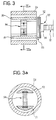
- Figure 3 shows, in longitudinal section, a detail of a third embodiment of the device according to the invention, in which the coupling between the piezoelectric actuating member and the fixed reference body of the valve is achieved by piezoelectric means,
- Figure 3a is a cross-section taken on the line IIIa-IIIa of the device of Figure 3,
- Figure 4 is a block circuit diagram of a control circuit for an actuator device according to the invention, and
- Figure 5 shows a series of time graphs which represent the operation of the actuator device according to the invention.
-
- A piezoelectric actuator device according to a first embodiment of the invention is shown partially and indicated 10 in Figure 1. In this example, a possible application to an on-off control valve for the injection of fuel or diesel fuel is described but this possible use, which is adopted herein for simplicity of discussion, should be understood as purely indicative.
- The actuator device 10 comprises an elongate piezoelectric actuating
member 12 oriented along a longitudinal axis of the device and composed of a plurality (a stack) of elements arranged in succession between a pair ofend electrodes - A
first end 20 of the piezoelectric member is fixed mechanically on a movable, cup-shaped support member 22 and itssecond end 24 is free relative to thesupport member 22 and, in particular, can translate longitudinally as a result of variations in the length of the actuatingmember 12 due to its piezoelectric properties. - The
support member 22, which is made of ferromagnetic material, is housed and can slide axially with slight friction in a coaxial, fixedreference body 26 which is also cup-shaped and made of ferromagnetic material. The possible travel is small and is of the order of the tolerances and of the dimensional variations to be corrected (a few tenths of a millimetre). The sliding is advantageously arranged to take place after lubrication of the parts by means of the fluid controlled, which is caused to enter this region in a "discharge" stage. - The actuating
member 12 carries, at itsfree end 24, aclosure member 30 of the valve which can engage in acorresponding seat 32 in order to regulate the flow of the fluid under control. - The
closure member 30 is normally kept in the closure position by the action, in compression, of aspring 34 arranged between thefree end 24 of the actuatingmember 12 and awall 36 fixed firmly to the fixed body of the valve and having an axial guide hole for the sliding of the stem of the closure member. The closure member is also kept closed by the pressure of the fluid to be controlled, indicated by the arrows in the drawing. - The
fixed reference body 26 also has, on at least a longitudinal portion of its side wall, an electrical winding arranged in a manner such as to form acoaxial locking electromagnet 40. - In this embodiment, the adjustable connection between one end of the piezoelectric actuating
member 12 and thefixed reference body 26 is achieved by electromagnetic means. - In the rest condition, the
closure member 30 is in the closure position. Thespring 34 can keep the closure member in this position even in the absence of fluid pressure, overcoming the frictional forces between thesupport member 22 and the fixedreference body 26 so as to ensure reasonable safety margins. Thesupport member 22 is freely slidable in thefixed reference body 26. - The closure position defined by the action of the
spring 34 and by the fluid pressure takes account of the actual dimensions of the piezoelectric member and of the mechanical components of the valve at rest, as well as of the manufacturing tolerances involved. In dependence on this position, thesupport member 22 reaches a first reference position in thefixed body 26. - When the actuator device is activated, the
energized electromagnet 40 acts to lock thesupport member 22 in its current position relative to thebody 26 by radial attraction and friction. Thesupport member 22 is thus hold firmly to the fixedreference body 26. - The valve is opened by exciting the
piezoelectric member 12 electrically by means of theend electrodes free end 24 to translate relative to theend 20 which is fixed to thebody 26, overcoming the opposing force of thespring 34 and hence - to sum up-moving theclosure member 30 away from theseat 32 and opening the outlet opening of the valve. - The operation of the actuator according to the invention is characterized by a high degree of precision since the deformations in length of the piezoelectric actuating
member 12 are transmitted to thevalve closure member 30 as a control useful for varying its position relative to itsseat 32 and not for also taking up the spurious dimensional variations arising in the device. - The closure member can be returned rapidly to the closure position by cancelling the control of the actuating
member 12 or even by providing a suitable control of opposite sign, without, however, inducing substantial contraction deformations since they are not tolerable; for example, by the piezoelectric material conventionally used (a series of "stacked" discs). - This latter solution may, however, be adopted effectively in the device according to the invention since this device ensures practically zero tolerances at any moment of the operative life of the device.
- The
locking electromagnet 40 advantageously does not require fast response rates and therefore has a low power consumption. - During continuous operation of the actuator device, progressive heating normally takes place, possibly causing dimensional variations of the components. The
locking electromagnet 40 is therefore de-energized periodically so as to permit relative (micrometric) movements between thesupport member 22 of thepiezoelectric member 12 and thefixed reference body 26 such as to take up the spurious dimensional variations occurring in the device. - An example of the controls for the operation and adjustment of the device is shown in the graphs of Figure 5. The upper graph shows, on a time scale, a portion of the control signals for the actuating
member 12 in which two successive stages of actuation (ON) of the valve can be seen. The corresponding lower graph shows a portion of the control signals (energization and de-energization) for thelocking electromagnet 40, for the fine adjustment of the reference position. De-energization (OFF) is brought about in dependence on the dynamics of the system, for example, every 100 valve control pulses. - The ability to adjust the reference position of the actuating
member 12 relative to the fixed body of the valve periodically, even at frequencies greater than that indicated, leads to a further advantage: that is, the fact that themember 12 can be made of materials which have a high degree of mechanical deformation for small control voltages, but which have poor characteristics of accuracy, mechanical stability, and thermal expansion. In particular, this solution opens the way to the use of actuator devices of the type described, with relatively large travel, for controlling the lifting of engine valves. - A second embodiment of the actuator device with adjustable connection achieved by electromagnetic means is shown in Figure 2 in which identical or functionally equivalent elements or components are indicated by the same reference numerals.
- As will be clear to a person skilled in the art, the solution is achieved by a simple reversal of the embodiment of Figure 1. In particular, a simpler closure-member unit is shown, in which the stem does not occupy part of the valve outlet opening. However, in addition to the
compression spring 34 which acts on thefree end 24 of thepiezoelectric actuating member 12 to keep theclosure member 30 in a rest, closure position, this embodiment provides for the use of a second, contactspring 42 for controlling the travel of thesupport member 22 in thefixed reference body 26, keeping the piezoelectric discs of the "stack" always "in contact". - A further embodiment, in which, in contrast, the connection between the actuating
member 12 and thefixed reference body 26 of the valve is achieved by piezoelectric means instead of electromagnetic means is shown in Figures 3 and 3a, with particular reference to the differences with respect to the preferred solutions described above. - The intermediate
movable support member 22 in the connection between the piezoelectric actuatingmember 12 and thefixed reference body 26 of the valve comprises a pair of opposedsliding blocks shaped body 26. The support member also comprises a connectingelement 52 which connects thesliding blocks first end 20 of thepiezoelectric member 12. - According to this embodiment, the adjustable connection is achieved by means of a
piezoelectric locking member 54 arranged diametrally between the slidingblocks locking member 54 owing to the piezoelectric effect must advantageously be greater than the distance which separates the sliding blocks from the side wall of thefixed body 26, taking account of the mechanical tolerances, of any thermal expansion, and of the long-term dimensional stability of the mechanical components involved. - As will be understood from the drawings, the
piezoelectric locking member 54 always acts on theblocks body 26 and stopping any possible sliding of thesupport member 22 by friction, as in a drum braking system. To facilitate the travel of the sliding blocks during locking operations, the connectingelement 52 advantageously has a structure with radial flexibility achieved, for example, by the provision of longitudinal notches. - A further alternative solution (not shown) which is included within the scope of the present invention, provides for the
movable support member 22 to be locked to the fixedbody 26 by means of one or more check members. These members may be fixed firmly to thefixed body 26 or to thesupport member 22 and may advantageously be operated hydraulically, for example, by means of some of the fluid controlled by the valve, used in recirculation. - In the above-described embodiments, the integration of the electronic control for the adjustment of the connection between the
piezoelectric actuating member 12 and the fixedreference body 26 with the electronic control of the actuator device is also important. - Figure 4 is a functional block diagram of a preferred control circuit. The
electrodes piezoelectric actuating member 12 are indicated in thesingle block 60. The valve is actuated by means of electrical excitations induced in the electrodes in the form of a pulse-width-modulated pulse-train produced by agenerator 62 supplied by an electrical supply via the connection l1. Thepulse generator 62 is connected to theelectrode block 60 by means of aswitch 64 which is controlled at a driving input by an injection-control circuit (not shown), via the connection l2. - The
block 66 indicates the circuit module for locking the reference for the actuatingmember 12 according to one of the solutions described (theelectromagnet 40 or the piezoelectric locking member 54), this module also being supplied by the electrical supply, via the connection l1. - The input of the
circuit module 66 is connected to a lockinglogic circuit 68 which receives its supply via the connection l1 and is driven by the injection-control circuit (not shown) via the connection l2, in common with theswitch 64. - According to the preferred solution described, the length of the electrical connections, particularly of the high-voltage connections, is advantageously reduced and logic circuits for controlling the activation of the valve and for the adjustment of the reference system for the actuating member may be formed on a single substrate.
- Naturally, the principle of the invention remaining the same, the forms of embodiment and details of construction may be varied widely with respect to those described and illustrated purely by way of non-limiting example, without thereby departing from the scope of protection of the present invention defined by the appended claims.
Claims (14)
- An actuator device for a control valve, comprising a piezoelectric actuating member (12) for bringing about the movement of a closure member (30) of the valve between an open position and a closure position, in which the actuating member (12) has a reference portion (20) for connection to a fixed portion (26) of the device and a free portion (24) for connection to the closure member (30), the free portion (24) being movable relative to the reference portion (20) as a result of mechanical deformations produced in the actuating member (12) by the piezoelectric effect,
the device being characterized in that the reference portion (20) of the actuating member (12) is controllable selectively between a condition in which it is locked in a reference position and is fixed firmly to the fixed portion (26) of the device, and a free condition in which it is movable relative to the fixed portion (26). - An actuator device according to Claim 1, characterized in that it comprises means (34) for bringing the actuating member (12) to a reference position at rest which corresponds to a rest condition of the valve and relative to which the open and closure positions are defined, and means (40; 50, 51, 54) for locking the reference portion (20) of the actuating member (12) in the reference position thus reached.
- An actuator device according to Claim 2, characterized in that the means for bringing the actuating member (12) to the reference position comprise a reaction spring (34) associated with the fixed portion (36, 26) of the device and acting on the free portion of the member (12) when the member (12) is not electrically excited.
- An actuator device according to Claim 2, characterized in that the reference portion (20) of the actuating member (12) is hold on a support member (22) movable relative to the fixed portion (26) of the device.
- An actuator device according to Claim 4, characterized in that the fixed portion (26) has a cup-shaped portion in the cavity of which the actuating member (12) is arranged axially, and in that the support member (22) can slide axially in the cavity.
- An actuator device according to Claim 5, characterized in that the support member (22) can be locked relative to the fixed portion (26) of the device by magnetic attraction towards the fixed portion.
- An actuator according to Claim 6, characterized in that the locking means comprise an electrical winding (40) associated with the fixed portion (26) and arranged substantially coaxially with the support member (22), the support member (22) being capable of being attracted magnetically radially towards the fixed portion (26) of the device when the winding (40) is energized.
- An actuator device according to Claim 5, characterized in that it is arranged to direct some of the fluid controlled by the valve into a space provided between the support member (22) and the fixed portion (26) of the device, so as to lubricate the portions (22, 26).
- An actuator device according to Claim 5, characterized in that the support member (22) can be locked relative to the fixed portion (26) of the device by friction.
- An actuator device according to Claim 9, characterized in that the locking means comprise at least one pair of opposed sliding blocks (50, 51) associated with the support member (22) and a corresponding piezoelectric locking member (54) arranged diametrally between the blocks (50, 51) for moving the sliding blocks (50, 51) apart to bring them into contact with the fixed portion (26) of the device as a result of mechanical deformations induced in the locking member (54) by the piezoelectric effect.
- An actuator device according to Claim 2, characterized in that the locking means comprise a plurality of check members associated with the fixed portion (26) for engaging the piezoelectric actuating member (12) as a result of an activation control imparted by hydraulic means.
- An actuator device according to any one of the preceding claims, which can be controlled by means of an electronic driver circuit (60-64), characterized in that it also comprises an electronic control circuit (66, 68) for the locking means (40; 50, 51, 54), integrated with the driver circuit (60-64) of the actuator.
- An actuator device according to Claim 12, characterized in that the electronic control circuit (66, 68) is arranged for periodic activation of the locking means (40; 50, 51, 54).
- An actuator device according to Claim 12 or Claim 13, characterized in that it is arranged to direct some of the fluid controlled by the valve towards the electronic control circuits (66, 68) of the locking means (40; 50, 51, 54) and the driver circuit (60-64) of the actuator, so as to enable the circuits (60-64; 66, 68) to be cooled.
Priority Applications (1)
| Application Number | Priority Date | Filing Date | Title |
|---|---|---|---|
| EP05110981A EP1637728B1 (en) | 2000-06-30 | 2001-06-28 | A self-compensating piezoelectric actuator for a control valve |
Applications Claiming Priority (2)
| Application Number | Priority Date | Filing Date | Title |
|---|---|---|---|
| ITTO000653 | 2000-06-30 | ||
| IT2000TO000653A IT1320475B1 (en) | 2000-06-30 | 2000-06-30 | SELF-COMPENSATED PIEZOELECTRIC ACTUATOR FOR A CONTROL VALVE. |
Related Child Applications (1)
| Application Number | Title | Priority Date | Filing Date |
|---|---|---|---|
| EP05110981A Division EP1637728B1 (en) | 2000-06-30 | 2001-06-28 | A self-compensating piezoelectric actuator for a control valve |
Publications (3)
| Publication Number | Publication Date |
|---|---|
| EP1167748A2 true EP1167748A2 (en) | 2002-01-02 |
| EP1167748A3 EP1167748A3 (en) | 2004-01-14 |
| EP1167748B1 EP1167748B1 (en) | 2005-12-14 |
Family
ID=11457879
Family Applications (2)
| Application Number | Title | Priority Date | Filing Date |
|---|---|---|---|
| EP01115559A Expired - Lifetime EP1167748B1 (en) | 2000-06-30 | 2001-06-28 | A self-compensating piezoelectric actuator for a control valve |
| EP05110981A Expired - Lifetime EP1637728B1 (en) | 2000-06-30 | 2001-06-28 | A self-compensating piezoelectric actuator for a control valve |
Family Applications After (1)
| Application Number | Title | Priority Date | Filing Date |
|---|---|---|---|
| EP05110981A Expired - Lifetime EP1637728B1 (en) | 2000-06-30 | 2001-06-28 | A self-compensating piezoelectric actuator for a control valve |
Country Status (6)
| Country | Link |
|---|---|
| US (1) | US6552473B2 (en) |
| EP (2) | EP1167748B1 (en) |
| AT (2) | ATE313012T1 (en) |
| DE (2) | DE60115766T2 (en) |
| ES (1) | ES2252112T3 (en) |
| IT (1) | IT1320475B1 (en) |
Cited By (5)
| Publication number | Priority date | Publication date | Assignee | Title |
|---|---|---|---|---|
| US5246386A (en) * | 1991-03-26 | 1993-09-21 | Omron Corporation | Structure for and method of making a terminal plug |
| WO2003104694A1 (en) * | 2002-06-06 | 2003-12-18 | Caterpillar Inc. | Method and apparatus for seat detection and soft seating in a piezoelectric device actuated valve system |
| WO2006058811A1 (en) * | 2004-11-29 | 2006-06-08 | Robert Bosch Gmbh | Piezoelectric actuator for operating a mechanical component |
| EP1865195A1 (en) * | 2006-06-07 | 2007-12-12 | Robert Bosch Gmbh | Device for injecting fuel |
| EP2833042A1 (en) * | 2013-07-29 | 2015-02-04 | Astrium GmbH | Valve assembly for switching and/or regulating a media flow of an aerospace engine and aerospace engine |
Families Citing this family (14)
| Publication number | Priority date | Publication date | Assignee | Title |
|---|---|---|---|---|
| DE10025997A1 (en) * | 2000-05-25 | 2001-12-06 | Bosch Gmbh Robert | Piezo actuator |
| JP4144171B2 (en) * | 2000-09-14 | 2008-09-03 | コニカミノルタホールディングス株式会社 | Drive device using electro-mechanical transducer |
| US6789777B2 (en) * | 2002-12-02 | 2004-09-14 | Caterpillar Inc | Piezo solenoid actuator and valve using same |
| DE602006005592D1 (en) * | 2005-12-10 | 2009-04-23 | Merck Patent Gmbh | Liquid crystal polymer film with improved stability |
| US8675290B2 (en) * | 2006-02-13 | 2014-03-18 | 3M Innovative Properties Company | Monocular three-dimensional imaging |
| US8082952B2 (en) * | 2008-08-22 | 2011-12-27 | Hamilton Sundstrand Corporation | Piezoelectric bending element actuator for servo valve |
| US10007340B2 (en) | 2009-03-12 | 2018-06-26 | Immersion Corporation | Systems and methods for interfaces featuring surface-based haptic effects |
| US9746923B2 (en) | 2009-03-12 | 2017-08-29 | Immersion Corporation | Systems and methods for providing features in a friction display wherein a haptic effect is configured to vary the coefficient of friction |
| WO2011062910A1 (en) * | 2009-11-17 | 2011-05-26 | Immersion Corporation | Systems and methods for a friction rotary device for haptic feedback |
| HUE027883T2 (en) * | 2013-05-08 | 2016-10-28 | Grieshaber Vega Kg | Vibration level switch |
| KR102312480B1 (en) * | 2016-11-08 | 2021-10-14 | 가부시키가이샤 후지킨 | Valve device, flow control method using the same, and semiconductor manufacturing method |
| JP7113529B2 (en) * | 2017-09-25 | 2022-08-05 | 株式会社フジキン | Valve device, flow control method, fluid control device, flow control method, semiconductor manufacturing equipment, and semiconductor manufacturing method |
| JP7308506B2 (en) * | 2019-01-31 | 2023-07-14 | 株式会社フジキン | VALVE DEVICE, FLOW CONTROL METHOD USING THIS VALVE DEVICE, SEMICONDUCTOR MANUFACTURING METHOD, AND SEMICONDUCTOR MANUFACTURER |
| US11519517B1 (en) * | 2020-04-10 | 2022-12-06 | Meta Platforms Technologies, Llc | Fluidic devices with piezoelectric actuators and related methods |
Citations (5)
| Publication number | Priority date | Publication date | Assignee | Title |
|---|---|---|---|---|
| US4750706A (en) * | 1985-09-24 | 1988-06-14 | Robert Bosch Gmbh | Valve for dosing liquids or gases |
| EP0324452A2 (en) * | 1988-01-11 | 1989-07-19 | Nissan Motor Co., Ltd. | Fuel injection system |
| DE19702066A1 (en) * | 1997-01-22 | 1998-07-23 | Daimler Benz Ag | Piezoelectric injector for fuel injection systems of internal combustion engines |
| DE19854508C1 (en) * | 1998-11-25 | 2000-05-11 | Siemens Ag | Dosing device |
| EP1139441A1 (en) * | 2000-04-01 | 2001-10-04 | Robert Bosch GmbH | Method and apparatus for controlling system parameters, particularly in fuel injection systems |
Family Cites Families (38)
| Publication number | Priority date | Publication date | Assignee | Title |
|---|---|---|---|---|
| US451578A (en) | 1891-05-05 | Car-wheel mold | ||
| US853490A (en) | 1906-10-29 | 1907-05-14 | Ralph H West | Mold for casting chilled rolls. |
| DE352309C (en) | 1920-05-11 | 1922-04-24 | Theodor Weymerskirch | Casting mold with caliber rings for the production of hardened caliber rolls |
| FR611853A (en) | 1926-02-26 | 1926-10-13 | Delattre Et Frouard Reunis Sa | Shell molding of rolling mill rolls |
| US1747223A (en) | 1927-01-17 | 1930-02-18 | Donald J Campbell | Casting and chilling mold |
| DE477287C (en) | 1927-01-29 | 1929-06-05 | Carl Olaf Johannes Broems | Process for the production of composite castings, in particular of rolls with a large surface hardness |
| DE529838C (en) | 1930-05-14 | 1931-07-17 | Ver Stahlwerke Akt Ges | Process for the production of composite castings, in particular of rollers |
| US1850477A (en) | 1931-03-04 | 1932-03-22 | Roth Ernst | Producing metallic ingots |
| DE680515C (en) | 1937-05-28 | 1939-08-30 | Weinberger Eisenwerk | Device for the production of composite castings, in particular chilled cast iron rolls |
| GB520598A (en) | 1938-10-26 | 1940-04-29 | Richard William Bailey | Improvements relating to the production of metal castings |
| FR1100788A (en) | 1953-05-19 | 1955-09-23 | Mold for shell casting | |
| CH415972A (en) | 1964-03-06 | 1966-06-30 | Alusuisse | Die casting process and device for carrying out the process |
| US3265348A (en) | 1964-11-23 | 1966-08-09 | Edmund Q Sylvester | Mold purging apparatus and method |
| NL6905546A (en) | 1969-02-28 | 1970-09-01 | ||
| AT317460B (en) | 1970-09-29 | 1974-08-26 | Gravicast Patent Gmbh | Apparatus for increasing or central pouring casting and method of making a mold for use in this apparatus |
| US3929184A (en) | 1971-09-09 | 1975-12-30 | Rheinstahl Ag | Apparatus for producing blank metal ingots of uniform cross section and in particular steel ingots |
| US3863704A (en) | 1973-01-02 | 1975-02-04 | Freidhelm Kahn | Method of casting by pouring metal from a melt supply through a feeder into a mold |
| US3882942A (en) | 1973-05-24 | 1975-05-13 | Bethlehem Steel Corp | Mold modifications for eliminating freckle defects in roll castings |
| DE2408032C2 (en) | 1974-02-20 | 1982-12-23 | Friedhelm Prof.Dr.-Ing. 6332 Ehringshausen Kahn | Methods and devices for casting and for directing solidification of castings in casting molds |
| FR2295808A1 (en) | 1974-12-24 | 1976-07-23 | Pont A Mousson | LOW PRESSURE CASTING PROCESS AND PLANT IN SAND MOLD |
| JPS5311830A (en) | 1976-07-20 | 1978-02-02 | Gifu Die & Mold Eng | Method of casting aluminium alloy |
| JPS55136556A (en) | 1979-04-13 | 1980-10-24 | Toshiba Corp | Low-pressure casting device |
| GB2080714B (en) | 1980-07-31 | 1984-07-25 | Richards Brinley James | Tilting mould in casting |
| JPS5944365A (en) | 1982-09-07 | 1984-03-12 | Mitsubishi Yuka Yakuhin Kk | 2-phenylalkylthio-4(3h)-quinazolinone derivative |
| JPS6123565A (en) | 1984-07-13 | 1986-02-01 | Sintokogio Ltd | Method and device for low-pressure casting |
| US4629039A (en) * | 1985-01-17 | 1986-12-16 | Nippondenso Co., Ltd | Vehicle braking control apparatus |
| JPS61268558A (en) * | 1985-05-22 | 1986-11-28 | Nippon Soken Inc | Anti-skid hydraulic modulator of braking device for vehicle |
| US4629926A (en) * | 1985-10-21 | 1986-12-16 | Kiwi Coders Corporation | Mounting for piezoelectric bender of fluid control device |
| GB8604386D0 (en) | 1986-02-21 | 1986-03-26 | Cosworth Res & Dev Ltd | Casting |
| GB2187984B (en) | 1986-02-21 | 1989-11-08 | Cosworth Res & Dev Ltd | Method of and apparatus for casting |
| US4875518A (en) | 1987-08-21 | 1989-10-24 | Honda Giken Kogyo Kabushiki Kaisha | Method of and apparatus for low-pressure casting of light metal alloy |
| JP2605054B2 (en) | 1987-08-24 | 1997-04-30 | 本田技研工業株式会社 | Gate cooling method for low pressure casting equipment |
| US4929859A (en) * | 1987-12-25 | 1990-05-29 | Toyota Jidosha Kabushiki Kaisha | Piezoelectric actuator having parallel arrangement of a single piezoelectric element and a pair of displacement magnification arms |
| US4769569A (en) * | 1988-01-19 | 1988-09-06 | Ford Motor Company | Piezoelectric stack motor stroke amplifier |
| JP2637813B2 (en) | 1989-01-18 | 1997-08-06 | 本田技研工業株式会社 | Mold casting method |
| US4993473A (en) | 1990-07-30 | 1991-02-19 | General Motors Corporation | Differential pressure, countergravity casting using mold ingate chills |
| WO1992007674A1 (en) | 1990-11-05 | 1992-05-14 | Comalco Aluminium Limited | Casting of metal objects |
| US5072773A (en) | 1990-11-13 | 1991-12-17 | Cmi International, Inc. | Mold and method for making variable hardness castings |
-
2000
- 2000-06-30 IT IT2000TO000653A patent/IT1320475B1/en active
-
2001
- 2001-06-28 ES ES01115559T patent/ES2252112T3/en not_active Expired - Lifetime
- 2001-06-28 DE DE60115766T patent/DE60115766T2/en not_active Expired - Lifetime
- 2001-06-28 EP EP01115559A patent/EP1167748B1/en not_active Expired - Lifetime
- 2001-06-28 AT AT01115559T patent/ATE313012T1/en not_active IP Right Cessation
- 2001-06-28 AT AT05110981T patent/ATE428855T1/en not_active IP Right Cessation
- 2001-06-28 DE DE60138426T patent/DE60138426D1/en not_active Expired - Lifetime
- 2001-06-28 EP EP05110981A patent/EP1637728B1/en not_active Expired - Lifetime
- 2001-06-29 US US09/893,469 patent/US6552473B2/en not_active Expired - Lifetime
Patent Citations (5)
| Publication number | Priority date | Publication date | Assignee | Title |
|---|---|---|---|---|
| US4750706A (en) * | 1985-09-24 | 1988-06-14 | Robert Bosch Gmbh | Valve for dosing liquids or gases |
| EP0324452A2 (en) * | 1988-01-11 | 1989-07-19 | Nissan Motor Co., Ltd. | Fuel injection system |
| DE19702066A1 (en) * | 1997-01-22 | 1998-07-23 | Daimler Benz Ag | Piezoelectric injector for fuel injection systems of internal combustion engines |
| DE19854508C1 (en) * | 1998-11-25 | 2000-05-11 | Siemens Ag | Dosing device |
| EP1139441A1 (en) * | 2000-04-01 | 2001-10-04 | Robert Bosch GmbH | Method and apparatus for controlling system parameters, particularly in fuel injection systems |
Cited By (6)
| Publication number | Priority date | Publication date | Assignee | Title |
|---|---|---|---|---|
| US5246386A (en) * | 1991-03-26 | 1993-09-21 | Omron Corporation | Structure for and method of making a terminal plug |
| WO2003104694A1 (en) * | 2002-06-06 | 2003-12-18 | Caterpillar Inc. | Method and apparatus for seat detection and soft seating in a piezoelectric device actuated valve system |
| WO2006058811A1 (en) * | 2004-11-29 | 2006-06-08 | Robert Bosch Gmbh | Piezoelectric actuator for operating a mechanical component |
| EP1865195A1 (en) * | 2006-06-07 | 2007-12-12 | Robert Bosch Gmbh | Device for injecting fuel |
| EP2833042A1 (en) * | 2013-07-29 | 2015-02-04 | Astrium GmbH | Valve assembly for switching and/or regulating a media flow of an aerospace engine and aerospace engine |
| US9366352B2 (en) | 2013-07-29 | 2016-06-14 | Astrium Gmbh | Valve assembly for switching and/or regulating a medium flow of an aerospace engine and aerospace engine |
Also Published As
| Publication number | Publication date |
|---|---|
| US20020017833A1 (en) | 2002-02-14 |
| DE60115766D1 (en) | 2006-01-19 |
| US6552473B2 (en) | 2003-04-22 |
| DE60138426D1 (en) | 2009-05-28 |
| ATE313012T1 (en) | 2005-12-15 |
| DE60115766T2 (en) | 2006-08-17 |
| ATE428855T1 (en) | 2009-05-15 |
| EP1637728B1 (en) | 2009-04-15 |
| ITTO20000653A1 (en) | 2001-12-30 |
| EP1167748B1 (en) | 2005-12-14 |
| EP1637728A1 (en) | 2006-03-22 |
| IT1320475B1 (en) | 2003-11-26 |
| ES2252112T3 (en) | 2006-05-16 |
| ITTO20000653A0 (en) | 2000-06-30 |
| EP1167748A3 (en) | 2004-01-14 |
Similar Documents
| Publication | Publication Date | Title |
|---|---|---|
| US6552473B2 (en) | Control valve with a self-compensating piezoelectric actuator | |
| US6702250B2 (en) | Magnetostrictive electronic valve timing actuator | |
| EP1907687B1 (en) | Fuel injector with piezoelectric actuator preload | |
| US4829947A (en) | Variable lift operation of bistable electromechanical poppet valve actuator | |
| EP0829641B1 (en) | A fuel injection device for engines | |
| CA2600323C (en) | Directly actuated valve with a strain-type actuator and a method of operating same | |
| US6991187B2 (en) | Magneto-hydraulic compensator for a fuel injector | |
| EP1035322B1 (en) | Fuel injector | |
| JP2000097127A (en) | Pump-nozzle unit and control unit, and method for controlling pump unit inner-side pressure formation by control unit | |
| JPH07317626A (en) | Hard magnetic valve actuator of fuel injector | |
| US6364221B1 (en) | Electronic fuel injector actuated by magnetostrictive transduction | |
| US7055765B2 (en) | Fuel injection valve | |
| CZ20002743A3 (en) | Electromagnetically controlled valve | |
| US9689360B2 (en) | Actuator | |
| US6274954B1 (en) | Electromagnetic actuator for actuating a gas-exchanging valve | |
| JPS59183180A (en) | Changeover valve controlling run-through of pressure medium | |
| US6091314A (en) | Piezoelectric booster for an electromagnetic actuator | |
| US6789777B2 (en) | Piezo solenoid actuator and valve using same | |
| JP2003512556A (en) | Fuel injection valve | |
| JP2005090422A (en) | Fuel injection valve | |
| JPH10274127A (en) | Fuel injection valve | |
| EP1482570B1 (en) | Thermally compensated piezoelectric assembly | |
| US7080818B2 (en) | Pressure regulating valve for common-rail fuel injection system | |
| PL199631B1 (en) | System for exchanging an internal combustion engine charge and method of operating such system | |
| JPS62199960A (en) | Fuel injection valve |
Legal Events
| Date | Code | Title | Description |
|---|---|---|---|
| PUAI | Public reference made under article 153(3) epc to a published international application that has entered the european phase |
Free format text: ORIGINAL CODE: 0009012 |
|
| AK | Designated contracting states |
Kind code of ref document: A2 Designated state(s): AT BE CH CY DE DK ES FI FR GB GR IE IT LI LU MC NL PT SE TR |
|
| AX | Request for extension of the european patent |
Free format text: AL;LT;LV;MK;RO;SI |
|
| PUAL | Search report despatched |
Free format text: ORIGINAL CODE: 0009013 |
|
| AK | Designated contracting states |
Kind code of ref document: A3 Designated state(s): AT BE CH CY DE DK ES FI FR GB GR IE IT LI LU MC NL PT SE TR |
|
| AX | Request for extension of the european patent |
Extension state: AL LT LV MK RO SI |
|
| RIC1 | Information provided on ipc code assigned before grant |
Ipc: 7F 16K 31/00 B Ipc: 7F 02M 53/04 B Ipc: 7H 01L 41/053 B Ipc: 7F 02M 51/06 B Ipc: 7F 02M 61/16 B Ipc: 7F 16K 35/02 B Ipc: 7F 02M 59/46 A |
|
| 17P | Request for examination filed |
Effective date: 20040708 |
|
| 17Q | First examination report despatched |
Effective date: 20040818 |
|
| AKX | Designation fees paid |
Designated state(s): AT BE CH CY DE DK ES FI FR GB GR IE IT LI LU MC NL PT SE TR |
|
| GRAP | Despatch of communication of intention to grant a patent |
Free format text: ORIGINAL CODE: EPIDOSNIGR1 |
|
| GRAS | Grant fee paid |
Free format text: ORIGINAL CODE: EPIDOSNIGR3 |
|
| GRAA | (expected) grant |
Free format text: ORIGINAL CODE: 0009210 |
|
| AK | Designated contracting states |
Kind code of ref document: B1 Designated state(s): AT BE CH CY DE DK ES FI FR GB GR IE IT LI LU MC NL PT SE TR |
|
| PG25 | Lapsed in a contracting state [announced via postgrant information from national office to epo] |
Ref country code: BE Free format text: LAPSE BECAUSE OF FAILURE TO SUBMIT A TRANSLATION OF THE DESCRIPTION OR TO PAY THE FEE WITHIN THE PRESCRIBED TIME-LIMIT Effective date: 20051214 Ref country code: FI Free format text: LAPSE BECAUSE OF FAILURE TO SUBMIT A TRANSLATION OF THE DESCRIPTION OR TO PAY THE FEE WITHIN THE PRESCRIBED TIME-LIMIT Effective date: 20051214 Ref country code: CH Free format text: LAPSE BECAUSE OF FAILURE TO SUBMIT A TRANSLATION OF THE DESCRIPTION OR TO PAY THE FEE WITHIN THE PRESCRIBED TIME-LIMIT Effective date: 20051214 Ref country code: AT Free format text: LAPSE BECAUSE OF FAILURE TO SUBMIT A TRANSLATION OF THE DESCRIPTION OR TO PAY THE FEE WITHIN THE PRESCRIBED TIME-LIMIT Effective date: 20051214 Ref country code: NL Free format text: LAPSE BECAUSE OF FAILURE TO SUBMIT A TRANSLATION OF THE DESCRIPTION OR TO PAY THE FEE WITHIN THE PRESCRIBED TIME-LIMIT Effective date: 20051214 Ref country code: LI Free format text: LAPSE BECAUSE OF FAILURE TO SUBMIT A TRANSLATION OF THE DESCRIPTION OR TO PAY THE FEE WITHIN THE PRESCRIBED TIME-LIMIT Effective date: 20051214 |
|
| REG | Reference to a national code |
Ref country code: GB Ref legal event code: FG4D |
|
| REG | Reference to a national code |
Ref country code: CH Ref legal event code: EP |
|
| REG | Reference to a national code |
Ref country code: IE Ref legal event code: FG4D |
|
| REF | Corresponds to: |
Ref document number: 60115766 Country of ref document: DE Date of ref document: 20060119 Kind code of ref document: P |
|
| REG | Reference to a national code |
Ref country code: SE Ref legal event code: TRGR |
|
| PG25 | Lapsed in a contracting state [announced via postgrant information from national office to epo] |
Ref country code: GR Free format text: LAPSE BECAUSE OF FAILURE TO SUBMIT A TRANSLATION OF THE DESCRIPTION OR TO PAY THE FEE WITHIN THE PRESCRIBED TIME-LIMIT Effective date: 20060314 Ref country code: DK Free format text: LAPSE BECAUSE OF FAILURE TO SUBMIT A TRANSLATION OF THE DESCRIPTION OR TO PAY THE FEE WITHIN THE PRESCRIBED TIME-LIMIT Effective date: 20060314 |
|
| PG25 | Lapsed in a contracting state [announced via postgrant information from national office to epo] |
Ref country code: PT Free format text: LAPSE BECAUSE OF FAILURE TO SUBMIT A TRANSLATION OF THE DESCRIPTION OR TO PAY THE FEE WITHIN THE PRESCRIBED TIME-LIMIT Effective date: 20060515 |
|
| REG | Reference to a national code |
Ref country code: ES Ref legal event code: FG2A Ref document number: 2252112 Country of ref document: ES Kind code of ref document: T3 |
|
| NLV1 | Nl: lapsed or annulled due to failure to fulfill the requirements of art. 29p and 29m of the patents act | ||
| PG25 | Lapsed in a contracting state [announced via postgrant information from national office to epo] |
Ref country code: IE Free format text: LAPSE BECAUSE OF NON-PAYMENT OF DUE FEES Effective date: 20060628 |
|
| PG25 | Lapsed in a contracting state [announced via postgrant information from national office to epo] |
Ref country code: MC Free format text: LAPSE BECAUSE OF NON-PAYMENT OF DUE FEES Effective date: 20060630 |
|
| REG | Reference to a national code |
Ref country code: CH Ref legal event code: PL |
|
| ET | Fr: translation filed | ||
| PLBE | No opposition filed within time limit |
Free format text: ORIGINAL CODE: 0009261 |
|
| STAA | Information on the status of an ep patent application or granted ep patent |
Free format text: STATUS: NO OPPOSITION FILED WITHIN TIME LIMIT |
|
| 26N | No opposition filed |
Effective date: 20060915 |
|
| REG | Reference to a national code |
Ref country code: IE Ref legal event code: MM4A |
|
| PG25 | Lapsed in a contracting state [announced via postgrant information from national office to epo] |
Ref country code: LU Free format text: LAPSE BECAUSE OF NON-PAYMENT OF DUE FEES Effective date: 20060628 Ref country code: TR Free format text: LAPSE BECAUSE OF FAILURE TO SUBMIT A TRANSLATION OF THE DESCRIPTION OR TO PAY THE FEE WITHIN THE PRESCRIBED TIME-LIMIT Effective date: 20051214 |
|
| PG25 | Lapsed in a contracting state [announced via postgrant information from national office to epo] |
Ref country code: CY Free format text: LAPSE BECAUSE OF FAILURE TO SUBMIT A TRANSLATION OF THE DESCRIPTION OR TO PAY THE FEE WITHIN THE PRESCRIBED TIME-LIMIT Effective date: 20051214 |
|
| PGFP | Annual fee paid to national office [announced via postgrant information from national office to epo] |
Ref country code: SE Payment date: 20120621 Year of fee payment: 12 Ref country code: GB Payment date: 20120622 Year of fee payment: 12 |
|
| PGFP | Annual fee paid to national office [announced via postgrant information from national office to epo] |
Ref country code: ES Payment date: 20120518 Year of fee payment: 12 Ref country code: FR Payment date: 20120713 Year of fee payment: 12 |
|
| PG25 | Lapsed in a contracting state [announced via postgrant information from national office to epo] |
Ref country code: SE Free format text: LAPSE BECAUSE OF NON-PAYMENT OF DUE FEES Effective date: 20130629 |
|
| REG | Reference to a national code |
Ref country code: SE Ref legal event code: EUG |
|
| GBPC | Gb: european patent ceased through non-payment of renewal fee |
Effective date: 20130628 |
|
| REG | Reference to a national code |
Ref country code: FR Ref legal event code: ST Effective date: 20140228 |
|
| PG25 | Lapsed in a contracting state [announced via postgrant information from national office to epo] |
Ref country code: GB Free format text: LAPSE BECAUSE OF NON-PAYMENT OF DUE FEES Effective date: 20130628 |
|
| PG25 | Lapsed in a contracting state [announced via postgrant information from national office to epo] |
Ref country code: FR Free format text: LAPSE BECAUSE OF NON-PAYMENT OF DUE FEES Effective date: 20130701 |
|
| REG | Reference to a national code |
Ref country code: ES Ref legal event code: FD2A Effective date: 20140715 |
|
| PG25 | Lapsed in a contracting state [announced via postgrant information from national office to epo] |
Ref country code: ES Free format text: LAPSE BECAUSE OF NON-PAYMENT OF DUE FEES Effective date: 20130629 |
|
| PGFP | Annual fee paid to national office [announced via postgrant information from national office to epo] |
Ref country code: IT Payment date: 20180611 Year of fee payment: 18 |
|
| PGFP | Annual fee paid to national office [announced via postgrant information from national office to epo] |
Ref country code: DE Payment date: 20180831 Year of fee payment: 18 |
|
| REG | Reference to a national code |
Ref country code: DE Ref legal event code: R119 Ref document number: 60115766 Country of ref document: DE |
|
| PG25 | Lapsed in a contracting state [announced via postgrant information from national office to epo] |
Ref country code: DE Free format text: LAPSE BECAUSE OF NON-PAYMENT OF DUE FEES Effective date: 20200101 Ref country code: IT Free format text: LAPSE BECAUSE OF NON-PAYMENT OF DUE FEES Effective date: 20190628 |