EP1168050A2 - Liquid crystal display device and electronic apparatus using the same - Google Patents
Liquid crystal display device and electronic apparatus using the same Download PDFInfo
- Publication number
- EP1168050A2 EP1168050A2 EP01203413A EP01203413A EP1168050A2 EP 1168050 A2 EP1168050 A2 EP 1168050A2 EP 01203413 A EP01203413 A EP 01203413A EP 01203413 A EP01203413 A EP 01203413A EP 1168050 A2 EP1168050 A2 EP 1168050A2
- Authority
- EP
- European Patent Office
- Prior art keywords
- light
- display device
- display
- polarised
- liquid crystal
- Prior art date
- Legal status (The legal status is an assumption and is not a legal conclusion. Google has not performed a legal analysis and makes no representation as to the accuracy of the status listed.)
- Granted
Links
Images


Classifications
-
- G—PHYSICS
- G02—OPTICS
- G02F—OPTICAL DEVICES OR ARRANGEMENTS FOR THE CONTROL OF LIGHT BY MODIFICATION OF THE OPTICAL PROPERTIES OF THE MEDIA OF THE ELEMENTS INVOLVED THEREIN; NON-LINEAR OPTICS; FREQUENCY-CHANGING OF LIGHT; OPTICAL LOGIC ELEMENTS; OPTICAL ANALOGUE/DIGITAL CONVERTERS
- G02F1/00—Devices or arrangements for the control of the intensity, colour, phase, polarisation or direction of light arriving from an independent light source, e.g. switching, gating or modulating; Non-linear optics
- G02F1/01—Devices or arrangements for the control of the intensity, colour, phase, polarisation or direction of light arriving from an independent light source, e.g. switching, gating or modulating; Non-linear optics for the control of the intensity, phase, polarisation or colour
- G02F1/13—Devices or arrangements for the control of the intensity, colour, phase, polarisation or direction of light arriving from an independent light source, e.g. switching, gating or modulating; Non-linear optics for the control of the intensity, phase, polarisation or colour based on liquid crystals, e.g. single liquid crystal display cells
- G02F1/133—Constructional arrangements; Operation of liquid crystal cells; Circuit arrangements
- G02F1/1333—Constructional arrangements; Manufacturing methods
- G02F1/1335—Structural association of cells with optical devices, e.g. polarisers or reflectors
- G02F1/133528—Polarisers
- G02F1/133536—Reflective polarizers
-
- G—PHYSICS
- G02—OPTICS
- G02F—OPTICAL DEVICES OR ARRANGEMENTS FOR THE CONTROL OF LIGHT BY MODIFICATION OF THE OPTICAL PROPERTIES OF THE MEDIA OF THE ELEMENTS INVOLVED THEREIN; NON-LINEAR OPTICS; FREQUENCY-CHANGING OF LIGHT; OPTICAL LOGIC ELEMENTS; OPTICAL ANALOGUE/DIGITAL CONVERTERS
- G02F1/00—Devices or arrangements for the control of the intensity, colour, phase, polarisation or direction of light arriving from an independent light source, e.g. switching, gating or modulating; Non-linear optics
- G02F1/01—Devices or arrangements for the control of the intensity, colour, phase, polarisation or direction of light arriving from an independent light source, e.g. switching, gating or modulating; Non-linear optics for the control of the intensity, phase, polarisation or colour
- G02F1/13—Devices or arrangements for the control of the intensity, colour, phase, polarisation or direction of light arriving from an independent light source, e.g. switching, gating or modulating; Non-linear optics for the control of the intensity, phase, polarisation or colour based on liquid crystals, e.g. single liquid crystal display cells
- G02F1/133—Constructional arrangements; Operation of liquid crystal cells; Circuit arrangements
- G02F1/1333—Constructional arrangements; Manufacturing methods
- G02F1/1335—Structural association of cells with optical devices, e.g. polarisers or reflectors
- G02F1/1336—Illuminating devices
- G02F1/13362—Illuminating devices providing polarized light, e.g. by converting a polarisation component into another one
-
- G—PHYSICS
- G02—OPTICS
- G02F—OPTICAL DEVICES OR ARRANGEMENTS FOR THE CONTROL OF LIGHT BY MODIFICATION OF THE OPTICAL PROPERTIES OF THE MEDIA OF THE ELEMENTS INVOLVED THEREIN; NON-LINEAR OPTICS; FREQUENCY-CHANGING OF LIGHT; OPTICAL LOGIC ELEMENTS; OPTICAL ANALOGUE/DIGITAL CONVERTERS
- G02F1/00—Devices or arrangements for the control of the intensity, colour, phase, polarisation or direction of light arriving from an independent light source, e.g. switching, gating or modulating; Non-linear optics
- G02F1/01—Devices or arrangements for the control of the intensity, colour, phase, polarisation or direction of light arriving from an independent light source, e.g. switching, gating or modulating; Non-linear optics for the control of the intensity, phase, polarisation or colour
- G02F1/13—Devices or arrangements for the control of the intensity, colour, phase, polarisation or direction of light arriving from an independent light source, e.g. switching, gating or modulating; Non-linear optics for the control of the intensity, phase, polarisation or colour based on liquid crystals, e.g. single liquid crystal display cells
- G02F1/133—Constructional arrangements; Operation of liquid crystal cells; Circuit arrangements
- G02F1/1333—Constructional arrangements; Manufacturing methods
- G02F1/1335—Structural association of cells with optical devices, e.g. polarisers or reflectors
- G02F1/133504—Diffusing, scattering, diffracting elements
-
- G—PHYSICS
- G02—OPTICS
- G02F—OPTICAL DEVICES OR ARRANGEMENTS FOR THE CONTROL OF LIGHT BY MODIFICATION OF THE OPTICAL PROPERTIES OF THE MEDIA OF THE ELEMENTS INVOLVED THEREIN; NON-LINEAR OPTICS; FREQUENCY-CHANGING OF LIGHT; OPTICAL LOGIC ELEMENTS; OPTICAL ANALOGUE/DIGITAL CONVERTERS
- G02F1/00—Devices or arrangements for the control of the intensity, colour, phase, polarisation or direction of light arriving from an independent light source, e.g. switching, gating or modulating; Non-linear optics
- G02F1/01—Devices or arrangements for the control of the intensity, colour, phase, polarisation or direction of light arriving from an independent light source, e.g. switching, gating or modulating; Non-linear optics for the control of the intensity, phase, polarisation or colour
- G02F1/13—Devices or arrangements for the control of the intensity, colour, phase, polarisation or direction of light arriving from an independent light source, e.g. switching, gating or modulating; Non-linear optics for the control of the intensity, phase, polarisation or colour based on liquid crystals, e.g. single liquid crystal display cells
- G02F1/133—Constructional arrangements; Operation of liquid crystal cells; Circuit arrangements
- G02F1/1333—Constructional arrangements; Manufacturing methods
- G02F1/1335—Structural association of cells with optical devices, e.g. polarisers or reflectors
- G02F1/133528—Polarisers
- G02F1/133545—Dielectric stack polarisers
-
- G—PHYSICS
- G02—OPTICS
- G02F—OPTICAL DEVICES OR ARRANGEMENTS FOR THE CONTROL OF LIGHT BY MODIFICATION OF THE OPTICAL PROPERTIES OF THE MEDIA OF THE ELEMENTS INVOLVED THEREIN; NON-LINEAR OPTICS; FREQUENCY-CHANGING OF LIGHT; OPTICAL LOGIC ELEMENTS; OPTICAL ANALOGUE/DIGITAL CONVERTERS
- G02F1/00—Devices or arrangements for the control of the intensity, colour, phase, polarisation or direction of light arriving from an independent light source, e.g. switching, gating or modulating; Non-linear optics
- G02F1/01—Devices or arrangements for the control of the intensity, colour, phase, polarisation or direction of light arriving from an independent light source, e.g. switching, gating or modulating; Non-linear optics for the control of the intensity, phase, polarisation or colour
- G02F1/13—Devices or arrangements for the control of the intensity, colour, phase, polarisation or direction of light arriving from an independent light source, e.g. switching, gating or modulating; Non-linear optics for the control of the intensity, phase, polarisation or colour based on liquid crystals, e.g. single liquid crystal display cells
- G02F1/133—Constructional arrangements; Operation of liquid crystal cells; Circuit arrangements
- G02F1/1333—Constructional arrangements; Manufacturing methods
- G02F1/1335—Structural association of cells with optical devices, e.g. polarisers or reflectors
- G02F1/13356—Structural association of cells with optical devices, e.g. polarisers or reflectors characterised by the placement of the optical elements
- G02F1/133567—Structural association of cells with optical devices, e.g. polarisers or reflectors characterised by the placement of the optical elements on the back side
Definitions
- the present invention relates to a display device, and specifically to a display device using a liquid crystal as variable transmission polarisation axis means.
- the present invention relates to a so-called transflective liquid crystal display device functioning as a transmissive liquid crystal display device when a light source is turned on and functioning as a reflective liquid crystal display device when the light source is turned off.
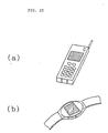
- the present invention relates to electronic apparatus comprising the display device as a display unit, such as a watch, an electronic handbook, a personal computer, and the like.
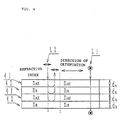
- a conventional liquid crystal display device comprising a variable transmission polarisation axis optical element 2605 in which the polarisation axis of a liquid crystal is variable, such as a TN (Twisted Nematic) liquid crystal, STN (Super-Twisted Nematic) crystal, or the like, has a structure in which the variable transmission polarisation axis optical element 2605 is sandwiched between two polarisation 2601 and 2606, as shown in Fig. 26. Therefore, the conventional liquid crystal display device has a low efficiency of light utilisation, and particularly, a reflective type has a problem with dark display.
- TN Transmission Nematic
- STN Super-Twisted Nematic
- WO 95/17692 discloses a display device with brightness enhancement including a multiple layer reflective polariser placed between an optical cavity and an LCD module.
- an object of the present invention is to provide a display device using a variable transmission polarisation axis optical element in which the display device is capable of providing a bright display.
- a thin reflecting plate is formed, or an opening is provided, thereby decreasing reflectance at reflective display. That is to say, in a transflective type device, brightness of the reflective display is sacrificed.
- another object of the present invention is to provide a transflective liquid crystal display device having a bright reflective display comprising a light source provided on the back of a liquid crystal display device so as to permit not only reflective display by external light but also display by transmitted light from the light source provided on the back of the device.
- the display when external light is incident on the display device with the light source turned on, due to positive-negative reversal, the display is sometimes hard to see.
- a further object of the present invention is to provide a display device in which the display is not hard to see in the case of positive-negative reversal.
- a display device comprises variable transmission polarisation axis means having a variable transmission polarisation axis, first and second polarised light separating means, disposed on both sides of and sandwiching the variable transmission polarisation axis means, and a light source disposed opposite to the variable transmission polarisation axis means with respect to the second polarised light separating means;
- the first polarised light separating means is a polarised light separating means in which of light incident on a first side of the first polarised light separating means, a linearly polarised light component in a first predetermined direction is transmitted as linearly polarised light in the first predetermined direction to a second side opposite to the first side; of light incident on the first side of the first polarised light separating means, a linearly polarised light component in a second direction different from the first predetermined direction is not transmitted to the second side; of light incident on the second side of the first polarised light separating means, a linearly polarised light component
- two display states i.e., a first display state created by the light reflected from the second polarised light separating means and a second display state where the light transmitted through the second polarised light separating means is absorbed by the light source side, are obtained according to the state of the transmission polarisation axis of the variable transmission polarisation axis means, to operate the display device as a reflective display device.
- the first display state is a display state created by the light reflected from the second polarised light separating means and thus produces a bright display.
- two display states i.e., a third display state created by the light transmitted through the first polarised light separating means, and a fourth display state where no light is transmitted through the first polarised light separating means, are obtained according to the state of the transmission polarisation axis of the variable transmission polarisation axis means, to obtain a transmissive display.
- the second polarised light separating means is preferably a polarised light separating means in which for light over substantially the whole wavelength range of the visible light region, of light incident on the variable transmission polarisation axis means side, a linearly polarised light component in the third predetermined direction is transmitted to the light source side, and a linearly polarised light component in the fourth predetermined direction different from the third predetermined direction is reflected to the variable transmission polarisation axis means side; and for light incident on the light source side which is light over substantially the whole wavelength range of the visible light region, linearly polarised light in the third predetermined direction can be emitted to the variable transmission polarisation axis means side.
- the first to fourth display states are obtained for light over substantially the whole wavelength range of the visible light region, and a transparent or white display can be obtained in the first and third display states.
- the second polarised light separating means is preferably polarised light separating means in which of light incident on the variable transmission polarisation axis means side, a linearly polarised light component in the third predetermined direction is transmitted as linearly polarised light in the third predetermined direction to the light source side.
- the second polarised light separating means is preferably polarised light separating means comprising films laminated in a plurality of layers in which the refractive indexes of the plurality of layers are the same between each adjacent layer in the third predetermined direction, and different in the fourth predetermined direction.
- the first polarised light separating means preferably comprises a polariser.
- the variable transmission polarisation axis means preferably comprises a liquid crystal panel, particularly a TN liquid crystal panel, an STN liquid crystal panel, an F-STN liquid crystal panel or an ECB liquid crystal panel.
- the STN liquid crystal panel is an STN liquid crystal panel using a colour compensation optical anisotropic material, such as an F-STN (Film compensated Super-Twisted nematic) liquid crystal panel, or an STN liquid crystal panel positively using the birefringenceof, a liquid crystal without using a colour compensation optical anistropic material.
- reflection from the surface of the light source can be suppressed by darkening the surface colour of the light source. Consequently, it is possible to decrease the quantity of the light transmitted through the optical element and returned by reflection from the light source, thereby suppressing a decrease in contrast.
- an optical element is further provided between the second polarised light separating means and the light source, which can absorb light from the second polarised light separating means side, and transmits light from the light source to the second polarised light separating means side.
- the two display states which are the first display state created by the light reflected from the second polarised light separating means and the second display state where the light transmitted through the second polarised light separating means is absorbed by the light source and the optical element in accordance with the state of the transmission polarisation axis of the variable transmission polarisation axis means, and thereby a reflective display can be obtained.
- the second display state light is absorbed by not only the light source but also the optical element, to cause a darker display.
- the two display states i.e., the third display state created by the light transmitted through the first polarised light separating means, and the fourth display state where no light is transmitted through the first polarised light separating means, are obtained to realise a transmissive display.
- the optical element is preferably an optical element which absorbs light over substantially the whole wavelength range of the visible region, and more preferably is a black absorber.
- the optical element may have openings. By providing such openings, light from the light source can be transmitted to the second polarised light separating means side through the openings.
- the two display states i.e., the first display state created by the light reflected from the second polarised light separating means, and the second display state where light transmitted through the second polarised light separating means is absorbed by the optical element, are obtained, as described above.
- the optical element is an optical element capable of absorbing light from the second polarised light separating means side and of transmitting light from the light source to the second polarised light separating means side, in the second display state, depending on the structure of the optical elements, light is not completely absorbed by the optical element, with some light transmitted through the optical element, reflected by the light source or the like, and again transmitted through the optical element to return to the variable transmission polarisation axis means side, causing a decrease in contrast.
- the quantity of the light transmitted through the optical element and returned through the optical element can be decreased by limiting the ratio of the openings to the optical element, thereby suppressing a decrease in contrast.
- the area ratio of the openings to the optical element is preferably 5 to 30%.
- the quantity of the light transmitted through the optical element and returned by reflection by the liquid source can also be decreased by setting the distance between the optical element and the light source to be larger than the diameter of the openings, thereby suppressing a decrease in contrast.
- the optical element my comprise a light absorber in a grey translucence state so as to permit absorption of light from the second polarised light separating means side, and transmission of light from the light source to the second polarised light separating means side.
- the light absorber in a grey translucence state preferably has a transmittance of 10 to 80% to the light over substantially the whole wavelength range of the visible light region.
- the transmittance is more preferably 10 to 30%.
- the optical element preferably comprises a polariser wherein the transmission axis thereof is deviated from that of the second polarised light separating means. This enables absorption of light from the variable transmission polarisation axis means side and transmission of light from the light source to the variable transmission polarisation axis means side.
- the optical element preferably comprises a light scattering member capable of changing the polarisation state of light incident on the optical element and of emitting light therefrom.
- the two display states i.e., the first display state created by the light reflected by the second polarised light separating means, and the second display state where light transmitted through the second polarised light separating means cannot be transmitted through a polarised light separator due to removal of the polarisation state by scattering a plate, are obtained according to the state of the transmission polarisation axis of the variable transmission polarisation axis means, and therefore a reflective display device can be formed.
- the second display state light is not only absorbed by the light source but also scattered by the optical element to obtain a darker display.
- the two display states i.e., the third display state created by the light transmitted through the first polarised light separating means, and the fourth display state where no light is transmitted through the first polarised light separating means, are obtained in accordance with the state of the transmission polarisation axis of the variable transmission polarisation axis means, to obtain a transmissive display.
- means for converging light from the light source to the front of the display device is further provided.
- the display When seeing the reflective display provided by external light, the display is generally seen at a position which is at an angle with the normal to the front of the display device. This is because if the display is seen from the direction normal to the front of the display device, external light incident on the display device is hindered by the observer, and thus the reflective display becomes dark.
- the display obtained by transmitted light from the light source when seeing the display obtained by transmitted light from the light source, the display is generally seen from the direction normal to the front of the display device, and thus the display obtained by transmitted light from the light source can be bright by providing means for converging light from the light source to the front of the display device. As a result, a transmissive display obtained by the light from the light source can easily be seen in the direction normal to the front of the display device.
- a light diffusion means is further provided. This can bring about a white display in the first display state by reflection of external light from the second polarised light separating means and the third display state by transmission of light from the light source through the first polarised light separating means.
- the light source may comprise a cold cathode tube capable of emitting white light, and a light guide plate capable of emitting white light incident from the cold cathode tube to the second polarised light separating means side.
- the two display states which are the third display state created by the light transmitted through the first polarised light separating means and the fourth display state where no light is transmitted through the first polarised light separating means, can be obtained to form transmissive display, as described above.
- a white display is obtained in the third display state when the state of the transmission polarisation axis of the variable transmission polarisation axis means is on, and a black display is obtained in the fourth display state when the state of the transmission polarisation axis of the variable transmission polarisation axis means is off, in accordance with the structure of the display device.
- the external light when external light is incident on the first polarised light separating means side of the display device, the external light produces a black display in the second display state with the transmission polarisation axis of the variable transmission polarisation axis means turned on, and produces a white display in the first display state with the transmission polarisation axis of the variable transmission polarisation axis means turned off.
- an LED capable of emitting light in the predetermined wavelength region to the second polarised light separating means side, or an EL element capable of emitting light in the predetermined wavelength region is preferably used for colouring light from the light source, thereby obtaining a colour display on a grey background and making it easy to see a display obtained by the light from the light source.
- the light source preferably comprises a first LED capable of emitting light in a first predetermined wavelength range, and a second LED capable of emitting light in a second predetermined wavelength range different from the first predetermined wavelength range.
- the light source preferably comprises a first EL element capable of emitting light in a third predetermined wavelength range, and a second EL element capable of emitting light in a fourth predetermined wavelength range different from the third predetermined wavelength range.
- the first and second LED or the first and second EL elements correspond to respective character display portions to obtain different display colours in the respective character display portions, thereby usefully widening the selection range of design possibilities.
- the light source preferably comprises an LED capable of emitting light in a predetermined wavelength region, and a light guide plate capable of emitting light in the predetermined wavelength region to the second polarised light separating means side.
- the arrangement position of the LED can be relatively freely determined, thereby widening the range of design possibilities and making the light uniform for emitting to the second polarised light separating means side.
- the light guide plate preferably has a first light guide region where light in a first predetermined wavelength range is incident from the first LED and emitted to the second polarised light separating means side, and a second light guide region where light in a second predetermined wavelength range is incident from the second LED and emitted to the second polarised light separating means side, with light shielding means polarised between the first light guide region and the second light guide region.
- a coloured layer capable of transmitted or reflecting light in a predetermined wavelength region, and of absorbing light at wavelengths out of the predetermined wavelength region may be provided between the light source and the second polarised light separating means.
- a white light source such as a cold cathode tube may be used as the light source.
- the above-described LED or EL element may be used.
- the coloured layer preferably has a first coloured region capable of reflecting or transmitting light in a first predetermined wavelength range, and a second coloured region capable of transmitting or reflecting light in a second predetermined range different from the first predetermined wavelength range, and is able to absorb light at wavelengths out of the first or second predetermined wavelength range.
- the first and second coloured regions correspond to respective character display portions to obtain different display colours in the respective character display portions, thereby widening the range of selection of design possibilities.
- a transflective plate which can transmit light from the light source to the coloured layer side, reflect light which is incident on the coloured layer from the second polarised light separating means side and is transmitted through the coloured layer, and emit the light to the coloured layer side, is further provided.
- a transflective plate a mirror reflecting plate having openings provided therein can be used.
- the two display states which are the first display state created by the light reflected by the second polarised light separating means, and the second display state created by the light transmitted through the second polarised light separating means and reflected by the coloured layer, and light transmitted through the coloured layer and then reflected by the reflecting plate, are obtained according to the state of the transmission polarisation axis of the variable transmission axis means, to form a reflective display device.
- the purity of colour is increased due to the presence of the reflecting plate.
- An electronic apparatus of the present invention comprises the above display device as a display unit.
- Fig. 1 is a sectional view of a display device in accordance with a first embodiment of the present invention
- Fig. 2 is a schematic sectional view illustrating the principle of display of the display device in accordance with the first embodiment of the present invention.
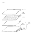
- a display 100 of this embodiment is a display device with a so-called transflective function which is capable of not only reflective display using reflection of external light in a place where external light is present, but also transmission display using light from a light source in a place where external light is absent.
- a TN liquid crystal panel 10 is used as a variable transmission polarisation axis optical element.
- a TN liquid crystal 13 is held between two glass plates 11 and 12, and a plurality of character display portions (not shown in the drawing) are provided to enable character display.
- a polariser 14 On the upper side of the TN liquid crystal panel 10 is provided a polariser 14.
- a light scattering member 15, a polarised light separator 16, and a light source 17 On the lower side of the TN liquid crystal panel 10 are provided a light scattering member 15, a polarised light separator 16, and a light source 17 in this order.
- a TAB substrate (not shown in the drawing) provided with a driver IC is connected to the TN liquid crystal panel 10 to form the display device.
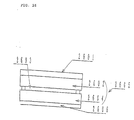
- Fig. 4 is a schematic drawing showing the configuration of the polarised light separator 16 used in this embodiment, and is a drawing illustrating the operation of the polarised light separator 16 shown in Fig. 3.
- the polarised light separator 16 has a structure in which two layers 41 (A layer) and 42 (B layer) are alternately laminated in a plurality of layers.
- the refractive index (n AX ) of the A layers 41 in the X axis direction is different from the refractive index (n BX ) of the B layers 42 in the X axis direction
- the refractive index (n AX ) of the A layers 41 in the Y axis direction is substantially the same as the refractive index (n BY ) of the B layers 42 in the Y axis direction.
- linearly polarised light in the Y axis direction is transmitted through the polarised light separator 16 because the refractive index of the A layers 41 is substantially the same as the reflective index of the B layers in the polarised light separator 16.
- the thickness of the A layers 41 in the Z axis direction is t A
- the thickness of the B layers 41 is t B
- the polarised light separator 16 Since the thickness of the A layers 41 and the thickness of the B layers 42 in the Z axis direction varies, of light incident on the polarised light separator 16 over a wide range of the visible wavelength region, the polarised light separator 16 reflects linearly polarised light in the X axis direction.
- oriented polyethylene napthalate PET; polyethylene naphthalate
- coOEN copolyester of napthalene dicarboxylic acid and terephthalic or isothalic acid
- materials of the polarised light separator 16 used in the present invention are not limited to these materials, and materials can be appropriately selected.
- Such a polarised light separator is disclosed in detail as a reflective polariser in Unexamined International Patent Applications (International Application No. WO/95/27819 and WO95/17692).
- the above polarised light separator is used, besides the polarised light separator, a separator comprising a cholesteric liquid crystal layer held between ⁇ /4 plates, a separator using the angle of polarisation (in the manner described in SID 92DIGEST pp. 427-429), a separator using hologram, and the like have the same function as the above polarised light separator, and may be used for the display device of this embodiment.
- the external light when external light is incident on the display device 100, the external light is changed to linearly polarised light parallel to the plane of the drawing (hereinafter the plane of the drawing will simply be referred to as "the drawing") by the polariser 14, and then the direction of polarisation is rotated 90° by the TN liquid crystal 13 to form linearly polarised light perpendicular to the drawing.
- the linearly polarised light perpendicular to the drawing is reflected by the polarised light separator 16, and then the direction of polarisation is rotated 90° by the then TN liquid crystal 13 to form linearly polarised light parallel to the drawing, which is emitted as linearly polarised light parallel to the drawing from the polariser 14.
- the display device 100 when external light is incident on the display device 100, the external light is changed to linearly polarised light parallel to the drawing, and then transmitted through the TN liquid crystal 13 without change in the direction of polarisation, and the polarised light separator 16 is also transmitted without change in the direction of polarisation to reach the light source 17. Since most of the light which reaches the light source 17 is transmitted through the light source or absorbed thereby, the display becomes dark.
- the display device 100 of this embodiment is a reflective display device with a so-called transflective function, which is capable of not only reflective display using reflection of external light at a place with external light, but also transmissive display using light from the light source 17 at a place without external light.
- the scattering plate used in the display device of this embodiment a scattering plate capable of emitting incident light without removing the state of polarisation to the utmost. Since this scattering plate has the function to scatter and cloud the light emitted from the scattering plate, a display device with a cloudy display (white display) is obtained. In contrast, removal of the scattering plate 15 from the configuration produces a display device with a glossy display. Therefore, the scattering plate may be selected in accordance with application of the display device.
- Figs. 5 to 9 respectively show display devices using various light sources in accordance with this embodiment of the present invention. In this embodiment, any one of the light sources shown in Figs. 5 to 8 can be used.
- the light source used in the display device shown in Fig. 5 comprises a cold cathode tube 50 as a light source and a light guide plate 51.
- a light guide plate 51 a light guide plate having the function to absorb light when the cold cathode tube 50 is turned off is used.
- the display where external light including visible wavelength components having a plurality of colours is incident i.e., a reflective display, becomes a black display in the voltage applied portion and becomes a white display in the voltage unapplied portion, respectively.
- a transmissive display with the light from the light source becomes a display having the colour of the light emitted from the cold cathode tube, i.e., a white display, in the voltage applied portion, and becomes a black display in the voltage unapplied portion.
- the light source used for the display device shown in Fig. 6 comprises an LED 60 which emits light at the wavelength corresponding to red as light source, and a light guide plate 61.
- a reflective display becomes a black display in the voltage applied portion and becomes a white display in the voltage unapplied portions, respectively.
- a transmissive display using light from the light source becomes a display having the colour of the light emitted from the LED 60, i.e., a red display, in the voltage applied portion, and becomes a black display in the voltage unapplied portion.
- a dark display is obtained in the voltage unapplied portion and a bright display is obtained in the voltage applied portion, respectively, to form a transmissive display.
- a bright display is obtained in the voltage unapplied portion and a dark display is obtained in the voltage applied portion, respectively, due to the external light.
- both the voltage unapplied portion and the voltage applied portion for example, when a display with transmitted light from the light source 17 is a bright display, a grey display is obtained due to addition of a reflective dark display by external light, and when a display with transmitted light from the light source 17 is a dark display, a grey display is obtained due to the addition of a reflective bright display by external light, to cause so-called positive-negative reversal and sometimes make the display hard to see.
- the display is significantly easy to see as compared with a simple black-and-white display.
- the LED 60 which emits light having the wavelength corresponding to red is used in Fig. 6, but an LED which emits light having the wavelength corresponding to a colour other than red may be used.
- the light source used for the display device shown in Fig. 7 comprises an EL element 70 as a light source, which emits light having the wavelength of green.
- a reflective display becomes a black display in the voltage applied portion and becomes a white display in the voltage unapplied portion, respectively.
- a transmissive display by the light from the light source becomes a display having the colour of the light emitted from the EL element 70, i.e., a green display, in the voltage applied portion, and becomes a black display in the voltage unapplied portion.
- the EL element 70 which emits light having the wavelength of green is used in Fig. 7, but, of course, an EL element which emits light having the wavelength of a colour other than green may be used.
- the light source used for the display device shown in Fig. 8 comprises as light sources an LED 81 which emits light having the wavelength of red, and an LED 82 which emits light having the wavelength of blue, both LEDs being disposed on the side of a light guide plate 83.
- the light guide plate is partitioned by a reflecting plate 84 into regions corresponding to the LEDs so as to not to mix light having the wavelengths emitted from the respective light guide plates.
- the LEDs are arranged so that the emitted lights correspond to a plurality of character display portions 85 and 86 formed in the liquid crystal panel. In use of the light source shown in Fig.
- a reflective display becomes a black display in the voltage applied portion and becomes a white display in the voltage unapplied portion, respectively.
- a transmissive display with the light from the light source becomes a display having the colour of the light emitted from each of the LEDs in the corresponding character display portion, i.e., a red or blue display, in the voltage applied portion, and becomes a black display in the voltage unapplied portion.
- the LED which emits light having the wavelength of red and the LED which emits light having the wavelength of blue are used, but, of course, an LED which emits light having the wavelength of a colour other than these colours may be used, and combinations may be appropriately selected according to application.
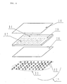
- the light source used for the display device shown in Fig. 9 comprises a plurality of LEDs 91 which emit light having the wavelength of red, and a plurality of LEDs 92 which emit light having the wavelength of blue, with the LEDs arranged as a group for each of the colours.
- the light source shown in Fig. 9 has no light guide plate. Further, the LED groups are arranged so that the emitted lights respectively correspond to a plurality of character display portions formed in the liquid crystal panel.
- a reflective display becomes a black display in the voltage applied portion and becomes a white display in the voltage unapplied portion, respectively.
- a transmissive display by the light from the light source becomes a display having the colour of the light emitted from each of the LED groups respectively corresponding to the character display portions, i.e., a red or blue display, in the voltage applied portion, and becomes a black display in the voltage unapplied portion.
- the light source shown in Fig. 9 is turned on at incidence of external light, light emitted from each of the LED groups can be seen to make the display greyish red or blue in each of the character display portions in the voltage applied portion, and external light reflected by the polarised light separator can be seen to make the display grey in the voltage unapplied portion.
- the LED 91 which emits light having the red wavelength and the LED 92 which emits light having the blue wavelength are used in Fig. 9, but, of course, LEDs which emits light having the wavelength of a colour other than these colours may be used, and the combination can be appropriately selected.
- Fig. 10 is a sectional view of a display device in accordance with a second embodiment of the present invention
- Fig. 11 is a schematic sectional view illustrating the principle of display of the display device in the second embodiment of the invention.
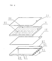
- the display device 1000 of this embodiment is a reflective display device with a so-called transflective function, which is capable of not only reflective display using reflection of external light at a place with external light, but also transmissive display using light from the light source at a place without external light.
- a TN liquid crystal panel 10 is used as a variable transmission polarisation axis optical element.
- a TN liquid crystal 13 is held between two glass plates 11 and 12, and a plurality of character display portions (not shown in the drawing) are provided to enable character display.
- a polariser 14 On the upper side of the TN liquid crystal panel 10 is provided a polariser 14.
- a light scattering member 15 On the lower side of the TN liquid crystal panel 10 are provided a light scattering member 15, a polarised light separator 101, a light absorber 102, and a light source 17 in this order.
- the light absorber 102 is black and has a plurality of openings 103 at a predetermined area density.
- a TAB substrate (not shown in the drawing) provided with a driver IC is connected to the TN liquid crystal panel 10 to form the display device.
- the polarised light separator 101 comprises a (1/4) ⁇ plate 104 and a cholesteric liquid crystal layer 105.
- the cholesteric liquid crystal layer 105 is illuminated with light having the same wavelength as the pitch of the liquid crystal and reflects circularly polarised light with the same direction of rotation as the liquid crystal, transmitting other light. Therefore, for example, when a cholesteric liquid crystal having a pitch of 5000 angstroms and counterclockwise rotation is used for the cholesteric liquid crystal layer 105, a device is obtained in which left-handed circularly polarised light having a wavelength of 5000 angstroms is reflected, and right-handed circularly polarised light and light having other wavelengths are transmitted.
- a cholesteric liquid crystal having counterclockwise rotation and changing the pitch thereof in the cholesteric liquid crystal over the whole wavelength range of visible light an element is obtained which reflects left-handed circularly polarised light not only for monochrome light but also over the whole range of bright colour light, and transmits right-handed circularly polarised light.
- a cholesteric liquid crystal having counterclockwise rotation is used for the cholesteric liquid crystal layer 105, and the pitch thereof is changed in the cholesteric liquid crystal over the whole wavelength range of visible light.
- the polarised light separator 101 comprising the combination of the cholesteric liquid crystal layer 105 and the (1/4) ⁇ plate 104
- the light is changed to left-handed circularly polarised light by the (1/4) ⁇ plate 104, reflected by the cholesteric liquid crystal layer 105, changed again to linearly polarised light in the predetermined first direction by the (1/4) ⁇ plate 104, and then emitted.
- the polarised light separator 101 comprising the combination of the cholesteric liquid crystal layer 105 and the (1/4) ⁇ plate 104 is a polarised light separating means in which of light incident from the (1/4) ⁇ plate 104 side, a linearly polarised light component in the predetermined second direction is transmitted, and a linearly polarised light component in the first direction perpendicular to the predetermined second direction is reflected, and for light incident on the cholesteric liquid crystal layer 105 side, linearly polarised light in the second direction can be emitted to the (1/4) ⁇ plate 104 side.
- polarised light separators having the above function include a separator comprising films laminated in multilayers (of the type disclosed in USP 4,974,219), a separator for separating into reflective polarised light and transmissive polarised light using Brewster angle ( in the manner described in SID 92DIGEST pp. 427-429), a separator using a hologram, and the polarised light separator described above in the first embodiment with reference to Figs. 3 and 4, i.e., the separator disclosed in Unexamined International Patent Applications (International Application Nos. WO95/27819 and WO95/17692).
- the direction of polarisation is rotated 90° by the TN liquid crystal 13 to form linearly polarised light parallel to the drawing, which is emitted as linearly polarised light parallel to the drawing from the polariser 14.
- the light scattering member 15 is provided between the polarised light separator 101 and the TN liquid crystal panel 10, light reflected by the polarised light separator 101 is changed from a mirror state to a bright colour state.
- the external light when external light is incident on the display device 1000, the external light is changed to linearly polarised light parallel to the drawing by the polariser 14, and then transmitted through the TN liquid crystal 13 without changing the direction of polarisation.
- the linearly polarised light is changed to right-handed circularly polarised light by the (1/4) ⁇ plate 104, and transmitted through the cholesteric liquid crystal layer 105.
- the right-handed circularly polarised light transmitted through the cholesteric liquid crystal layer 105 is absorbed by the black light absorber 102 to obtain a dark display.
- the display device 1000 of this embodiment is a reflective display device with a so-called transflective function, which is capable of not only a bright reflective display using reflection of external light at a place with external light, but also a transmissive display using light from the light source 17 at a place with external light.
- the scattering plate 15 used in the display device of this embodiment a scattering plate capable of emitting incident light without removing the state of polarisation to the utmost is used. Since this scattering plate has the function to scatter and cloud the light emitted from the scattering plate, a display device with a cloudy display (white display) is obtained. In contrast, removal of the scattering plate 15 from the configuration produces a display device with a glossy display. Therefore, the scattering plate may be selected in accordance with application of the display device.
- the two display states i.e., a bright display by the light reflected by the polarised light separator 101, and a dark display where light transmitted through the polarised light separator 101 is absorbed by the light absorber 102, are obtained, as described above.
- the light absorber 102 is a black light absorber to absorb light from the polarised light separator 101, and has a plurality of the openings 103 through which light can be transmitted, in the dark display state, light is not completely absorbed by the light absorber 102, but some light is transmitted through the openings 103 of the light absorber 102, reflected by the light source or the like, again transmitted through the openings 103 of the light absorber 102, and returned to the TN liquid crystal panel 10 side, causing a decrease in contrast.
- the area ratio of the openings 103 to the light absorber 102 is preferably limited to decrease the amount of the light which is transmitted through the openings 103 of the light absorber 102, reflected by the light source 17 or the like, and returned through the openings 103 of the light absorber 102, thereby suppressing a decrease in contrast.
- a black light absorber having the plurality of openings 103 is used as the light absorber 102
- a light absorber in a grey translucence state can also be used for absorbing light from the polarised light separator 101 side and for transmitting light from the light source to the polarised light separator 101 side.
- the openings need not be provided.
- light diffusion film D202 produced by Tsujimoto Denki Seisakusho
- the like can be used as the light absorber in a grey translucence state.
- the black light absorber having the plurality of openings 103 is used as the light absorber 102
- a polariser having an absorption axis shifted from that of the polarised light separator 101 can be used in place of the light absorber 102. In this way, with the polarised light separator 101 and the polariser having an absorption axis shifted from that of the polarised light separator 101, light from the TN liquid crystal panel 10 side can be absorbed and light from the light source 17 can be transmitted to the TN liquid crystal panel 10 side.
- the various light sources shown in Figs. 1 to 9 and described in the first embodiment can be used.
- the operation and advantages are the same as the first embodiment, and thus description thereof is omitted.
- Fig. 12 is a schematic sectional view illustrating a display device in accordance with a third embodiment of the invention.
- the polarised light separator 101 comprising the (1/4) ⁇ plate 104 and the cholesteric liquid crystal layer 105 is used.
- This embodiment is different from the second embodiment in that a polarised light separator 121 comprising a (1/4) ⁇ plate 104, a cholesteric liquid crystal layer 105, and a (1/4) ⁇ plate 120 is used in place of the polarised light separator 101, but other points are the same as the second embodiment.
- the polarised light separator 121 comprising the (1/4) ⁇ plates 104 and 120 on both sides of the cholesteric liquid crystal layer 105, when linearly polarised light in a predetermined first direction is incident on the (1/4) ⁇ plate 104 side, the light is changed to left-handed circularly polarised light by the (1/4) ⁇ plate 104, reflected by the cholesteric liquid crystal layer 105, changed again to linearly polarised light in the predetermined first direction by the (1/4) ⁇ plate 104, and then emitted.
- the polarised light separator 121 comprising a combination of the cholesteric liquid crystal layer 105 and the (1/4) ⁇ plates 104 and 120 is polarised light separating means in which of light incident on the (1/4) ⁇ plate 104 side, a linearly polarised light component in the predetermined second direction is transmitted, and a linearly polarised light component in the first direction perpendicular to the predetermined second direction is reflected, and for light incident on the (1/4) ⁇ plate 120 side, linearly polarised light in the second direction can be emitted to the (1/4) ⁇ plate 104 side.
- polarised light separator 121 rather than the combination of the cholesteric liquid crystal layer 105 and the (1/4) ⁇ plates 104 and 120, include: a separator comprising multilayer laminated films (of the type disclosed in USP 4,974,219); a separator for separating reflected polarised light and transmitted polarised light by using the Brewster angle (in the manner disclosed in SID 92DIGEST pp. 427-429); a separator using a hologram; and the polarised light separator described above in the first embodiment with reference to Figs. 3 and 4, i.e., the separator disclosed as a reflective polariser in Unexamined International Patent Applications (International Application Nos. WO95/27819 and WO95/17692).
- the function of the voltage unapplied portion on the left hand side is the same as the voltage unapplied portion of the first embodiment. Namely, when external light is incident on the display device 1200, the external light is changed to linearly polarised light parallel to the drawing by the polariser 14, and then the direction of polarisation is rotated 90° by the TN liquid crystal 13 to form linearly polarised light perpendicular to the drawing.
- the linearly polarised light perpendicular to the drawing is changed to left-handed circularly polarised light by the (1/4) ⁇ plate 104, reflected by the cholesteric liquid crystal layer 105 to be incident again on the (1/4) ⁇ plate 104, and changed to linearly polarised light perpendicular to the drawing by the (1/4) ⁇ plate 104.
- the direction of polarisation is rotated 90° by the TN liquid crystal 13 to form linearly polarised light parallel to the drawing, which is emitted as linearly polarised light parallel to the drawing from the polariser 14.
- incident external light is reflected by the polarised light separator 121, not absorbed thereby, to obtain a bright reflective display. Since the light scattering member 15 is provided between the (1/4) ⁇ plate 104 and the TN liquid crystal panel 10, light reflected by the polarised light separator 101 is changed from a mirror state to a white state.
- the external light when external light is incident on the display device 1200, the external light is changed to linearly polarised light parallel to the drawing by the polariser 14, and then transmitted through the TN liquid crystal 13 without changing the direction of polarisation.
- the linearly polarised light is changed to right-handed circularly polarised light by the (1/4) ⁇ plate 104, and transmitted through the cholesteric liquid crystal layer 105.
- the right-handed circularly polarised light transmitted through the cholesteric liquid crystal layer 105 is changed to linearly polarised light parallel to the drawing by the (1/4) ⁇ plate 120, and then absorbed by the black light absorber 102 to obtain a dark display.
- transmissive display with the light from the light source 17 is described.
- transmissive display with the light from the light source 17 in the voltage unapplied portion, light from the light source 17 is absorbed by the polariser 14 to obtain a dark display, and in the voltage applied portion, light from the light source 17 is transmitted through the polariser 14 to obtain a bright display.
- the display device 1200 of this embodiment is a reflective display device with a so-called transflective function, which is capable of not only bright reflective display using reflection of external light at a place with external light, but also transmissive display using light from the light source 17 at a place without external light.
- the scattering plate used in the display device of this embodiment a scattering plate capable of emitting incident light without removing the state of polarisation to the utmost is used. Since this scattering plate has the function to scatter and cloud the light emitted from the scattering plate, a display device with a cloudy display (white display) is obtained. In contrast, removal of the scattering plate 15 from the configuration produces a display device with a glossy display. Therefore, the scattering plate should be selected in accordance with application of the display device.
- the same light absorber as that used in the second embodiment can be used in this embodiment.
- a decrease in contrast can be suppressed as described in the second embodiment.
- a light absorber in a grey translucence state and a polariser having an absorption axis shifted from that of the polarised light separator 121 can also be used.
- the various light sources described in Figs. 1 to 9 and the first embodiment can be used.
- the operation and advantages are the same as the first embodiment, and thus description thereof is omitted.
- Fig. 13 is a schematic sectional view illustrating a display device according to a fourth embodiment of the invention.
- the polarised light separator 101 comprising the (1/4) ⁇ plate 104 and the cholesteric liquid crystal layer 105 is used in the second embodiment
- the polarised light separator 121 comprising the (1/4) ⁇ plate 104, the cholesteric liquid crystal layer 105 and the (1/4) ⁇ plate 120 is used in the third embodiment.
- This embodiment is different from the second and third embodiments in that the polarised light separator described above in the first embodiment with reference to Figs. 3 and 4, i.e., the separator disclosed as a reflective polariser in Unexamined International Applications (International Application Nos. WO95/27819 and WO95/17692) is used as the polarised light separator 16 instead of the polarised light separator 101 and 102, but other points are the same as the second and third embodiments.
- polarised light separators having the same function as described above include a separator comprising a cholesteric liquid crystal layer between ⁇ /4 plates, a separator using the Brewster angle (in the manner described in SID 92DIGEST pp. 427-429), a separator using a hologram, and the like. These separators may be used in the display device of this embodiment.
- the voltage unapplied portion, light reflected by the polarised light separator 16 is transmitted through the light scattering member 15 to obtain a bright display, and in the voltage applied portion, light transmitted through the polarised light separator 16 is absorbed by the light absorber 102 to obtain a dark display.
- transmissive display with the light from the light source 17 is described.
- the display device 1300 of this embodiment is a reflective display device with a so-called transflective function, which is capable of not only bright reflective display using reflection of external light at a place with external light, but also transmissive display using light from the light source 17 at a place without external light.
- the scattering plate used in the display device of this embodiment a scattering plate capable of emitting incident light without removing the state of polarisation to the utmost is used. Since this scattering plate has the function to scatter and cloud the light emitted from the scattering plate, a display device with a cloudy display (white display) is obtained. In contrast, removal of the scattering plate 15 from the configuration produces a display device with a glossy display. Therefore, the scattering plate should be selected in accordance with application of the display device.
- the same light absorber as that used in the second embodiment can be used in this embodiment.
- a decrease in contrast can be suppressed as described in the second embodiment.
- a light absorber in a grey translucence state and a polariser having an absorption axis shifted from that of the polarised light separator 101 or 121 can also be used.
- the various light sources described in Figs. 1 to 9 and the first embodiment can be used.
- the operation and advantages are the same as the first embodiment, and thus description thereof is omitted.
- Fig. 14 is a sectional view of a display device in the fifth embodiment of the present invention
- Fig. 15 is a schematic sectional view illustrating the principle of display of the display device in the fifth embodiment of the invention.
- the display device 100 of this embodiment is a reflective display device with a so-called transflective function, which is capable of not only reflective display using reflection of external light at a place with external light, but also transmissive display using light from a light source at a place without external light.
- a TN liquid crystal panel 10 is used as a variable transmission polarisation axis optical element.
- a TN liquid crystal 13 is held between two glass plates 11 and 12, and a plurality of character display portions (not shown in the drawing) are provided to enable character display.
- On the upper side of the TN liquid crystal panel 10 is provided a polariser 14.
- On the lower side of the TN liquid crystal panel 10 are provided a light scattering member 15, a polarised light separator 16, a diffusion plate 140, and a light source 17 in this order.
- the diffusion plate 140 a diffusion plate capable of changing the state of polarisation of incident light is used.
- a TAB substrate (not shown in the drawing) provided with a driver IC for driving the TN liquid crystal 13 is connected to the TN liquid crystal panel 10 to form the display device.
- polarised light separators having the same function as described above include a separator comprising a cholesteric liquid crystal layer between ⁇ /4 plates, a separator using the Brewster angle (in the manner described in SID 92DIGEST pp. 427-429), a separator using a hologram, and the like. These separators may be used in the display device of this embodiment.
- transmissive display by the light from the light source 17 is described.
- transmissive display with the light from the light source 17 in the voltage unapplied portion, light from the light source 17 is absorbed by the polariser 14 to obtain a dark display, and in the voltage applied portion, light from the light source 17 is transmitted through the polariser 14 to obtain a bright display.
- the display device 1400 of this embodiment is a reflective display device with a so-called transflective function, which is capable of not only bright reflective display using reflection of external light at a place with external light, but also transmissive display using light from the light source 17 at a place without external light.
- the scattering plate used in the display device of this embodiment a scattering plate capable of emitting incident light without removing the state of polarisation to the utmost is used. Since this scattering plate has the function to scatter and cloud the light emitted from the scattering place, a display device with a cloudy display (white display) is obtained. In contrast, removal of the scattering plate 15 from the configuration produces a display device with a glossy display. Therefore, the scattering plate should be selected in accordance with application of the display device.
- the various light sources described in Figs. 1 to 9 and the first embodiment can be used.
- the operation and advantages are the same as the first embodiment, and thus description thereof is omitted.
- Fig. 16 is a sectional view of a display device in accordance with a sixth embodiment of the present invention
- Fig. 17 is a schematic sectional view illustrating the principle of display of the display device in accordance with the sixth embodiment of the invention.
- the display device 1600 of this embodiment is a reflective display device with a so-called transflective function, which is capable of not only reflective display using reflection of external light at a place with external light, but also transmissive display using light from a light source at a place without external light.
- a TN liquid crystal panel 10 is used as a variable transmission polarisation axis optical element.
- a TN liquid crystal 13 is held between two glass plates 11 and 12, and a plurality of character display portions (not shown in the drawing) are provided to enable character display.
- a polariser 14 On the upper side of the TN liquid crystal panel 10 is provided a polariser 14.
- a light scattering member 15 On the lower side of the TN liquid crystal panel 10 are provided a light scattering member 15, a polarised light separator 16, a coloured film 160 as a coloured layer, and a light source 60 in this order.
- a translucence film capable of changing the state of polarisation of light at a predetermined wavelength to emit the light, and absorbing light at wavelengths other than the above wavelength is used.
- a cold cathode tube which is a white light source is used.
- a TAB substrate (not shown in the drawing) provided with a drive IC is connected to the TN liquid crystal panel 10 to form the display device.
- polarised light separators having the same function as described above include a separator comprising a cholesteric liquid crystal layer between ⁇ /4 plates, a separator using the Brewster angle (in the manner described in SID 92DIGEST pp. 427-429), a separator using a hologram, and the like. These separators may be used in the display device of this embodiment.
- the external light when external light is incident on the display device 1600, the external light is changed to linearly polarised light parallel to the drawing by the polariser 14, then transmitted through the TN liquid crystal 13 without changing the direction of polarisation, and also transmitted through the polarised light separator 16 without changing the direction of polarisation. Then, light in a predetermined wavelength range is absorbed by the coloured film 160. Since light in the predetermined wavelength range is absorbed by the coloured film 160, a dark display is obtained.
- transmissive display with the light from the light source 17 is described.
- transmissive display with the light from the light source 17 in the voltage unapplied portion, light from the light source 17 is absorbed by the polariser 14 to obtain a dark display, and in the voltage applied portion, light from the light source 17 is transmitted through the polariser 14 to obtain a bright display.
- the display device 1600 of this embodiment is a reflective display device with a so-called transflective function, which is capable of not only bright reflective display using reflection of external light at a place with external light, but also transmissive display using light from the light source 17 at a place without external light.
- the scattering plate used in the display device of this embodiment a scattering plate capable of emitting incident light without removing the state of polarisation to the utmost is used. Since this scattering plate has the function to scatter and cloud the light emitted from the scattering plate, a display device with a cloudy display (white display) is obtained. In contrast, removal of the scattering plate 15 from the configuration produces a display device with a glossy display. Therefore, the scattering plate should be selected in accordance with application of the display device.
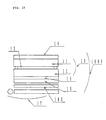
- Figs. 18 and 19 respectively show display devices comprising various coloured films as the coloured layer in accordance with this embodiment.
- any one of the coloured films shown in Figs. 18 and 19 can be used.
- a coloured film which transmits and reflects light at the wavelength of red is used.
- a blackish red display is obtained in the voltage applied portion and a white display is obtained in the voltage unapplied portion, respectively.
- transmissive display with the light from the light source a display having the colour of light emitted from the light source and coloured by the coloured film, i.e., a red display, is obtained in the voltage applied portion, and a black display is obtained in the voltage unapplied portion.
- a dark display is obtained in the voltage unapplied portion and a bright display is obtained in the voltage applied portion, respectively, to obtain a transmissive display, as described above.
- a bright display is obtained in the voltage unapplied portion and a dark display is obtained in the voltage applied portion, respectively.
- the light source When the light source is turned on by using the coloured filter shown in Fig. 8 at incidence of external light, the light emitted from the light source 17 and transmitted through the coloured filter 160 is seen in the voltage applied portion to obtain a greyish red display, and external light reflected by the polarised light separator is seen in the voltage unapplied portion to obtain a grey display, thereby making display significantly easy to see as compared with a black-and-white display.
- coloured filter which reflects or transmits light at the wavelength of red
- Fig. 18 light at the wavelength of a colour other than red may be used.
- a coloured film having a region which reflects or transmits light at the wavelength of red and a region which reflects or transmits light at the wavelength of blue is provided as the coloured layer. These regions are arranged so that emitted light corresponds to each of the character display portions formed in the liquid crystal panel.
- a black display is obtained in the voltage applied portion and a white display is obtained in the voltage unapplied portion, respectively.
- transmissive display with the light from the light source a display having the colour of light emitted from each of the regions of the coloured film, i.e., a red or blue display, is obtained at the corresponding character display portion in the voltage applied portion, and a black display is obtained in the voltage unapplied portion.
- a display having the colour of light emitted from each of the regions of the coloured film i.e., a red or blue display
- a black display is obtained in the voltage unapplied portion.
- coloured film which transmits or reflects light at the wavelength of red and the coloured film which transmits or reflects light at the wavelength of blue are used in Fig. 19, of course, a coloured film which reflects or transmits light at the wavelength of a colour other than these colours may be used, and a combination of coloured films can appropriately be selected.
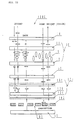
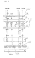
- Fig. 20 is a sectional view of a display device in accordance with a seventh embodiment of the present invention
- Fig. 21 is a schematic sectional view illustrating the principle of display of the display device in accordance with the seventh embodiment of the invention.
- the display device 2000 of this embodiment is a reflective display device with a so-called transflective function, which is capable of not only reflective display using reflection of external light at a place with external light, but also transmissive display using light from a light source at a place without external light.
- a TN liquid crystal panel 10 is used as a variable transmission polarisation axis optical element.
- a TN liquid crystal is held between two glass plates, and a plurality of character display portions 201 and 202 are provided to enable character display.
- On the upper side of the TN liquid crystal panel 10 is provided a polariser 14.
- On the lower side of the TN liquid crystal panel 10 are provided a light scattering member 15, a polarised light separator 16, a light absorber 200 in a grey translucence state, a coloured film 160 as a coloured layer, and a light source 17 in this order.
- a TAB substrate (not shown in the drawing) provided with a driver IC is connected to the TN liquid crystal panel 10 to form the display device.
- polarised light separators having the same function as described above include a separator comprising a cholesteric liquid crystal layer between ⁇ /4 plates, a separator using the Brewster angle (in the manner described in SID 92DIGEST pp. 427-429), a separator using a hologram, and the like. These separators may be used in the display device of this embodiment.
- the external light when external light is incident on the display device 2000, the external light is changed to linearly polarised light parallel to the drawing by the polariser 14, then transmitted through the TN liquid crystal 13 without changing the direction of polarisation, and also transmitted through the polarised light separator 16 without changing the direction of polarisation. Then, the light is absorbed by the light absorber 200 in a grey translucence state to obtain a dark display.
- transmissive display by the light from the light source 17 is described.
- light from the light source 17 is transmitted through the light absorber 160 in a translucence state, is incident on the polarised light separator 16 while being coloured by passing through the coloured film, and is changed to linearly polarised light parallel to the drawing by the polarised light separator 16.
- the linearly polarised light is scattered by the light scattering member 15, then transmitted through the TN liquid crystal 13 without changing the direction of polarisation, and also transmitted through the polariser 14 to obtain a bright display.
- transmissive display with the light from the light source 17 in the voltage unapplied portion, light from the light source 17 is absorbed by the polariser 14 to obtain a dark display, and in the voltage applied portion, light from the light source 17 is transmitted through the polariser 14 to obtain a bright display.
- the display device 2000 of this embodiment is a reflective display device with a so-called transflective function, which is capable of not only bright reflective display using reflection of external light at a place with external light, but also transmissive display using light from the light source 17 at a place without external light.
- the same light absorber as used in the second embodiment i.e., the black light absorber having openings, can also be used as the light absorber 200.
- the area ratio of th openings to the light absorber By limiting the area ratio of th openings to the light absorber, a decrease in contrast can be suppressed as described in the second embodiment.
- a polariser having an absorption axis shifted from that of the polarised light separator 16 can also be used.
- the coloured films described in Figs. 18 and 19 and the sixth embodiment can be used as a coloured layer.
- the operation and advantage of the coloured layer are the same as the sixth embodiment, and thus description thereof is omitted.
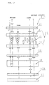
- Fig. 22 is a sectional view of a display device in accordance with an eighth embodiment of the present invention
- Fig. 23 is a schematic sectional view illustrating the principle of display of the display device in accordance with the eighth embodiment of the invention.
- the display device 2200 of this embodiment is a reflective display device with a so-called transflective function, which is capable of not only reflective display using reflection of external light at a place with external light, but also transmissive display using light from a light source at a place without external light.
- a TN liquid crystal panel 10 is used as a variable transmission polarisation axis optical element.
- a TN liquid crystal is held between two glass plates, and a plurality of character display portions 201 and 202 are provided to enable character display.
- a polariser 14 On the upper side of the TN liquid crystal panel 10 is provided a polariser 14.
- a polarised light separator 16 On the lower side of the TN liquid crystal panel 10 are provide a polarised light separator 16, a coloured film 60 as a coloured layer, a reflecting plate having openings, and a light source 17 in this order.
- a TAB substrate (not shown in the drawing) provided with a driver IC is connected to the TN liquid crystal panel 10 to form the display device.
- polarised light separators having the same function as described above include a separator comprising a cholesteric liquid crystal layer between ⁇ /4 plates, a separator using the Brewster angle (in the manner described in SID 92DIGEST pp. 427-429), a separator using a hologram, and the like. These separators may be used in the display device of this embodiment.
- Part of the light emitted from the polarised light separator 16 is transmitted through the coloured layer 160 while being absorbed thereby, reflected by the reflecting plate 220, and again transmitted through the coloured layer 160 while being absorbed thereby. Then the light is again transmitted through the polarised light separator 16, and transmitted as linearly polarised light parallel to the drawing through the TN liquid crystal 13 without changing the direction of polarisation, and emitted as linearly polarised light parallel to the drawing from the polariser 14 to obtain a colour display.
- transmissive display with the light from the light source 17 is described.
- transmissive display with the light from the light source 17 in the voltage unapplied portion, light from the light source 17 is absorbed by the polariser 14 to obtain a dark display, and in the voltage applied portion, light from the light source 17 is transmitted through the polariser 14 to obtain a bright display.
- the display device 2200 of this embodiment is a reflective display device with a so-called transflective function, which is capable of not only a bright reflective display using reflection of external light at a place with external light, but also a transmissive display using light from the light source 17 at a place without external light.
- an A1 reflecting plate or the like can be used as the reflecting plate.
- a half mirror or the like may be used.
- the coloured films described in Figs. 18, 19 and the sixth embodiment can be used as a coloured layer.
- the operation and advantage of the coloured layer are the same as the sixth embodiment, and thus description thereof is omitted.
- Fig. 25(a) is a perspective view of a portable telephone using the display devices described in the first to eighth embodiments of the present invention as a display portion.
- Fig. 25(a) shows a portable telephone
- Fig. 25(b) shows a wristwatch.
- the display device of the present invention can be used for various electronic apparatus such as a personal computer, a car navigation, an electronic handbook, etc.
- the display device of each of the embodiment is capable of half tone display.
- the TN liquid crystal panel 10 is described as an example of variable transmission polarisation axis means, an STN liquid crystal element, an ECB liquid crystal element, and the like can also be used.
- STN liquid crystal element and STN liquid crystal element comprising a colour compensation optical anisotropic material, such as an F-STN liquid crystal element or the like, is preferably used.
- the amount of the light reflected by the light source and returned can be decreased by increasing the distance between the polarised light separator and the light source, whereby a decrease in contrast can be suppressed.
- the quantity of the light which is transmitted through the light absorber and returned by reflection from the light source can be decreased by increasing the distance between the light absorber or the scattering plate and the light source, whereby a decrease in contrast can be suppressed.
- reflection of the surface of the light source can be suppressed by darkening the surface colour of the light source, resulting in a decrease in the quantity of the light which is transmitted through the light absorber and returned by reflection from the light source, whereby a decrease in contrast can be suppressed.
- the bright display with the light reflected by the polarised light separator side is a display with the light reflected by the polarised light separator side, this display is not influenced by the structure of the light absorber disposed behind the polarised light separator.
- the display device described in the first to fifth embodiments may further comprise means for converging light from the light source to the front of the display device.
- the reflective display When a reflective display using external light is seen, the reflective display is generally seen at a position at an angle with the normal to the front of the display device. This is because if the reflective display is seen from the direction normal to the front of the display device, the external light incident on the display device is hindered by the observer, and thus the reflective display by external light is darkened.
- the display using transmitted light from the light source when the display using transmitted light from the light source is seen, the display is generally seen from the direction normal to the front of the display device. Therefore, the display with transmitted light from the light source can be brightened by providing means for converging light from the light source toward to the front of the display device, thereby making the transmissive display by the light from the light source easy to see from the direction normal to the front of the display device.
- a prism sheet is preferably used as means for converging light from the light source toward the front of the display device.
- the prism sheet is preferably provided between the light source and the polarised light separator, and in the sixth to eighth embodiments, the prism sheet is preferably provided between the light source and the coloured film, as shown in Fig. 24.
- the two display states which are the first display state created by the light reflected from the second polarised light separating means, and the second display state where the light transmitted through the second polarised light separating means is absorbed by the optical element, are obtained according to the state of the transmission polarisation axis of the variable transmission polarisation axis means, to form a reflective display device. Since the first display state is a display state created by the light reflected from the second polarised light separating means, a bright display is obtained.
- the two display states which are the third display state created by the light transmitted through the first polarised light separating means, and the fourth display state where no light is transmitted through the first polarised light separating means, are obtained according to the state of the transmission polarisation axis of the variable transmission polarisation axis means, to obtain a transmissive display.
- the display device of the present invention is capable of not only a bright reflective display using reflection of external light at a place with external light, but also a transmissive display using light from the light source at a place without external light.
- the second polarised light separating means is polarised light separating means in which for light over the substantially whole wavelength range of the visible light region, of light incident on the variable transmission polarisation axis means side, a linearly polarised light component in the third predetermined direction is transmitted to the optical element side, and a linearly polarised light component in the fourth predetermined direction perpendicular to the third predetermined direction is reflected to the variable transmission polarisation axis means side, and for light over the substantially whole wavelength range of the visible light region and incident on the optical element side, linearly polarised light in the third predetermined direction can be emitted to the variable transmission polarisation axis means side.
- the first to fourth display states for light over the whole wavelength range of the visible light region can be obtained, and a transmissive or a bright display can be obtained in the first and third display states.
- the optical element mentioned above is an optical element which absorbs light over the substantially whole wavelength range of the visible light region, particularly it is a black light absorber, whereby a dark display can be obtained in the second and fourth display states.
Abstract
Description
- The present invention relates to a display device, and specifically to a display device using a liquid crystal as variable transmission polarisation axis means. Particularly, the present invention relates to a so-called transflective liquid crystal display device functioning as a transmissive liquid crystal display device when a light source is turned on and functioning as a reflective liquid crystal display device when the light source is turned off. Also, the present invention relates to electronic apparatus comprising the display device as a display unit, such as a watch, an electronic handbook, a personal computer, and the like.
- A conventional liquid crystal display device comprising a variable transmission polarisation axis
optical element 2605 in which the polarisation axis of a liquid crystal is variable, such as a TN (Twisted Nematic) liquid crystal, STN (Super-Twisted Nematic) crystal, or the like, has a structure in which the variable transmission polarisation axisoptical element 2605 is sandwiched between twopolarisation 2601 and 2606, as shown in Fig. 26. Therefore, the conventional liquid crystal display device has a low efficiency of light utilisation, and particularly, a reflective type has a problem with dark display. - WO 95/17692 discloses a display device with brightness enhancement including a multiple layer reflective polariser placed between an optical cavity and an LCD module.
- Accordingly, an object of the present invention is to provide a display device using a variable transmission polarisation axis optical element in which the display device is capable of providing a bright display.
- Also, in a conventional transflective liquid crystal display device, a thin reflecting plate is formed, or an opening is provided, thereby decreasing reflectance at reflective display. That is to say, in a transflective type device, brightness of the reflective display is sacrificed.
- Accordingly, another object of the present invention is to provide a transflective liquid crystal display device having a bright reflective display comprising a light source provided on the back of a liquid crystal display device so as to permit not only reflective display by external light but also display by transmitted light from the light source provided on the back of the device.
- In the transflective liquid crystal display device, when external light is incident on the display device with the light source turned on, due to positive-negative reversal, the display is sometimes hard to see.
- Accordingly, a further object of the present invention is to provide a display device in which the display is not hard to see in the case of positive-negative reversal.
- In accordance with the present invention, a display device comprises variable transmission polarisation axis means having a variable transmission polarisation axis, first and second polarised light separating means, disposed on both sides of and sandwiching the variable transmission polarisation axis means, and a light source disposed opposite to the variable transmission polarisation axis means with respect to the second polarised light separating means; wherein the first polarised light separating means is a polarised light separating means in which of light incident on a first side of the first polarised light separating means, a linearly polarised light component in a first predetermined direction is transmitted as linearly polarised light in the first predetermined direction to a second side opposite to the first side; of light incident on the first side of the first polarised light separating means, a linearly polarised light component in a second direction different from the first predetermined direction is not transmitted to the second side; of light incident on the second side of the first polarised light separating means, a linearly polarised light component in the first direction is transmitted as linearly polarised light in the first predetermined direction to the first side; and of light incident on the second side of the first polarised light separating means, a linearly polarised light component in the second direction is not transmitted to the first side; the second polarised light separating means is a polarised light separating means in which of light incident on the variable transmission polarisation axis means side, a linearly polarised light component in a third predetermined direction is transmitted to the light source side, and a linearly polarised light component in a fourth predetermined direction different from the third predetermined direction is reflected to the variable transmission polarisation axis means side; and for light incident from the light source side, linearly polarised light in the third predetermined direction can be emitted to the variable transmission polarisation axis means side.
- In this display device of the present invention, for light incident from the outside of the first polarised light separating means, two display states, i.e., a first display state created by the light reflected from the second polarised light separating means and a second display state where the light transmitted through the second polarised light separating means is absorbed by the light source side, are obtained according to the state of the transmission polarisation axis of the variable transmission polarisation axis means, to operate the display device as a reflective display device. The first display state is a display state created by the light reflected from the second polarised light separating means and thus produces a bright display.
- For light from the light source, two display states, i.e., a third display state created by the light transmitted through the first polarised light separating means, and a fourth display state where no light is transmitted through the first polarised light separating means, are obtained according to the state of the transmission polarisation axis of the variable transmission polarisation axis means, to obtain a transmissive display.
- The second polarised light separating means is preferably a polarised light separating means in which for light over substantially the whole wavelength range of the visible light region, of light incident on the variable transmission polarisation axis means side, a linearly polarised light component in the third predetermined direction is transmitted to the light source side, and a linearly polarised light component in the fourth predetermined direction different from the third predetermined direction is reflected to the variable transmission polarisation axis means side; and for light incident on the light source side which is light over substantially the whole wavelength range of the visible light region, linearly polarised light in the third predetermined direction can be emitted to the variable transmission polarisation axis means side.
- As a result, the first to fourth display states are obtained for light over substantially the whole wavelength range of the visible light region, and a transparent or white display can be obtained in the first and third display states.
- The second polarised light separating means is preferably polarised light separating means in which of light incident on the variable transmission polarisation axis means side, a linearly polarised light component in the third predetermined direction is transmitted as linearly polarised light in the third predetermined direction to the light source side. The second polarised light separating means is preferably polarised light separating means comprising films laminated in a plurality of layers in which the refractive indexes of the plurality of layers are the same between each adjacent layer in the third predetermined direction, and different in the fourth predetermined direction.
- The first polarised light separating means preferably comprises a polariser.
- The variable transmission polarisation axis means preferably comprises a liquid crystal panel, particularly a TN liquid crystal panel, an STN liquid crystal panel, an F-STN liquid crystal panel or an ECB liquid crystal panel. Specifically, the STN liquid crystal panel is an STN liquid crystal panel using a colour compensation optical anisotropic material, such as an F-STN (Film compensated Super-Twisted nematic) liquid crystal panel, or an STN liquid crystal panel positively using the birefringenceof, a liquid crystal without using a colour compensation optical anistropic material.
- Preferably, reflection from the surface of the light source can be suppressed by darkening the surface colour of the light source. Consequently, it is possible to decrease the quantity of the light transmitted through the optical element and returned by reflection from the light source, thereby suppressing a decrease in contrast.
- Preferably, an optical element is further provided between the second polarised light separating means and the light source, which can absorb light from the second polarised light separating means side, and transmits light from the light source to the second polarised light separating means side.
- By providing such an optical element, for light incident from the outside of the first polarised light separating means, it is possible to obtain the two display states, which are the first display state created by the light reflected from the second polarised light separating means and the second display state where the light transmitted through the second polarised light separating means is absorbed by the light source and the optical element in accordance with the state of the transmission polarisation axis of the variable transmission polarisation axis means, and thereby a reflective display can be obtained. In the second display state, light is absorbed by not only the light source but also the optical element, to cause a darker display.
- For light from the light source, the two display states, i.e., the third display state created by the light transmitted through the first polarised light separating means, and the fourth display state where no light is transmitted through the first polarised light separating means, are obtained to realise a transmissive display.
- The optical element is preferably an optical element which absorbs light over substantially the whole wavelength range of the visible region, and more preferably is a black absorber.
- The optical element may have openings. By providing such openings, light from the light source can be transmitted to the second polarised light separating means side through the openings.
- In a reflective display where external light is incident on the display device of the present invention, the two display states, i.e., the first display state created by the light reflected from the second polarised light separating means, and the second display state where light transmitted through the second polarised light separating means is absorbed by the optical element, are obtained, as described above. However, since the optical element is an optical element capable of absorbing light from the second polarised light separating means side and of transmitting light from the light source to the second polarised light separating means side, in the second display state, depending on the structure of the optical elements, light is not completely absorbed by the optical element, with some light transmitted through the optical element, reflected by the light source or the like, and again transmitted through the optical element to return to the variable transmission polarisation axis means side, causing a decrease in contrast.
- Therefore, where the optical element has a plurality of openings, preferably, the quantity of the light transmitted through the optical element and returned through the optical element can be decreased by limiting the ratio of the openings to the optical element, thereby suppressing a decrease in contrast. The area ratio of the openings to the optical element is preferably 5 to 30%.
- Preferably, the quantity of the light transmitted through the optical element and returned by reflection by the liquid source can also be decreased by setting the distance between the optical element and the light source to be larger than the diameter of the openings, thereby suppressing a decrease in contrast.
- The optical element my comprise a light absorber in a grey translucence state so as to permit absorption of light from the second polarised light separating means side, and transmission of light from the light source to the second polarised light separating means side. In this case, the light absorber in a grey translucence state preferably has a transmittance of 10 to 80% to the light over substantially the whole wavelength range of the visible light region. The transmittance is more preferably 10 to 30%.
- The optical element preferably comprises a polariser wherein the transmission axis thereof is deviated from that of the second polarised light separating means. This enables absorption of light from the variable transmission polarisation axis means side and transmission of light from the light source to the variable transmission polarisation axis means side.
- The optical element preferably comprises a light scattering member capable of changing the polarisation state of light incident on the optical element and of emitting light therefrom. By providing such an optical element, for light incident from the outside of the first polarised light separating means, the two display states, i.e., the first display state created by the light reflected by the second polarised light separating means, and the second display state where light transmitted through the second polarised light separating means cannot be transmitted through a polarised light separator due to removal of the polarisation state by scattering a plate, are obtained according to the state of the transmission polarisation axis of the variable transmission polarisation axis means, and therefore a reflective display device can be formed. In the second display state, light is not only absorbed by the light source but also scattered by the optical element to obtain a darker display.
- For light from the light source, the two display states, i.e., the third display state created by the light transmitted through the first polarised light separating means, and the fourth display state where no light is transmitted through the first polarised light separating means, are obtained in accordance with the state of the transmission polarisation axis of the variable transmission polarisation axis means, to obtain a transmissive display.
- Preferably, means for converging light from the light source to the front of the display device is further provided.
- When seeing the reflective display provided by external light, the display is generally seen at a position which is at an angle with the normal to the front of the display device. This is because if the display is seen from the direction normal to the front of the display device, external light incident on the display device is hindered by the observer, and thus the reflective display becomes dark. On the other hand, when seeing the display obtained by transmitted light from the light source, the display is generally seen from the direction normal to the front of the display device, and thus the display obtained by transmitted light from the light source can be bright by providing means for converging light from the light source to the front of the display device. As a result, a transmissive display obtained by the light from the light source can easily be seen in the direction normal to the front of the display device.
- Preferably, a light diffusion means is further provided. This can bring about a white display in the first display state by reflection of external light from the second polarised light separating means and the third display state by transmission of light from the light source through the first polarised light separating means.
- The light source may comprise a cold cathode tube capable of emitting white light, and a light guide plate capable of emitting white light incident from the cold cathode tube to the second polarised light separating means side. In the use of white light, for light from the light source, the two display states, which are the third display state created by the light transmitted through the first polarised light separating means and the fourth display state where no light is transmitted through the first polarised light separating means, can be obtained to form transmissive display, as described above. However, for example, a white display is obtained in the third display state when the state of the transmission polarisation axis of the variable transmission polarisation axis means is on, and a black display is obtained in the fourth display state when the state of the transmission polarisation axis of the variable transmission polarisation axis means is off, in accordance with the structure of the display device. In this case, when external light is incident on the first polarised light separating means side of the display device, the external light produces a black display in the second display state with the transmission polarisation axis of the variable transmission polarisation axis means turned on, and produces a white display in the first display state with the transmission polarisation axis of the variable transmission polarisation axis means turned off.
- As a result, in both the on and off states, for example, when the display obtained by transmitted light from the light source is a white display, a grey display is obtained due to addition of a reflective black display by external light, and when the display obtained by transmitted light from the light source is a black display, grey is also obtained due to addition of a reflective white display by external light, thereby causing positive-negative reversal and making the display hard to see.
- Therefore, an LED capable of emitting light in the predetermined wavelength region to the second polarised light separating means side, or an EL element capable of emitting light in the predetermined wavelength region is preferably used for colouring light from the light source, thereby obtaining a colour display on a grey background and making it easy to see a display obtained by the light from the light source.
- Where an LED is used as the light source, the light source preferably comprises a first LED capable of emitting light in a first predetermined wavelength range, and a second LED capable of emitting light in a second predetermined wavelength range different from the first predetermined wavelength range. Where an EL element is used as the light source, the light source preferably comprises a first EL element capable of emitting light in a third predetermined wavelength range, and a second EL element capable of emitting light in a fourth predetermined wavelength range different from the third predetermined wavelength range. Preferably, the first and second LED or the first and second EL elements correspond to respective character display portions to obtain different display colours in the respective character display portions, thereby usefully widening the selection range of design possibilities.
- Where an LED is used as the light source, the light source preferably comprises an LED capable of emitting light in a predetermined wavelength region, and a light guide plate capable of emitting light in the predetermined wavelength region to the second polarised light separating means side. In this way, since, after light emitted from the LED is incident on the light guide plate, the light can be emitted to the second polarised light separating means side, the arrangement position of the LED can be relatively freely determined, thereby widening the range of design possibilities and making the light uniform for emitting to the second polarised light separating means side.
- The light guide plate preferably has a first light guide region where light in a first predetermined wavelength range is incident from the first LED and emitted to the second polarised light separating means side, and a second light guide region where light in a second predetermined wavelength range is incident from the second LED and emitted to the second polarised light separating means side, with light shielding means polarised between the first light guide region and the second light guide region. By providing such light shielding means, mixing of the first predetermined wavelength region and the second predetermined wavelength region is prevented, and thus colour purity is increased.
- A coloured layer capable of transmitted or reflecting light in a predetermined wavelength region, and of absorbing light at wavelengths out of the predetermined wavelength region may be provided between the light source and the second polarised light separating means. This causes light from the light source to be coloured and incident on the second polarised light separating means, and a colour display on a grey background is thus obtained, thereby making it easy to see the transmissive display with the light from the light source. In this case, since light from the light source is coloured, a white light source such as a cold cathode tube may be used as the light source. Of course, the above-described LED or EL element may be used.
- The coloured layer preferably has a first coloured region capable of reflecting or transmitting light in a first predetermined wavelength range, and a second coloured region capable of transmitting or reflecting light in a second predetermined range different from the first predetermined wavelength range, and is able to absorb light at wavelengths out of the first or second predetermined wavelength range. Preferably, the first and second coloured regions correspond to respective character display portions to obtain different display colours in the respective character display portions, thereby widening the range of selection of design possibilities.
- More preferably, a transflective plate which can transmit light from the light source to the coloured layer side, reflect light which is incident on the coloured layer from the second polarised light separating means side and is transmitted through the coloured layer, and emit the light to the coloured layer side, is further provided. As the transflective plate, a mirror reflecting plate having openings provided therein can be used. In this configuration, for light incident from the outside of the first polarised light separating means, the two display states, which are the first display state created by the light reflected by the second polarised light separating means, and the second display state created by the light transmitted through the second polarised light separating means and reflected by the coloured layer, and light transmitted through the coloured layer and then reflected by the reflecting plate, are obtained according to the state of the transmission polarisation axis of the variable transmission axis means, to form a reflective display device. In the second display state, the purity of colour is increased due to the presence of the reflecting plate.
- An electronic apparatus of the present invention comprises the above display device as a display unit.
- Embodiments of the present invention will now be described by way of further example only and with reference to the accompanying drawings, in which:-
- Fig. 1 is a sectional view of a display device in accordance with a first embodiment of the present invention.
- Fig. 2 is a schematic sectional view illustrating the principle of display of the display device in accordance with the first embodiment of the present invention.
- Fig. 3 is a schematic drawing of the configuration of a polarised
light separator 16 used in an embodiment of the present invention. - Fig. 4 is a drawing illustrating the operation of the polarised
light separator 16 shown in Fig. 3. - Fig. 5 is a drawing illustrating an example of a light source used in the present invention.
- Fig. 6 is a drawing illustrating another example of a light source used in the present invention.
- Fig. 7 is a drawing illustrating still another example of a light source used in the present invention.
- Fig. 8 is a drawing illustrating a further example of a light source used in the present invention.
- Fig. 9 is a drawing illustrating a still further example of a light source used in the present invention.
- Fig. 10 is a sectional view of a display device in accordance with a second embodiment of the present invention.
- Fig. 11 is a schematic sectional view illustrating the principle of display of the display device in accordance with the second embodiment of the present invention.
- Fig. 12 is a schematic sectional view illustrating a display device in accordance with a third embodiment of the present invention.
- Fig. 13 is a schematic sectional view illustrating a display device in accordance with a fourth embodiment of the present invention.
- Fig. 14 is a sectional view of a display device in accordance with a fifth embodiment of the present invention.
- Fig. 15 is a schematic view illustrating the principle of display of the display device in accordance with the fifth embodiment of the present invention.
- Fig. 16 is a sectional view of a display device in accordance with a sixth embodiment of the present invention.
- Fig. 17 is a schematic sectional view illustrating the principle of display of the display device in accordance with the sixth embodiment of the present invention.
- Fig. 18 is a drawing illustrating an example of a coloured layer used in the present invention.
- Fig. 19 is a drawing illustrating another example of a coloured layer used in the present invention.
- Fig. 20 is a sectional view of a display device in accordance with a seventh embodiment of the present invention.
- Fig. 21 is a schematic sectional view illustrating the principle of display of the display device in accordance with the seventh embodiment of the present invention.
- Fig. 22 is a sectional view of the display device in accordance with an eighth embodiment of the present invention.
- Fig. 23 is a schematic sectional view illustrating the principle of display of the display device in accordance with the eighth embodiment of the present invention.
- Fig. 24 is a drawing showing an example in which a prism sheet is combined with a display device of the present invention.
- Fig. 25 is drawing showing examples of electronic apparatus comprising a display device as a display unit.
- Fig. 26 is a drawing showing an example of a conventional display device.
-
- Fig. 1 is a sectional view of a display device in accordance with a first embodiment of the present invention, and Fig. 2 is a schematic sectional view illustrating the principle of display of the display device in accordance with the first embodiment of the present invention.
- A
display 100 of this embodiment is a display device with a so-called transflective function which is capable of not only reflective display using reflection of external light in a place where external light is present, but also transmission display using light from a light source in a place where external light is absent. - First the structure of the display device of this embodiment is described with reference to Fig. 1. In the
display device 100, a TNliquid crystal panel 10 is used as a variable transmission polarisation axis optical element. In the TNliquid crystal panel 10, a TNliquid crystal 13 is held between twoglass plates liquid crystal panel 10 is provided apolariser 14. On the lower side of the TNliquid crystal panel 10 are provided alight scattering member 15, a polarisedlight separator 16, and alight source 17 in this order. In order to drive the TNliquid crystal 10, a TAB substrate (not shown in the drawing) provided with a driver IC is connected to the TNliquid crystal panel 10 to form the display device. - Next, the polarised light separator used in this embodiment is described with reference to Figs. 3 and 4. Fig. 4 is a schematic drawing showing the configuration of the polarised
light separator 16 used in this embodiment, and is a drawing illustrating the operation of the polarisedlight separator 16 shown in Fig. 3. The polarisedlight separator 16 has a structure in which two layers 41 (A layer) and 42 (B layer) are alternately laminated in a plurality of layers. In the polarisedlight separator 16, although the refractive index (nAX) of the A layers 41 in the X axis direction is different from the refractive index (nBX) of the B layers 42 in the X axis direction, the refractive index (nAX) of the A layers 41 in the Y axis direction is substantially the same as the refractive index (nBY) of the B layers 42 in the Y axis direction. Of light incident on the polarisedlight separator 16, linearly polarised light in the Y axis direction is transmitted through the polarisedlight separator 16 because the refractive index of the A layers 41 is substantially the same as the reflective index of the B layers in the polarisedlight separator 16. On the other hand, in the polarisedlight separator 16, if the thickness of the A layers 41 in the Z axis direction is tA, and the thickness of the B layers 41 is tB, the following equation is satisfied:light separator 16, linearly polarised light in the X axis direction is reflected by the polarisedlight separator 16. Since the thickness of the A layers 41 and the thickness of the B layers 42 in the Z axis direction varies, of light incident on the polarisedlight separator 16 over a wide range of the visible wavelength region, the polarisedlight separator 16 reflects linearly polarised light in the X axis direction. - In the polarised
light separator 16, oriented polyethylene napthalate (PET; polyethylene naphthalate ) is used for the A layers 41, and copolyester of naphthalene dicarboxylic acid and terephthalic acid (coOEN; copolyester of napthalene dicarboxylic acid and terephthalic or isothalic acid) can be used for the B layers 42. - Of course, materials of the polarised
light separator 16 used in the present invention are not limited to these materials, and materials can be appropriately selected. Such a polarised light separator is disclosed in detail as a reflective polariser in Unexamined International Patent Applications (International Application No. WO/95/27819 and WO95/17692). - Although, in this embodiment, the above polarised light separator is used, besides the polarised light separator, a separator comprising a cholesteric liquid crystal layer held between λ/4 plates, a separator using the angle of polarisation (in the manner described in SID 92DIGEST pp. 427-429), a separator using hologram, and the like have the same function as the above polarised light separator, and may be used for the display device of this embodiment.
- On the assumption that the right half of the
display device 100 is a voltage applied portion, and the left half thereof is a voltage unapplied portion, the principle of display with thedisplay device 100 is described below with reference to Fig. 2. - First a reflective display where external light is incident on the
display device 100 is described. - In the voltage unapplied portion on the left hand side, when external light is incident on the
display device 100, the external light is changed to linearly polarised light parallel to the plane of the drawing (hereinafter the plane of the drawing will simply be referred to as "the drawing") by thepolariser 14, and then the direction of polarisation is rotated 90° by the TNliquid crystal 13 to form linearly polarised light perpendicular to the drawing. The linearly polarised light perpendicular to the drawing is reflected by the polarisedlight separator 16, and then the direction of polarisation is rotated 90° by the then TNliquid crystal 13 to form linearly polarised light parallel to the drawing, which is emitted as linearly polarised light parallel to the drawing from thepolariser 14. With no voltage applied, incident external light is reflected by the polarisedlight separator 16, not absorbed thereby, to obtain a bright reflective display. Since thelight scattering member 15 is provided between the polarisedlight separator 16 and the TNliquid crystal panel 10, light reflected from the polarisedlight separator 16 is changed from a mirror state to a white state. - In the voltage applied portion on the right hand side, when external light is incident on the
display device 100, the external light is changed to linearly polarised light parallel to the drawing, and then transmitted through the TNliquid crystal 13 without change in the direction of polarisation, and the polarisedlight separator 16 is also transmitted without change in the direction of polarisation to reach thelight source 17. Since most of the light which reaches thelight source 17 is transmitted through the light source or absorbed thereby, the display becomes dark. - In this way, in a reflective display where external light is incident on the
display device 100, in the voltage unapplied portion, light reflected by the polarisedlight separator 16 is transmitted through thelight scattering member 15 to make the display bright, and in the voltage applied portion, light transmitted through the polarisedlight separator 16 is mostly transmitted through or absorbed by thelight source 17 to make the display dark. - With no voltage applied, since external light incident on the
display device 100 is reflected by the polarisedseparator 16, not absorbed thereby, a bright display is obtained. - Next, a transmissive display with the light from the light source is described.
- In the voltage unapplied portion on the left hand side, light from the
light source 17 is incident on the polarisedlight separator 16, and changed to linearly polarised light parallel to the drawing by the polarisedlight separator 16. Then the direction of polarisation is rotated 90° by the TNliquid crystal 13 to form linearly polarised light perpendicular to the drawing, which is absorbed by thepolariser 14, to make the display dark. - In the voltage applied portion on the right hand side, light from the
light source 17 is incident on the polarisedlight separator 16, scattered by thelight scattering member 15, then transmitted through the TNliquid crystal 13 without change in the direction of polarisation, and also transmitted through thepolariser 14, to make the display bright. - In this way, in a transmissive display with the light from the
light source 17, in the voltage unapplied portion, light from thelight source 17 is absorbed by thepolariser 14 to make the display dark. In the voltage applied portion, light from the light source is transmitted through thepolariser 14 to make the display bright. - Therefore, the
display device 100 of this embodiment is a reflective display device with a so-called transflective function, which is capable of not only reflective display using reflection of external light at a place with external light, but also transmissive display using light from thelight source 17 at a place without external light. - As the scattering plate used in the display device of this embodiment, a scattering plate capable of emitting incident light without removing the state of polarisation to the utmost. Since this scattering plate has the function to scatter and cloud the light emitted from the scattering plate, a display device with a cloudy display (white display) is obtained. In contrast, removal of the
scattering plate 15 from the configuration produces a display device with a glossy display. Therefore, the scattering plate may be selected in accordance with application of the display device. - Figs. 5 to 9 respectively show display devices using various light sources in accordance with this embodiment of the present invention. In this embodiment, any one of the light sources shown in Figs. 5 to 8 can be used.
- The light source used in the display device shown in Fig. 5 comprises a
cold cathode tube 50 as a light source and a light guide plate 51. As the light guide plate 51, a light guide plate having the function to absorb light when thecold cathode tube 50 is turned off is used. Where the light source shown in Fig. 5 is used for the display device of this embodiment, the display where external light including visible wavelength components having a plurality of colours is incident, i.e., a reflective display, becomes a black display in the voltage applied portion and becomes a white display in the voltage unapplied portion, respectively. On the other hand, a transmissive display with the light from the light source becomes a display having the colour of the light emitted from the cold cathode tube, i.e., a white display, in the voltage applied portion, and becomes a black display in the voltage unapplied portion. - The light source used for the display device shown in Fig. 6 comprises an LED 60 which emits light at the wavelength corresponding to red as light source, and a light guide plate 61. In use of the light source shown in Fig. 6 for the display device of this embodiment, a reflective display becomes a black display in the voltage applied portion and becomes a white display in the voltage unapplied portions, respectively. On the other hand, a transmissive display using light from the light source becomes a display having the colour of the light emitted from the LED 60, i.e., a red display, in the voltage applied portion, and becomes a black display in the voltage unapplied portion.
- In use of the light source shown in Fig. 5, as described above, for light from the
light source 17, a dark display is obtained in the voltage unapplied portion and a bright display is obtained in the voltage applied portion, respectively, to form a transmissive display. However, in this case, when external light is incident on the front side of the display device, a bright display is obtained in the voltage unapplied portion and a dark display is obtained in the voltage applied portion, respectively, due to the external light. As a result, in both the voltage unapplied portion and the voltage applied portion, for example, when a display with transmitted light from thelight source 17 is a bright display, a grey display is obtained due to addition of a reflective dark display by external light, and when a display with transmitted light from thelight source 17 is a dark display, a grey display is obtained due to the addition of a reflective bright display by external light, to cause so-called positive-negative reversal and sometimes make the display hard to see. - When the light source shown in Fig. 6 is turned on at incidence of external light, in the voltage applied portion, the light emitted from the LED can be seen so as to make the display greyish red, and in the voltage unapplied portion, the light reflected by the polarised
light separator 16 can be seen so as to make the display grey. Therefore, the display is significantly easy to see as compared with a simple black-and-white display. - The LED 60 which emits light having the wavelength corresponding to red is used in Fig. 6, but an LED which emits light having the wavelength corresponding to a colour other than red may be used.
- The light source used for the display device shown in Fig. 7 comprises an
EL element 70 as a light source, which emits light having the wavelength of green. In use of the light source shown in Fig. 7 for the display device of this embodiment, a reflective display becomes a black display in the voltage applied portion and becomes a white display in the voltage unapplied portion, respectively. On the other hand, a transmissive display by the light from the light source becomes a display having the colour of the light emitted from theEL element 70, i.e., a green display, in the voltage applied portion, and becomes a black display in the voltage unapplied portion. When the light source shown in Fig. 7 is turned on at incidence of external light, in the voltage applied portion, the light emitted from theEL element 70 can be seen so as to make the display greyish green, and in the voltage unapplied portion, the external light reflected by the polarised light separator can be seen so as to make the display grey. TheEL element 70 which emits light having the wavelength of green is used in Fig. 7, but, of course, an EL element which emits light having the wavelength of a colour other than green may be used. - The light source used for the display device shown in Fig. 8 comprises as light sources an LED 81 which emits light having the wavelength of red, and an LED 82 which emits light having the wavelength of blue, both LEDs being disposed on the side of a
light guide plate 83. The light guide plate is partitioned by a reflectingplate 84 into regions corresponding to the LEDs so as to not to mix light having the wavelengths emitted from the respective light guide plates. The LEDs are arranged so that the emitted lights correspond to a plurality ofcharacter display portions 85 and 86 formed in the liquid crystal panel. In use of the light source shown in Fig. 8 for the display device of this embodiment, a reflective display becomes a black display in the voltage applied portion and becomes a white display in the voltage unapplied portion, respectively. On the other hand, a transmissive display with the light from the light source becomes a display having the colour of the light emitted from each of the LEDs in the corresponding character display portion, i.e., a red or blue display, in the voltage applied portion, and becomes a black display in the voltage unapplied portion. When thelight source 8 shown in Fig. 8 is turned on at incidence of external light, in the voltage applied portion, the light emitted from each of the LEDs can be seen to make the display greyish red or blue in each of the character display portions, and in the voltage unapplied portion, external light reflected by the polarised light separator can be seen to make the display grey. As shown in Fig. 8, the LED which emits light having the wavelength of red and the LED which emits light having the wavelength of blue are used, but, of course, an LED which emits light having the wavelength of a colour other than these colours may be used, and combinations may be appropriately selected according to application. - The light source used for the display device shown in Fig. 9 comprises a plurality of LEDs 91 which emit light having the wavelength of red, and a plurality of LEDs 92 which emit light having the wavelength of blue, with the LEDs arranged as a group for each of the colours. The light source shown in Fig. 9 has no light guide plate. Further, the LED groups are arranged so that the emitted lights respectively correspond to a plurality of character display portions formed in the liquid crystal panel. In use of the light source shown in Fig. 9 for the display device of this embodiment, a reflective display becomes a black display in the voltage applied portion and becomes a white display in the voltage unapplied portion, respectively. On the other hand, a transmissive display by the light from the light source becomes a display having the colour of the light emitted from each of the LED groups respectively corresponding to the character display portions, i.e., a red or blue display, in the voltage applied portion, and becomes a black display in the voltage unapplied portion. When the light source shown in Fig. 9 is turned on at incidence of external light, light emitted from each of the LED groups can be seen to make the display greyish red or blue in each of the character display portions in the voltage applied portion, and external light reflected by the polarised light separator can be seen to make the display grey in the voltage unapplied portion. The LED 91 which emits light having the red wavelength and the LED 92 which emits light having the blue wavelength are used in Fig. 9, but, of course, LEDs which emits light having the wavelength of a colour other than these colours may be used, and the combination can be appropriately selected.
- Fig. 10 is a sectional view of a display device in accordance with a second embodiment of the present invention, and Fig. 11 is a schematic sectional view illustrating the principle of display of the display device in the second embodiment of the invention.
- The display device 1000 of this embodiment is a reflective display device with a so-called transflective function, which is capable of not only reflective display using reflection of external light at a place with external light, but also transmissive display using light from the light source at a place without external light.
- First, the structure of the display device of this embodiment is described with reference to Fig. 10. In the display device 1000, a TN
liquid crystal panel 10 is used as a variable transmission polarisation axis optical element. In the TNliquid crystal panel 10, a TNliquid crystal 13 is held between twoglass plates liquid crystal panel 10 is provided apolariser 14. On the lower side of the TNliquid crystal panel 10 are provided alight scattering member 15, a polarisedlight separator 101, alight absorber 102, and alight source 17 in this order. Thelight absorber 102 is black and has a plurality ofopenings 103 at a predetermined area density. In order to drive the TNliquid crystal 13, a TAB substrate (not shown in the drawing) provided with a driver IC is connected to the TNliquid crystal panel 10 to form the display device. - The polarised
light separator 101 comprises a (1/4)λ plate 104 and a cholestericliquid crystal layer 105. The cholestericliquid crystal layer 105 is illuminated with light having the same wavelength as the pitch of the liquid crystal and reflects circularly polarised light with the same direction of rotation as the liquid crystal, transmitting other light. Therefore, for example, when a cholesteric liquid crystal having a pitch of 5000 angstroms and counterclockwise rotation is used for the cholestericliquid crystal layer 105, a device is obtained in which left-handed circularly polarised light having a wavelength of 5000 angstroms is reflected, and right-handed circularly polarised light and light having other wavelengths are transmitted. Further, by using a cholesteric liquid crystal having counterclockwise rotation and changing the pitch thereof in the cholesteric liquid crystal over the whole wavelength range of visible light, an element is obtained which reflects left-handed circularly polarised light not only for monochrome light but also over the whole range of bright colour light, and transmits right-handed circularly polarised light. In this embodiment, a cholesteric liquid crystal having counterclockwise rotation is used for the cholestericliquid crystal layer 105, and the pitch thereof is changed in the cholesteric liquid crystal over the whole wavelength range of visible light. - In the polarised
light separator 101 comprising the combination of the cholestericliquid crystal layer 105 and the (1/4)λ plate 104, when linearly polarised light in a predetermined first direction is incident on the (1/4)λ plate 104 side, the light is changed to left-handed circularly polarised light by the (1/4)λ plate 104, reflected by the cholestericliquid crystal layer 105, changed again to linearly polarised light in the predetermined first direction by the (1/4)λ plate 104, and then emitted. When linearly polarised light in a second direction perpendicular to the first direction is incident, the light is changed to right-handed circularly polarised light by the (1/4)λ plate 104, and transmitted through the cholestericliquid crystal layer 105. For light incident on the lower side of the cholestericliquid crystal layer 105, linearly polarised light in the second direction is emitted upward from the (1/4)λ plate 104. - In this way, the polarised
light separator 101 comprising the combination of the cholestericliquid crystal layer 105 and the (1/4)λ plate 104 is a polarised light separating means in which of light incident from the (1/4)λ plate 104 side, a linearly polarised light component in the predetermined second direction is transmitted, and a linearly polarised light component in the first direction perpendicular to the predetermined second direction is reflected, and for light incident on the cholestericliquid crystal layer 105 side, linearly polarised light in the second direction can be emitted to the (1/4)λ plate 104 side. Besides the polarisedlight separator 101 comprising the combination of the cholestericliquid crystal layer 105 and the (1/4)λ plate 104, polarised light separators having the above function include a separator comprising films laminated in multilayers (of the type disclosed in USP 4,974,219), a separator for separating into reflective polarised light and transmissive polarised light using Brewster angle ( in the manner described in SID 92DIGEST pp. 427-429), a separator using a hologram, and the polarised light separator described above in the first embodiment with reference to Figs. 3 and 4, i.e., the separator disclosed in Unexamined International Patent Applications (International Application Nos. WO95/27819 and WO95/17692). - On the assumption that the right half of the display device 1000 is a voltage applied portion, and the left half thereof is a voltage unapplied portion, the principle of display by the display device 1000 is described.
- First, a reflective display where external light is incident on the display device 1000 is described.
- In the voltage unapplied portion on the left hand side, when external light is incident on the display device 1000, the external light is changed to linearly polarised light parallel to the drawing by the
polariser 14, and then the direction of polarisation is rotated 90° by the TNliquid crystal 13 to form linearly polarised light perpendicular to the drawing. The linearly polarised light perpendicular to the drawing is changed to left-handed circularly polarised light by the (1/4)λ plate 104, reflected by the cholestericliquid crystal layer 105, is again incident on the (1/4)λ plate 104, and changed to linearly polarised light perpendicular to the drawing by the (1/4)λ plate 104. Then the direction of polarisation is rotated 90° by the TNliquid crystal 13 to form linearly polarised light parallel to the drawing, which is emitted as linearly polarised light parallel to the drawing from thepolariser 14. In this way, with no voltage applied, since incident external light is reflected by the polarisedlight separator 101, not absorbed thereby, a bright reflective display can be obtained. Since thelight scattering member 15 is provided between the polarisedlight separator 101 and the TNliquid crystal panel 10, light reflected by the polarisedlight separator 101 is changed from a mirror state to a bright colour state. - In the voltage applied portion on the right hand side, when external light is incident on the display device 1000, the external light is changed to linearly polarised light parallel to the drawing by the
polariser 14, and then transmitted through the TNliquid crystal 13 without changing the direction of polarisation. The linearly polarised light is changed to right-handed circularly polarised light by the (1/4)λ plate 104, and transmitted through the cholestericliquid crystal layer 105. The right-handed circularly polarised light transmitted through the cholestericliquid crystal layer 105 is absorbed by theblack light absorber 102 to obtain a dark display. - In this way, in a reflective display where external light is incident on the
display device 100, in the voltage unapplied portion, light reflected by the polarisedlight separator 101 is transmitted through thelight scattering member 15 to obtain a bright display, and in the voltage applied portion, light transmitted through the polarisedlight separator 101 is absorbed by thelight absorber 102 to obtain a dark display. - With no voltage applied, since external light incident on the display device 1000 is reflected by the polarised
separator 101, not absorbed thereby, a bright display is obtained. - Next, a transmissive display by the light from the
light source 17 is described. - In the voltage unapplied portion on the left hand side, light from the
light source 17 is incident on the cholestericliquid crystal layer 105 of the polarisedlight separator 101 through theopenings 103 provided in theblack light absorber 102, and only right-handed circularly polarised light is transmitted through the cholestericliquid crystal layer 105, and changed to linearly polarised light parallel to the drawing by the (1/4)λ plate 104. Then the direction of polarisation is rotated 90° by the TNliquid crystal 13 to form linearly polarised light perpendicular to the drawing, which is absorbed by thepolariser 14 to obtain a dark display. - In the voltage applied portion on the right hand side, light from the
light source 17 is incident on the polarisedlight separator 101 and on the cholestericliquid crystal layer 105 through theopenings 103 provided in theblack light absorber 102, and only right-handed circularly polarised light is transmitted through the cholestericliquid crystal layer 105 and changed to linearly polarised light parallel to the drawing by the (1/4)λ plate 104. The linearly polarised light is transmitted through thelight scattering member 15, through the TNliquid crystal 13 without changing the direction of polarisation, and then through thepolariser 14 to obtain a bright display. - In this way, in a transmissive display by the light from the
light source 17, in the voltage unapplied portion, light from thelight source 17 is absorbed by thepolariser 14 to obtain a dark display, and in the voltage applied portion, light from thelight source 17 is transmitted through thepolariser 14 to obtain a bright display. - Therefore, the display device 1000 of this embodiment is a reflective display device with a so-called transflective function, which is capable of not only a bright reflective display using reflection of external light at a place with external light, but also a transmissive display using light from the
light source 17 at a place with external light. - As the
scattering plate 15 used in the display device of this embodiment, a scattering plate capable of emitting incident light without removing the state of polarisation to the utmost is used. Since this scattering plate has the function to scatter and cloud the light emitted from the scattering plate, a display device with a cloudy display (white display) is obtained. In contrast, removal of thescattering plate 15 from the configuration produces a display device with a glossy display. Therefore, the scattering plate may be selected in accordance with application of the display device. - In this embodiment, in a reflective display where external light is incident on the display device 1000, the two display states, i.e., a bright display by the light reflected by the polarised
light separator 101, and a dark display where light transmitted through the polarisedlight separator 101 is absorbed by thelight absorber 102, are obtained, as described above. However, since thelight absorber 102 is a black light absorber to absorb light from the polarisedlight separator 101, and has a plurality of theopenings 103 through which light can be transmitted, in the dark display state, light is not completely absorbed by thelight absorber 102, but some light is transmitted through theopenings 103 of thelight absorber 102, reflected by the light source or the like, again transmitted through theopenings 103 of thelight absorber 102, and returned to the TNliquid crystal panel 10 side, causing a decrease in contrast. - Therefore, the area ratio of the
openings 103 to thelight absorber 102 is preferably limited to decrease the amount of the light which is transmitted through theopenings 103 of thelight absorber 102, reflected by thelight source 17 or the like, and returned through theopenings 103 of thelight absorber 102, thereby suppressing a decrease in contrast. - Although, in this embodiment, a black light absorber having the plurality of
openings 103 is used as thelight absorber 102, a light absorber in a grey translucence state can also be used for absorbing light from the polarisedlight separator 101 side and for transmitting light from the light source to the polarisedlight separator 101 side. In this case, since the light absorber is in a grey translucence state, the openings need not be provided. As the light absorber in a grey translucence state, light diffusion film D202 (produced by Tsujimoto Denki Seisakusho) or the like can be used. - Although the black light absorber having the plurality of
openings 103 is used as thelight absorber 102, a polariser having an absorption axis shifted from that of the polarisedlight separator 101 can be used in place of thelight absorber 102. In this way, with the polarisedlight separator 101 and the polariser having an absorption axis shifted from that of the polarisedlight separator 101, light from the TNliquid crystal panel 10 side can be absorbed and light from thelight source 17 can be transmitted to the TNliquid crystal panel 10 side. - In the display device of this embodiment, the various light sources shown in Figs. 1 to 9 and described in the first embodiment can be used. The operation and advantages are the same as the first embodiment, and thus description thereof is omitted.
- Fig. 12 is a schematic sectional view illustrating a display device in accordance with a third embodiment of the invention.
- In the second embodiment, the polarised
light separator 101 comprising the (1/4)λ plate 104 and the cholestericliquid crystal layer 105 is used. This embodiment is different from the second embodiment in that a polarised light separator 121 comprising a (1/4)λ plate 104, a cholestericliquid crystal layer 105, and a (1/4) λ plate 120 is used in place of the polarisedlight separator 101, but other points are the same as the second embodiment. - In the polarised light separator 121 comprising the (1/4)
λ plates 104 and 120 on both sides of the cholestericliquid crystal layer 105, when linearly polarised light in a predetermined first direction is incident on the (1/4)λ plate 104 side, the light is changed to left-handed circularly polarised light by the (1/4)λ plate 104, reflected by the cholestericliquid crystal layer 105, changed again to linearly polarised light in the predetermined first direction by the (1/4)λ plate 104, and then emitted. When linearly polarised light in a second direction perpendicular to the first direction is incident, the light is changed to right-handed circularly polarised light by the (1/4)λ plate 104, transmitted through the cholestericliquid crystal layer 105, again changed to linearly polarised light in the second direction by the (1/4) λ plate 120, and then emitted. For light incident on the lower side of the (1/4) λ plate 146, linearly polarised light in the second direction is emitted upward from the (1/4)λ plate 104. - In this way, the polarised light separator 121 comprising a combination of the cholesteric
liquid crystal layer 105 and the (1/4)λ plates 104 and 120 is polarised light separating means in which of light incident on the (1/4)λ plate 104 side, a linearly polarised light component in the predetermined second direction is transmitted, and a linearly polarised light component in the first direction perpendicular to the predetermined second direction is reflected, and for light incident on the (1/4) λ plate 120 side, linearly polarised light in the second direction can be emitted to the (1/4)λ plate 104 side. Alternative arrangements for the polarised light separator 121, rather than the combination of the cholestericliquid crystal layer 105 and the (1/4)λ plates 104 and 120, include: a separator comprising multilayer laminated films (of the type disclosed in USP 4,974,219); a separator for separating reflected polarised light and transmitted polarised light by using the Brewster angle (in the manner disclosed in SID 92DIGEST pp. 427-429); a separator using a hologram; and the polarised light separator described above in the first embodiment with reference to Figs. 3 and 4, i.e., the separator disclosed as a reflective polariser in Unexamined International Patent Applications (International Application Nos. WO95/27819 and WO95/17692). - On the assumption that the right half of the
display device 1200 is a voltage applied portion, and the left half thereof is a voltage unapplied portion, the principle of display by thedisplay device 1200 is described below. - First, a reflective display where external light is incident on the
display device 1200 is described. - The function of the voltage unapplied portion on the left hand side is the same as the voltage unapplied portion of the first embodiment. Namely, when external light is incident on the
display device 1200, the external light is changed to linearly polarised light parallel to the drawing by thepolariser 14, and then the direction of polarisation is rotated 90° by the TNliquid crystal 13 to form linearly polarised light perpendicular to the drawing. The linearly polarised light perpendicular to the drawing is changed to left-handed circularly polarised light by the (1/4)λ plate 104, reflected by the cholestericliquid crystal layer 105 to be incident again on the (1/4)λ plate 104, and changed to linearly polarised light perpendicular to the drawing by the (1/4)λ plate 104. Then the direction of polarisation is rotated 90° by the TNliquid crystal 13 to form linearly polarised light parallel to the drawing, which is emitted as linearly polarised light parallel to the drawing from thepolariser 14. In this way, with no voltage applied, incident external light is reflected by the polarised light separator 121, not absorbed thereby, to obtain a bright reflective display. Since thelight scattering member 15 is provided between the (1/4)λ plate 104 and the TNliquid crystal panel 10, light reflected by the polarisedlight separator 101 is changed from a mirror state to a white state. - In the voltage applied portion on the right hand side, when external light is incident on the
display device 1200, the external light is changed to linearly polarised light parallel to the drawing by thepolariser 14, and then transmitted through the TNliquid crystal 13 without changing the direction of polarisation. The linearly polarised light is changed to right-handed circularly polarised light by the (1/4)λ plate 104, and transmitted through the cholestericliquid crystal layer 105. The right-handed circularly polarised light transmitted through the cholestericliquid crystal layer 105 is changed to linearly polarised light parallel to the drawing by the (1/4) λ plate 120, and then absorbed by theblack light absorber 102 to obtain a dark display. - In this way, in a reflective display where external light is incident on the
display device 1200, in the voltage unapplied portion, light is reflected by the polarised light separator 121 to obtain a bright display, and in the voltage applied portion, light transmitted through the polarised light separator 121 is absorbed by thelight absorber 102 to obtain a dark display. - With no voltage applied, since external light incident on the
display device 1200 is reflected by the polarised separator 121, not absorbed thereby, a bright display is obtained. - Next, transmissive display with the light from the
light source 17 is described. - In the voltage unapplied portion on the left hand side, light from the
light source 17 is incident on the (1/4) λ plate 120 of the polarised light separator 121 through theopenings 103 provided in theblack light absorber 102, transmitted through the (1/4) λ plate 120 to be incident on the cholestericliquid crystal layer 105, in which right-handed circularly polarised light is transmitted, and left-handed circularly polarised light is reflected. The transmitted circularly polarised light is changed to linearly polarised light parallel to the drawing by the (1/4)λ plate 104. Then the direction of polarisation is rotated 90° by the TNliquid crystal 13 to form linearly polarised light perpendicular to the drawing, which is absorbed by thepolariser 14 to obtain a dark display. - In the voltage applied portion on the right hand side, light from the
light source 17 is incident on the (1/4) λ plate 120 of the polarised light separator 121 through theopenings 103 provided in theblack light absorber 102, and only right-handed circularly polarised light of the light incident on the cholestericliquid crystal layer 105 is transmitted therethrough and changed to linearly polarised light parallel to the drawing by the (1/4)λ plate 104. The linearly polarised light is transmitted through thelight scattering member 15, through the TNliquid crystal 13 without changing the direction of polarisation, and then through thepolariser 14 to obtain a bright display. - In this way, in transmissive display with the light from the
light source 17, in the voltage unapplied portion, light from thelight source 17 is absorbed by thepolariser 14 to obtain a dark display, and in the voltage applied portion, light from thelight source 17 is transmitted through thepolariser 14 to obtain a bright display. - Therefore, the
display device 1200 of this embodiment is a reflective display device with a so-called transflective function, which is capable of not only bright reflective display using reflection of external light at a place with external light, but also transmissive display using light from thelight source 17 at a place without external light. - As the scattering plate used in the display device of this embodiment, a scattering plate capable of emitting incident light without removing the state of polarisation to the utmost is used. Since this scattering plate has the function to scatter and cloud the light emitted from the scattering plate, a display device with a cloudy display (white display) is obtained. In contrast, removal of the
scattering plate 15 from the configuration produces a display device with a glossy display. Therefore, the scattering plate should be selected in accordance with application of the display device. - The same light absorber as that used in the second embodiment can be used in this embodiment. By limiting the area ratio of the
openings 103 to thelight absorber 102, a decrease in contrast can be suppressed as described in the second embodiment. Of course, like in the second embodiment, a light absorber in a grey translucence state and a polariser having an absorption axis shifted from that of the polarised light separator 121 can also be used. - In the display device of this embodiment, the various light sources described in Figs. 1 to 9 and the first embodiment can be used. The operation and advantages are the same as the first embodiment, and thus description thereof is omitted.
- Fig. 13 is a schematic sectional view illustrating a display device according to a fourth embodiment of the invention.
- The polarised
light separator 101 comprising the (1/4)λ plate 104 and the cholestericliquid crystal layer 105 is used in the second embodiment, and the polarised light separator 121 comprising the (1/4)λ plate 104, the cholestericliquid crystal layer 105 and the (1/4) λ plate 120 is used in the third embodiment. This embodiment is different from the second and third embodiments in that the polarised light separator described above in the first embodiment with reference to Figs. 3 and 4, i.e., the separator disclosed as a reflective polariser in Unexamined International Applications (International Application Nos. WO95/27819 and WO95/17692) is used as the polarisedlight separator 16 instead of the polarisedlight separator - In this embodiment, the same as described above in the first embodiment with reference to Figs. 3 and 4 is used. Detailed description of the polarised light separator is omitted. Of course, besides this polarised light separator, polarised light separators having the same function as described above include a separator comprising a cholesteric liquid crystal layer between λ/4 plates, a separator using the Brewster angle (in the manner described in SID 92DIGEST pp. 427-429), a separator using a hologram, and the like. These separators may be used in the display device of this embodiment.
- On the assumption that the right half of the
display device 1300 is a voltage applied portion, and the left half thereof is a voltage unapplied portion, the principle of display by thedisplay device 1300 is described. - First, reflective display where external light is incident on the
display device 1300 is described. - In the voltage unapplied portion on the left hand side, when external light is incident on the
display device 1300, the external light is changed to linearly polarised light parallel to the drawing by thepolariser 14. And then the direction of polarisation is rotated 90° by the TNliquid crystal 13 to form linearly polarised light perpendicular to the drawing, which is reflected by the polarisedlight separator 16, maintaining a state of the linearly polarised light perpendicular to the drawing. The direction of polarisation is rotated 90° by the TNliquid crystal 13 to form linearly polarised light parallel to the drawing, which is emitted as linearly polarised light parallel to the drawing from thepolariser 14. In this way, with no voltage applied, incident external light is reflected by the polarisedlight separator 16, not absorbed thereby, to obtain a bright reflective display. Since thelight scattering member 15 is provided between the polarisedlight separator 16 and the TNliquid crystal panel 10, light reflected by the polarisedlight separator 101 is changed from a mirror state to a bright colour state. - In the voltage applied portion on the right hand side, when external light is incident on the
display device 1300, the external light is changed to linearly polarised light parallel to the drawing by thepolariser 14, then transmitted through the TNliquid crystal 13 without changing the direction of polarisation, then also transmitted through the polarisedlight separator 16 without changing the direction of polarisation, and then absorbed by theblack light absorber 102 to obtain dark display. - In this way, in a reflective display where external light is incident on the
display device 1300, the voltage unapplied portion, light reflected by the polarisedlight separator 16 is transmitted through thelight scattering member 15 to obtain a bright display, and in the voltage applied portion, light transmitted through the polarisedlight separator 16 is absorbed by thelight absorber 102 to obtain a dark display. - With no voltage applied, since external light incident on the
display device 1300 is reflected by the polarisedseparator 16, not absorbed thereby, a bright display is obtained. - Next, transmissive display with the light from the
light source 17 is described. - In the voltage unapplied portion on the left hand side, light from the
light source 17 is incident on the polarisedlight separator 16 through theopenings 103 provided in theblack light absorber 102, and changed to linearly polarised light parallel to the drawing by the polarisedlight separator 16. Then the direction of polarisation is rotated 90° by the TNliquid crystal 13 to form linearly polarised light perpendicular to the drawing, which is absorbed by thepolariser 14 to obtain dark display. - In the voltage applied portion on the right hand side, light from the
light source 17 is incident on the polarisedlight separator 16 through theopenings 103 provided in theblack light absorber 102, and changed to linearly polarised light parallel to the drawing by the polarisedlight separator 16. The linearly polarised light is scattered by thelight scattering member 15, then transmitted through the TNliquid crystal 13 without changing the direction of polarisation, and also transmitted through thepolariser 14 to obtain a bright display. - In this way, in transmissive display by the light from the
light source 17, in the voltage unapplied portion, light from thelight source 17 is absorbed by thepolariser 14 to obtain a dark display, and in the voltage applied portion, light from thelight source 17 is transmitted through thepolariser 14 to obtain a bright display. - Therefore, the
display device 1300 of this embodiment is a reflective display device with a so-called transflective function, which is capable of not only bright reflective display using reflection of external light at a place with external light, but also transmissive display using light from thelight source 17 at a place without external light. - As the scattering plate used in the display device of this embodiment, a scattering plate capable of emitting incident light without removing the state of polarisation to the utmost is used. Since this scattering plate has the function to scatter and cloud the light emitted from the scattering plate, a display device with a cloudy display (white display) is obtained. In contrast, removal of the
scattering plate 15 from the configuration produces a display device with a glossy display. Therefore, the scattering plate should be selected in accordance with application of the display device. - The same light absorber as that used in the second embodiment can be used in this embodiment. By limiting the area ratio of the
openings 103 to thelight absorber 102, a decrease in contrast can be suppressed as described in the second embodiment. Of course, like in the second embodiment, a light absorber in a grey translucence state and a polariser having an absorption axis shifted from that of the polarisedlight separator 101 or 121 can also be used. - In the display device of this embodiment, the various light sources described in Figs. 1 to 9 and the first embodiment can be used. The operation and advantages are the same as the first embodiment, and thus description thereof is omitted.
- Fig. 14 is a sectional view of a display device in the fifth embodiment of the present invention, and Fig. 15 is a schematic sectional view illustrating the principle of display of the display device in the fifth embodiment of the invention.
- The
display device 100 of this embodiment is a reflective display device with a so-called transflective function, which is capable of not only reflective display using reflection of external light at a place with external light, but also transmissive display using light from a light source at a place without external light. - The structure of the display device of this embodiment is described with reference to Fig. 14. In the
display device 1400 of this embodiment, a TNliquid crystal panel 10 is used as a variable transmission polarisation axis optical element. In the TNliquid crystal panel 10, a TNliquid crystal 13 is held between twoglass plates liquid crystal panel 10 is provided apolariser 14. On the lower side of the TNliquid crystal panel 10 are provided alight scattering member 15, a polarisedlight separator 16, adiffusion plate 140, and alight source 17 in this order. As thediffusion plate 140, a diffusion plate capable of changing the state of polarisation of incident light is used. A TAB substrate (not shown in the drawing) provided with a driver IC for driving the TNliquid crystal 13 is connected to the TNliquid crystal panel 10 to form the display device. - In this embodiment, the same separator as described above in the first embodiment with reference to Figs. 3 and 4 is used. Detailed description of the polarised light separator is therefore omitted. Of course, besides this polarised light separator, polarised light separators having the same function as described above include a separator comprising a cholesteric liquid crystal layer between λ/4 plates, a separator using the Brewster angle (in the manner described in SID 92DIGEST pp. 427-429), a separator using a hologram, and the like. These separators may be used in the display device of this embodiment.
- On the assumption that the right half of the
display device 1400 is a voltage applied portion, and the left half thereof is a voltage unapplied portion, the principle of display by thedisplay device 1400 is described with reference to Fig. 15. - First, reflective display where external light is incident on the
display device 1400 is described. - In the voltage unapplied portion on the left hand side, when external light is incident on the
display device 1400, the external light is changed to linearly polarised light parallel to the drawing by thepolariser 14. And then the direction of polarisation is rotated 90° by the TNliquid crystal 13 to form linearly polarised light perpendicular to the drawing, which is reflected by the polarisedlight separator 16, maintaining the state of linearly polarised light perpendicular to the drawing. And the direction of polarisation is rotated 90° by the TNliquid crystal 13 to form linearly polarised light parallel to the drawing, which is emitted as linearly polarised light parallel to the drawing from thepolariser 14. In this way, with no voltage applied, incident external light is reflected by the polarisedlight separator 16, not absorbed thereby, to obtain a bright reflective display. Since thelight scattering member 15 is provided between the polarisedlight separator 16 and the TNliquid crystal panel 10, light reflected by the polarisedlight separator 101 is changed from a mirror state to a white state. - In the voltage applied portion on the right hand side, when external light is incident on the
display device 1400, the external light is changed to linearly polarised light parallel to the drawing by thepolariser 14, then transmitted through the TNliquid crystal 13 without changing the direction of polarisation, also transmitted through the polarisedlight separator 16 without changing the direction of polarisation, and then scattered by thescattering plate 140, changing the state of polarisation. Most of the light scattered to the polarised light separator side by thescattering plate 140 cannot be transmitted through the polarised light separator because the state of polarisation is removed, resulting in a dark display. - In this way, in reflective display where external light is incident on the
display device 1300, in the voltage unapplied portion, light reflected by the polarisedlight separator 16 is transmitted through thelight scattering member 15 to obtain a bright display, and in the voltage applied portion, light transmitted through the polarisedlight separator 16 is scattered by thescattering plate 140 with a change in the state of polarisation to obtain a dark display. - With no voltage applied, since external light incident on the
display device 1300 is reflected by the polarisedseparator 16, not absorbed thereby, a bright display is obtained. - Next, transmissive display by the light from the
light source 17 is described. - In the voltage unapplied portion on the left hand side, light from the
light source 17 is incident on the polarisedlight separator 16 through thescattering plate 140, and changed to linearly polarised light parallel to the drawing by the polarisedlight separator 16. Then the direction of polarisation is rotated by 90° by the TNliquid crystal 13 to form linearly polarised light perpendicular to the drawing, which is absorbed by thepolariser 14 to obtain a dark display. - In the voltage applied portion on the right hand side, light from the
light source 17 is incident on the polarisedlight separator 16 through thescattering plate 140, and changed to linearly polarised light parallel to the drawing by the polarisedlight separator 16. The linearly polarised light is scattered by thelight scattering member 15, then transmitted through the TNliquid crystal 13 without changing the direction of polarisation, and also transmitted through thepolariser 14 to obtain a bright display. - In this way, in transmissive display with the light from the
light source 17, in the voltage unapplied portion, light from thelight source 17 is absorbed by thepolariser 14 to obtain a dark display, and in the voltage applied portion, light from thelight source 17 is transmitted through thepolariser 14 to obtain a bright display. - Therefore, the
display device 1400 of this embodiment is a reflective display device with a so-called transflective function, which is capable of not only bright reflective display using reflection of external light at a place with external light, but also transmissive display using light from thelight source 17 at a place without external light. - As the scattering plate used in the display device of this embodiment, a scattering plate capable of emitting incident light without removing the state of polarisation to the utmost is used. Since this scattering plate has the function to scatter and cloud the light emitted from the scattering place, a display device with a cloudy display (white display) is obtained. In contrast, removal of the
scattering plate 15 from the configuration produces a display device with a glossy display. Therefore, the scattering plate should be selected in accordance with application of the display device. - In the display device of this embodiment, the various light sources described in Figs. 1 to 9 and the first embodiment can be used. The operation and advantages are the same as the first embodiment, and thus description thereof is omitted.
- Fig. 16 is a sectional view of a display device in accordance with a sixth embodiment of the present invention, and Fig. 17 is a schematic sectional view illustrating the principle of display of the display device in accordance with the sixth embodiment of the invention.
- The
display device 1600 of this embodiment is a reflective display device with a so-called transflective function, which is capable of not only reflective display using reflection of external light at a place with external light, but also transmissive display using light from a light source at a place without external light. - The structure of the display device of this embodiment is described with reference to Fig. 16. In the
display device 1600 of this embodiment, a TNliquid crystal panel 10 is used as a variable transmission polarisation axis optical element. In the TNliquid crystal panel 10, a TNliquid crystal 13 is held between twoglass plates liquid crystal panel 10 is provided apolariser 14. On the lower side of the TNliquid crystal panel 10 are provided alight scattering member 15, a polarisedlight separator 16, acoloured film 160 as a coloured layer, and a light source 60 in this order. As the coloured film, a translucence film capable of changing the state of polarisation of light at a predetermined wavelength to emit the light, and absorbing light at wavelengths other than the above wavelength is used. As the light source, a cold cathode tube which is a white light source is used. In order to drive the TNliquid crystal 13, a TAB substrate (not shown in the drawing) provided with a drive IC is connected to the TNliquid crystal panel 10 to form the display device. - In this embodiment, the same polarised light separator as described above in the first embodiment with reference to Fig. 3 and 4 is used. Detailed description of the polarised light separator is therefore omitted. Of course, besides this polarised light separator, polarised light separators having the same function as described above include a separator comprising a cholesteric liquid crystal layer between λ/4 plates, a separator using the Brewster angle (in the manner described in SID 92DIGEST pp. 427-429), a separator using a hologram, and the like. These separators may be used in the display device of this embodiment.
- On the assumption that the right half of the
display device 1600 is a voltage applied portion, and the left half thereof is a voltage unapplied portion, the principle of display by thedisplay device 1600 is described with reference to Fig. 17. - First, reflective display where external light is incident on the
display device 1600 is described. - In the voltage unapplied portion on the left hand side, when external light is incident on the
display device 1600, the external light is changed to linearly polarised light parallel to the drawing by thepolariser 14. And then the direction of polarisation is rotated 90° by the TNliquid crystal 13 to form linearly polarised light perpendicular to the drawing, which is reflected by the polarisedlight separator 16, remaining the state of the linearly polarised light perpendicular to the drawing. The direction of polarisation is rotated 90° by the TNliquid crystal 13 to form linearly polarised light parallel to the drawing, which is emitted as linearly polarised light parallel to the drawing from thepolariser 14. In this way, with no voltage applied, incident light is reflected by the polarisedlight separator 16, not absorbed thereby, to obtain a bright reflective display. Since thelight scattering member 15 is provided between the polarisedlight separator 16 and the TNliquid crystal panel 10, light reflected by the polarisedlight separator 101 is changed from a mirror state to a white state. - In the voltage applied portion on the right hand side, when external light is incident on the
display device 1600, the external light is changed to linearly polarised light parallel to the drawing by thepolariser 14, then transmitted through the TNliquid crystal 13 without changing the direction of polarisation, and also transmitted through the polarisedlight separator 16 without changing the direction of polarisation. Then, light in a predetermined wavelength range is absorbed by thecoloured film 160. Since light in the predetermined wavelength range is absorbed by thecoloured film 160, a dark display is obtained. - In this way, in reflective display where external light is incident on the
display device 1600, in the voltage unapplied portion, light reflected by the polarisedlight separator 16 is transmitted through thelight scattering member 15 to obtain a bright display, and in the voltage applied portion, light transmitted through the polarisedlight separator 16 is absorbed by thecoloured film 50 to obtain a dark display. - With no voltage applied, since external light incident on the
display device 1600 is reflected by the polarisedseparator 16, not absorbed thereby, a bright display is obtained. - Next, transmissive display with the light from the
light source 17 is described. - In the voltage unapplied portion on the left hand side, light from the
light source 17 is incident on the polarisedlight separator 16 through thecoloured film 160, and changed to linearly polarised light parallel to the drawing by the polarisedlight separator 16. Then the direction of polarisation is rotated 90° by the TNliquid crystal 13 to form linearly polarised light perpendicular to the drawing, which is absorbed by thepolariser 14 to obtain a dark display. - In the voltage applied portion on the right hand side, light from the
light source 17 is incident on the polarisedlight separator 16 while being coloured by passing through thecoloured film 160, and changed to linearly polarised light parallel to the drawing by the polarisedlight separator 16. The linearly polarised light is scattered by thelight scattering member 15, then transmitted through the TNliquid crystal 13 without changing the direction of polarisation, and also transmitted through thepolariser 14 to obtain a bright display. - In this way, in transmissive display with the light from the
light source 17, in the voltage unapplied portion, light from thelight source 17 is absorbed by thepolariser 14 to obtain a dark display, and in the voltage applied portion, light from thelight source 17 is transmitted through thepolariser 14 to obtain a bright display. - Therefore, the
display device 1600 of this embodiment is a reflective display device with a so-called transflective function, which is capable of not only bright reflective display using reflection of external light at a place with external light, but also transmissive display using light from thelight source 17 at a place without external light. - As the scattering plate used in the display device of this embodiment, a scattering plate capable of emitting incident light without removing the state of polarisation to the utmost is used. Since this scattering plate has the function to scatter and cloud the light emitted from the scattering plate, a display device with a cloudy display (white display) is obtained. In contrast, removal of the
scattering plate 15 from the configuration produces a display device with a glossy display. Therefore, the scattering plate should be selected in accordance with application of the display device. - Figs. 18 and 19 respectively show display devices comprising various coloured films as the coloured layer in accordance with this embodiment. In this embodiment, any one of the coloured films shown in Figs. 18 and 19 can be used.
- In the display device shown in Fig. 18, a coloured film which transmits and reflects light at the wavelength of red is used. In the display device shown in Fig. 18, as for reflective display, a blackish red display is obtained in the voltage applied portion and a white display is obtained in the voltage unapplied portion, respectively. On the other hand, as for transmissive display with the light from the light source, a display having the colour of light emitted from the light source and coloured by the coloured film, i.e., a red display, is obtained in the voltage applied portion, and a black display is obtained in the voltage unapplied portion.
- Where the coloured film is not used, but a light source emitting white light is used, for the light from the
light source 17, a dark display is obtained in the voltage unapplied portion and a bright display is obtained in the voltage applied portion, respectively, to obtain a transmissive display, as described above. In this case, when external light is incident on the front side of the display device, due to the external light, a bright display is obtained in the voltage unapplied portion and a dark display is obtained in the voltage applied portion, respectively. As a result, in both the voltage unapplied portion and the voltage applied portion, for example, when display by transmitted light from thelight source 17 is a bright display, a grey display is obtained due to addition of a reflective dark display by external light, and when display by transmitted light from thelight source 17 is a dark display, a grey display is obtained due to addition of a reflective bright display by external light. Therefore, so-called positive-negative reversal occurs, and sometimes makes the display hard to see. - When the light source is turned on by using the coloured filter shown in Fig. 8 at incidence of external light, the light emitted from the
light source 17 and transmitted through thecoloured filter 160 is seen in the voltage applied portion to obtain a greyish red display, and external light reflected by the polarised light separator is seen in the voltage unapplied portion to obtain a grey display, thereby making display significantly easy to see as compared with a black-and-white display. - Although the coloured filter which reflects or transmits light at the wavelength of red is used in Fig. 18, of course, light at the wavelength of a colour other than red may be used.
- In the display device shown in Fig. 19, a coloured film having a region which reflects or transmits light at the wavelength of red and a region which reflects or transmits light at the wavelength of blue is provided as the coloured layer. These regions are arranged so that emitted light corresponds to each of the character display portions formed in the liquid crystal panel. When using the coloured film shown in Fig. 19 in the display device of this embodiment, in reflective display, a black display is obtained in the voltage applied portion and a white display is obtained in the voltage unapplied portion, respectively. On the other hand, as for transmissive display with the light from the light source, a display having the colour of light emitted from each of the regions of the coloured film, i.e., a red or blue display, is obtained at the corresponding character display portion in the voltage applied portion, and a black display is obtained in the voltage unapplied portion. When the light source shown in Fig. 19 is turned on at incidence of external light, the light emitted from each of the LED groups is seen, causing a greyish red or blue display at each of the character display portions in the voltage applied portion, and external light reflected by the polarised light separator is seen, causing a grey display in the voltage unapplied portion. Although the coloured film which transmits or reflects light at the wavelength of red and the coloured film which transmits or reflects light at the wavelength of blue are used in Fig. 19, of course, a coloured film which reflects or transmits light at the wavelength of a colour other than these colours may be used, and a combination of coloured films can appropriately be selected.
- Fig. 20 is a sectional view of a display device in accordance with a seventh embodiment of the present invention, and Fig. 21 is a schematic sectional view illustrating the principle of display of the display device in accordance with the seventh embodiment of the invention.
- The
display device 2000 of this embodiment is a reflective display device with a so-called transflective function, which is capable of not only reflective display using reflection of external light at a place with external light, but also transmissive display using light from a light source at a place without external light. - The structure of the display device of this embodiment is described with reference to Fig. 20. In the
display device 2000 of this embodiment, a TNliquid crystal panel 10 is used as a variable transmission polarisation axis optical element. In the TNliquid crystal panel 10, a TN liquid crystal is held between two glass plates, and a plurality ofcharacter display portions liquid crystal panel 10 is provided apolariser 14. On the lower side of the TNliquid crystal panel 10 are provided alight scattering member 15, a polarisedlight separator 16, alight absorber 200 in a grey translucence state, acoloured film 160 as a coloured layer, and alight source 17 in this order. In order to drive the TNliquid crystal 13, a TAB substrate (not shown in the drawing) provided with a driver IC is connected to the TNliquid crystal panel 10 to form the display device. - In this embodiment, the same polarised light separator as described above in the first embodiment with reference to Figs. 3 and 4 is used. Detailed description of the polarised light separator is therefore omitted. Of course besides this polarised light separator, polarised light separators having the same function as described above include a separator comprising a cholesteric liquid crystal layer between λ/4 plates, a separator using the Brewster angle (in the manner described in SID 92DIGEST pp. 427-429), a separator using a hologram, and the like. These separators may be used in the display device of this embodiment.
- On the assumption that the right half of the
display device 2000 is a voltage applied portion, and the left half thereof is a voltage unapplied portion, the principle of display by thedisplay device 2000 is described with reference to Fig. 21. - First, reflective display where external light is incident on the
display device 2000 is described. - In the voltage unapplied portion on the left hand side, when external light is incident on the
display device 2000, the external light is changed to linearly polarised light parallel to the drawing by thepolariser 14. Then the direction of polarisation is rotated 90° by the TNliquid crystal 13 to form linearly polarised light perpendicular to the drawing, which is reflected by the polarisedlight separator 16, remaining the state of the linearly polarised light perpendicular to the drawing. And the direction of polarisation is rotated 90° by the TNliquid crystal 13 to form linearly polarised light parallel to the drawing, which is emitted as linearly polarised light parallel to the drawing from thepolariser 14. In this way, with no voltage applied, incident external light is reflected by the polarisedlight separator 16, not absorbed thereby, to obtain a bright reflective display. Since thelight scattering member 15 is provided between the polarisedlight separator 16 and the TNliquid crystal panel 10, light reflected by the polarisedlight separator 101 is changed from a mirror state to a white state. - In the voltage applied portion on the right hand side, when external light is incident on the
display device 2000, the external light is changed to linearly polarised light parallel to the drawing by thepolariser 14, then transmitted through the TNliquid crystal 13 without changing the direction of polarisation, and also transmitted through the polarisedlight separator 16 without changing the direction of polarisation. Then, the light is absorbed by thelight absorber 200 in a grey translucence state to obtain a dark display. - In this way, in reflective display where external light is incident on the
display device 1600, in the voltage unapplied portion, light reflected by the polarisedlight separator 16 is transmitted through thelight scattering member 15 to obtain a bright display, and in the voltage applied portion, light transmitted through the polarisedlight separator 16 is absorbed by thelight absorber 200 in a grey translucence state to obtain a dark display. - With no voltage applied, since external light incident on the
display device 1600 is reflected by the polarisedseparator 16, not absorbed thereby, a bright display is obtained. - Next, transmissive display by the light from the
light source 17 is described. - In the voltage unapplied portion on the left hand side, light from the
light source 17 passes through thelight absorber 160 in a translucence state, passes through the coloured film while being coloured, and is incident on the polarisedlight separator 16. The light is changed to linearly polarised light parallel to the drawing by the polarisedlight separator 16. Then the direction of polarisation is rotated 90° by the TNliquid crystal 13 to form linearly polarised light perpendicular to the drawing, which is absorbed by thepolariser 14 to obtain dark display. - In the voltage applied portion on the right hand side, light from the
light source 17 is transmitted through thelight absorber 160 in a translucence state, is incident on the polarisedlight separator 16 while being coloured by passing through the coloured film, and is changed to linearly polarised light parallel to the drawing by the polarisedlight separator 16. The linearly polarised light is scattered by thelight scattering member 15, then transmitted through the TNliquid crystal 13 without changing the direction of polarisation, and also transmitted through thepolariser 14 to obtain a bright display. - In this way, in transmissive display with the light from the
light source 17, in the voltage unapplied portion, light from thelight source 17 is absorbed by thepolariser 14 to obtain a dark display, and in the voltage applied portion, light from thelight source 17 is transmitted through thepolariser 14 to obtain a bright display. - Therefore, the
display device 2000 of this embodiment is a reflective display device with a so-called transflective function, which is capable of not only bright reflective display using reflection of external light at a place with external light, but also transmissive display using light from thelight source 17 at a place without external light. - In this embodiment, besides the light absorber in a translucence state, the same light absorber as used in the second embodiment, i.e., the black light absorber having openings, can also be used as the
light absorber 200. By limiting the area ratio of th openings to the light absorber, a decrease in contrast can be suppressed as described in the second embodiment. Of course, like in the second embodiment, a polariser having an absorption axis shifted from that of the polarisedlight separator 16 can also be used. - In the display device of this embodiment, the coloured films described in Figs. 18 and 19 and the sixth embodiment can be used as a coloured layer. The operation and advantage of the coloured layer are the same as the sixth embodiment, and thus description thereof is omitted.
- Fig. 22 is a sectional view of a display device in accordance with an eighth embodiment of the present invention, and Fig. 23 is a schematic sectional view illustrating the principle of display of the display device in accordance with the eighth embodiment of the invention.
- The
display device 2200 of this embodiment is a reflective display device with a so-called transflective function, which is capable of not only reflective display using reflection of external light at a place with external light, but also transmissive display using light from a light source at a place without external light. - The structure of the display device of this embodiment is described with reference to Fig. 22. In the
display device 2200 of this embodiment, a TNliquid crystal panel 10 is used as a variable transmission polarisation axis optical element. In the TNliquid crystal panel 10, a TN liquid crystal is held between two glass plates, and a plurality ofcharacter display portions liquid crystal panel 10 is provided apolariser 14. On the lower side of the TNliquid crystal panel 10 are provide a polarisedlight separator 16, a coloured film 60 as a coloured layer, a reflecting plate having openings, and alight source 17 in this order. In the reflectingplate 220 are provided a plurality ofopenings 221 at a predetermined area ratio. In order to drive the TNliquid crystal 13, a TAB substrate (not shown in the drawing) provided with a driver IC is connected to the TNliquid crystal panel 10 to form the display device. - In this embodiment, the same polarised light separator as described above in the first embodiment with reference to Figs. 3 and 4 is used. Detailed description of the polarised light separator is therefore omitted. Of course, besides this polarised light separator, polarised light separators having the same function as described above include a separator comprising a cholesteric liquid crystal layer between λ/4 plates, a separator using the Brewster angle (in the manner described in SID 92DIGEST pp. 427-429), a separator using a hologram, and the like. These separators may be used in the display device of this embodiment.
- On the assumption that the right half of the
display device 2200 is a voltage applied portion, and the left half thereof is a voltage unapplied portion, the principle of display by thedisplay device 2200 is described with reference to Fig. 23. - First, reflective display where external light is incident on the
display device 2200 is described. - In the voltage unapplied portion on the left hand side, when external light is incident on the
display device 2200, the external light is changed to linearly polarised light parallel to the drawing by thepolariser 14. And then the direction of polarisation is rotated 90° by the TNliquid crystal 13 to form linearly polarised light perpendicular to the drawing, which is reflected by the polarisedlight separator 16, remaining in the state of the linearly polarised light perpendicular to the drawing. And the direction of polarisation is rotated 90° by the TNliquid crystal 13 to form linearly polarised light parallel to the drawing, which is emitted as linearly polarised light parallel to the drawing from thepolariser 14. In this way, with no voltage applied, incident external light is reflected by the polarisedlight separator 16, not absorbed thereby, to obtain a bright reflective display. - In the voltage applied portion on the right hand side, when external light is incident on the
display device 2000, the external light is changed to linearly polarised light parallel to the drawing by thepolariser 14, then transmitted through the TNliquid crystal 13 without changing the direction of polarisation, and also transmitted through the polarisedlight separator 16 without changing the direction of polarisation. Part of the light is reflected by thecoloured layer 160, again transmitted through the polarisedlight separator 160, transmitted as linearly polarised light parallel to the drawing through the TNliquid crystal 140, and emitted as linearly polarised light parallel to the drawing from thepolariser 14. Part of the light emitted from the polarisedlight separator 16 is transmitted through thecoloured layer 160 while being absorbed thereby, reflected by the reflectingplate 220, and again transmitted through thecoloured layer 160 while being absorbed thereby. Then the light is again transmitted through the polarisedlight separator 16, and transmitted as linearly polarised light parallel to the drawing through the TNliquid crystal 13 without changing the direction of polarisation, and emitted as linearly polarised light parallel to the drawing from thepolariser 14 to obtain a colour display. - Next, transmissive display with the light from the
light source 17 is described. - In the voltage unapplied portion on the left hand side, light from the
light source 17 is incident on the polarisedlight separator 16 while being coloured by the coloured film through theopenings 221 provided in the reflectingplate 220. The light is changed to linearly polarised light parallel to the drawing by the polarisedlight separator 16. Then the direction of polarisation is rotated 90° by the TNliquid crystal 13 to form linearly polarised light perpendicular to the drawing, which is absorbed by thepolariser 14 to obtain a dark display. - In the voltage applied portion on the right hand side, light from the
light source 17 passes through theopenings 221 provided in the reflectingplate 220, is incident on the polarisedlight separator 16 while being coloured by passing through thecoloured layer 160, and changed to linearly polarised light parallel to the drawing by the polarisedlight separator 16. The linearly polarised light is transmitted through the TNliquid crystal 13 without changing the direction of polarisation, and also transmitted through thepolariser 14 to obtain a bright display. - In this way, in transmissive display with the light from the
light source 17, in the voltage unapplied portion, light from thelight source 17 is absorbed by thepolariser 14 to obtain a dark display, and in the voltage applied portion, light from thelight source 17 is transmitted through thepolariser 14 to obtain a bright display. - Therefore, the
display device 2200 of this embodiment is a reflective display device with a so-called transflective function, which is capable of not only a bright reflective display using reflection of external light at a place with external light, but also a transmissive display using light from thelight source 17 at a place without external light. - In this embodiment, an A1 reflecting plate or the like can be used as the reflecting plate. Besides the reflecting plate having the openings, a half mirror or the like may be used.
- In the display device of this embodiment, the coloured films described in Figs. 18, 19 and the sixth embodiment can be used as a coloured layer. The operation and advantage of the coloured layer are the same as the sixth embodiment, and thus description thereof is omitted.
- Fig. 25(a) is a perspective view of a portable telephone using the display devices described in the first to eighth embodiments of the present invention as a display portion. Fig. 25(a) shows a portable telephone, and Fig. 25(b) shows a wristwatch.
- Although, in this embodiment, a portable telephone and a wristwatch are shown, the display device of the present invention can be used for various electronic apparatus such as a personal computer, a car navigation, an electronic handbook, etc.
- Although, in the first to ninth embodiment, only dark display, bright display and colour display are described, of course, the display device of each of the embodiment is capable of half tone display.
- Also, although, in the first to ninth embodiments, the TN
liquid crystal panel 10 is described as an example of variable transmission polarisation axis means, an STN liquid crystal element, an ECB liquid crystal element, and the like can also be used. As the STN liquid crystal element, and STN liquid crystal element comprising a colour compensation optical anisotropic material, such as an F-STN liquid crystal element or the like, is preferably used. - In the first to ninth embodiments, preferably, the amount of the light reflected by the light source and returned can be decreased by increasing the distance between the polarised light separator and the light source, whereby a decrease in contrast can be suppressed.
- Also, in the second to fifth embodiments, and the seventh and eighth embodiments, the quantity of the light which is transmitted through the light absorber and returned by reflection from the light source can be decreased by increasing the distance between the light absorber or the scattering plate and the light source, whereby a decrease in contrast can be suppressed.
- Also, in the first to eighth embodiments, reflection of the surface of the light source can be suppressed by darkening the surface colour of the light source, resulting in a decrease in the quantity of the light which is transmitted through the light absorber and returned by reflection from the light source, whereby a decrease in contrast can be suppressed.
- In the second to fifth embodiment, and the seventh embodiment, since the bright display with the light reflected by the polarised light separator side is a display with the light reflected by the polarised light separator side, this display is not influenced by the structure of the light absorber disposed behind the polarised light separator.
- The display device described in the first to fifth embodiments may further comprise means for converging light from the light source to the front of the display device.
- When a reflective display using external light is seen, the reflective display is generally seen at a position at an angle with the normal to the front of the display device. This is because if the reflective display is seen from the direction normal to the front of the display device, the external light incident on the display device is hindered by the observer, and thus the reflective display by external light is darkened. On the other hand, when the display using transmitted light from the light source is seen, the display is generally seen from the direction normal to the front of the display device. Therefore, the display with transmitted light from the light source can be brightened by providing means for converging light from the light source toward to the front of the display device, thereby making the transmissive display by the light from the light source easy to see from the direction normal to the front of the display device. As means for converging light from the light source toward the front of the display device, for example, a prism sheet is preferably used. Regarding to the position where the prism sheet is provided, in the first to fifth embodiments, the prism sheet is preferably provided between the light source and the polarised light separator, and in the sixth to eighth embodiments, the prism sheet is preferably provided between the light source and the coloured film, as shown in Fig. 24.
- In the display device of the present invention, for light incident from the outside of the first polarised light separating means, the two display states, which are the first display state created by the light reflected from the second polarised light separating means, and the second display state where the light transmitted through the second polarised light separating means is absorbed by the optical element, are obtained according to the state of the transmission polarisation axis of the variable transmission polarisation axis means, to form a reflective display device. Since the first display state is a display state created by the light reflected from the second polarised light separating means, a bright display is obtained.
- Also, for light from the light source, the two display states, which are the third display state created by the light transmitted through the first polarised light separating means, and the fourth display state where no light is transmitted through the first polarised light separating means, are obtained according to the state of the transmission polarisation axis of the variable transmission polarisation axis means, to obtain a transmissive display.
- In this way, the display device of the present invention is capable of not only a bright reflective display using reflection of external light at a place with external light, but also a transmissive display using light from the light source at a place without external light.
- The second polarised light separating means is polarised light separating means in which for light over the substantially whole wavelength range of the visible light region, of light incident on the variable transmission polarisation axis means side, a linearly polarised light component in the third predetermined direction is transmitted to the optical element side, and a linearly polarised light component in the fourth predetermined direction perpendicular to the third predetermined direction is reflected to the variable transmission polarisation axis means side, and for light over the substantially whole wavelength range of the visible light region and incident on the optical element side, linearly polarised light in the third predetermined direction can be emitted to the variable transmission polarisation axis means side. As a result, the first to fourth display states for light over the whole wavelength range of the visible light region can be obtained, and a transmissive or a bright display can be obtained in the first and third display states.
- The optical element mentioned above is an optical element which absorbs light over the substantially whole wavelength range of the visible light region, particularly it is a black light absorber, whereby a dark display can be obtained in the second and fourth display states.
Claims (46)
- A display device comprising:variable transmission polarisation axis means having a variable transmission polarisation axis;first and second polarised light separating means, disposed on both sides of the variable transmission polarisation axis means, so as to sandwich the variable transmission polarisation axis means therebetween; anda light source disposed on the side opposite to the variable transmission polarisation axis means with respect to the second polarised light separating means;wherein the first polarised light separating means is a polarised light separating means in which of light incident on a first side of the first polarised light separating means, a linearly polarised light component in a first predetermined direction is transmitted as linearly polarised light in the first predetermined direction to a second side of the first polarised light separating means opposite to the first side thereof; of light incident on the first side of the first polarised light separating means, a linearly polarised light component in a second predetermined direction different from the first direction is not transmitted to the said second side; of light incident on the second side of the first polarised light separating means, a linearly polarised light component in the first predetermined direction is transmitted as linearly polarised light in the first predetermined direction to the first side thereof; and of light incident on the second side of the first polarised light separating means, a linearly polarised light component in the second direction is not transmitted to the said first side;the second polarised light separating means is a polarised light separating means in which of light incident on the variable transmission polarisation axis means side thereof, a linearly polarised light component in a third predetermined direction is transmitted to the light source side thereof, and a linearly polarised light component in a fourth predetermined direction different from the third predetermined direction is reflected to the variable transmission polarisation axis means side thereof; and for light incident on the light source side thereof, linearly polarised light in the third predetermined direction can be emitted to the variable transmission polarisation axis means side thereof.
- The display device according to Claim 1, wherein the second polarised light separating means is a polarised light separating means in which for light over substantially the whole wavelength range of the visible light region, of light incident on the variable transmission polarisation axis means side thereof, a linearly polarised light component in the third predetermined direction is transmitted to the light source side thereof, and a linearly polarised light component in the fourth predetermined direction different from the third predetermined direction is reflected to the variable transmission polarisation axis means side thereof; for light over substantially the whole wavelength range of the visible light region and incident on the light source side thereof, linearly polarised light in the third predetermined direction can be emitted to the variable transmission polarisation axis means side thereof.
- The display device according to Claim 2, wherein the second polarised light separating means is a polarised light separating means in which of light incident on the variable transmission polarisation axis means side thereof, a linearly polarised light component in the third predetermined direction is transmitted as linearly polarised light in the third predetermined direction to the light source side thereof.
- The display device according to Claim 3, wherein the second polarised light separating means comprises multilayer films laminated in a plurality of layers, and the refractive indexes of the adjacent layers in the plurality of layers are the same in the third predetermined direction and different in the fourth predetermined direction.
- The display device according to any one of Claims 1 to 4, wherein the first polarised light separating means comprises a polariser.
- The display device according to any of Claims 1 to 4, wherein the variable transmission polarisation axis means comprises a liquid crystal panel.
- The display device according to Claim 6, wherein the variable transmission polarisation axis means comprises a TN liquid crystal panel, an STN liquid crystal panel, an F-STN liquid crystal panel or an ECB liquid crystal panel.
- The display device according to any one of Claims 1 to 4, wherein the surface colour of the light source is darkened.
- The display device according to any one of Claims 1 to 4, wherein light from the light source is coloured.
- The display device according to Claims 1 to 4 further comprising an optical element provided between the second polarised light separating means and the light source so as to absorb light form the second polarised light separating means side thereof, and transmit light from the light source to the second polarised light separating means side thereof.
- The display device according to Claim 10, wherein the optical element is an optical element absorbing light over substantially the whole wavelength range of the visible light region.
- The display device according to Claim 11, wherein the optical element comprises a black light absorber.
- The display device according to Claim 10, wherein the optical element has an opening.
- The display device according to Claim 13, wherein the area ratio of the opening to the optical element is limited.
- The display device according to Claim 13, wherein the distance between the optical element and the light source is larger than the diameter of the opening.
- The display device according to Claim 10, wherein the optical element comprises a light absorber in a grey translucent state.
- The display device according to Claim 16, wherein the light absorber in the translucence state has a transmittance of 10 to 80% for light over substantially the whole visible wavelength range.
- The display device according to Claim 10, wherein the optical element comprises a light scattering member capable of changing the state of polarisation of light incident on the optical element to emit the light from the optical element.
- The display device according to Claim 10, wherein the optical element comprises a polariser having a transmission axis shifted from that of the second polarised light separating means.
- The display device according to any one of Claims 1 to 4, further comprising means for converging light from the light source toward the front of the optical element.
- The display device according to Claim 20, wherein the converging means is disposed between the light source and the second polarised light separating means.
- The display device according to any one of Claims 1 to 4, further comprising light diffusion means between the variable transmission polarisation axis means and the second polarised light separating means.
- The display device according to any one of Claims 1 to 4, wherein the light source comprises a cold cathode tube capable of emitting white light, and a light guide plate capable of emitting the white light incident from the cold cathode tube to the second polarised light separating means side thereof.
- The display device according to Claim 9, wherein the light source comprises an LED capable of emitting light in a predetermined wavelength region to the second polarised light separating means side thereof.
- The display device according to Claim 24, wherein the light source comprises a first LED capable of emitting light in a first predetermined wavelength region, and a second LED capable of emitting light in a second predetermined wavelength region different from the first predetermined wavelength region.
- The display device according to Claim 24, wherein the light source comprises an LED capable of emitting light in a predetermined wavelength region, and a light guide plate capable of emitting light in the predetermined wavelength region, which is incident from the LED, to the second polarised light separating means side thereof.
- The display device according to Claim 26, wherein the light source comprises a first LED capable of emitting light in a first predetermined wavelength region, and a second LED capable of emitting light in a second predetermined wavelength region different from the first predetermined wavelength region.
- The display device according to Claim 27, wherein the light guide plate has a first guide region where light in the first predetermined wavelength range is incident from the first LED and emitted to the second polarised light separating means side thereof; anda second light guide region where light in the second predetermined wavelength range is incident from the second LED and emitted to the second polarised light separating means side thereof;light shielding means provided between the first light guide region and the second light guide region.
- The display device according to Claim 9, wherein the light source comprises an EL element capable of emitting light in a predetermined wavelength region.
- The display device according to Claim 29, wherein the light source comprises a first EL element capable of emitting light in a third predetermined wavelength region, and a second El element capable of emitting light in a fourth predetermined wavelength region different from the third predetermined wavelength region.
- The display device according to Claim 9, further comprising a coloured layer provided between the light source and the second polarised light separating means so as to transmit or reflect light in a predetermined wavelength range and absorb light at wavelengths except those in the predetermined wavelength range.
- The display device according to Claim 31, wherein the coloured layer comprises a first coloured region capable of reflecting or transmitting light in a first predetermined wavelength range, and a second coloured region capable of transmitting or reflecting light in a second predetermined wavelength range different from the first predetermined wavelength range; andthe coloured layer is capable of absorbing light at wavelengths except those in the first and second wavelength ranges.
- The display device according to Claim 31, further comprising a transflective plate between the coloured layer and the light source so as to transmit light form the light source to the coloured layer side thereof, reflect light which is incident on the coloured layer from the second polarised light separating means side thereof and then transmitted through the coloured layer, and emit the light to the coloured layer side thereof.
- The display device according to Claim 33, wherein the transflective plate is a mirror reflecting plate having an opening.
- The display device according to Claim 9, wherein the colour of display with the light from the light source is different from the colour of display with incident light from the first polarised light separating means side thereof.
- An electronic apparatus comprising a display device according to any one of Claims 1 to 4 as a display unit.
- A display device comprising:a liquid crystal panel having liquid crystal sandwiched between pair of substrates,a polariser disposed on one side of the liquid crystal panel,a reflective polariser disposed on the side opposite to the polariser with respect to the liquid crystal panel,a light source, disposed on the side opposite to the liquid crystal panel with respect to the reflective polariser, andan optical element, provided between the reflective polariser and the light source, for absorbing light from the reflective polariser side and transmitting light from the light source.
- The display device according to claim 37, wherein the optical element has an opening.
- The display device according to claim 37, wherein the optical element comprises a light absorber which is translucent.
- The display device according to claim 37, wherein the optical element is a light scattering member.
- The display device according to claim 37, wherein the optical element comprises a polariser having a transmission axis sifted from that of the reflective polariser.
- A display device comprising:a liquid crystal panel having liquid crystal sandwiched between pair of substrates,a polariser disposed on one side of the liquid crystal panel,a reflective polariser disposed on the side opposite to the polariser with respect to the liquid crystal panel, anda light source, disposed on the side opposite to the liquid crystal panel with respect to the reflective polariser, variable to emit coloured light.
- The display device according to claim 42, wherein the light source comprises an LED capable of emitting light in a predetermined wavelength region to the reflective polariser side thereof.
- The display device according to claim 42, wherein the light source comprises an EL element capable of emitting light in a predetermined wavelength region to the reflective polariser side thereof.
- A display device comprising:a liquid crystal panel having liquid crystal sandwiched between a pair of substrates,a polariser disposed on one side of the liquid crystal panel,a reflective polariser disposed on the side opposite to the polariser with respect to the liquid crystal panel, anda light source, disposed on the side opposite to the liquid crystal panel with respect to the reflective polariser.
- The display device according to claim 45, further comprising a coloured layer provided between the light source and the reflective polariser, for transmitting or reflecting light in a predetermined wavelength range and absorbs light at wavelengths out of the predetermined wavelength range.
Applications Claiming Priority (5)
| Application Number | Priority Date | Filing Date | Title |
|---|---|---|---|
| JP24534696 | 1996-09-17 | ||
| JP24534696 | 1996-09-17 | ||
| JP9391797 | 1997-04-11 | ||
| JP9391797 | 1997-04-11 | ||
| EP97940384A EP0862076B1 (en) | 1996-09-17 | 1997-09-12 | Display device |
Related Parent Applications (1)
| Application Number | Title | Priority Date | Filing Date |
|---|---|---|---|
| EP97940384A Division EP0862076B1 (en) | 1996-09-17 | 1997-09-12 | Display device |
Publications (3)
| Publication Number | Publication Date |
|---|---|
| EP1168050A2 true EP1168050A2 (en) | 2002-01-02 |
| EP1168050A3 EP1168050A3 (en) | 2002-01-16 |
| EP1168050B1 EP1168050B1 (en) | 2005-01-19 |
Family
ID=26435189
Family Applications (2)
| Application Number | Title | Priority Date | Filing Date |
|---|---|---|---|
| EP97940384A Expired - Lifetime EP0862076B1 (en) | 1996-09-17 | 1997-09-12 | Display device |
| EP01203413A Expired - Lifetime EP1168050B1 (en) | 1996-09-17 | 1997-09-12 | Liquid crystal display device |
Family Applications Before (1)
| Application Number | Title | Priority Date | Filing Date |
|---|---|---|---|
| EP97940384A Expired - Lifetime EP0862076B1 (en) | 1996-09-17 | 1997-09-12 | Display device |
Country Status (8)
| Country | Link |
|---|---|
| US (2) | US6285422B1 (en) |
| EP (2) | EP0862076B1 (en) |
| JP (1) | JP3109102B2 (en) |
| KR (2) | KR100582861B1 (en) |
| CN (1) | CN1158560C (en) |
| DE (2) | DE69714699T2 (en) |
| TW (2) | TW477909B (en) |
| WO (1) | WO1998012594A1 (en) |
Cited By (1)
| Publication number | Priority date | Publication date | Assignee | Title |
|---|---|---|---|---|
| US8330670B2 (en) | 2003-04-09 | 2012-12-11 | Semiconductor Energy Laboratory Co., Ltd. | Display device and an electronic apparatus using the same |
Families Citing this family (53)
| Publication number | Priority date | Publication date | Assignee | Title |
|---|---|---|---|---|
| EP0862076B1 (en) * | 1996-09-17 | 2002-08-14 | Seiko Epson Corporation | Display device |
| WO1998050818A1 (en) * | 1997-05-08 | 1998-11-12 | Seiko Epson Corporation | Display device and electronic equipment made by using the same |
| WO1999003017A1 (en) * | 1997-07-10 | 1999-01-21 | Citizen Watch Co., Ltd. | Liquid crystal display |
| JP3345755B2 (en) * | 1997-07-25 | 2002-11-18 | セイコーエプソン株式会社 | Display device and electronic device using the same |
| JP3235102B2 (en) * | 1998-02-04 | 2001-12-04 | セイコーエプソン株式会社 | Liquid crystal devices and electronic equipment |
| WO1999045427A1 (en) | 1998-03-03 | 1999-09-10 | Citizen Watch Co., Ltd. | Clock |
| WO1999056170A1 (en) * | 1998-04-28 | 1999-11-04 | Citizen Watch Co., Ltd. | Reflection color liquid crystal display |
| CN1273643A (en) | 1998-05-12 | 2000-11-15 | 精工爱普生株式会社 | Display and electronic timepiece |
| JP2000075285A (en) * | 1998-09-01 | 2000-03-14 | Mitsubishi Electric Corp | Reflection type liquid crystal display device |
| GB2342179A (en) * | 1998-09-22 | 2000-04-05 | Sharp Kk | Transflective Liquid Crystal Displays |
| WO2000025176A1 (en) * | 1998-10-28 | 2000-05-04 | Dai Nippon Printing Co., Ltd. | Liquid crystal display |
| US5986730A (en) * | 1998-12-01 | 1999-11-16 | Moxtek | Dual mode reflective/transmissive liquid crystal display apparatus |
| KR20010075687A (en) * | 1998-12-09 | 2001-08-09 | 하루타 히로시 | Liquid crystal display device |
| GB2344691A (en) * | 1998-12-12 | 2000-06-14 | Sharp Kk | An electroluminescent device |
| KR100538296B1 (en) * | 1998-12-16 | 2006-02-28 | 삼성전자주식회사 | Liquid Crystal Display Applied Reflective and Transmissive |
| CN1291296A (en) * | 1998-12-17 | 2001-04-11 | 时至准钟表股份有限公司 | Liquid crystal display |
| US6385139B1 (en) | 1999-01-13 | 2002-05-07 | Seiko Epson Corporation | Display device and electronic timepiece |
| JP3430951B2 (en) * | 1999-01-13 | 2003-07-28 | セイコーエプソン株式会社 | Display device and electronic clock |
| US6972813B1 (en) * | 1999-06-09 | 2005-12-06 | 3M Innovative Properties Company | Optical laminated bodies, lighting equipment and area luminescence equipment |
| US7009666B2 (en) * | 1999-08-23 | 2006-03-07 | Kent Displays Incorporated | Back lit cholesteric liquid crystal display |
| JP4161574B2 (en) * | 2000-05-24 | 2008-10-08 | 株式会社日立製作所 | Color / monochrome switchable portable terminal and display device |
| KR100682356B1 (en) * | 2000-06-14 | 2007-02-15 | 엘지.필립스 엘시디 주식회사 | Transparent and Reflective Type Liquid Crystal Display Apparatus |
| JP2002163914A (en) * | 2000-11-24 | 2002-06-07 | Nec Corp | Lighting equipment, liquid crystal display using this lighting equipment and its manufacturing method |
| TW574558B (en) * | 2001-08-07 | 2004-02-01 | Dainippon Printing Co Ltd | Polarizing element and optical display apparatus including the same |
| JP4165069B2 (en) * | 2002-01-10 | 2008-10-15 | セイコーエプソン株式会社 | Liquid crystal display device, electronic equipment |
| US6885409B2 (en) * | 2002-09-27 | 2005-04-26 | Eastman Kodak Company | Cholesteric liquid crystal display system |
| KR20040031858A (en) * | 2002-10-04 | 2004-04-14 | 삼성전자주식회사 | Liquid crystal display |
| JP2004199027A (en) * | 2002-10-24 | 2004-07-15 | Seiko Epson Corp | Display device and electronic equipment |
| JP3726905B2 (en) * | 2003-01-31 | 2005-12-14 | セイコーエプソン株式会社 | Display driver and electro-optical device |
| KR100539836B1 (en) * | 2003-03-27 | 2005-12-28 | 엘지.필립스 엘시디 주식회사 | Liquid crystal display device |
| KR100518426B1 (en) * | 2003-03-27 | 2005-09-29 | 엘지.필립스 엘시디 주식회사 | Liquid crystal display device |
| TWI240906B (en) * | 2003-04-09 | 2005-10-01 | Ind Tech Res Inst | Driving method of transflective liquid-crystal display device |
| WO2005029167A1 (en) * | 2003-09-19 | 2005-03-31 | Koninklijke Philips Electronics N.V. | Transflective display having improved contrast |
| JP4914002B2 (en) * | 2004-11-29 | 2012-04-11 | 富士フイルム株式会社 | Liquid crystal display |
| US20060268197A1 (en) * | 2005-05-31 | 2006-11-30 | Valliath George T | Combination full color and monochrome reflective display |
| GB2428345A (en) * | 2005-07-13 | 2007-01-24 | Sharp Kk | A display having multiple view and single view modes |
| JP2007064999A (en) * | 2005-08-29 | 2007-03-15 | Mitsubishi Electric Corp | Liquid crystal display device |
| US20070146590A1 (en) * | 2005-12-28 | 2007-06-28 | Toppoly Optoelectronics Corp. | Systems for displaying images involving transflective liquid crystal displays |
| US20070242197A1 (en) * | 2006-04-12 | 2007-10-18 | 3M Innovative Properties Company | Transflective LC Display Having Backlight With Spatial Color Separation |
| TW200809327A (en) * | 2006-04-19 | 2008-02-16 | 3M Innovative Properties Co | Transflective LC display having narrow band backlight and spectrally notched transflector |
| JP5195744B2 (en) * | 2007-03-07 | 2013-05-15 | 日本電気株式会社 | Image display device |
| GB2455127B (en) * | 2007-11-30 | 2012-07-25 | Hewlett Packard Development Co | Reflective display |
| KR100927587B1 (en) | 2008-04-30 | 2009-11-23 | 삼성모바일디스플레이주식회사 | Liquid crystal display |
| KR101482625B1 (en) * | 2008-06-24 | 2015-01-14 | 삼성디스플레이 주식회사 | Display apparatus switchable between transmissive mode and reflective mode |
| TWI436131B (en) * | 2009-11-19 | 2014-05-01 | Innolux Corp | System for displaying images |
| US8593598B2 (en) | 2011-05-09 | 2013-11-26 | Apple Inc. | Controlling reflection in LCD devices |
| KR101976734B1 (en) * | 2012-11-30 | 2019-05-09 | 동우 화인켐 주식회사 | Display device and electronic device including the same |
| JP5690861B2 (en) * | 2013-03-27 | 2015-03-25 | 株式会社ジャパンディスプレイ | Liquid crystal device |
| CN104240608A (en) * | 2014-09-29 | 2014-12-24 | 深圳市华星光电技术有限公司 | Display device |
| JP2016071332A (en) * | 2014-09-30 | 2016-05-09 | 住友化学株式会社 | Composite polarizing plate and liquid crystal display device |
| CN106233370B (en) * | 2015-02-26 | 2021-01-08 | 索尼公司 | Electronic device |
| KR20180042892A (en) | 2016-10-18 | 2018-04-27 | 삼성디스플레이 주식회사 | Display apparatus |
| CN109669295B (en) * | 2019-02-01 | 2022-03-25 | 昆山龙腾光电股份有限公司 | Display screen with switchable transmission and reflection and vehicle rearview mirror |
Citations (4)
| Publication number | Priority date | Publication date | Assignee | Title |
|---|---|---|---|---|
| US4315258A (en) * | 1980-02-15 | 1982-02-09 | The United States Of America As Represented By The Secretary Of The Navy | Transmissive and reflective liquid crystal display |
| WO1995017692A1 (en) * | 1993-12-21 | 1995-06-29 | Minnesota Mining And Manufacturing Company | Reflective polarizer with brightness enhancement |
| WO1997001789A2 (en) * | 1995-06-26 | 1997-01-16 | Minnesota Mining And Manufacturing Company | Optical panel capable of switching between reflective and transmissive states |
| WO1997001788A1 (en) * | 1995-06-26 | 1997-01-16 | Minnesota Mining And Manufacturing Company | Transflective displays with reflective polarizing transflector |
Family Cites Families (33)
| Publication number | Priority date | Publication date | Assignee | Title |
|---|---|---|---|---|
| JPS5749271A (en) | 1980-09-10 | 1982-03-23 | Hitachi Denshi Ltd | Insulated-gate type field-effect semiconductor device |
| GB2108697B (en) * | 1981-02-03 | 1985-09-04 | Mitsubishi Electric Corp | Liquid crystal display device |
| US4398805A (en) | 1981-07-06 | 1983-08-16 | General Electric Company | Transflective liquid crystal display |
| EP0313682B1 (en) | 1987-10-30 | 1992-08-12 | Ibm Deutschland Gmbh | Beam-analyzer for optical storage device |
| JPH02178627A (en) | 1988-12-28 | 1990-07-11 | Matsushita Electric Ind Co Ltd | Illuminator |
| JPH0736032A (en) | 1993-07-23 | 1995-02-07 | Fuji Xerox Co Ltd | Back light source |
| FR2709188B1 (en) | 1993-08-20 | 1995-09-15 | Sextant Avionique | Polarized light box. |
| US5882774A (en) | 1993-12-21 | 1999-03-16 | Minnesota Mining And Manufacturing Company | Optical film |
| AU1434795A (en) * | 1993-12-21 | 1995-07-10 | Minnesota Mining And Manufacturing Company | Reflective polarizer display |
| US6025897A (en) * | 1993-12-21 | 2000-02-15 | 3M Innovative Properties Co. | Display with reflective polarizer and randomizing cavity |
| DE69435174D1 (en) | 1993-12-21 | 2009-01-15 | Minnesota Mining & Mfg | Multilayer optical film |
| ES2171182T3 (en) | 1993-12-21 | 2002-09-01 | Minnesota Mining & Mfg | OPTICAL POLARIZER. |
| WO1995027919A2 (en) | 1994-04-06 | 1995-10-19 | Minnesota Mining And Manufacturing Company | Polarized light sources |
| DE4411790A1 (en) | 1994-04-06 | 1995-10-12 | Braun Ag | Electric iron |
| KR0163895B1 (en) * | 1995-01-06 | 1999-01-15 | 김광호 | Viewing angle developed lcd |
| CN1106937C (en) | 1995-06-26 | 2003-04-30 | 美国3M公司 | Multilayer polymer film with additional coatings or layers |
| WO1997001726A1 (en) | 1995-06-26 | 1997-01-16 | Minnesota Mining And Manufacturing Company | Backlight system with multilayer optical film reflector |
| US6088067A (en) | 1995-06-26 | 2000-07-11 | 3M Innovative Properties Company | Liquid crystal display projection system using multilayer optical film polarizers |
| CN1119674C (en) | 1995-06-26 | 2003-08-27 | 美国3M公司 | Transparent multilayer device |
| BR9608724A (en) | 1995-06-26 | 1999-06-29 | Minnesota Mining & Mfg | Light diffuser adhesive and optical device |
| US5699188A (en) | 1995-06-26 | 1997-12-16 | Minnesota Mining And Manufacturing Co. | Metal-coated multilayer mirror |
| JPH11508376A (en) | 1995-06-26 | 1999-07-21 | ミネソタ マイニング アンド マニュファクチャリング カンパニー | Diffuse reflective multilayer polarizer and diffuse reflective multilayer mirror |
| US6080467A (en) | 1995-06-26 | 2000-06-27 | 3M Innovative Properties Company | High efficiency optical devices |
| US5691790A (en) * | 1995-08-04 | 1997-11-25 | Raychem Corporation | Colored liquid crystal display having a reflector which reflects different wavelengths of light for different incident angles |
| CN1100472C (en) | 1995-08-11 | 2003-01-29 | 美国3M公司 | Electroluminescent lamp using multilayer optical film |
| JP3205767B2 (en) * | 1995-09-13 | 2001-09-04 | キヤノン株式会社 | Transmissive liquid crystal display |
| US6091382A (en) * | 1995-12-30 | 2000-07-18 | Casio Computer Co., Ltd. | Display device for performing display operation in accordance with signal light and driving method therefor |
| US5841494A (en) * | 1996-06-26 | 1998-11-24 | Hall; Dennis R. | Transflective LCD utilizing chiral liquid crystal filter/mirrors |
| JP3331903B2 (en) * | 1996-08-23 | 2002-10-07 | セイコーエプソン株式会社 | Display element and electronic device using the same |
| JPH10115826A (en) | 1996-08-23 | 1998-05-06 | Seiko Epson Corp | Display element and electronic equipment using the same |
| EP0862076B1 (en) * | 1996-09-17 | 2002-08-14 | Seiko Epson Corporation | Display device |
| US5815228A (en) * | 1996-12-06 | 1998-09-29 | Ericsson Inc. | Lighting for liquid crystal displays |
| JPH10260403A (en) * | 1997-01-20 | 1998-09-29 | Seiko Epson Corp | Liquid-crystal device and electronic equipment |
-
1997
- 1997-09-12 EP EP97940384A patent/EP0862076B1/en not_active Expired - Lifetime
- 1997-09-12 KR KR1020057016096A patent/KR100582861B1/en not_active IP Right Cessation
- 1997-09-12 JP JP10503997A patent/JP3109102B2/en not_active Expired - Fee Related
- 1997-09-12 TW TW086113298A patent/TW477909B/en not_active IP Right Cessation
- 1997-09-12 TW TW090124710A patent/TWI250351B/en not_active IP Right Cessation
- 1997-09-12 CN CNB971912653A patent/CN1158560C/en not_active Expired - Fee Related
- 1997-09-12 US US09/068,661 patent/US6285422B1/en not_active Expired - Lifetime
- 1997-09-12 WO PCT/JP1997/003252 patent/WO1998012594A1/en active IP Right Grant
- 1997-09-12 DE DE69714699T patent/DE69714699T2/en not_active Expired - Lifetime
- 1997-09-12 DE DE69732313T patent/DE69732313T2/en not_active Expired - Lifetime
- 1997-09-12 EP EP01203413A patent/EP1168050B1/en not_active Expired - Lifetime
-
1998
- 1998-01-20 KR KR1019980001485A patent/KR100526903B1/en not_active IP Right Cessation
-
2001
- 2001-05-04 US US09/848,285 patent/US6933992B2/en not_active Expired - Fee Related
Patent Citations (4)
| Publication number | Priority date | Publication date | Assignee | Title |
|---|---|---|---|---|
| US4315258A (en) * | 1980-02-15 | 1982-02-09 | The United States Of America As Represented By The Secretary Of The Navy | Transmissive and reflective liquid crystal display |
| WO1995017692A1 (en) * | 1993-12-21 | 1995-06-29 | Minnesota Mining And Manufacturing Company | Reflective polarizer with brightness enhancement |
| WO1997001789A2 (en) * | 1995-06-26 | 1997-01-16 | Minnesota Mining And Manufacturing Company | Optical panel capable of switching between reflective and transmissive states |
| WO1997001788A1 (en) * | 1995-06-26 | 1997-01-16 | Minnesota Mining And Manufacturing Company | Transflective displays with reflective polarizing transflector |
Cited By (2)
| Publication number | Priority date | Publication date | Assignee | Title |
|---|---|---|---|---|
| US8330670B2 (en) | 2003-04-09 | 2012-12-11 | Semiconductor Energy Laboratory Co., Ltd. | Display device and an electronic apparatus using the same |
| US8760375B2 (en) | 2003-04-09 | 2014-06-24 | Semiconductor Energy Laboratory Co., Ltd. | Display device and an electronic apparatus using the same |
Also Published As
| Publication number | Publication date |
|---|---|
| CN1158560C (en) | 2004-07-21 |
| KR20050089893A (en) | 2005-09-08 |
| EP0862076A4 (en) | 1999-12-01 |
| DE69714699T2 (en) | 2003-07-10 |
| US20030156088A1 (en) | 2003-08-21 |
| TWI250351B (en) | 2006-03-01 |
| TW477909B (en) | 2002-03-01 |
| DE69732313T2 (en) | 2005-06-16 |
| US6933992B2 (en) | 2005-08-23 |
| EP1168050B1 (en) | 2005-01-19 |
| US6285422B1 (en) | 2001-09-04 |
| CN1205086A (en) | 1999-01-13 |
| EP0862076B1 (en) | 2002-08-14 |
| WO1998012594A1 (en) | 1998-03-26 |
| KR19980070615A (en) | 1998-10-26 |
| DE69714699D1 (en) | 2002-09-19 |
| KR100526903B1 (en) | 2006-02-28 |
| JP3109102B2 (en) | 2000-11-13 |
| KR100582861B1 (en) | 2006-05-25 |
| DE69732313D1 (en) | 2005-02-24 |
| EP0862076A1 (en) | 1998-09-02 |
| EP1168050A3 (en) | 2002-01-16 |
Similar Documents
| Publication | Publication Date | Title |
|---|---|---|
| EP0862076B1 (en) | Display device | |
| EP0913721B1 (en) | Display and electronic device comprising the same | |
| US6147937A (en) | Display device and electronic timepiece | |
| JP3539206B2 (en) | Electronic watches and liquid crystal display devices | |
| JP3345755B2 (en) | Display device and electronic device using the same | |
| KR100302279B1 (en) | Liquid crystal display device | |
| EP0867746B1 (en) | Display and electronic apparatus using the same | |
| JP2006501516A (en) | Liquid crystal display | |
| JP3584471B2 (en) | Display device and electronic equipment | |
| JP3873667B2 (en) | Liquid crystal display device and electronic device | |
| EP0890866B1 (en) | Electronic watch | |
| JP3405282B2 (en) | Display device and electronic device using the same | |
| JP3778025B2 (en) | Liquid crystal display device and electronic device | |
| JP3412520B2 (en) | Electronic clock | |
| KR100563749B1 (en) | Display device and electronic equipment using the display device | |
| JP3467562B2 (en) | Display element | |
| JP3332016B2 (en) | Display device and electronic device using the same | |
| JP3332018B2 (en) | Display device and electronic device using the same | |
| JP3405281B2 (en) | Display device and electronic device using the same | |
| JP3332017B2 (en) | Display device and electronic device using the same | |
| JP2003177400A (en) | Display device and electronic appliance using the same | |
| JP2004038204A (en) | Liquid crystal display and electronic equipment | |
| JP2001324712A (en) | Display device and electronic clock | |
| JP2003177401A (en) | Display device and electronic apparatus using the same |
Legal Events
| Date | Code | Title | Description |
|---|---|---|---|
| PUAI | Public reference made under article 153(3) epc to a published international application that has entered the european phase |
Free format text: ORIGINAL CODE: 0009012 |
|
| PUAL | Search report despatched |
Free format text: ORIGINAL CODE: 0009013 |
|
| 17P | Request for examination filed |
Effective date: 20010924 |
|
| AC | Divisional application: reference to earlier application |
Ref document number: 862076 Country of ref document: EP |
|
| AK | Designated contracting states |
Kind code of ref document: A2 Designated state(s): DE FR GB |
|
| AK | Designated contracting states |
Kind code of ref document: A3 Designated state(s): DE FR GB |
|
| AKX | Designation fees paid |
Free format text: DE FR GB |
|
| 17Q | First examination report despatched |
Effective date: 20030203 |
|
| GRAP | Despatch of communication of intention to grant a patent |
Free format text: ORIGINAL CODE: EPIDOSNIGR1 |
|
| RTI1 | Title (correction) |
Free format text: LIQUID CRYSTAL DISPLAY DEVICE |
|
| GRAS | Grant fee paid |
Free format text: ORIGINAL CODE: EPIDOSNIGR3 |
|
| GRAA | (expected) grant |
Free format text: ORIGINAL CODE: 0009210 |
|
| STAA | Information on the status of an ep patent application or granted ep patent |
Free format text: STATUS: THE PATENT HAS BEEN GRANTED |
|
| AC | Divisional application: reference to earlier application |
Ref document number: 0862076 Country of ref document: EP Kind code of ref document: P |
|
| AK | Designated contracting states |
Kind code of ref document: B1 Designated state(s): DE FR GB |
|
| REG | Reference to a national code |
Ref country code: GB Ref legal event code: FG4D |
|
| REF | Corresponds to: |
Ref document number: 69732313 Country of ref document: DE Date of ref document: 20050224 Kind code of ref document: P |
|
| ET | Fr: translation filed | ||
| PLBE | No opposition filed within time limit |
Free format text: ORIGINAL CODE: 0009261 |
|
| STAA | Information on the status of an ep patent application or granted ep patent |
Free format text: STATUS: NO OPPOSITION FILED WITHIN TIME LIMIT |
|
| 26N | No opposition filed |
Effective date: 20051020 |
|
| REG | Reference to a national code |
Ref country code: GB Ref legal event code: 732E Free format text: REGISTERED BETWEEN 20100729 AND 20100804 |
|
| REG | Reference to a national code |
Ref country code: FR Ref legal event code: TP |
|
| REG | Reference to a national code |
Ref country code: DE Ref legal event code: R081 Ref document number: 69732313 Country of ref document: DE Owner name: JAPAN DISPLAY WEST INC., OGAWA, JP Free format text: FORMER OWNER: SEIKO EPSON CORP., TOKYO, JP Effective date: 20110207 |
|
| REG | Reference to a national code |
Ref country code: DE Ref legal event code: R082 Ref document number: 69732313 Country of ref document: DE Representative=s name: MITSCHERLICH & PARTNER PATENT- UND RECHTSANWAE, DE |
|
| REG | Reference to a national code |
Ref country code: DE Ref legal event code: R081 Ref document number: 69732313 Country of ref document: DE Owner name: JAPAN DISPLAY WEST INC., JP Free format text: FORMER OWNER: SONY CORPORATION, TOKIO, JP Effective date: 20130521 Ref country code: DE Ref legal event code: R082 Ref document number: 69732313 Country of ref document: DE Representative=s name: MITSCHERLICH & PARTNER PATENT- UND RECHTSANWAE, DE Effective date: 20130521 Ref country code: DE Ref legal event code: R082 Ref document number: 69732313 Country of ref document: DE Representative=s name: MITSCHERLICH, PATENT- UND RECHTSANWAELTE, PART, DE Effective date: 20130521 Ref country code: DE Ref legal event code: R081 Ref document number: 69732313 Country of ref document: DE Owner name: JAPAN DISPLAY WEST INC., OGAWA, JP Free format text: FORMER OWNER: SONY CORPORATION, TOKIO, JP Effective date: 20130521 Ref country code: DE Ref legal event code: R082 Ref document number: 69732313 Country of ref document: DE Representative=s name: MITSCHERLICH, PATENT- UND RECHTSANWAELTE PARTM, DE Effective date: 20130521 |
|
| REG | Reference to a national code |
Ref country code: FR Ref legal event code: TP Owner name: JAPAN DISPLAY WEST INC., JP Effective date: 20130619 |
|
| REG | Reference to a national code |
Ref country code: GB Ref legal event code: 732E Free format text: REGISTERED BETWEEN 20130627 AND 20130703 |
|
| REG | Reference to a national code |
Ref country code: FR Ref legal event code: PLFP Year of fee payment: 19 |
|
| PGFP | Annual fee paid to national office [announced via postgrant information from national office to epo] |
Ref country code: GB Payment date: 20150917 Year of fee payment: 19 Ref country code: DE Payment date: 20150922 Year of fee payment: 19 |
|
| PGFP | Annual fee paid to national office [announced via postgrant information from national office to epo] |
Ref country code: FR Payment date: 20150922 Year of fee payment: 19 |
|
| REG | Reference to a national code |
Ref country code: DE Ref legal event code: R119 Ref document number: 69732313 Country of ref document: DE |
|
| GBPC | Gb: european patent ceased through non-payment of renewal fee |
Effective date: 20160912 |
|
| REG | Reference to a national code |
Ref country code: FR Ref legal event code: ST Effective date: 20170531 |
|
| PG25 | Lapsed in a contracting state [announced via postgrant information from national office to epo] |
Ref country code: DE Free format text: LAPSE BECAUSE OF NON-PAYMENT OF DUE FEES Effective date: 20170401 Ref country code: FR Free format text: LAPSE BECAUSE OF NON-PAYMENT OF DUE FEES Effective date: 20160930 Ref country code: GB Free format text: LAPSE BECAUSE OF NON-PAYMENT OF DUE FEES Effective date: 20160912 |