EP1170079B2 - Drill chuck - Google Patents
Drill chuck Download PDFInfo
- Publication number
- EP1170079B2 EP1170079B2 EP01107531A EP01107531A EP1170079B2 EP 1170079 B2 EP1170079 B2 EP 1170079B2 EP 01107531 A EP01107531 A EP 01107531A EP 01107531 A EP01107531 A EP 01107531A EP 1170079 B2 EP1170079 B2 EP 1170079B2
- Authority
- EP
- European Patent Office
- Prior art keywords
- locking
- clamping sleeve
- drilling
- chuck according
- drilling chuck
- Prior art date
- Legal status (The legal status is an assumption and is not a legal conclusion. Google has not performed a legal analysis and makes no representation as to the accuracy of the status listed.)
- Expired - Lifetime
Links
- 238000005553 drilling Methods 0.000 claims description 41
- 230000003014 reinforcing effect Effects 0.000 claims description 7
- 210000002105 tongue Anatomy 0.000 claims description 6
- 239000002184 metal Substances 0.000 claims description 5
- 239000000428 dust Substances 0.000 claims description 4
- 230000005540 biological transmission Effects 0.000 claims description 3
- 238000006073 displacement reaction Methods 0.000 claims description 2
- 230000002093 peripheral effect Effects 0.000 claims 2
- 230000008901 benefit Effects 0.000 description 8
- 230000000694 effects Effects 0.000 description 4
- 238000013016 damping Methods 0.000 description 2
- 239000000463 material Substances 0.000 description 2
- FGRBYDKOBBBPOI-UHFFFAOYSA-N 10,10-dioxo-2-[4-(N-phenylanilino)phenyl]thioxanthen-9-one Chemical compound O=C1c2ccccc2S(=O)(=O)c2ccc(cc12)-c1ccc(cc1)N(c1ccccc1)c1ccccc1 FGRBYDKOBBBPOI-UHFFFAOYSA-N 0.000 description 1
- 230000002238 attenuated effect Effects 0.000 description 1
- 230000000903 blocking effect Effects 0.000 description 1
- 230000006835 compression Effects 0.000 description 1
- 238000007906 compression Methods 0.000 description 1
- 230000002349 favourable effect Effects 0.000 description 1
- 238000001746 injection moulding Methods 0.000 description 1
- 238000003780 insertion Methods 0.000 description 1
- 230000037431 insertion Effects 0.000 description 1
- 238000003754 machining Methods 0.000 description 1
- 238000004519 manufacturing process Methods 0.000 description 1
- 238000007493 shaping process Methods 0.000 description 1
Images


Classifications
-
- B—PERFORMING OPERATIONS; TRANSPORTING
- B23—MACHINE TOOLS; METAL-WORKING NOT OTHERWISE PROVIDED FOR
- B23B—TURNING; BORING
- B23B31/00—Chucks; Expansion mandrels; Adaptations thereof for remote control
- B23B31/02—Chucks
- B23B31/10—Chucks characterised by the retaining or gripping devices or their immediate operating means
- B23B31/12—Chucks with simultaneously-acting jaws, whether or not also individually adjustable
- B23B31/1207—Chucks with simultaneously-acting jaws, whether or not also individually adjustable moving obliquely to the axis of the chuck in a plane containing this axis
- B23B31/123—Chucks with simultaneously-acting jaws, whether or not also individually adjustable moving obliquely to the axis of the chuck in a plane containing this axis with locking arrangements
-
- B—PERFORMING OPERATIONS; TRANSPORTING
- B23—MACHINE TOOLS; METAL-WORKING NOT OTHERWISE PROVIDED FOR
- B23B—TURNING; BORING
- B23B31/00—Chucks; Expansion mandrels; Adaptations thereof for remote control
- B23B31/02—Chucks
- B23B31/10—Chucks characterised by the retaining or gripping devices or their immediate operating means
- B23B31/12—Chucks with simultaneously-acting jaws, whether or not also individually adjustable
- B23B31/1207—Chucks with simultaneously-acting jaws, whether or not also individually adjustable moving obliquely to the axis of the chuck in a plane containing this axis
- B23B31/1238—Jaws movement actuated by a nut with conical screw-thread
-
- B—PERFORMING OPERATIONS; TRANSPORTING
- B23—MACHINE TOOLS; METAL-WORKING NOT OTHERWISE PROVIDED FOR
- B23B—TURNING; BORING
- B23B2231/00—Details of chucks, toolholder shanks or tool shanks
- B23B2231/28—Dust covers
-
- B—PERFORMING OPERATIONS; TRANSPORTING
- B23—MACHINE TOOLS; METAL-WORKING NOT OTHERWISE PROVIDED FOR
- B23B—TURNING; BORING
- B23B2231/00—Details of chucks, toolholder shanks or tool shanks
- B23B2231/38—Keyless chucks for hand tools
-
- Y—GENERAL TAGGING OF NEW TECHNOLOGICAL DEVELOPMENTS; GENERAL TAGGING OF CROSS-SECTIONAL TECHNOLOGIES SPANNING OVER SEVERAL SECTIONS OF THE IPC; TECHNICAL SUBJECTS COVERED BY FORMER USPC CROSS-REFERENCE ART COLLECTIONS [XRACs] AND DIGESTS
- Y10—TECHNICAL SUBJECTS COVERED BY FORMER USPC
- Y10S—TECHNICAL SUBJECTS COVERED BY FORMER USPC CROSS-REFERENCE ART COLLECTIONS [XRACs] AND DIGESTS
- Y10S279/00—Chucks or sockets
- Y10S279/902—Keyless type socket
-
- Y—GENERAL TAGGING OF NEW TECHNOLOGICAL DEVELOPMENTS; GENERAL TAGGING OF CROSS-SECTIONAL TECHNOLOGIES SPANNING OVER SEVERAL SECTIONS OF THE IPC; TECHNICAL SUBJECTS COVERED BY FORMER USPC CROSS-REFERENCE ART COLLECTIONS [XRACs] AND DIGESTS
- Y10—TECHNICAL SUBJECTS COVERED BY FORMER USPC
- Y10T—TECHNICAL SUBJECTS COVERED BY FORMER US CLASSIFICATION
- Y10T279/00—Chucks or sockets
- Y10T279/17—Socket type
- Y10T279/17615—Obliquely guided reciprocating jaws
- Y10T279/17623—Threaded sleeve and jaw
- Y10T279/17632—Conical sleeve
-
- Y—GENERAL TAGGING OF NEW TECHNOLOGICAL DEVELOPMENTS; GENERAL TAGGING OF CROSS-SECTIONAL TECHNOLOGIES SPANNING OVER SEVERAL SECTIONS OF THE IPC; TECHNICAL SUBJECTS COVERED BY FORMER USPC CROSS-REFERENCE ART COLLECTIONS [XRACs] AND DIGESTS
- Y10—TECHNICAL SUBJECTS COVERED BY FORMER USPC
- Y10T—TECHNICAL SUBJECTS COVERED BY FORMER US CLASSIFICATION
- Y10T279/00—Chucks or sockets
- Y10T279/32—Means to prevent jaw loosening
Landscapes
- Engineering & Computer Science (AREA)
- Mechanical Engineering (AREA)
- Gripping On Spindles (AREA)
Description
Die Erfindung betrifft ein Bohrfutter mit einem an einer Bohrspindel anschließbaren Futterkörper, mit zwischen sich eine Aufnahme für das Bohrwerkzeug bildenden Spannbacken, die in geneigt zur Futterachse verlaufenden Führungsaufnahmen zum Öffnen und Schließen des Bohrfutters durch einen am Futterkörper drehbar und axial unverschiebbar geführten Gewindering verstellbar sind, und mit einer der Verstellung der Spannbacken durch Verdrehung des Gewinderings dienenden Spannhülse.The invention relates to a chuck with a connectable to a drill chuck body, with between them a receptacle for the drilling tool forming jaws which are adjustable in inclined to the chuck axis extending guide receptacles for opening and closing the chuck by a chuck body rotatably and axially immovably guided threaded ring, and with an adjustment of the jaws serving by rotation of the threaded ring clamping sleeve.
Ein derartiges Bohrfutter ist aus der
Der Erfindung liegt die Aufgabe zugrunde, ein Bohrfutter der eingangs genannten Art so auszubilden, daß dessen Montage vereinfacht sowie die Belastung der Spannhülse im Bohrbetrieb verringert wird.The invention has the object of providing a chuck of the type mentioned in such a way that simplifies its assembly and the load on the clamping sleeve is reduced during drilling operation.
Die der Erfindung zugrunde liegende Aufgabe wird bei einem Bohrfutter der eingangs genannten Art dadurch gelöst, daß die Spannhülse im Bereich axial hinter dem Gewindering, also auf der der Bohrspindel zugewandten Seite, an einer mit dem Futterkörper verbundenen, eine Federwirkung vermittelnden Abschlußscheibe axial gesichert ist, wobei die Abschlussscheibe als Abschluss der Spannhülse angeordnet ist.The object underlying the invention is achieved in a chuck of the type mentioned above in that the clamping sleeve is secured axially in the region behind the threaded ring, ie on the side facing the drill spindle, on a connected to the chuck body, a spring effect mediating closure disk, wherein the cover plate is arranged as a completion of the clamping sleeve.
Dieses erfindungsgemäße Bohrfutter bietet den Vorteil, daß die Spannhülse in einfacher Weise auf den Futterkörper aufgesteckt werden und durch die Abschlußscheibe gesichert werden kann, so daß die axiale Sicherung der Spannhülse am axial rückwärtigen Bereich erfolgt und für diese Sicherung im Mittenbereich und am axial vorderen Ende des Futterkörpers kein Platz bereitgestellt werden muß, der für andere Bauteile frei bleibt. Zusätzlich läßt sich durch diese Art der axialen Sicherung der Abschlußscheibe auch eine gefederte Lagerung der Spannhülse realisieren, die eine Dämpfung der beim Antreiben der Bohrspindel auftretenden und auf die Spannhülse übertragenen Vibrationen bewirkt, was zum eine als angenehm empfunden wird, wenn der Nutzer zum Spannen bzw Lösen des Werkzeugs die Spannhülse mit der Hand ergreift und festhält. Darüber hinaus treten auch Vorteile im Bohrbetrieb auf, da eine Zentrierung der Spannhülse bewirkt wird. Schließlich ist es auch günstig, daß bei der motorischen Verstellung der Spannbacken in ihre rückwärtige Extremposition einer Klemmung der Spannbacken mit ihren Zahnreihen in dem Gewinde des Gewinderinges entgegengewirkt wird, da der mit der Spannhülse verbundene Gewindering gleichfalls von der Federwirkung profitiert. Für eine möglichst einfache Montage ist es vorteilhaft, wenn die Abschlußscheibe im Bereich des rückwärtigen Ringendes der Spannhülse in eine an der Spannhülse ausgebildeten Nut eingreift.This chuck according to the invention has the advantage that the clamping sleeve can be plugged in a simple manner on the chuck body and secured by the end plate, so that the axial securing of the clamping sleeve takes place at the axially rearward region and for this fuse in the center region and at the axially front end of the Chuck body no space must be provided, which remains free for other components. In addition, can be realized by this type of axial securing the shroud and a spring-mounted mounting of the clamping sleeve, which causes a damping of the occurring during driving of the drill spindle and transmitted to the clamping sleeve vibrations, which is perceived as a pleasant when the user for clamping or Loosen the tool, grasp the clamping sleeve by hand and hold tight. In addition, advantages also occur in the drilling operation, since a centering of the clamping sleeve is effected. Finally, it is also advantageous that is counteracted in the motorized adjustment of the clamping jaws in their rear extreme position clamping of the clamping jaws with their rows of teeth in the thread of the threaded ring, since the associated with the clamping sleeve threaded ring also benefits from the spring action. For the simplest possible assembly, it is advantageous if the closure disk engages in a groove formed on the clamping sleeve in the region of the rearward annular end of the clamping sleeve.
Die Vorteile der Erfindung treten besonders deutlich hervor, wenn die Spannhülse den Futterkörper bis zu dessen ruckwärtigem Ende überdeckt, und wenn die Abschlußscheibe am rückwärtigen Ende des Futterkörpers fixiert ist. Bei dieser Ausführungsform sind die Platzvorteile aufgrund der Lage der Abschlußscheibe besonders deutlich.The advantages of the invention are particularly evident when the clamping sleeve covers the chuck body up to the rear end, and when the closure disc is fixed to the rear end of the chuck body. In this embodiment, the space advantages due to the position of the lens are particularly clear.
Für einen sichereren Kontakt der Abschlußscheibe mit der Spannhülse ist vorgesehen, daß an der Abschlußscheibe ein Scheibenbund angeformt ist.For a safer contact of the closure plate with the clamping sleeve is provided that on the closure plate, a disc collar is formed.
Wenn der Scheibenbund durch Bundsegmente gebildet ist, dann wird auf diese einfache Weise die erwünschte Federwirkung erreicht, da die Steifigkeit der Abschlußscheibe durch die Einteilung in Bundsegmente reduziert ist und zugleich sowohl eine Federwirkung in radialer als auch axialer Richtung erzielt. Dabei wird die radiale Federwirkung zum einen zur Montage, zum anderen zur Zentrierung ausgenutzt.If the disc collar is formed by collar segments, then the desired spring effect is achieved in this simple manner, since the rigidity of the lens is reduced by the division into collar segments and at the same time achieves both a spring action in the radial and axial directions. In this case, the radial spring action is used for a mounting, on the other for centering.
Alternativ läßt sich die gewünschte Federwirkung auch erzielen, indem an der Abschlußscheibe radial federnde Zungen ausgebildet sind zum Eingriff in die an der Spannhülse ausgebildeten Nut.Alternatively, the desired spring effect can also be achieved by radially resilient tongues are formed on the closure disc for engagement in the groove formed on the clamping sleeve.
Vorteile für einen störungsfreien Bohrbetrieb und eine lange Lebensdauer des Bohrfutter bieten sich, wenn in der Abschlußscheibe Öffnungen ausgebildet sind. Diese Öffnungen ermöglichen den Austritt von beim Bohrbetrieb auftretenden Bohrstaub, der beim Verbleib im Inneren den Verschleiß erhöhen würde. Bevorzugt ist dabei, wenn die Öffnungen radial benachbart zu den Bundsegmenten angeordnet sind, die aufgrund der Federwirkung ein Verstopfen der Öffnungen verhindert ist. Dies wird auch erreicht, wenn die Öffnungen benachbart zu den Zungen angeordnet sind.Advantages for trouble-free drilling operation and a long service life of the drill chuck are provided when openings are formed in the closure disk. These openings allow the escape of drilling dust that occurs during drilling, which would increase wear when it is left inside. It is preferred if the openings are arranged radially adjacent to the collar segments, which is prevented due to the spring action clogging of the openings. This is also achieved when the openings are located adjacent to the tongues.
Die Vorteile des erfindungsgemäßen Bohrfutters zeigen sich besonders deutlich, wenn die Spannhülse eine Steuerkurve zur Betätigung einer die Verdrehung des Gewinderinges verhindernden bzw freigebenden Sperreinrichtung aufweist. Die axiale Sicherung der Spannhülse axial hinten am Bohrfutter schafft einen Freiraum zur einfacheren und variableren Anordnung der Sperreinrichtung, deren Funktionen, insbesondere sichere Verriegelung nicht durch Vibrationen gefährdet ist, die aufgrund der Federwirkung weitgehend gedämpft werden.The advantages of the drill chuck according to the invention are particularly evident when the clamping sleeve has a control cam for actuating a locking device preventing the rotation of the threaded ring or releasing. The axial securing of the clamping sleeve axially behind the drill chuck creates a space for simpler and more variable arrangement of the locking device whose functions, especially secure locking is not endangered by vibrations that are largely attenuated due to the spring action.
Es ist vorgesehen, daß die Steuerkurve durch Stege gebildet ist, die von der radial äußeren Seite der aus Metall bestehenden Spannhülse nach innen vorstehen. Dies bietet den Vorteil, daß nicht im Inneren der Spannhülse die Strukturen zur Bildung der Steuerkurve herausgearbeitet werden müssen, sondern daß die Spannhülse von der Außenseite aus bearbeitet werden kann, wobei diese dabei so verformt wird, daß sich auf der Innenseite die Steuerkurve ausbildet.It is envisaged that the control cam is formed by webs which protrude inwardly from the radially outer side of the existing metal clamping sleeve. This offers the advantage that the structures for forming the control cam need not be worked out inside the clamping sleeve, but that the clamping sleeve can be machined from the outside, wherein this is deformed so that forms the control cam on the inside.
Dabei ist besonders bevorzugt, wenn die Stege durch die Seitenwände mindestens einer in die Spannhülse eingeprägten Tasche gebildet sind, da die Tasche ein in sich stabiles Gebilde darstellt, das bei der üblichen Beanspruchung bei Verstellung der Spannhülse nicht deformiert wird.It is particularly preferred if the webs are formed by the side walls of at least one embossed into the clamping sleeve pocket, since the bag is a stable structure in itself, which is not deformed in the usual stress during adjustment of the clamping sleeve.
Günstig ist es weiterhin, wenn die in Umfangsrichtung der Spannhülse einander gegenüberliegenden Stege der Taschen zur Betätigung der Sperreinrichtung vorgesehen sind, da so die zur Verstellung der Spannbacken notwendige Drehbewegung genutzt werden kann, um die Sperreinrichtung zu betätigen. Dabei können über den Umfang der Spannhülse verteilt mehrere Taschen vorgesehen sein, die dann auch dazu genutzt werden können, eine Fingerkuppe in diese einzulegen, um so beim Verdrehen der Spannhülse ein großes Drehmoment erzeugen zu können.It is also advantageous if the circumferentially of the clamping sleeve opposite webs of the pockets are provided for actuating the locking device, since so the necessary to adjust the clamping jaws rotational movement can be used to actuate the locking device. Several pockets can be provided distributed over the circumference of the clamping sleeve, which can then be used to insert a fingertip in this, so as to be able to generate a large torque when turning the clamping sleeve.
Alternativ besteht auch die Möglichkeit, daß die Steuerkurve durch eine Kappe überdeckt ist, wobei zweckmäßigerweise die Kappe durch eine axial am Futterkörper abgestützte Staubschutzkappe gebildet ist.Alternatively, there is also the possibility that the control cam is covered by a cap, wherein expediently the cap is formed by an axially supported on the chuck body dust cover.
Um ein sicheres Funktionieren der Sperreinrichtung zu gewährleisten, ist weiterhin vorgesehen, daß die Sperreinrichtung aus einem koaxialen Kranz von Sperrausnehmungen und aus mindestens einem Sperrglied besteht, das unter der Kraft einer Sperrfeder durch die Steuerkurve in die Sperrausnehmungen einrückbar ist, wobei das Sperrglied und die Sperrausnehmungen einander in derart geneigten Flankenflächen anliegen, daß diese den Gewindering in der dem Öffnen des Bohrfutters entsprechenden Drehrichtung gegen Verdrehen sperren und beim Verdrehen in der anderen Drehrichtung das Sperrglied gegen die Kraft der Sperrfeder aus den Sperrausnehmungen herausdrücken, und daß durch eine der in die Spannhülse eingeprägten Taschen ein Schaltnocken zur Federspannung gegeben ist. Vorteilhaft ist dabei, wenn der Gewindering drehfest mit einem koaxialen Zwischenring verbunden ist, der die Sperrfeder und das Sperrglied trägt, und wenn der Zwischenring durch Anschläge begrenzt relativ zur Spannhülse verdrehbar ist.In order to ensure a safe functioning of the locking device, it is further provided that the locking device consists of a coaxial ring of locking recesses and at least one locking member which is engageable by the control cam in the locking recesses under the force of a locking spring, wherein the locking member and the locking recesses abut each other in such inclined flank surfaces that lock the threaded ring in the opening corresponding to the drill chuck rotation direction against rotation and push out the locking member against the force of the locking spring from the Sperrausnehmungen when turning in the other direction, and that impressed by one of the in the clamping sleeve Pockets a switching cam is given to the spring tension. It is advantageous if the threaded ring is rotatably connected to a coaxial intermediate ring, which carries the locking spring and the locking member, and when the intermediate ring limited by stops relative to the clamping sleeve is rotatable.
Bevorzugt ist weiterhin eine Ausführungsform, die dadurch gekennzeichnet ist, daß eine in Umfangsrichtung zwei Raststellungen aufweisende Rasteinrichtung vorgesehen ist, wobei sich das durch einen Rastnocken einer Rastfeder gebildete Rastglied bei dem in die Sperrausnehmungen eingerückten Sperrglied in der einen Raststellung und bei dem ausgerückten Sperrglied in der anderen Raststellung befindet, und daß die Steuerkurve die beiden Raststellungen beinhaltet. Die Rasteinrichtung dient dazu, bei offenem Bohrfutter die gegenseitige Drehmitnahme von Spannhülse und Zwischenring zu sichern und bei geschlossenem Bohrfutter auszuschließen, daß sich im Bohrbetrieb die Spannhülse selbsttätig gegenüber der Zwischenhülse verstellt und so die Sperreinrichtung betätigt. Insbesondere soll die Rasteinrichtung auch sicher stellen, daß bei offenem Bohrfutter der Gewindering von der Spannhülse beim Verdrehen mitgenommen wird, ohne daß das Sperrglied in den eingerückten Zustand verstellt wird.Also preferred is an embodiment which is characterized in that a two locking positions in the circumferential direction latching device is provided, wherein the locking member formed by a detent cam of a detent spring at the engaged in the locking recesses locking member in the one detent position and the disengaged locking member in the Other detent position is located, and that the control cam includes the two detent positions. The latching device serves to secure the mutual rotational drive of the clamping sleeve and intermediate ring with the drill chuck open and to exclude it when the drill chuck is closed, that the clamping sleeve automatically adjusts itself in the drilling operation with respect to the intermediate sleeve and thus actuates the locking device. In particular, the locking device should also make sure that when the drill chuck open the threaded ring is taken from the clamping sleeve during rotation without the locking member is adjusted in the engaged state.
Da die aus Metall gefertigte Spannhülse eine gegenüber aus Kunststoff bestehenden Spannhülsen eine größere Masse aufweist und bei modernen Bohrmaschinen als Sicherheitseinrichtung eine Spindelstop-Funktion realisiert ist, wird die Sperreinrichtung stärker belastet. Um deren Funktioniere sicherzustellen, ist vorgesehen, daß an der Sperrfeder zwei zum simultanen Eingriff in die Sperrausnehmungen zur gemeinsamen Kraftübertragung vorgesehenen Sperrglieder ausgebildet sind, denen jeweils eine Tasche als Schaltnocken zugeordnet ist.Since the clamping sleeve made of metal has a larger mass compared to plastic clamping sleeves and modern drilling machines as a safety device a spindle stop function is realized, the locking device is more heavily loaded. In order to ensure their functioning, it is provided that on the locking spring two provided for simultaneous engagement in the locking recesses for joint transmission locking members are formed, each of which is associated with a pocket as a switching cam.
Weil beide Sperrglieder ihre Funktion nur ausüben können, wenn diese auch in Kontakt zu den als Randverzahnung realisierten Sperrausnehmungen gelangen, ist es zweckmäßig, wenn die Sperrfeder mit einem die Ausrichtung der Sperrglieder gegenüber der Sperrausnehmung ermöglichenden Spiel im Zwischenring angeordnet ist. Alternativ besteht naturgemäß die Möglichkeit, die Elastizität der Feder selber auszunutzen, um ein simultanes Anliegen der Sperrglieder an der Randverzahnung zu erreichen.Because both locking members can only perform their function, if they also come into contact with the realized as edge gearing locking recesses, it is advantageous if the locking spring is arranged with an alignment of the locking members relative to the lock recess enabling game in the intermediate ring. Alternatively, of course, there is the possibility to exploit the elasticity of the spring itself, in order to achieve a simultaneous concern of the locking members on the edge toothing.
Hinsichtlich einer hohen Belastbarkeit der Sperrfeder ist es zweckmäßig, wenn die beiden Sperrglieder an den Enden der Sperrfeder angeordnet sind, wenn das in der dem Öffnen des Bohrfutter entsprechenden Drehrichtung vorn liegende Sperrglied in Richtung Sperrausnehmungen abgekröpft und das andere Sperrglied schleifenförmig gestaltet ist zur Einwirkung auf die zum vorderen Sperrglied übereinstimmende Flankenfläche.With regard to a high load capacity of the locking spring, it is expedient if the two locking members are arranged at the ends of the locking spring, when bent in the opening of the chuck corresponding rotation direction forward locking member in the direction of locking recesses and the other locking member is designed loop-shaped to act on the to the front locking member matching flank surface.
Vorgesehen ist weiterhin, daß die Abschlußscheibe auf ihrer Planseite Verstärkungrippen aufweist, und daß die Verstärkungsrippen mittig innerhalb der Bundsegmente angeordnet sind. Diese Verstärkungsripppen dienen dazu, die Federwirkung genauer auf die gewünschte Größe abzustimmen, insbesondere die Federwirkung in axialer Richtung und radialer Richtung zu modifizieren.It is further provided that the closure disk has reinforcing ribs on its plane side, and that the reinforcing ribs are arranged centrally within the collar segments. These reinforcing ribs serve to tune the spring action more accurately to the desired size, in particular to modify the spring action in the axial direction and radial direction.
Im folgenden soll die Erfindung an in der Zeichnung dargestellten Ausführungsbeispiele näher erläutert werden; es zeigen:
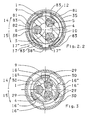
- Fig. 1
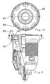
- ein Bohrfutter nach der Erfindung, links in einem Axialschnitt, rechts in einer Seitenansicht, jeweils in der Stellung der Spannbacken bei geringstem Spanndurchmesser und im ungesperrten Futterzustand,
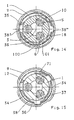
- Fig. 2
- den Schnitt II - II aus
Fig. 1 , und zwar in der Teilfig. 2.1 im ungesperrten, in der Teilfig. 2.2 im gesperrten Futterzustand, - Fig. 3
- den Schnitt III - III aus
Fig. 1 , - Fig. 4
- eine der
Fig. 2.1 entsprechende Darstellung einer weiteren Ausführungsform, - Fig. 5
- eine der
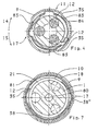
Fig. 1 entsprechende Darstellung einer weiteren Ausführungsform, - Fig. 6
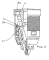
- eine der
Fig. 1 entsprechende Darstellung eines Bohrfutters mit einer axial rückwärtig hinter dem Gewindering angeordneten Abschlußscheibe der Spannhülse sowie mit einer Griffhülse, - Fig. 7
- die Darstellung einer Ausführungsform mit der dem Druckring zugeordneten Sperrverzahnung,
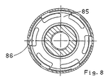
- Fig. 8
- den Schnitt VIII - VIII aus
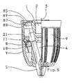
Fig. 1 , - Fig. 9
- eine der
Fig. 1 entsprechende Darstellung einer Ausführungsform mit bis zum axial rückwärtigem Ende des Futterkörpers reichender Spannhülse, - Fig.10
- den Schnitt X - X aus
Fig. 9 , - Fig.11
- eine der
Fig. 1 entsprechende Darstellung einer Ausführungsform mit der gegenüber der Abschlußscheibe eingebördelter Spannhülse, - Fig.12
- eine nochmals andere Ausführungsform zur axialen Sicherung der Spannhülse am axial rückwärtige Ende des Futterkörpers,
- Fig.13
- den Schnitt XIII - XVIII aus
Fig. 12 , - Fig.14
- eine der
Fig. 2.2 entsprechende Darstellung einer Ausführungsform mit einer Sperrfeder erhöhter Dämpfung, - Fig.15
- eine der
Fig. 2.2 entsprechende Darstellung mit einermodifizierten Sperrfeder mit 2 Schaltnoppen, - Fig.16
- eine
Fig. 14 entsprechende Darstellung einerSperrfeder mit 2Rastgliedern und 2 Schaltnoppen, - Fig.17
- eine
Fig. 15 entsprechende Darstellung mit 2 Sperrfedern, - Fig.18
- eine
Fig. 15 entsprechende Darstellung mit einer das Sperrglied und einer das Rastglied tragenden Feder, - Fig.19
- eine zu
Fig. 18 alternative Ausführungsform, - Fig.20
- eine zu
Fig. 18 alternative Ausführungsform mit 3 Feder, - Fig.21
- eine zu
Fig. 20 alternative Ausführungsform, - Fig.22
- eine zu
Fig. 20 alternative Ausführungsform mit 4 Federn, - Fig. 23
- eine der
Fig. 1 entsprechende Darstellung mit einer Verstärkungsrippen aufweisenden Abschlußscheibe, - Fig. 24
- eine Draufsicht auf das Bohrfutter aus
Fig. 23 .
- Fig. 1
- a drill chuck according to the invention, on the left in an axial section, on the right in a side view, in each case in the position of the clamping jaws at the lowest clamping diameter and in the unlocked feed state,
- Fig. 2
- the section II - II off
Fig. 1 , in the subfig. 2.1 in the unlocked, in the Teilfig. 2.2 in the locked feed state, - Fig. 3
- section III - III
Fig. 1 . - Fig. 4
- one of the
Fig. 2.1 corresponding representation of a further embodiment, - Fig. 5
- one of the
Fig. 1 corresponding representation of a further embodiment, - Fig. 6
- one of the
Fig. 1 corresponding representation of a chuck with an axially rearwardly behind the threaded ring arranged closure disc of the clamping sleeve and with a grip sleeve, - Fig. 7
- the representation of an embodiment with the pressure ring associated with the locking teeth,
- Fig. 8
- Section VIII - VIII
Fig. 1 . - Fig. 9
- one of the
Fig. 1 corresponding representation of an embodiment with reaching to the axially rear end of the chuck body clamping sleeve, - Figure 10
- the cut X - X out
Fig. 9 . - Figure 11
- one of the
Fig. 1 corresponding representation of an embodiment with the opposite of the closure plate flared clamping sleeve, - Figure 12
- Yet another embodiment for axially securing the clamping sleeve at the axially rearward end of the chuck body,
- Figure 13
- section XIII - XVIII
Fig. 12 . - Figure 14
- one of the
Fig. 2.2 corresponding representation of an embodiment with a locking spring increased damping, - Figure 15
- one of the
Fig. 2.2 corresponding representation with a modified locking spring with 2 switching nubs, - Figure 16
- a
Fig. 14 corresponding representation of a locking spring with 2 locking members and 2 switching knobs, - Figure 17
- a
Fig. 15 corresponding representation with 2 locking springs, - Figure 18
- a
Fig. 15 corresponding representation with a locking member and a locking member supporting spring, - Figure 19
- one too
Fig. 18 alternative embodiment, - fig.20
- one too
Fig. 18 alternative embodiment with 3 spring, - Figure 21
- one too
Fig. 20 alternative embodiment, - Figure 22
- one too
Fig. 20 alternative embodiment with 4 springs, - Fig. 23
- one of the
Fig. 1 corresponding representation with a reinforcing ribs having closure disk, - Fig. 24
- a plan view of the drill chuck off
Fig. 23 ,
Die in der Zeichnung dargestellten Bohrfutter dienen zur Aufnahme eines nicht dargestellten Bohrers und besitzen je einen Futterkörper 1 zum Anschluß an eine ebenfalls nicht dargestellte Bohrspindel. Zum Anschluß der Bohrspindel weist der Futterkörper 1 eine Gewindeaufnahme 2 auf, an die sich nach vorn ein axialer Durchgang 80 anschließen kann, um die Schläge eines in der Bohrspindel verschiebbar geführten Schlägers oder Döppers unmittelbar auf das Schaftende des in einer Werkzeugaufnahme 4 gehaltenen Bohrers übertragen zu können. Die Bohrfutter besitzen den Bohrer zentrierende, axial führende und/oder einspannende Spannbacken 5, die in der zur Futterachse 3 koaxialen Werkzeugaufnahme 4 zentrisch zur Futterachse 3 verstellbar sind. Die Ausführungsformen zeigen von Hand spannbare Bohrfutter, bei welchen die Spannbacken 5 im Futterkörper 1 geführt und über eine Backenverzahnung 6 mit einem Spanngewinde an einem Gewindering 8 in Eingriff stehen. Zur Verstellung der Spannbacken 5 dient der Gewindering 8, der am Futterkörper 1 axial unverschiebbar und drehbar geführt und axial nach hinten über ein Kugellager 22, gegebenenfalls über einen Druckring 21, am Futterkörper 1 abgestützt ist.The chuck shown in the drawing are used to hold a drill, not shown, and each have a
Um unerwünschte Verstellungen der Spannbacken 5 zu verhindern, kann die Drehstellung des Gewinderings 8 fixiert werden. Dazu dient eine allgemein mit 11 bezeichnete und zwischen dem Gewindering 8 und dem Futterkörper 1 ausgebildete Sperreinrichtung, die aus einem koaxialen Kranz von Sperrausnehmungen 10 auf der Seite des Futterkörpers 1 und auf der Seite des Gewinderings 8 aus mindestens einem Sperrglied 12 besteht, das unter der Kraft einer Sperrfeder in die Sperrausnehmungen 10 greift. Dabei liegen das Sperrglied 12 und die es aufnehmenden Sperrausnehmungen 10 einander in derart geneigten Flankenflächen an, daß diese den Gewindering 8 in der dem Öffnen des Bohrfutters entsprechenden Drehrichtung (Pfeil 14) gegen Verdrehen verriegeln, beim Verdrehen des Gewinderings 8 von Hand mit einem dazu ausreichend großen Drehmoment in der entgegen gesetzten, also dem Schließen des Bohrfutters entsprechenden Drehrichtung (Pfeil 15) das Sperrglied 12 aber gegen die Federkraft aus den Sperrausnehmungen 10 herausdrücken und von Sperrausnehmung 10 zu Sperrausnehmung 10 entlang dem Umfang des Futterkörpers 1 verrutschen lassen. Unter den im Bohrbetrieb auftretenden Schwingungsbeanspruchungen des Bohrfutters bleibt das Bohrfutter aber auch in dieser dem Pfeil 15 entsprechenden Drehrichtung gesperrt. Die für dieses Sperrverhalten unterschiedliche Neigung der Flankenflächen wird auf einfache Weise durch eine sägezahnförmige Gestaltung erreicht, wobei die steilere Flankenfläche der Zahnbrust und die flachere Flankenfläche dem Zahnrücken entspricht.In order to prevent undesired adjustments of the clamping
Das Sperrglied 12 kann zwischen seinen an den Sperrausnehmungen 10 ein- und ausgerückten Zuständen verstellt werden, wozu das Sperrglied 12 durch eine Steuerkurve 35 an einer koaxialen, ebenfalls axial unverschiebbaren Spannhülse 9 verstellbar und entsprechend die Spannhülse 9 relativ zum Gewindering 8 verdrehbar ist. Die Steuerkurve 35 ist durch Stege 81 gebildet, die von der radial äußeren Seite der aus Metall bestehenden Spannhülse 9 nach innen vorstehen und durch eine Bodenplatte 82 verbunden sind, die insbesondere durch die Seitenwände von in die Spannhülse 9 eingeprägten Taschen 83 gebildet sind, wobei eine in die Spannhülse 9 eingeprägte Tasche 83 als Schaltnocken 84 für das Sperrglied 12 fungiert und damit die in Umfangsrichtung der Spannhülse 9 einander gegenüberliegenden Stege der Taschen 83 zur Betätigung der Sperreinrichtung 11 vorgesehen sind.The locking
Bei der Ausführungsform gemäß der
Die Verdrehung der Spannhülse 9 relativ zum Gewindering 8 ist in beiden Drehrichtungen (Pfeile 14, 15) formschlüssig begrenzt, wozu Anschläge 16', 16" vorgesehen sind. Durch Verdrehen der Spannhülse 9 in der dem Schließen des Bohrfutters entsprechenden Drehrichtung (Pfeil 15) verstellt sich das Sperrglied 12 aus dem ausgerückten Zustand in den eingerückten Zustand und umgekehrt, also durch Verdrehen der Spannhülse 9 in der dem Öffnen des Bohrfutters entsprechenden Drehrichtung (Pfeil 14) aus dem eingerückten Zustand in den ausgerückten Zustand.The rotation of the clamping
Zwischen der Spannhülse 9 und dem Gewindering 8 ist eine allgemein mit 17 bezeichnete Rasteinrichtung vorgesehen, die in Umfangsrichtung zwei Raststellungen aufweist, wobei sich in der einen Raststellung das Sperrglied 12 in dem an den Sperrausnehmungen 10 eingerückten Zustand und in der anderen Raststellung im ausgerückten Zustand befindet, wie ein Vergleich des Figurenpaares 2.1 und 2.2 erkennen läßt. Dabei sind die Raststellungen durch den Eingriff eines von der Kraft einer Rastfeder beaufschlagten Rastgliedes 38" auf der Seite des Gewinderings 8 in entsprechend an der Spannhülse 9 angeordnete Rastaufnahmen 17" gebildet, die Teil der Steuerkurve 35 und gleichfalls durch in die Spannhülse 9 eingeprägte Taschen 83 verwirklicht sind. Das Rastglied 38" ist insbesondere durch einen Rastnocken der Rastfeder gebildet. Die Sperrfeder und die Rastfeder sind in den
Der Gewindering 8 besitzt den eine Führung für die Spannhülse 9 bildenden koaxialen Zwischenring 18, der die gewinderingseitigen Teile der Anschläge 16', 16" für die Spannhülse und außerdem den Federbügel 38 trägt, sowie einen Kragenteil 18' umfaßt, der den das Spanngewinde tragenden Teil des Gewinderings 8 drehfest umschließt. Dabei besteht der das Spanngewinde tragende Teil des Gewinderings 8 aus zwei umfangsmäßig geteilten, nämlich zunächst an jeder Teilung durch eine Bohrung geschwächten und dann gebrochenen Ringhälften, die in einer Ringnut des Futterkörpers 1 gegeneinander zusammengesetzt und durch den Kragenteil 18' am Futterkörper 1 zusammengehalten sind. Selbstverständlich kann aber der Gewindering 8 auch einstückig ausgebildet sein, was jedoch in der Zeichnung nicht weiter dargestellt ist.The threaded
In allen Fällen besitzt der Gewindering 8 bzw. Zwischenring 18 zur radialen Führung der Spannhülse 9 eine kreiszylindrische Außenfläche, der die Spannhülse 9 mit einer entsprechend kreiszylindrischen Innenfläche anliegt.In all cases, the threaded
In den Ausführungsbeispielen wird die in axialer Richtung ungeteilt ausgebildete Spannhülse 9 axial von vorn her über den Futterkörper 1 auf den am Futterkörper 1 fertig montierten Gewindering 8 aufgeschoben werden, worauf die Spannhülse 9 in ihrer aufgeschobenen Endlage axial gesichert wird. Die Sicherung der Spannhülse 9 gegen axiale Verschiebungen erfolgt im Bereich axial hinter dem Gewindering 8 am Futterkörper 1 an einer mit dem Futterkörper 1 verbundenen Abschlußscheibe 85, die auch zur radialen Führung der Spannhülse 9 im Bereich ihres rückwärtigen Ringendes beiträgt. Im einzelnen sind an der Abschlußscheibe 85 sich in Umfangsrichtung erstreckende, radial federnde Zungen 86 ausgebildet (
Axial vor der Spannhülse 9 ist ein ihr gegenüber frei verdrehbarer Anschlagring 50 vorgesehen, der am Futterkörper 1 axial unverschiebbar und drehbar gelagert ist, wozu der Anschlagring 50 axial nach hinten an einer Ringschulter 51 des Futterkörpers 1 und axial nach vorn an einem Sprengring 52 gehalten ist, der in einer Ringnut am Futterkörper 1 sitzt. Der Anschlagring 50 schützt die Spannhülse 9 davor, beim Durchbohren einer Wand an die Wand anzustoßen und dadurch gebremst zu werden, was dazu führen könnte, daß das Bohrfutter sich so festzieht, daß es nur noch mit Mühe wieder geöffnet werden kann. Auch schützt der Anschlagring 50 die Spannhülse 9 gegen größere axiale Belastung von vorn, so daß die axiale Abstützung der Spannhülse 9 nach hinten entsprechend gering beansprucht wird. Weiterhin ist der Anschlagring 50 als Kappe 51 bzw Staubschutzkappe nutzbar, die die Steuerkurve 35 überdeckt.Axial in front of the clamping
Für die Anschläge 16', 16" zur Drehbegrenzung zwischen der Spannhülse 9 und dem Gewindering 8 sind in den Ausführungsbeispielen allgemein mit 29 bezeichnete Anschlagstücke und eine das Anschlagstück 29 aufnehmende Aussparung 30 vorgesehen, wobei das Anschlagstück 29 an den Enden des Drehwegs jeweils mit einer der die Aussparung 30 in Umfangsrichtung begrenzenden beiden Stirnflächen 16', 16" zum Anschlag kommt. In den Ausführungsbeispielen sind jeweils drei solche gleichmäßig über den Futterumfang verteilt angeordnete Anschlagstücke 29 bzw. Aussparungen 30 vorhanden. Im einzelnen können die Anschlagstücke 29 als Wandstücke des Zwischenrings 18 ausgebildet sein, die vom vorderen Rand des Zwischenrings 18 axial nach vorn in die auf der Wandinnenseite der Spannhülse 9 ausgebildeten Aussparungen 30 vorstehen.For the
Der Federbügel 38 bildet einen sich in Umfangsrichtung erstreckenden Federarm 36, der am freien Armende das Sperrglied 12 aufweist. Um bei lang ausgedehntem Federarm 36 eine zu weiche Federcharakteristik zu vermeiden, ist bei dem Bohrfutter gemäß
Durch die Vorspannung des Federbügels 38 wird das Sperrglied 12 außer Eingriff an den Sperrausnehmungen 10 gehalten; im Sperrzustand muß es über die Steuerkurve 35 in die Sperrausnehmungen 10 hineingedrückt werden. Jedenfalls beim Sperreingriff des Sperrglieds 12 in die Sperrausnehmungen 10 liegen die Federstege 34 des Federbügels 38 federnd am Kranz der Sperrausnehmungen 10 an, so daß sich der Federbügel 38 in seiner Lage im Zwischenring 18 selbsttätig justiert. In diesem Sinne günstig erweist sich auch ein Federschenkel 71, den der Federbügel 38 mit seinem dem Vorsprung 38" abgewandten Ende bildet und der ebenfalls unter Vorspannung dem Kranz der Sperrausnehmungen 10 anliegt. Die dem Futterkörper 1 anliegenden beiden Federstege 34 und der Federschenkel 71 üben im übrigen eine Bremswirkung aus, durch die beim Bohrbetrieb auftretende Vibrationen an Futterkörper 1, Gewindering 8 bzw. Zwischenring 18 und Spannhülse 9 gedämpft werden.By the bias of the
In den Ausführungsbeispielen sind die Anschläge 16', 16", die Sperreinrichtung 11 und die Rasteinrichtung 17 axial vor dem Spanngewinde angeordnet. Selbstverständlich liegt es im Rahmen der Erfindung, diese Teile, zumindest einige davon, axial hinter dem Spanngewinde vorzusehen, wobei sich insbesondere der körperfeste Druckring 21 dazu anbietet, mit den Sperrausnehmungen 10 versehen zu werden.In the exemplary embodiments, the
Im folgenden wird die Funktionsweise des erfindungsgemäßen Bohrfutters anhand des Ausführungsbeispiels nach den
Die
Um in einfacher und kostengünstiger Weise die zur Verstellung des Sperrgliedes 12 notwendige Steuerkurve 35 in der Spannhülse 9 ausbilden zu können, wird diese durch mindestens einen radial von außen gegen die Spannhülse 9 gepreßten Stempel gefertigt, wobei sich mindestens eine Tasche 17 ausbildet, die vier Stege 81 aufweist, die von der radial äußeren Seite der Spannhülse 9 nach innen vorstehen und durch eine Bodenplatte 82 verbunden sind.To train in a simple and cost-effective manner necessary for adjusting the locking
Bei der Fertigung der Spannhülse 9 wird zum Schutz von deren Form in die hohle Spannhülse 9 ein zur Anlage am Innenumfang der Spannhülse 9 kommender zylindrischer Stab eingeführt und radial von außen nach innen der Stempel gegen die Spannhülse 9 gepreßt, der die Tasche 83 formt. Um dabei einen möglichst weitgehenden Schutz der ursprünglichen Hülseform zu erzielen, wird der Stab axial bis über die einzuprägende Tasche 83 hinaus eingeführt und dann erst radial bis zur Anlage an den Innenumfang aufgeweitet, wobei in dem Stab Aufnahmen ausgebildet sind, die die Form der zu formenden Taschen 83 aufweisen und als Matrize wirken, in die der Stempel das Material der Spannhülse 9 einformt. Nach Ausbildung der Taschen 83 kann der Stab wieder verengt und aus der Spannhülse 9 entfernt werden. Da die in Umfangsrichtung liegenden Stege 81 der Tasche 83 zur Verstellung genutzt werden, ist es gleichfalls möglich, daß zur Ausbildung der als in axialer Richtung orientierten Nut 83' ausgebildeten Tasche 83 der Stempel axial gegen die Spannhülse 9 gepreßt wird.In the manufacture of the clamping
Claims (23)
- A drilling chuck comprising a chuck body (1) which can be connected to a drilling spindle, clamping jaws (5) which form between them a receiving means for the drilling tool and which are displaceable in guide receiving means extending inclinedly with respect to the chuck axis (3) for opening and closing the drilling chuck, by a screwthreaded ring (8) which is guided rotatably and axially immovably on the chuck body (1), and a clamping sleeve (9) serving for displacement of the clamping jaws (5) by rotation of the screwthreaded ring (8), characterised in that in the region axially behind the screwthreaded ring (8), that is to say on the side towards the drilling spindle, the clamping sleeve (9) is axially secured to a closure disc (85) which is connected to the chuck body (1) and which provides a spring action, wherein the closure disc (85) is arranged as a closure of the clamping sleeve (9).
- A drilling chuck according to claim 1 characterised in that in the region of the rearward annular end of the clamping sleeve (9) the closure disc (85) engages into a groove (87) on the clamping sleeve (9).
- A drilling chuck according to claim 1 or claim 2 characterised in that the clamping sleeve (9) covers over the chuck body (1) as far as the rearward end thereof and that the closure disk (85) is fixed to the rearward end of the chuck body (1).
- A drilling chuck according to one of claims 1 to 3 characterised in that a disc flange (88) is formed on the closure disc (85).
- A drilling chuck according to claim 4 characterised in that the disc
- A drilling chuck according to one of claims 2 to 5 characterised in that radially resilient tongues (86) are provided on the closure disc (85), for engagement into the groove (87) on the clamping sleeve (9).
- A drilling chuck according to one of claims 1 to 6 characterised in that openings (104) are provided in the closure disc (85).
- A drilling chuck according to claim 7 characterised in that the openings (104) are arranged radially adjacent to the flange segments (89).
- A drilling chuck according to claim 7 characterised in that the openings (104) are arranged adjacent to the tongues (86).
- A drilling chuck according to one of claims 1 to 9 characterised in that the clamping sleeve (9) has a control cam (35) for actuation of a locking device (11) for preventing or enabling rotation of the screwthreaded ring (8).
- A drilling chuck according to claim 10 characterised in that the control cam (35) is formed by limbs (81) which project inwardly from the radially outward side of the clamping sleeve (9) which comprises metal.
- A drilling chuck according to claim 11 characterised in that the limbs (81) are formed by the side walls of at least one pocket (83) which is impressed into the clamping sleeve (9).
- A drilling chuck according to claim 11 or claim 12 characterised in that the limbs (81) of the pocket (83), which limbs are in mutually opposite relationship in the peripheral direction of the clamping sleeve (9), are provided for actuation of the locking device (11).
- A drilling chuck according to one of claims 10 to 13 characterised in that the control cam (35) is covered over by a cap (51).
- A drilling chuck according to claim 14 characterised in that the cap (41) is formed by a dust protection cap supported axially an the chuck body (1).
- A drilling chuck according to one of claims 10 to 15 characterised in that the locking device (11) comprises a coaxial ring of locking recesses (10) and at least one locking member (12) which can be engaged into the locking recesses (10) under the force of a locking spring by the control cam (35), wherein the locking member (12) and the locking recesses (10) bear against each other at flank surfaces inclined in such a way that they lock the screwthreaded ring (8) to prevent rotation in the direction of rotation corresponding to opening of the drilling chuck and upon rotation in the other direction of rotation they urge the locking member against the force of the locking spring out of the locking recesses (10), and that a switching projection (84) is provided by one of the pockets (83) impressed into the clamping sleeve (9), for spring stressing purposes.
- A drilling chuck according to claim 16 characterised in that the screwthreaded ring (8) is non-rotatably connected to a coaxial intermediate ring (18) which carries the locking spring and the locking member (12) and that the intermediate ring (18) is rotatable relative to the clamping sleeve (9) limitedly by abutments (16', 16").
- A drilling chuck according to claim 16 or claim 17 characterised in that there is provided a latching device (17) having two latching positions in the peripheral direction, wherein the latching member (38') formed by a latching projection of a latching spring is in the one latching position (17') when the locking member (12) is engaged into the locking recesses (10) and is in the other latching position (17") when the locking member (12) is disengaged, and that the control cam (35) includes the two latching positions (17', 17").
- A drilling chuck according to claim 18 characterised in that provided on the locking spring are two locking members (12) for simultaneous engagement into the edge tooth arrangement for joint force transmission, a respective pocket (83) being associated as a switching projection (84) with each locking member.
- A drilling chuck according to claim 19 characterised in that the locking spring is arranged in the intermediate ring (18) with a play permitting alignment of the locking members (12) with respect to the locking recess (10).
- A drilling chuck according to claim 19 characterised in that the two locking members (12) are arranged at the ends of the locking spring, that the locking member (12) which leads in the direction of rotation corresponding to opening of the drilling chuck is offset in the direction of the locking recesses (10) and that the other locking member (12) is of a loop-shaped configuration for acting on the flank surface which is coincident with respect to the front locking member (12).
- A drilling chuck according to one of claims 1 to 21 characterised in that the closure disc (85) has reinforcing ribs (105) on its flat side.
- A drilling chuck according to claim 22 characterised in that the reinforcing ribs (105) are arranged centrally within the flange segments (89).
Priority Applications (6)
| Application Number | Priority Date | Filing Date | Title |
|---|---|---|---|
| EP05001895A EP1547709A3 (en) | 2000-07-03 | 2001-03-26 | Drill Chuck |
| EP01107531A EP1170079B2 (en) | 2000-07-03 | 2001-03-26 | Drill chuck |
| TW090110862A TW592852B (en) | 2000-07-03 | 2001-05-07 | Drill chuck |
| US09/887,869 US6581942B2 (en) | 2000-07-03 | 2001-06-22 | Drill chuck |
| JP2001197338A JP4828729B2 (en) | 2000-07-03 | 2001-06-28 | Drill chuck provided with a tightening casing cylinder having a bent portion for switching and adjustment |
| CN01122145.3A CN1227089C (en) | 2000-07-03 | 2001-07-03 | Drill chuck |
Applications Claiming Priority (3)
| Application Number | Priority Date | Filing Date | Title |
|---|---|---|---|
| EP00113184 | 2000-07-03 | ||
| EP20000113184 EP1170078B1 (en) | 2000-07-03 | 2000-07-03 | Drilling chuck with a locknut having a steering-curve |
| EP01107531A EP1170079B2 (en) | 2000-07-03 | 2001-03-26 | Drill chuck |
Related Child Applications (2)
| Application Number | Title | Priority Date | Filing Date |
|---|---|---|---|
| EP05001895A Division EP1547709A3 (en) | 2000-07-03 | 2001-03-26 | Drill Chuck |
| EP05001895.1 Division-Into | 2005-01-31 |
Publications (3)
| Publication Number | Publication Date |
|---|---|
| EP1170079A1 EP1170079A1 (en) | 2002-01-09 |
| EP1170079B1 EP1170079B1 (en) | 2005-10-05 |
| EP1170079B2 true EP1170079B2 (en) | 2010-10-06 |
Family
ID=26071064
Family Applications (2)
| Application Number | Title | Priority Date | Filing Date |
|---|---|---|---|
| EP01107531A Expired - Lifetime EP1170079B2 (en) | 2000-07-03 | 2001-03-26 | Drill chuck |
| EP05001895A Withdrawn EP1547709A3 (en) | 2000-07-03 | 2001-03-26 | Drill Chuck |
Family Applications After (1)
| Application Number | Title | Priority Date | Filing Date |
|---|---|---|---|
| EP05001895A Withdrawn EP1547709A3 (en) | 2000-07-03 | 2001-03-26 | Drill Chuck |
Country Status (5)
| Country | Link |
|---|---|
| US (1) | US6581942B2 (en) |
| EP (2) | EP1170079B2 (en) |
| JP (1) | JP4828729B2 (en) |
| CN (1) | CN1227089C (en) |
| TW (1) | TW592852B (en) |
Families Citing this family (45)
| Publication number | Priority date | Publication date | Assignee | Title |
|---|---|---|---|---|
| CN1217762C (en) * | 2001-06-10 | 2005-09-07 | 山东威达机械股份有限公司 | Self-locking clamping chuck of drill bit |
| US6824141B1 (en) * | 2001-08-30 | 2004-11-30 | Yukiwa Seiko Kabushiki Kaisha | Chuck device |
| US6959931B2 (en) * | 2001-08-30 | 2005-11-01 | Yukiwa Seiko Inc. | Keyless chuck and associated method |
| US6860488B2 (en) * | 2001-10-10 | 2005-03-01 | Rohm Gmbh | Drill chuck with front-end shield |
| JP4015857B2 (en) * | 2002-01-18 | 2007-11-28 | ユキワ精工株式会社 | Chuck device |
| JP4053301B2 (en) * | 2002-01-31 | 2008-02-27 | ユキワ精工株式会社 | Chuck device |
| DE10226429A1 (en) * | 2002-06-13 | 2003-12-24 | Roehm Gmbh | chuck |
| DE10237750A1 (en) * | 2002-08-17 | 2004-02-26 | Röhm Gmbh | Chucks, in particular for hammer drill, comprising threaded ring provided with groove for press fitting of sleeve |
| FR2847180B1 (en) * | 2002-11-18 | 2005-02-11 | Amyot Ets Sa | TOOL HOLDER MECHANISM WITH LATCHING SYSTEM |
| CN2582790Y (en) * | 2002-11-25 | 2003-10-29 | 山东威达机械股份有限公司 | Self-locking drill chuck |
| JP4294945B2 (en) * | 2002-12-06 | 2009-07-15 | ユキワ精工株式会社 | Chuck device |
| CN2602857Y (en) | 2003-03-25 | 2004-02-11 | 山东威达机械股份有限公司 | Self-locking type drill chuck |
| US20060261563A1 (en) * | 2003-03-25 | 2006-11-23 | Guimo Yang | Self-locking drill chuck |
| US7451990B2 (en) * | 2004-04-29 | 2008-11-18 | Jacobs Chuck Manufacturing Company | Chuck with torque indicator |
| CN2715890Y (en) * | 2004-08-03 | 2005-08-10 | 山东威达机械股份有限公司 | Self-locking drill chuck with noise |
| DE102004044824A1 (en) * | 2004-09-16 | 2006-03-23 | Röhm Gmbh | chuck |
| US20070063455A1 (en) * | 2004-09-17 | 2007-03-22 | Zhang Qiang J | Fastener with nutating gear reduction |
| US7331584B2 (en) * | 2004-09-17 | 2008-02-19 | Black & Decker Inc. | Chuck with nutating gear reduction |
| JP4787314B2 (en) * | 2005-03-19 | 2011-10-05 | ロェーム ゲーエムベーハー | Drill chuck |
| CN2787343Y (en) * | 2005-05-13 | 2006-06-14 | 浙江三鸥机械股份有限公司 | Self-locking hand-operated drill chuck |
| US7708288B2 (en) * | 2005-05-18 | 2010-05-04 | Jacobs Chuck Manufacturing Company | Locking chuck |
| US7472913B2 (en) | 2005-06-09 | 2009-01-06 | Jacobs Chuck Manufacturing Company | Drill chuck |
| US7837200B2 (en) | 2005-07-01 | 2010-11-23 | Jacobs Chuck Manufacturing Company | Chuck |
| US7527273B2 (en) * | 2005-09-02 | 2009-05-05 | Jacobs Chuck Manufacturing Company | Locking chuck |
| CN2832373Y (en) * | 2005-09-09 | 2006-11-01 | 浙江三鸥机械股份有限公司 | Locking drill chuck |
| CN100578036C (en) * | 2005-09-28 | 2010-01-06 | 山东威达机械股份有限公司 | One-way clutch and clamping structure of handle tool therewith |
| CN2832376Y (en) * | 2005-09-30 | 2006-11-01 | 浙江三鸥机械股份有限公司 | Self-locking hand-screwed drill chuck |
| US7637510B2 (en) * | 2005-10-12 | 2009-12-29 | Shandong Weida Machinery Company Limited | Chuck with gripping mechanism stop |
| DE102005058657A1 (en) * | 2005-12-07 | 2007-06-14 | Röhm Gmbh | chuck |
| FR2897789B1 (en) | 2006-02-27 | 2008-05-09 | Amyot Sa Sa Ets | TOOL HOLDER CHUCK FOR THE EQUIPMENT OF A ROTATING MACHINE WITH RADIAL LOCKING AND AXIAL SEQUENCE MECHANISMS |
| JP2010514574A (en) * | 2006-12-23 | 2010-05-06 | ロェーム ゲーエムベーハー | Drill chuck |
| CN201012399Y (en) * | 2007-04-10 | 2008-01-30 | 浙江三鸥机械股份有限公司 | Novel self-locking type clamping head of closefisted drill |
| US8061718B2 (en) * | 2007-07-27 | 2011-11-22 | Robert Bosch Gmbh | Toolless bitholder for spiral saws |
| US8740227B2 (en) * | 2009-01-19 | 2014-06-03 | Shandong Weida Machinery Co., Ltd. | Force increasing self-locking drill chuck and self-locking mechanism thereof |
| US8777232B2 (en) | 2009-07-29 | 2014-07-15 | Jacobs Chuck Manufacturing Company | Self-tightening chuck with a radial lock |
| CN103781578B (en) * | 2011-04-05 | 2016-08-31 | 米沃奇电动工具公司 | Automatically chuck is adjusted |
| US10086442B2 (en) * | 2012-07-17 | 2018-10-02 | Weihai Dawang Hardware Products Limited | Drill chuck |
| DE102012110809A1 (en) * | 2012-11-12 | 2014-05-15 | Röhm Gmbh | chuck |
| DE202013101255U1 (en) | 2013-03-25 | 2013-04-10 | Röhm Gmbh | chuck |
| DE102015102241A1 (en) * | 2015-02-17 | 2016-08-18 | Röhm Gmbh | chuck |
| US10213897B2 (en) * | 2016-04-01 | 2019-02-26 | Robert Bosch Tool Corporation | Clamping apparatus with control mechanism for spring-actuated lever |
| JP6787571B2 (en) * | 2016-12-06 | 2020-11-18 | ユキワ精工株式会社 | Chuck device |
| USD878887S1 (en) | 2018-03-09 | 2020-03-24 | Milwaukee Electric Tool Corporation | Rotary power tool chuck |
| USD983635S1 (en) * | 2020-06-03 | 2023-04-18 | Techtronic Cordless Gp | Rotary power tool chuck |
| CN111843642B (en) * | 2020-07-16 | 2022-09-13 | 天辰兰德(山东)科技服务有限公司 | Rolling pin equipment of polishing |
Citations (8)
| Publication number | Priority date | Publication date | Assignee | Title |
|---|---|---|---|---|
| US4930793A (en) † | 1987-11-09 | 1990-06-05 | Emu-Esu Industrial Co., Ltd. | Keyless chuck |
| US5145193A (en) † | 1990-07-21 | 1992-09-08 | Roehm Guenter H | Lockable drill chuck |
| US5215317A (en) † | 1992-05-18 | 1993-06-01 | Jacobs Chuck Technology Corp. | Keyless chuck |
| US5261679A (en) † | 1991-09-12 | 1993-11-16 | Jacobs Japan, Inc. | Keyless type tool chuck |
| US5816582A (en) † | 1995-08-11 | 1998-10-06 | Power Tool Holders Incor. | Chuck |
| US5829761A (en) † | 1996-01-17 | 1998-11-03 | Roehm; Guenter Horst | Drill chuck |
| US5957469A (en) † | 1996-09-25 | 1999-09-28 | Power Tool Holders, Inc. | Spring chuck |
| EP1029621A1 (en) † | 1999-02-20 | 2000-08-23 | Röhm GmbH | Drill chuck |
Family Cites Families (12)
| Publication number | Priority date | Publication date | Assignee | Title |
|---|---|---|---|---|
| DE7723640U1 (en) * | 1977-07-29 | 1979-01-25 | Robert Bosch Gmbh, 7000 Stuttgart | DRILL CHUCK |
| US4660841A (en) * | 1985-01-14 | 1987-04-28 | Chouinard Michael J | Hand tightenable device for holding a cutting implement |
| JPH04226819A (en) * | 1990-07-21 | 1992-08-17 | Guenter H Roehm | Drill chuck |
| US5232230A (en) * | 1992-09-28 | 1993-08-03 | Lin Pi Chu | Chuck assembly for a drilling apparatus |
| DE4238503C1 (en) * | 1992-11-14 | 1993-11-25 | Roehm Guenter H | Drill chuck |
| US5692759A (en) * | 1994-04-12 | 1997-12-02 | Synergy Medical Products, Inc. | Keyless chuck operation device |
| DE4419825A1 (en) * | 1994-06-07 | 1995-12-14 | Bosch Gmbh Robert | Hand drill, in particular hammer drill and its tool holder |
| DE4438991C5 (en) * | 1994-10-31 | 2009-07-30 | Röhm Gmbh | chuck |
| US5984320A (en) * | 1996-01-22 | 1999-11-16 | Nakamura; Daijiro | Tool chuck |
| JPH09262707A (en) * | 1996-01-22 | 1997-10-07 | Jacobs Japan Inc | Tool chuck |
| US5816583A (en) * | 1996-12-04 | 1998-10-06 | Power Tool Holders, Inc. | Integral locking sleeve chuck |
| JP2000061716A (en) * | 1998-08-13 | 2000-02-29 | Yukiwa Seiko Inc | Chuck device |
-
2001
- 2001-03-26 EP EP01107531A patent/EP1170079B2/en not_active Expired - Lifetime
- 2001-03-26 EP EP05001895A patent/EP1547709A3/en not_active Withdrawn
- 2001-05-07 TW TW090110862A patent/TW592852B/en not_active IP Right Cessation
- 2001-06-22 US US09/887,869 patent/US6581942B2/en not_active Expired - Fee Related
- 2001-06-28 JP JP2001197338A patent/JP4828729B2/en not_active Expired - Fee Related
- 2001-07-03 CN CN01122145.3A patent/CN1227089C/en not_active Expired - Fee Related
Patent Citations (8)
| Publication number | Priority date | Publication date | Assignee | Title |
|---|---|---|---|---|
| US4930793A (en) † | 1987-11-09 | 1990-06-05 | Emu-Esu Industrial Co., Ltd. | Keyless chuck |
| US5145193A (en) † | 1990-07-21 | 1992-09-08 | Roehm Guenter H | Lockable drill chuck |
| US5261679A (en) † | 1991-09-12 | 1993-11-16 | Jacobs Japan, Inc. | Keyless type tool chuck |
| US5215317A (en) † | 1992-05-18 | 1993-06-01 | Jacobs Chuck Technology Corp. | Keyless chuck |
| US5816582A (en) † | 1995-08-11 | 1998-10-06 | Power Tool Holders Incor. | Chuck |
| US5829761A (en) † | 1996-01-17 | 1998-11-03 | Roehm; Guenter Horst | Drill chuck |
| US5957469A (en) † | 1996-09-25 | 1999-09-28 | Power Tool Holders, Inc. | Spring chuck |
| EP1029621A1 (en) † | 1999-02-20 | 2000-08-23 | Röhm GmbH | Drill chuck |
Also Published As
| Publication number | Publication date |
|---|---|
| JP4828729B2 (en) | 2011-11-30 |
| TW592852B (en) | 2004-06-21 |
| CN1227089C (en) | 2005-11-16 |
| EP1547709A3 (en) | 2005-08-31 |
| JP2002052408A (en) | 2002-02-19 |
| EP1547709A2 (en) | 2005-06-29 |
| EP1170079A1 (en) | 2002-01-09 |
| US6581942B2 (en) | 2003-06-24 |
| CN1330992A (en) | 2002-01-16 |
| EP1170079B1 (en) | 2005-10-05 |
| US20020000698A1 (en) | 2002-01-03 |
Similar Documents
| Publication | Publication Date | Title |
|---|---|---|
| EP1170079B2 (en) | Drill chuck | |
| EP1055472B1 (en) | Drill chuck | |
| EP0677348B1 (en) | Chuck | |
| EP1799396B1 (en) | Replacement device for clamping heads comprising a plurality of clamping jaws | |
| EP0598176B1 (en) | Drilling chuck | |
| EP1029621B1 (en) | Drill chuck | |
| WO2003103901A2 (en) | Chuck for receiving tools operated by rotating around the axis thereof | |
| DE10261748A1 (en) | punching tool | |
| DE4445858A1 (en) | Drilling device | |
| DE4405697A1 (en) | Tool holder for a hammer and / or chisel hammer | |
| EP0716896B1 (en) | Drilling device | |
| EP1709930A1 (en) | Motor element, in particular medical handpice with a collet | |
| EP1170078B1 (en) | Drilling chuck with a locknut having a steering-curve | |
| DE19923006C2 (en) | Chuck for interchangeable tool inserts | |
| DE102005048167B4 (en) | chuck | |
| DE4448025B4 (en) | Chuck for drill with hammer action - has adaptor sleeve that turns in relation to ring within boundaries given by first stops locking element, and engaging mechanism |
Legal Events
| Date | Code | Title | Description |
|---|---|---|---|
| PUAI | Public reference made under article 153(3) epc to a published international application that has entered the european phase |
Free format text: ORIGINAL CODE: 0009012 |
|
| AK | Designated contracting states |
Kind code of ref document: A1 Designated state(s): AT BE CH CY DE DK ES FI FR GB GR IE IT LI LU MC NL PT SE TR Kind code of ref document: A1 Designated state(s): CH DE FR GB LI |
|
| AX | Request for extension of the european patent |
Free format text: AL;LT;LV;MK;RO;SI |
|
| 17P | Request for examination filed |
Effective date: 20020605 |
|
| AKX | Designation fees paid |
Free format text: CH DE FR GB LI |
|
| GRAP | Despatch of communication of intention to grant a patent |
Free format text: ORIGINAL CODE: EPIDOSNIGR1 |
|
| GRAS | Grant fee paid |
Free format text: ORIGINAL CODE: EPIDOSNIGR3 |
|
| GRAA | (expected) grant |
Free format text: ORIGINAL CODE: 0009210 |
|
| AK | Designated contracting states |
Kind code of ref document: B1 Designated state(s): CH DE FR GB LI |
|
| PG25 | Lapsed in a contracting state [announced via postgrant information from national office to epo] |
Ref country code: GB Free format text: LAPSE BECAUSE OF FAILURE TO SUBMIT A TRANSLATION OF THE DESCRIPTION OR TO PAY THE FEE WITHIN THE PRESCRIBED TIME-LIMIT Effective date: 20051005 |
|
| REG | Reference to a national code |
Ref country code: GB Ref legal event code: FG4D Free format text: NOT ENGLISH |
|
| REG | Reference to a national code |
Ref country code: CH Ref legal event code: EP |
|
| REF | Corresponds to: |
Ref document number: 50107596 Country of ref document: DE Date of ref document: 20051110 Kind code of ref document: P |
|
| PG25 | Lapsed in a contracting state [announced via postgrant information from national office to epo] |
Ref country code: CH Free format text: LAPSE BECAUSE OF NON-PAYMENT OF DUE FEES Effective date: 20060331 Ref country code: LI Free format text: LAPSE BECAUSE OF NON-PAYMENT OF DUE FEES Effective date: 20060331 |
|
| GBV | Gb: ep patent (uk) treated as always having been void in accordance with gb section 77(7)/1977 [no translation filed] |
Effective date: 20051005 |
|
| ET | Fr: translation filed | ||
| PLBI | Opposition filed |
Free format text: ORIGINAL CODE: 0009260 |
|
| 26 | Opposition filed |
Opponent name: POWER TOOL HOLDERS INC. Effective date: 20060704 |
|
| PLAX | Notice of opposition and request to file observation + time limit sent |
Free format text: ORIGINAL CODE: EPIDOSNOBS2 |
|
| REG | Reference to a national code |
Ref country code: CH Ref legal event code: PL |
|
| PLBB | Reply of patent proprietor to notice(s) of opposition received |
Free format text: ORIGINAL CODE: EPIDOSNOBS3 |
|
| RAP2 | Party data changed (patent owner data changed or rights of a patent transferred) |
Owner name: EVONIK ROEHM GMBH |
|
| RAP2 | Party data changed (patent owner data changed or rights of a patent transferred) |
Owner name: ROEHM GMBH |
|
| APAH | Appeal reference modified |
Free format text: ORIGINAL CODE: EPIDOSCREFNO |
|
| APBP | Date of receipt of notice of appeal recorded |
Free format text: ORIGINAL CODE: EPIDOSNNOA2O |
|
| PLAB | Opposition data, opponent's data or that of the opponent's representative modified |
Free format text: ORIGINAL CODE: 0009299OPPO |
|
| APBQ | Date of receipt of statement of grounds of appeal recorded |
Free format text: ORIGINAL CODE: EPIDOSNNOA3O |
|
| PLBP | Opposition withdrawn |
Free format text: ORIGINAL CODE: 0009264 |
|
| APBU | Appeal procedure closed |
Free format text: ORIGINAL CODE: EPIDOSNNOA9O |
|
| PUAH | Patent maintained in amended form |
Free format text: ORIGINAL CODE: 0009272 |
|
| STAA | Information on the status of an ep patent application or granted ep patent |
Free format text: STATUS: PATENT MAINTAINED AS AMENDED |
|
| 27A | Patent maintained in amended form |
Effective date: 20101006 |
|
| AK | Designated contracting states |
Kind code of ref document: B2 Designated state(s): CH DE FR GB LI |
|
| PGFP | Annual fee paid to national office [announced via postgrant information from national office to epo] |
Ref country code: FR Payment date: 20120403 Year of fee payment: 12 |
|
| PGFP | Annual fee paid to national office [announced via postgrant information from national office to epo] |
Ref country code: DE Payment date: 20120110 Year of fee payment: 12 |
|
| REG | Reference to a national code |
Ref country code: FR Ref legal event code: ST Effective date: 20131129 |
|
| REG | Reference to a national code |
Ref country code: DE Ref legal event code: R119 Ref document number: 50107596 Country of ref document: DE Effective date: 20131001 |
|
| PG25 | Lapsed in a contracting state [announced via postgrant information from national office to epo] |
Ref country code: FR Free format text: LAPSE BECAUSE OF NON-PAYMENT OF DUE FEES Effective date: 20130402 Ref country code: DE Free format text: LAPSE BECAUSE OF NON-PAYMENT OF DUE FEES Effective date: 20131001 |