EP1170566A2 - Grid for intercepting solid particles circulating in a heat exchanger for cleaning, and control device for such particles using such a grid - Google Patents
Grid for intercepting solid particles circulating in a heat exchanger for cleaning, and control device for such particles using such a grid Download PDFInfo
- Publication number
- EP1170566A2 EP1170566A2 EP01401627A EP01401627A EP1170566A2 EP 1170566 A2 EP1170566 A2 EP 1170566A2 EP 01401627 A EP01401627 A EP 01401627A EP 01401627 A EP01401627 A EP 01401627A EP 1170566 A2 EP1170566 A2 EP 1170566A2
- Authority
- EP
- European Patent Office
- Prior art keywords
- grid
- elements
- grid according
- cleaning
- wings
- Prior art date
- Legal status (The legal status is an assumption and is not a legal conclusion. Google has not performed a legal analysis and makes no representation as to the accuracy of the status listed.)
- Withdrawn
Links
Images
Classifications
-
- F—MECHANICAL ENGINEERING; LIGHTING; HEATING; WEAPONS; BLASTING
- F28—HEAT EXCHANGE IN GENERAL
- F28G—CLEANING OF INTERNAL OR EXTERNAL SURFACES OF HEAT-EXCHANGE OR HEAT-TRANSFER CONDUITS, e.g. WATER TUBES OR BOILERS
- F28G1/00—Non-rotary, e.g. reciprocated, appliances
- F28G1/12—Fluid-propelled scrapers, bullets, or like solid bodies
Definitions
- the present invention relates generally to exchangers heat, and, for example, tubular heat exchangers forming condensers, which are continuously cleaned by solid elements, in practice in the form of a ball and made for example of foam rubber, systematically put into circulation for this purpose in one of the flows concerned.
- the tubes are cleaned by injecting upstream of the exchanger solid cleaning items, usually rubber balls foam of density substantially equal to that of cooling water and diameter very slightly greater than the internal diameter of the tubes to be cleaned.
- the exchanger solid cleaning items usually rubber balls foam of density substantially equal to that of cooling water and diameter very slightly greater than the internal diameter of the tubes to be cleaned.
- These solid cleaning elements are captured in the piping of outlet of the exchanger by interposing an inclined bar grid, by example from 20 to 30 °, elliptical in shape; the intercepted elements roll the along the grid under the effect of the water current and are collected at the downstream end of the grid.
- V-shaped grids are often used, point up or point down, with collection of cleaning elements for two sides or in the center, respectively.
- the elements are extracted with a small part of the water flow by a pump ; more generally, the management of solid cleaning elements leads, through a collection airlock, or to stop them, or to let them circulate or change them; for recycling, the pump returns them, as well as the water, upstream of the exchanger.
- the grids consist of a generally articulated support frame to allow the pivoting of the grids and their periodic cleaning on the other hand current.
- the chassis supports the grids made up of equidistant bars offering free spaces of a few millimeters between them.
- the bars must be thin in order to reduce the loss of charge.
- the current method of constructing grids is to drill holes holes in the metal bars, in stainless steel, at regular intervals and at assemble by tie rods threaded in the holes with interposition of spacers tubular between the bars; these operations are long and costly; through elsewhere, the longevity of such grids depends on the quality of the tightening, the holding spacers, spacing of tie rods; in addition, repairs in place in the pipe or the cuff where they are mounted are very difficult.
- weld the bars on bars support As a variant, it has been proposed to weld the bars on bars support; such welds are very numerous and very small, and vulnerable corrosion; they generate internal stresses in the metal and reduce resistance to vibration fatigue; the durability of such grids is limited.
- the present invention aims to overcome these drawbacks.
- a management of solid elements cleaning basically involves, on the one hand, to avoid that, with the flow that carries them, the solid cleaning elements involved are evacuated to the sewer, the interposition, on the outlet pipe of the heat exchanger heat, means of interception specific to their containment, and, on the other hand, the recycling, to the inlet pipe of the heat exchanger, solid cleaning elements thus retained by these means of interception.
- the object of the present invention is to propose so-called means intercept in the form of a grid which does not have the disadvantages of those of the prior art and which can intervene at any level of an installation Management.
- a grid for intercepting solid elements placed circulation in a heat exchanger for cleaning thereof is characterized by the fact that it comprises a chassis and, assembled on this chassis, grid elements obtained by molding.
- the grid elements are obtained by molding a synthetic material; the synthetic material is polypropylene; matter synthetic is a polyphenylene.
- the frame consists of metal rafters in the shape of plates arranged in parallel at a regular pitch and crossed by, and welded to, transverse spacers and a hinge pin; the elements of grid are of generally rectangular shape and extend between two plates, following one another.
- each grid element has a cross section generally U-shaped, with two wings and a core, said core being defined by a plurality of longitudinal bars connected by transverse crosspieces, the bars and the crossbeams defining a plurality of meshes.
- the wings are provided with an external longitudinal edge by which the grid element rests on the edge of a plate, the distance transverse of the outer faces of the wings being equal to that which separates the faces internal facing two adjacent plates between which the element is disposed grid.
- the wings of the grid elements are provided with holes. intended to come to the right of holes made in the plates; bolts assemble the grid elements placed on either side thereof to a plate.
- positioning means are provided for the precise relative positioning of one grid element with respect to another.
- the positioning means comprise, at a end of the grid element, longitudinal tabs placed laterally at the end of the wings and intended to cooperate with longitudinal notches placed laterally at the other end of the neighboring grid element.
- the means of positioning include, at one end of the grid element, an advanced and a recess arranged transversely and intended to cooperate respectively with a recess and a projection arranged transversely at the other end of the neighboring grid element.
- the present invention also relates to a management installation.
- for solid cleaning elements circulating in a heat exchanger for the cleaning thereof of the kind comprising means of interception specific to the retaining and / or guiding the solid cleaning elements, characterized by fact that the interception means comprise at least one grid as above.
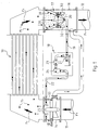
- FIG. 1 there is shown schematically, under the general reference 10, a heat exchanger, and, for example, a heat exchanger forming condenser, which, as shown by the arrows F1, is crossed by a flow coolant, in this case water, on the one hand, a inlet pipe 11, and, on the other hand, an outlet pipe 12.
- a flow coolant in this case water
- this is a tubular heat exchanger, which, by example, is of the type succinctly described in document FR-A-2 716,530 mentioned above.
- filtration means 13 are interposed on the inlet pipe 11, by means of a cuff 14.
- solid elements of cleaning 15 are likely to be permanently circulated in the heat exchanger 10, for continuous cleaning thereof.
- these solid cleaning elements 15 are systematically injected into the inlet pipe 11, downstream of the filtration means 13, to be driven by the incoming flow.
- the management installation 18 comprises a recycling line 19 connected, on one side, to a recuperator 20 to which the solid cleaning elements 15 are directed by the interception means 17 and, on the other side, to the suction of a pump 21 connected to a return 22 via a counter 23 and a collector 24;
- the return line 22 serves, in the sleeve 14, nozzles 25 which inject solid cleaning elements into the incoming flow 15 to recirculate in it and which preferably are oriented to against the current.
- the interception means 17 here consist of two grids 30 arranged in a V, the point of which is directed downwards, towards the recuperator 20 that it surrounds.
- Each grid 30 is rotatably mounted around an axis 31 so that, thanks to geared motors 32, they can occupy at least two positions, a so-called operational position, point of V downwards, as shown, and a so-called cleaning position, point of V upwards, as as sketched in dashed lines, in which the grids 30 can be cleared of unwanted elements that they would have retained and that would interfere the rolling of the solid cleaning elements 15 along the grids 30.
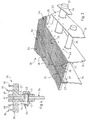
- a grid 30, better visible in FIGS. 2 to 4 comprises a frame 33 consisting of metal chevrons in the form of plates 34 arranged in parallel with a regular pitch and crossed by, and welded to, transverse spacers 35 and axis 31.
- grid elements 36 are assembled on this frame 33, of form generally rectangular, extending between two plates 34 and one after the other.
- Each grid element 36 is obtained by molding, preferably of a synthetic material, such as for example polypropylene, polyphenylene, or other synthetic material.
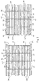
- a grid element 36 has a generally U-shaped cross section, with two wings 37; the soul of the U is defined by a plurality of bars 38 longitudinal connected by transverse cross-pieces 39 of lesser height, the bars 38 and the sleepers 39 defining a plurality of meshes 40 here rectangular.
- the wings 37 are provided with an external longitudinal edge 41, extending along the entire length of the grid element 36, by which it rests on the edge of the plate 34, as visible in FIG. 4, the distance transverse of the outer faces of the wings 37 being equal to that which separates the internal faces opposite two neighboring plates 34 between which is arranged the grid element 36.
- the wings 37 grid elements 36 are provided with holes 42, advantageously oblong in the longitudinal direction of the grid elements 36; the holes 42 come to the holes 43 formed in the plates 34.
- Bolts 44 assemble to plate 34, Figure 4, through holes 42 and at the holes 43, the grid elements 36 placed on either side of the latter.
- Positioning means are provided for positioning precise relative of the grid elements 36, with respect to each other.
- These positioning means comprise, at one end of the grid element 36, longitudinal tongues 45 placed laterally in end of the wings 37 and intended to cooperate with longitudinal notches 46 placed laterally at the other end of the grid element 36.
- these positioning means also comprise, between the longitudinal tabs 45, a projection 47 and a withdrawal 48 arranged transversely and intended to cooperate respectively with a withdrawal 48 and a projection 47 placed transversely between the longitudinal notches 46.
- the molding of the grid elements 36 can be produced with great precision and optimized to reduce pressure losses and turbulence which minimizes vibrations; the grid according to the invention is insensitive to corrosion, easily assembled, and light; its cost price is not high and can be changed easily, item by item.
- a grid according to the invention can be used for any level of any management facility, including a installation of the kind described in document FR-A-2 766 915.
Abstract
Description
La présente invention concerne d'une manière générale les échangeurs de chaleur, et, par exemple, les échangeurs de chaleur tubulaires formant condenseurs, dont le nettoyage est assuré en continu par des éléments solides, en pratique en forme de boule et réalisés par exemple en caoutchouc mousse, mis systématiquement en circulation à cet effet dans l'un des flux concernés.The present invention relates generally to exchangers heat, and, for example, tubular heat exchangers forming condensers, which are continuously cleaned by solid elements, in practice in the form of a ball and made for example of foam rubber, systematically put into circulation for this purpose in one of the flows concerned.
Dans leur principe, les dispositions correspondantes sont connues de longue date, notamment par les documents US-A-1 795 348 et DE-A-23 14 329.In principle, the corresponding provisions are known from long-standing, in particular by documents US-A-1,795,348 and DE-A-23 14,329.
Comme on le sait, les tubes d'échangeurs parcourus par de l'eau prélevée dans le milieu naturel, recyclée ou non, tendent à s'encrasser. L'encrassement se fait sous la forme soit d'un film biologique de surface, soit de dépôts de particules fines, soit par entartrage, et le plus souvent par combinaison de ces différents effets.As is known, the exchanger tubes traversed by withdrawn water in the natural environment, recycled or not, tend to clog. The fouling made either as a surface biological film or as a deposit of particles fine, either by scaling, and most often by combination of these different effects.
Le nettoyage des tubes est obtenu en injectant en amont de l'échangeur des éléments solides de nettoyage, généralement des boules de caoutchouc mousse de densité sensiblement égale à celle de l'eau de refroidissement et de diamètre très légèrement supérieur au diamètre interne des tubes à nettoyer.The tubes are cleaned by injecting upstream of the exchanger solid cleaning items, usually rubber balls foam of density substantially equal to that of cooling water and diameter very slightly greater than the internal diameter of the tubes to be cleaned.
Ces éléments solides de nettoyage sont captés dans la tuyauterie de sortie de l'échangeur par interposition d'une grille à barreaux inclinée, par exemple de 20 à 30°, de forme elliptique ; les éléments interceptés roulent le long de la grille sous l'effet du courant d'eau et sont collectés à l'extrémité aval de la grille.These solid cleaning elements are captured in the piping of outlet of the exchanger by interposing an inclined bar grid, by example from 20 to 30 °, elliptical in shape; the intercepted elements roll the along the grid under the effect of the water current and are collected at the downstream end of the grid.
Pour limiter la longueur du dispositif, on utilise souvent deux grilles en V, pointe en haut ou pointe en bas, avec collecte des éléments de nettoyage des deux côtés ou au centre, respectivement.To limit the length of the device, two V-shaped grids are often used, point up or point down, with collection of cleaning elements for two sides or in the center, respectively.
Les éléments sont extraits avec une faible partie du débit d'eau par une pompe ; plus généralement, la gestion des éléments solides de nettoyage conduit, grâce à un sas de collecte, ou à les arrêter, ou à les laisser circuler ou à les changer ; pour leur recyclage, la pompe les renvoie, ainsi que l'eau, à l'amont de l'échangeur. The elements are extracted with a small part of the water flow by a pump ; more generally, the management of solid cleaning elements leads, through a collection airlock, or to stop them, or to let them circulate or change them; for recycling, the pump returns them, as well as the water, upstream of the exchanger.
Les grilles sont constituées d'un châssis support généralement articulé pour permettre le pivotement des grilles et leur nettoyage périodique par contre courant.The grids consist of a generally articulated support frame to allow the pivoting of the grids and their periodic cleaning on the other hand current.
Le châssis supporte les grilles constituées de barreaux équidistants offrant des espaces libres de quelques millimètres entre elles.The chassis supports the grids made up of equidistant bars offering free spaces of a few millimeters between them.
Les éléments de nettoyage qui sont, par leur nature, déformables imposent que les grilles soient d'une qualité très grande : écart constant entre les barreaux, absence d'aspérités, de discontinuités, de points singuliers afin d'éviter tout arrêt des éléments et leur accumulation, ce qui les rendrait inopérants.Cleaning elements which are by their nature deformable require that the grids be of very high quality: constant gap between the bars, lack of roughness, discontinuities, singular points to avoid any shutdown of the elements and their accumulation, which would make them inoperative.
Par ailleurs, les barreaux doivent être minces afin de réduire la perte de charge.In addition, the bars must be thin in order to reduce the loss of charge.
L'écoulement de l'eau à vitesse assez élevée, de l'ordre de 1,5 à 3 m/sec généralement, dans la tuyauterie tend à engendrer des vibrations potentiellement destructrices des matériaux par la fatigue qu'elles engendrent.The flow of water at fairly high speed, of the order of 1.5 to 3 m / sec generally in the piping tends to generate vibrations potentially destructive of materials by the fatigue they generate.
La méthode actuelle de construction des grilles consiste à percer des trous dans les barreaux métalliques, en acier inox, à intervalles réguliers et à les assembler par des tirants enfilés dans les trous avec interposition d'entretoises tubulaires entre les barreaux ; ces opérations sont longues et coûteuses ; par ailleurs, la longévité de telles grilles dépend de la qualité du serrage, de la tenue des entretoises, de l'espacement des tirants ; de plus, des réparations en place dans le tuyau ou la manchette où elles sont montées sont très difficiles.The current method of constructing grids is to drill holes holes in the metal bars, in stainless steel, at regular intervals and at assemble by tie rods threaded in the holes with interposition of spacers tubular between the bars; these operations are long and costly; through elsewhere, the longevity of such grids depends on the quality of the tightening, the holding spacers, spacing of tie rods; in addition, repairs in place in the pipe or the cuff where they are mounted are very difficult.
En cas de léger desserrage, les mouvements relatifs des éléments l'accentuent par l'usure due aux frottements des constituants de la grille entre eux et accélère sa ruine. L'eau stagnante emprisonnée entre bagues et tirants, bagues et barreaux et autres, favorise la corrosion de l'acier inoxydable.In the event of slight loosening, the relative movements of the elements accentuate it by the wear due to the friction of the components of the grid between them and accelerates its ruin. Stagnant water trapped between rings and tie rods, rings and bars and others, promotes corrosion of stainless steel.
En variante, on a proposé de souder les barreaux sur des barrettes support ; de telles soudures sont très nombreuses et très petites, et vulnérables à la corrosion ; elles engendrent des tensions internes dans le métal et réduisent la résistance à la fatigue vibratoire ; la tenue dans le temps de telles grilles est limitée.As a variant, it has been proposed to weld the bars on bars support; such welds are very numerous and very small, and vulnerable corrosion; they generate internal stresses in the metal and reduce resistance to vibration fatigue; the durability of such grids is limited.
La présente invention a pour but de pallier à ces inconvénients.The present invention aims to overcome these drawbacks.
Suivant des dispositions qui peuvent par exemple être du type de celles décrites dans le document FR-A-2 716 530, une gestion des éléments solides de nettoyage implique, fondamentalement, d'une part, pour éviter que, avec le flux qui les véhicule, les éléments solides de nettoyage en cause soient évacués à l'égout, l'interposition, sur la canalisation de sortie de l'échangeur de chaleur, de moyens d'interception propres à leur retenue, et, d'autre part, le recyclage, vers la canalisation d'entrée de l'échangeur de chaleur, des éléments solides de nettoyage ainsi retenus par ces moyens d'interception.According to provisions which can for example be of the type of those described in document FR-A-2 716 530, a management of solid elements cleaning basically involves, on the one hand, to avoid that, with the flow that carries them, the solid cleaning elements involved are evacuated to the sewer, the interposition, on the outlet pipe of the heat exchanger heat, means of interception specific to their containment, and, on the other hand, the recycling, to the inlet pipe of the heat exchanger, solid cleaning elements thus retained by these means of interception.
Dans la pratique, il est également courant de faire passer systématiquement les éléments solides de nettoyage à travers un dispositif de gestion propre, notamment, à en contrôler le nombre, à trier, et à éliminer, ceux dont les dimensions sont devenues, par usure, inférieures à celles requises, et à permettre, en conséquence, un réapprovisionnement de l'ensemble en éléments solides de nettoyage neufs.In practice, it is also common to pass systematically the solid elements of cleaning through a device of own management, in particular, to control the number, to sort, and to eliminate, those whose dimensions have become, by wear, smaller than those required, and to allow, accordingly, a replenishment of the set of new solid cleaning elements.
La présente invention a pour but de proposer des moyens dits d'interception en forme de grille qui ne présentent pas les inconvénients de ceux de l'art antérieur et qui peuvent intervenir à tout niveau d'une installation de gestion.The object of the present invention is to propose so-called means intercept in the form of a grid which does not have the disadvantages of those of the prior art and which can intervene at any level of an installation Management.
Selon l'invention, une grille pour intercepter des éléments solides mis en circulation dans un échangeur de chaleur pour le nettoyage de celui-ci, est caractérisée par le fait qu'elle comprend un châssis et, assemblés sur ce châssis, des éléments de grille obtenus par moulage.According to the invention, a grid for intercepting solid elements placed circulation in a heat exchanger for cleaning thereof, is characterized by the fact that it comprises a chassis and, assembled on this chassis, grid elements obtained by molding.
Avantageusement, les éléments de grille sont obtenus par moulage d'une matière synthétique ; la matière synthétique est un polypropylène ; la matière synthétique est un polyphenylène.Advantageously, the grid elements are obtained by molding a synthetic material; the synthetic material is polypropylene; matter synthetic is a polyphenylene.
De préférence, le châssis est constitué de chevrons métalliques en forme de plaques disposées parallèlement selon un pas régulier et traversées par, et soudées à, des entretoises transversales et un axe d'articulation ; les éléments de grille sont de forme globalement rectangulaire et s'étendent entre deux plaques, à la suite l'un de l'autre.Preferably, the frame consists of metal rafters in the shape of plates arranged in parallel at a regular pitch and crossed by, and welded to, transverse spacers and a hinge pin; the elements of grid are of generally rectangular shape and extend between two plates, following one another.
Avantageusement, chaque élément de grille a une section transversale globalement en forme de U, avec deux ailes et une âme, ladite âme étant définie par une pluralité de barreaux longitudinaux reliés par des traverses transversales, les barreaux et les traverses définissant une pluralité de mailles. Advantageously, each grid element has a cross section generally U-shaped, with two wings and a core, said core being defined by a plurality of longitudinal bars connected by transverse crosspieces, the bars and the crossbeams defining a plurality of meshes.
De préférence, les ailes sont munies d'un rebord longitudinal externe par lequel l'élément de grille repose sur la tranche d'une plaque, la distance transversale des faces externes des ailes étant égale à celle qui sépare les faces internes en regard de deux plaques voisines entre lesquelles est disposé l'élément de grille.Preferably, the wings are provided with an external longitudinal edge by which the grid element rests on the edge of a plate, the distance transverse of the outer faces of the wings being equal to that which separates the faces internal facing two adjacent plates between which the element is disposed grid.
Avantageusement, les ailes des éléments de grille sont munies de trous destinés à venir au droit de perçages ménagés dans les plaques ; des boulons assemblent à une plaque les éléments de grille placés de part et d'autre de celle-ci.Advantageously, the wings of the grid elements are provided with holes. intended to come to the right of holes made in the plates; bolts assemble the grid elements placed on either side thereof to a plate.
De préférence, des moyens de positionnement sont prévus pour le positionnement relatif précis d'un élément de grille par rapport à un autre.Preferably, positioning means are provided for the precise relative positioning of one grid element with respect to another.
Avantageusement, les moyens de positionnement comprennent, à une extrémité de l'élément de grille, des languettes longitudinales placées latéralement en bout des ailes et destinées à coopérer avec des échancrures longitudinales placées latéralement à l'autre extrémité de l'élément de grille voisin.Advantageously, the positioning means comprise, at a end of the grid element, longitudinal tabs placed laterally at the end of the wings and intended to cooperate with longitudinal notches placed laterally at the other end of the neighboring grid element.
Indépendamment ou en combinaison avec les précédents, les moyens de positionnement comprennent, à une extrémité de l'élément de grille, une avancée et un retrait disposés transversalement et destinés à coopérer respectivement avec un retrait et une avancée disposés transversalement à l'autre extrémité de l'élément de grille voisin.Independently or in combination with the previous ones, the means of positioning include, at one end of the grid element, an advanced and a recess arranged transversely and intended to cooperate respectively with a recess and a projection arranged transversely at the other end of the neighboring grid element.
La présente invention a également pour objet une installation de gestion pour éléments solides de nettoyage circulant dans un échangeur de chaleur pour le nettoyage de celui-ci, du genre comportant des moyens d'interception propre à la retenue et/ou au guidage des éléments solides de nettoyage, caractérisée par le fait que les moyens d'interception comprennent au moins une grille telle que ci-dessus.The present invention also relates to a management installation. for solid cleaning elements circulating in a heat exchanger for the cleaning thereof, of the kind comprising means of interception specific to the retaining and / or guiding the solid cleaning elements, characterized by fact that the interception means comprise at least one grid as above.
Les caractéristiques et avantages de l'invention ressortiront d'ailleurs de
la description qui va suivre, à titre d'exemple, en référence aux dessins
schématiques annexés sur lesquels :
Sur la figure 1 on a schématisé, sous la référence générale 10, un
échangeur de chaleur, et, par exemple, un échangeur de chaleur formant
condenseur, qui, tel que schématisé par les flèches F1, est traversé par un flux
de fluide de refroidissement, en l'espèce de l'eau, à la faveur, d'une part, d'une
canalisation d'entrée 11, et, d'autre part, d'une canalisation de sortie 12.In Figure 1 there is shown schematically, under the
Un tel échangeur de chaleur 10 étant bien connu par lui-même, et ne
relevant pas, en propre, de la présente invention, il ne sera pas décrit ici.Such a
Il s'agit, en pratique, d'un échangeur de chaleur tubulaire, qui, par exemple, est du type de celui succinctement décrit dans le document FR-A-2 716 530 mentionné ci-dessus.In practice, this is a tubular heat exchanger, which, by example, is of the type succinctly described in document FR-A-2 716,530 mentioned above.
Dans la forme de mise en oeuvre représentée, des moyens de filtration
13 sont interposés sur la canalisation d'entrée 11, à la faveur d'une manchette
14.In the embodiment shown, filtration means
13 are interposed on the
Ces moyens de filtration 13, qui ne sont pas impératifs, ne relevant pas non plus de la présente invention, ils ne seront pas non plus décrits ici.These filtration means 13, which are not imperative, do not fall under neither of the present invention, they will not be described here either.
Il s'agit par exemple de moyens de filtration du type de ceux décrits dans le document FR-A-2 609 644.These are, for example, filtration means of the type described in document FR-A-2 609 644.
De manière connue en soi, également, des éléments solides de
nettoyage 15 sont susceptibles d'être mis en circulation permanente dans
l'échangeur de chaleur 10, pour le nettoyage en continu de celui-ci.In a manner known per se, also, solid elements of
cleaning 15 are likely to be permanently circulated in
the
Il s'agit, en pratique, de boules en caoutchouc mousse, dont le diamètre
est légèrement supérieur à celui des tubes de l'échangeur de chaleur 10, et
dont la densité, à l'état imprégné, est similaire à celle de l'eau.In practice, these are foam rubber balls, the diameter of which
is slightly higher than that of the tubes of the
Il convient d'assurer une gestion de ces éléments solides de nettoyage
15, c'est-à-dire non seulement d'en assurer une circulation effective dans
l'échangeur de chaleur 10, mais également, d'en contrôler le nombre et les
dimensions. These solid cleaning elements must be managed
15, that is to say not only to ensure its effective circulation in
the
De manière connue en soi, ces éléments solides de nettoyage 15 sont
systématiquement injectés dans la canalisation d'entrée 11, en aval des
moyens de filtration 13, pour être entraínés par le flux entrant.In a manner known per se, these
De manière connue en soi, également, on interpose, corollairement, sur
la canalisation de sortie 12, à la faveur d'une manchette 16, des moyens
d'interception 17 propres à la retenue des éléments solides de nettoyage 15 en
circulation, et, par une installation de gestion 18, on recycle, vers la
canalisation d'entrée 11, les éléments solides de nettoyage 15 retenus par ces
moyens d'interception 17.In a manner known per se, also, we interpose, as a corollary, on
the
De manière connue en soi, l'installation de gestion 18 comprend une
conduite de recyclage 19 reliée, d'un côté, à un récupérateur 20 vers lequel
sont dirigés les éléments solides de nettoyage 15 par les moyens d'interception
17 et, de l'autre côté, à l'aspiration d'une pompe 21 reliée à une conduite de
retour 22 par l'intermédiaire d'un compteur 23 et d'un collecteur 24 ; la
conduite de retour 22 dessert, dans la manchette 14, des tuyères 25 qui
assurent l'injection, dans le flux entrant, des éléments solides de nettoyage 15
à remettre en circulation dans celui-ci et qui préférentiellement sont orientées à
contre-courant.In a manner known per se, the
Les moyens d'interception 17 sont constitués ici de deux grilles 30
disposées en V dont la pointe est dirigée vers le bas, vers le récupérateur 20
qu'elle entoure.The interception means 17 here consist of two
Chaque grille 30 est montée à rotation autour d'un axe 31 en sorte que,
grâce à des moto-réducteurs 32, elles peuvent occuper au moins deux
positions, une position dite opérationnelle, pointe du V vers le bas, comme
représenté, et une position dite de nettoyage, pointe du V vers le haut, tel
qu'esquissé en traits mixtes, dans laquelle les grilles 30 peuvent être
débarrassées d'éléments indésirables qu'elles auraient retenus et qui gêneraient
le roulement des éléments solides de nettoyage 15 le long des grilles 30.Each
Une grille 30, mieux visible sur les figures 2 à 4, comprend un châssis
33 constitué de chevrons métalliques en forme de plaques 34 disposées
parallèlement selon un pas régulier et traversées par, et soudées à, des
entretoises transversales 35 et l'axe 31. A
Sur ce châssis 33, sont assemblés des éléments de grille 36, de forme
globalement rectangulaire, s'étendant entre deux plaques 34 et à la suite l'un
de l'autre.On this
Chaque élément de grille 36 est obtenu par moulage, de préférence d'un
matériau synthétique, tel que par exemple du polypropylène, du polyphénylène,
ou autre matériau synthétique.Each
Un élément de grille 36 a une section transversale globalement en U,
avec deux ailes 37 ; l'âme du U est définie par une pluralité de barreaux 38
longitudinaux reliés par des traverses 39 transversales de moindre hauteur, les
barreaux 38 et les traverses 39 définissant une pluralité de mailles 40 ici
rectangulaires.A
Les ailes 37 sont munies d'un rebord longitudinal externe 41, s'étendant
selon toute la longueur de l'élément de grille 36, par lequel celui-ci repose sur
la tranche de la plaque 34, comme visible sur la figure 4, la distance
transversale des faces externes des ailes 37 étant égale à celle qui sépare les
faces internes en regard de deux plaques 34 voisines entre lesquelles est
disposé l'élément de grille 36.The
Pour la fixation des éléments de grille 36 sur le châssis 33, les ailes 37
des éléments de grille 36 sont munies de trous 42, avantageusement oblongs
dans la direction longitudinale des éléments de grille 36 ; les trous 42
viennent au droit de perçages 43 ménagés dans les plaques 34.For fixing the
Des boulons 44 assemblent à la plaque 34, figure 4, grâce aux trous 42
et aux perçages 43, les éléments de grille 36 placés de part et d'autre de celle-ci.
Des moyens de positionnement sont prévus pour le positionnement
relatif précis des éléments de grille 36, les uns par rapport aux autres.Positioning means are provided for positioning
precise relative of the
Ces moyens de positionnement comprennent, à une extrémité de
l'élément de grille 36, des languettes longitudinales 45 placées latéralement en
bout des ailes 37 et destinées à coopérer avec des échancrures longitudinales
46 placées latéralement à l'autre extrémité de l'élément de grille 36. These positioning means comprise, at one end of
the
Ici, ces moyens de positionnement comprennent également, entre les
languettes longitudinales 45, une avancée 47 et un retrait 48 disposés
transversalement et destinés à coopérer respectivement avec un retrait 48 et
une avancée 47 placés transversalement entre les échancrures longitudinales
46.Here, these positioning means also comprise, between the
Grâce au moulage des éléments de grille 36, ceux-ci peuvent être
réalisés avec une grande précision et optimisés pour réduire pertes de charge
et turbulences ce qui minimise les vibrations ; la grille selon l'invention est
insensible à la corrosion, facilement assemblée, et légère ; son prix de revient
n'est pas élevé et elle peut être changée facilement, élément par élément.Thanks to the molding of the
Comme on l'aura compris, une grille selon l'invention peut être utilisée à n'importe quel niveau d'une installation de gestion quelconque, y compris une installation du genre de celle décrite dans le document FR-A-2 766 915.As will be understood, a grid according to the invention can be used for any level of any management facility, including a installation of the kind described in document FR-A-2 766 915.
Claims (14)
Applications Claiming Priority (2)
| Application Number | Priority Date | Filing Date | Title |
|---|---|---|---|
| FR0008625 | 2000-07-03 | ||
| FR0008625A FR2811072B1 (en) | 2000-07-03 | 2000-07-03 | GRID FOR INTERCEPTING SOLID ELEMENTS CIRCULATED IN A HEAT EXCHANGER FOR CLEANING THE SAME, AND INSTALLATION FOR MANAGING SUCH ELEMENTS COMPRISING SUCH A GRID |
Publications (2)
| Publication Number | Publication Date |
|---|---|
| EP1170566A2 true EP1170566A2 (en) | 2002-01-09 |
| EP1170566A3 EP1170566A3 (en) | 2002-06-26 |
Family
ID=8852047
Family Applications (1)
| Application Number | Title | Priority Date | Filing Date |
|---|---|---|---|
| EP01401627A Withdrawn EP1170566A3 (en) | 2000-07-03 | 2001-06-20 | Grid for intercepting solid particles circulating in a heat exchanger for cleaning, and control device for such particles using such a grid |
Country Status (4)
| Country | Link |
|---|---|
| US (1) | US6609559B2 (en) |
| EP (1) | EP1170566A3 (en) |
| JP (1) | JP2002054893A (en) |
| FR (1) | FR2811072B1 (en) |
Families Citing this family (7)
| Publication number | Priority date | Publication date | Assignee | Title |
|---|---|---|---|---|
| DE10358858A1 (en) * | 2003-12-16 | 2005-07-14 | Robert Bosch Gmbh | Method and device for operating an inductive load with different electrical voltages |
| US6913071B1 (en) * | 2004-05-03 | 2005-07-05 | C.Q.M. Ltd. | Ball trap with safety-release gate |
| FR2892185B1 (en) * | 2005-10-19 | 2008-12-26 | Technos Et Cie Snc | FILTERING ELEMENT FOR A FILTRATION GRID FOR SEPARATING FROM A CARRIER FLUID CLEANING BODIES FROM A HEAT EXCHANGER. |
| FR2892186B1 (en) * | 2005-10-19 | 2008-02-08 | Technos Et Cie Snc | SEPARATING GRID FOR SEPARATING FROM A CARRIER FLUID CLEANING BODIES FROM A HEAT EXCHANGER. |
| KR100791243B1 (en) * | 2006-11-17 | 2008-01-03 | 한국에너지기술연구원 | Self-cleaning heat exchanger using solid particle-water supply system |
| JP2010169335A (en) * | 2009-01-23 | 2010-08-05 | Hitachi Ltd | Heat exchanger and water chamber for the same |
| WO2014046510A1 (en) * | 2012-09-20 | 2014-03-27 | 정우산기 주식회사 | Apparatus for recycling balls |
Citations (5)
| Publication number | Priority date | Publication date | Assignee | Title |
|---|---|---|---|---|
| DE3015677A1 (en) * | 1979-04-23 | 1980-11-06 | Hitachi Ltd | DEVICE FOR RECEIVING CLEANING BODIES USED FOR CLEANING A TUBE HEAT EXCHANGER |
| US4762610A (en) * | 1985-10-21 | 1988-08-09 | Screenex Wire Weaving Manufacturers (Proprietary) Limited | Screening arrangement |
| GB2203061A (en) * | 1987-04-10 | 1988-10-12 | Thule United Ltd | Filter screen assembly |
| US4960510A (en) * | 1987-06-26 | 1990-10-02 | Steinhaus Gmbh | Screening apparatus having a screen grid with a plurality of exchangeable screen elements |
| EP0457238A1 (en) * | 1990-05-14 | 1991-11-21 | Hitachi, Ltd. | Apparatus for collecting cleaning bodies for tubular heat exchanger |
Family Cites Families (13)
| Publication number | Priority date | Publication date | Assignee | Title |
|---|---|---|---|---|
| US1795348A (en) | 1927-03-30 | 1931-03-10 | Westinghouse Electric & Mfg Co | Condenser-cleaning system |
| JPS5111253B2 (en) | 1972-03-24 | 1976-04-09 | ||
| ZA774472B (en) * | 1977-07-25 | 1979-06-27 | Herrmann Screens Mfg Co Ltd | Improvements in or relating to screening apparatus |
| DE3390381C2 (en) * | 1982-12-09 | 1992-09-03 | Fioris Pty Ltd | Screening device comprising a plurality of screen elements |
| FR2609644B1 (en) | 1987-01-16 | 1991-01-04 | Beaudrey & Cie | SELF-CLEANING FILTER TO INSERT ON A PRESSURE PIPE |
| US4909929A (en) * | 1988-10-24 | 1990-03-20 | Norris Screen & Manufacturing, Inc. | Interlocking clamping system |
| IL94289A (en) * | 1990-05-04 | 1992-12-01 | Balls Technics Ltd | Cleaning system for cleaning fluid-conducting tubing |
| US5248043A (en) * | 1992-02-28 | 1993-09-28 | Dorn Lloyd A | Modular retro-fit screen system for a screening deck |
| FR2716530B1 (en) * | 1994-02-24 | 1996-07-12 | Beaudrey & Cie | Interception device for solid elements circulating in a heat exchanger for cleaning the latter. |
| FR2766915B1 (en) | 1997-07-31 | 1999-10-08 | Beaudrey & Cie | METHOD FOR THE MANAGEMENT OF SOLID ELEMENTS CIRCULATED IN A HEAT EXCHANGER FOR CLEANING THE SAME, AND CORRESPONDING INSTALLATION |
| FR2789598B1 (en) * | 1999-02-11 | 2001-04-27 | Beaudrey & Cie | MECHANICAL SIEVE, IN PARTICULAR FILTER APRON OF A CHAIN FILTER |
| US6283303B1 (en) * | 1999-03-29 | 2001-09-04 | M-I L.L.C. | Vibrating screen separator, separating method, and clamping device |
| US6267246B1 (en) * | 2000-02-14 | 2001-07-31 | Western Wire Works, Inc. | Screening system for screening or diverting particulate material |
-
2000
- 2000-07-03 FR FR0008625A patent/FR2811072B1/en not_active Expired - Fee Related
-
2001
- 2001-06-20 EP EP01401627A patent/EP1170566A3/en not_active Withdrawn
- 2001-07-03 JP JP2001201967A patent/JP2002054893A/en active Pending
- 2001-07-03 US US09/897,442 patent/US6609559B2/en not_active Expired - Lifetime
Patent Citations (5)
| Publication number | Priority date | Publication date | Assignee | Title |
|---|---|---|---|---|
| DE3015677A1 (en) * | 1979-04-23 | 1980-11-06 | Hitachi Ltd | DEVICE FOR RECEIVING CLEANING BODIES USED FOR CLEANING A TUBE HEAT EXCHANGER |
| US4762610A (en) * | 1985-10-21 | 1988-08-09 | Screenex Wire Weaving Manufacturers (Proprietary) Limited | Screening arrangement |
| GB2203061A (en) * | 1987-04-10 | 1988-10-12 | Thule United Ltd | Filter screen assembly |
| US4960510A (en) * | 1987-06-26 | 1990-10-02 | Steinhaus Gmbh | Screening apparatus having a screen grid with a plurality of exchangeable screen elements |
| EP0457238A1 (en) * | 1990-05-14 | 1991-11-21 | Hitachi, Ltd. | Apparatus for collecting cleaning bodies for tubular heat exchanger |
Also Published As
| Publication number | Publication date |
|---|---|
| US20020017379A1 (en) | 2002-02-14 |
| FR2811072A1 (en) | 2002-01-04 |
| EP1170566A3 (en) | 2002-06-26 |
| US6609559B2 (en) | 2003-08-26 |
| FR2811072B1 (en) | 2002-10-18 |
| JP2002054893A (en) | 2002-02-20 |
Similar Documents
| Publication | Publication Date | Title |
|---|---|---|
| EP1170566A2 (en) | Grid for intercepting solid particles circulating in a heat exchanger for cleaning, and control device for such particles using such a grid | |
| FR2524826A1 (en) | DEVICE FOR WASHING ROTARY SIEVES FOR WATER INLET OF INDUSTRIAL PLANTS | |
| FR3038041A1 (en) | SYSTEM FOR INTERCEPTING AND COLLECTING ALTERNATIVE SCAN CLEANING BODIES | |
| EP0694154B1 (en) | Device for recovering solid cleaning materials circulating through a heat exchanger | |
| EP3847408B1 (en) | Flexible heat exchanger intended to be positioned in a moving exterior fluid, comprising a collection of flexible temperature probes | |
| FR2503577A1 (en) | MOBILE FILTERING APRON FILTER | |
| EP2561301A2 (en) | System for extracting heat from an effluent flowing in a duct | |
| FR2594044A1 (en) | SELF-CLEANING FILTER. | |
| WO2009016102A1 (en) | Heat exchanger for gas, particularly for the exhaust gases of an engine | |
| EP0515286B1 (en) | Protection apparatus against clogging of plate-like heat-exchangers | |
| EP0679854B1 (en) | System for cleaning tubes by means of elastic balls | |
| EP1333903A1 (en) | Screening grid for separating cleaning particles from a fluid and device comprising same | |
| EP0012782A1 (en) | Cooling tower | |
| BE660070A (en) | ||
| FR2975305A1 (en) | Device, useful for retaining objects e.g. tree trunk in a liquid stream at an entrance of a hydraulic structure, comprises a plane plate having perforations, which are oblong, oval, rectangular or trapezoidal shaped | |
| FR2522644A3 (en) | CLINKER COOLING GRILL FOR CEMENT MANUFACTURING | |
| WO2005066573A1 (en) | Heat exchanger comprising cleaning means | |
| EP0223893B1 (en) | Self-cleaning filter and raked bar screen for canals and industrial applications | |
| FR2823560A1 (en) | SOLID ELEMENT MANAGEMENT SYSTEM CIRCULATED IN A HEAT EXCHANGER FOR CLEANING THE SAME INCLUDING A SORTER AND SORTER FOR SUCH A MANAGEMENT INSTALLATION | |
| EP1102956B1 (en) | Method and installation for managing solid elements circulating in a heat exchanger for cleaning the latter | |
| JP3001177B2 (en) | Dust prevention device at intake using multiple rotating disk type screen | |
| FR2909111A1 (en) | Floating debris e.g. algae, deflecting device, has water course creating units for creating water course in surface of river and in upstream of water sampling structure, where water course removes debris from water sampling structure | |
| JP2987266B2 (en) | Disc screen | |
| FR2766915A1 (en) | Installation for solid cleaner flowing in heat exchanger | |
| EP1777481B1 (en) | Separation grid for separating cleaning particles from a carrier fluid of a heat exchanger |
Legal Events
| Date | Code | Title | Description |
|---|---|---|---|
| PUAI | Public reference made under article 153(3) epc to a published international application that has entered the european phase |
Free format text: ORIGINAL CODE: 0009012 |
|
| AK | Designated contracting states |
Kind code of ref document: A2 Designated state(s): AT BE CH CY DE DK ES FI FR GB GR IE IT LI LU MC NL PT SE TR |
|
| AX | Request for extension of the european patent |
Free format text: AL;LT;LV;MK;RO;SI |
|
| PUAL | Search report despatched |
Free format text: ORIGINAL CODE: 0009013 |
|
| AK | Designated contracting states |
Kind code of ref document: A3 Designated state(s): AT BE CH CY DE DK ES FI FR GB GR IE IT LI LU MC NL PT SE TR |
|
| AX | Request for extension of the european patent |
Free format text: AL;LT;LV;MK;RO;SI |
|
| RIC1 | Information provided on ipc code assigned before grant |
Free format text: 7F 28G 1/12 A |
|
| 17P | Request for examination filed |
Effective date: 20021224 |
|
| AKX | Designation fees paid |
Designated state(s): AT BE CH CY DE DK ES FI FR GB GR IE IT LI LU MC NL PT SE TR |
|
| 17Q | First examination report despatched |
Effective date: 20030324 |
|
| STAA | Information on the status of an ep patent application or granted ep patent |
Free format text: STATUS: THE APPLICATION IS DEEMED TO BE WITHDRAWN |
|
| 18D | Application deemed to be withdrawn |
Effective date: 20031007 |