EP1170610A2 - Opto-electrical hybrid connector and process for assembling the same - Google Patents
Opto-electrical hybrid connector and process for assembling the same Download PDFInfo
- Publication number
- EP1170610A2 EP1170610A2 EP01116141A EP01116141A EP1170610A2 EP 1170610 A2 EP1170610 A2 EP 1170610A2 EP 01116141 A EP01116141 A EP 01116141A EP 01116141 A EP01116141 A EP 01116141A EP 1170610 A2 EP1170610 A2 EP 1170610A2
- Authority
- EP
- European Patent Office
- Prior art keywords
- optical element
- sleeve
- optical
- housing
- receiving cylinder
- Prior art date
- Legal status (The legal status is an assumption and is not a legal conclusion. Google has not performed a legal analysis and makes no representation as to the accuracy of the status listed.)
- Granted
Links
- 238000000034 method Methods 0.000 title claims abstract description 48
- 230000003287 optical effect Effects 0.000 claims abstract description 499
- 230000000994 depressogenic effect Effects 0.000 claims description 10
- 239000013307 optical fiber Substances 0.000 description 12
- 238000003780 insertion Methods 0.000 description 11
- 230000037431 insertion Effects 0.000 description 9
- 229920003002 synthetic resin Polymers 0.000 description 7
- 239000000057 synthetic resin Substances 0.000 description 7
- 238000009751 slip forming Methods 0.000 description 5
- 239000002184 metal Substances 0.000 description 4
- 229920000049 Carbon (fiber) Polymers 0.000 description 3
- 239000004917 carbon fiber Substances 0.000 description 3
- 230000006866 deterioration Effects 0.000 description 3
- 230000000712 assembly Effects 0.000 description 2
- 238000000429 assembly Methods 0.000 description 2
- 238000004049 embossing Methods 0.000 description 2
- 229920005989 resin Polymers 0.000 description 2
- 239000011347 resin Substances 0.000 description 2
- 238000005476 soldering Methods 0.000 description 2
- 230000007175 bidirectional communication Effects 0.000 description 1
- 239000003822 epoxy resin Substances 0.000 description 1
- 239000000835 fiber Substances 0.000 description 1
- 239000011521 glass Substances 0.000 description 1
- 239000004033 plastic Substances 0.000 description 1
- 229920000647 polyepoxide Polymers 0.000 description 1
Images


Classifications
-
- G—PHYSICS
- G02—OPTICS
- G02B—OPTICAL ELEMENTS, SYSTEMS OR APPARATUS
- G02B6/00—Light guides; Structural details of arrangements comprising light guides and other optical elements, e.g. couplings
- G02B6/24—Coupling light guides
- G02B6/42—Coupling light guides with opto-electronic elements
- G02B6/4201—Packages, e.g. shape, construction, internal or external details
- G02B6/4274—Electrical aspects
- G02B6/4277—Protection against electromagnetic interference [EMI], e.g. shielding means
-
- G—PHYSICS
- G02—OPTICS
- G02B—OPTICAL ELEMENTS, SYSTEMS OR APPARATUS
- G02B6/00—Light guides; Structural details of arrangements comprising light guides and other optical elements, e.g. couplings
- G02B6/24—Coupling light guides
- G02B6/36—Mechanical coupling means
- G02B6/38—Mechanical coupling means having fibre to fibre mating means
- G02B6/3807—Dismountable connectors, i.e. comprising plugs
- G02B6/381—Dismountable connectors, i.e. comprising plugs of the ferrule type, e.g. fibre ends embedded in ferrules, connecting a pair of fibres
- G02B6/3817—Dismountable connectors, i.e. comprising plugs of the ferrule type, e.g. fibre ends embedded in ferrules, connecting a pair of fibres containing optical and electrical conductors
-
- G—PHYSICS
- G02—OPTICS
- G02B—OPTICAL ELEMENTS, SYSTEMS OR APPARATUS
- G02B6/00—Light guides; Structural details of arrangements comprising light guides and other optical elements, e.g. couplings
- G02B6/24—Coupling light guides
- G02B6/36—Mechanical coupling means
- G02B6/38—Mechanical coupling means having fibre to fibre mating means
- G02B6/3807—Dismountable connectors, i.e. comprising plugs
- G02B6/3897—Connectors fixed to housings, casing, frames or circuit boards
-
- G—PHYSICS
- G02—OPTICS
- G02B—OPTICAL ELEMENTS, SYSTEMS OR APPARATUS
- G02B6/00—Light guides; Structural details of arrangements comprising light guides and other optical elements, e.g. couplings
- G02B6/24—Coupling light guides
- G02B6/42—Coupling light guides with opto-electronic elements
- G02B6/4201—Packages, e.g. shape, construction, internal or external details
- G02B6/4204—Packages, e.g. shape, construction, internal or external details the coupling comprising intermediate optical elements, e.g. lenses, holograms
- G02B6/421—Packages, e.g. shape, construction, internal or external details the coupling comprising intermediate optical elements, e.g. lenses, holograms the intermediate optical component consisting of a short length of fibre, e.g. fibre stub
-
- G—PHYSICS
- G02—OPTICS
- G02B—OPTICAL ELEMENTS, SYSTEMS OR APPARATUS
- G02B6/00—Light guides; Structural details of arrangements comprising light guides and other optical elements, e.g. couplings
- G02B6/24—Coupling light guides
- G02B6/42—Coupling light guides with opto-electronic elements
- G02B6/4201—Packages, e.g. shape, construction, internal or external details
- G02B6/4246—Bidirectionally operating package structures
-
- G—PHYSICS
- G02—OPTICS
- G02B—OPTICAL ELEMENTS, SYSTEMS OR APPARATUS
- G02B6/00—Light guides; Structural details of arrangements comprising light guides and other optical elements, e.g. couplings
- G02B6/24—Coupling light guides
- G02B6/42—Coupling light guides with opto-electronic elements
- G02B6/4292—Coupling light guides with opto-electronic elements the light guide being disconnectable from the opto-electronic element, e.g. mutually self aligning arrangements
- G02B6/4293—Coupling light guides with opto-electronic elements the light guide being disconnectable from the opto-electronic element, e.g. mutually self aligning arrangements hybrid electrical and optical connections for transmitting electrical and optical signals
-
- G—PHYSICS
- G02—OPTICS
- G02B—OPTICAL ELEMENTS, SYSTEMS OR APPARATUS
- G02B6/00—Light guides; Structural details of arrangements comprising light guides and other optical elements, e.g. couplings
- G02B6/24—Coupling light guides
- G02B6/42—Coupling light guides with opto-electronic elements
- G02B6/4201—Packages, e.g. shape, construction, internal or external details
- G02B6/4219—Mechanical fixtures for holding or positioning the elements relative to each other in the couplings; Alignment methods for the elements, e.g. measuring or observing methods especially used therefor
- G02B6/4228—Passive alignment, i.e. without a detection of the degree of coupling or the position of the elements
- G02B6/423—Passive alignment, i.e. without a detection of the degree of coupling or the position of the elements using guiding surfaces for the alignment
-
- G—PHYSICS
- G02—OPTICS
- G02B—OPTICAL ELEMENTS, SYSTEMS OR APPARATUS
- G02B6/00—Light guides; Structural details of arrangements comprising light guides and other optical elements, e.g. couplings
- G02B6/24—Coupling light guides
- G02B6/42—Coupling light guides with opto-electronic elements
- G02B6/4292—Coupling light guides with opto-electronic elements the light guide being disconnectable from the opto-electronic element, e.g. mutually self aligning arrangements
Definitions
- the present invention relates to a hybrid connector, in which electric and optical connectors are integrally formed, so that a simple connecting operation completes the connection between the electric and optical connectors, and to a process for assembling the hybrid connector.
- the hybrid connector is formed in such a way that the electric and optical connectors are integrally constituted therein, the hybrid connector is forced to have many components. Especially, the assembly of the optical connector is troublesome because it requires many man-hours. Furthermore, there has been a problem that optical element modules constituting the optical connector can not be stably positioned upon the assembly.
- the optical element modules can not be stably positioned upon the assembly, it affects the warkability of the assembling operation and sometimes affects the optical loss characteristic after the assembly.
- a first aspect of the present invention is to provide a process for assembling a male hybrid connector having electric and optical connectors formed integrally with each other, the optical connector including: at least one optical element module having an optical element; sleeves, each of which has an optical waveguide, provided in accordance with the number of the optical element modules; a housing shared with the electric connector, the housing having receiving cylinders for holding the sleeves therein; and a case for holding the optical element modules, the process comprising the steps of:
- the hybrid connector is assembled through a process including the first to third assembly steps. That is, the optical connector portion of the hybrid connector is assembled in the first to third assembly steps.
- the sleeve is provisionally halfway inserted into the receiving cylinder of the housing.
- the optical element module is pressed so as to insert the sleeve further into the receiving cylinder, thereby the sleeve is completely (fully) inserted into the receiving cylinder.
- the projection of the optical element module engages with the hollow portion of the housing side, thereby the position of the optical element is aligned with the axis of the receiving cylinder.
- the assembly of the sleeve and that of the optical element modules are carried out simultaneously, thereby the assembly operation is simplified.
- each projection of the optical element modules engages with the hollow portion of the receiving cylinder, thereby no clearance arises and each position of the optical element modules is stable thereafter. Therefore, the workability improves and the optical loss is reduced.
- the optical element module is pressed against the sleeve so that the sleeve is inserted into the receiving cylinder, thereby the optical loss due to the clearance between the sleeve and the optical element module is minimized.
- the case holds the optical element modules.
- the case engages with the receiving cylinders, then each position of the optical element modules is fixed. Since these assemblies are carried out simultaneously, the assembly operation is simplified. Since the position of the optical element module is stable, the workability for assembling the case is improved.
- a second aspect of the present invention is to provide a process for assembling a male hybrid connector having electric and optical connectors formed integrally with each other, the optical connector including: at least one optical element module having an optical element; sleeves, each of which has an optical waveguide, provided in accordance with the number of the optical element modules; a housing shared with the electric connector, the housing having receiving cylinders for holding the sleeves therein; and a case for holding the optical element modules, the process comprising the steps of:
- the hybrid connector is simply assembled.
- the position of the optical element module is stabilized so as to improve the workability and to reduce the optical loss.
- a third aspect of the present invention is to provide a process for assembling a male hybrid connector having electric and optical connectors formed integrally with each other, the optical connector including: at least one optical element module having an optical element; sleeves, each of which has an optical waveguide, provided in accordance with the number of the optical element modules; a housing shared with the electric connector, the housing having receiving cylinders for holding the sleeves therein; and a case for holding the optical element modules, the process comprising the steps of:
- the hybrid connector is simply assembled.
- the position of the optical element module is stabilized so as to improve the workability and to reduce the optical loss.
- the sleeve is inserted into the receiving cylinder until the sleeve comes into contact with first projections formed in the receiving cylinder for press-inserting the sleeve, and in the second, second modified or second further modified assembly step, the sleeve is press-inserted into the receiving cylinder crushing the first projections.
- the sleeve is smoothly inserted in the first assembly step, thereby the assembly operation can be simplified further.
- a moving length of the sleeve in the receiving cylinder in the second, second modified or second further modified assembly step is shorter than that in the first assembly step.
- the labor required for press-insertion of the sleeve is reduced, thereby the assembly operation can be simplified further.
- a fourth aspect of the present invention is to provide a process for assembling a male hybrid connector having electric and optical connectors formed integrally with each other, the optical connector including: at least one optical element module having an optical element; sleeves, each of which has an optical waveguide, provided in accordance with the number of the optical element modules; a housing shared with the electric connector, the housing having receiving cylinders for holding the sleeves therein; a sleeve holder to be inserted in the housing for holding the sleeves together with the receiving cylinders; and a case for holding the optical element modules, the process comprising the steps of:
- the hybrid connector is simply assembled.
- the position of the optical element module is stabilized so as to improve the workability and to reduce the optical loss.
- the optical loss due to the clearance between the sleeve and the optical element module is minimized.
- the end face of the sleeve is free from the fat of the human hand, thereby the deterioration in the transmitting efficiency due to the assembly is prevented from occurring.
- a fifth aspect of the present invention is to provide a process for assembling a male hybrid connector having electric and optical connectors formed integrally with each other, the optical connector including: at least one optical element module having an optical element; sleeves, each of which has an optical waveguide, provided in accordance with the number of the optical element modules; a housing shared with the electric connector, the housing having receiving cylinders for holding the sleeves therein; a sleeve holder to be inserted in the housing for holding the sleeves together with the receiving cylinders; and a case for holding the optical element modules, the process comprising the steps of:
- a sixth aspect of the present invention is to provide a process for assembling a male hybrid connector having electric and optical connectors formed integrally with each other, the optical connector including: at least one optical element module having an optical element; sleeves, each of which has an optical waveguide, provided in accordance with the number of the optical element modules; a housing shared with the electric connector, the housing having receiving cylinders for holding the sleeves therein; a sleeve holder to be inserted in the housing for holding the sleeves together with the receiving cylinders; and a case for holding the optical element modules, the process comprising the steps of:
- a seventh aspect of the present invention is to provide a male hybrid connector including electric and optical connectors formed integrally with each other, the optical connector comprising:
- the projection of the optical element module is formed so as to engage with the hollow portion of the housing side, thereby the position of the optical element can be aligned with the axis of the receiving cylinder.
- the engagement stablizes the position of the optical element module, thereby the workability improves and the optical loss is reduced.
- An eighth aspect of the present invention is to provide a male hybrid connector including electric and optical connectors formed integrally with each other, the optical connector comprising:
- the positional shift of the optical element modules due to the rotation thereof is prevented from occurring and each position of the optical element modules is stabilized. Therefore, the workability improves and the optical loss is reduced.
- a ninth aspect of the present invention is to provide a male hybrid connector including electric and optical connectors formed integrally with each other, the optical connector comprising:
- the position of the optical element module is stabilized, thereby the workability improves and the optical loss is reduced.
- a second wall which faces the first wall and holds the optical element modules between the first and second walls, is formed on the receiving cylinder.
- the optical element module is securely prevented from rotating, thereby the workability further improves and the optical loss is further reduced.
- a tenth aspect of the present invention is to provide a male hybrid connector including electric and optical connectors formed integrally with each other, the optical connector comprising:
- the position of the optical element module is stabilized so as to improve the workability and to reduce the optical loss.
- An eleventh aspect of the present invention is to provide a male hybrid connector including electric and optical connectors formed integrally with each other, the optical connector comprising:
- a twelfth aspect of the present invention is to provide a male hybrid connector including electric and optical connectors formed integrally with each other, the optical connector comprising:
- a second wall which faces the first wall and holds the optical element modules between the first and second walls, is formed on the receiving cylinder and/or the sleeve holder.
- Figure 1 is an exploded perspective view of a hybrid connector according to a preferred embodiment of the present invention.
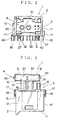
- Figure 2 is a front view of the hybrid connector;
- Figure 3 is a plan view of the hybrid connector;
- Figure 4 is a left side view of the hybrid connector;
- Figure 5 is a right side view of the housing.
- the hybrid connector is defined as a connector, in which electric and optical connectors are integrally formed.
- the reference numeral 1 denotes a male hybrid connector to be mounted on a print-circuit board, which is not shown in the figure.
- the hybrid connector 1 comprises an electric connector 3 and an opetical connetor 4, both of which share a housing 2.
- the hybrid connector according to the present invention is constructed so that the assembling operation thereof can be easily carried out and the optical element modules 8 and 9 can be stably positioned upon the assembly.
- the hybrid connector 1 is connected to a female hybrid connector 5, in which two optical fiber cables (optical fiber cords; not shown in the figure), on each end of which a corresponding ferrule is mounted, are mounted in parallel in a housing of the female hybrid connector 5. Out of the two optical fiber cables, one is for transmitting while the other is for receiving. On an end face of the ferrule, there is exposed a core portion ((plastic) optical fiber consisting of a core and a clad), an optical axis of which aligns with that of a respective optical waveguide 28 in a sleeve 7 explained later on.
- a core portion ((plastic) optical fiber consisting of a core and a clad)
- the electric connector 3 consists of the housing 2 and electric terminals (PCB terminals) 6.
- the optical connector 4 consists of the housing 2, the sleeves 7, optical element modules 8 and 9, and a shielding case 10.
- the optical element modules 8 and 9 of the optical connector 4 may be called a receiving/emission module, receiving/ transmitting module or a fiber optic transceiver (FOT).
- the shielding case 10 corresponds to the case described in the claims.
- the housing 2 made of an insulative synthetic resin is formed in a rectangular box shape, in which a flont face 11 is opened. That is, the housing 2 is formed in a rectangular box shape with an upper wall 12, bottom wall 13, right sidewall 14, left sidewall 15 and an inside wall 16.
- the upper wall 12 is provided with a lock portion, with which a locking arm formed on the hybrid connector 5 engaged.
- Each of the right sidewall 14 and the left sidewall 15 is provided with a corresponding pocket 17 for receiving a fixing pin 18 made of metal therein and engaging with the same.
- Each pocket 17 is provided with a through hole, which is opened at the print-circuit board side, and a part of the fixing pin 18 is fixed to the print-circuit board through the through hole.
- the inside wall 16 of the housing 2 is provided integrally with a pair of receiving cylinders 19, which is formed in a cylindrical shape so that the inner cross section thereof is round.
- the receiving cylinder 19 has a length in accordance with the length of the sleeve 7.
- the receiving cylinder 19 protrudes toward an engaging space 20 for engaging with the hybrid connector 5 in the housing 2 and is formed to also protrude toward the rear of the inside wall 16.
- the ferrules are inserted from the engaging space 20 side.
- the three first projections 21 are formed along the length direction of the receiving cylinder 19 with 120° pitch.
- a diameter of a circular arc drawn by the end of the three first projections 21 is formed a little smaller than the diameter of the sleeve 7 and the sleeve 7 inserted into the receiving cylinder 19 is press fit thereinto crushing the three first projections 21.
- the inner diameter of the receiving cylinder 19 is set up so that each sleeve 7 can be smoothly inserted thereinto until the sleeve 7 comes into contact with the three first projections 21.
- each receiving cylinder 19 On the outside end of each receiving cylinder 19 at the side from which the sleeve 7 is inserted, a corresponding engaging part 22 protruding with having a ring-shape is integrally formed with the receiving cylinder 19. On an end face of the outside end, there is formed a hollow portion 23 (see Fig. 6 or Fig. 15) depressed along the axis of the receiving cylinder 19. On the outside end of each receiving cylinder 19 at the side of the right sidewall 14 and the left sidewall 15, there is provided a step 24. In addition, at the bottom wall 13 side thereof, a leg 25 is continuously formed.
- the protruding direction of the engaging part 22 crosses at right angles with respect to the axis of the receiving cylinder 19 and the thickness of the engaging part 22 is formed to give an enough stiffness threreto so that it can resist against a force acting along the axis of the receiving cylinder 19.
- the shielding case 10 engages with the engaging parts 22.
- the diameter of the hollow 23 is larger than the inner diameter of the receiving cylinder 19.
- the hollow 23 engages with a second projection 35 (explained later on) of the optical element module 8 and 9.
- Each step 24 is formed along the axis of the receiving cylinder 19 and engages with a corresponding stopper 41 (explained later on) of the shielding case 10.
- the leg 25 is formed in a letter H-shape in a cross sectional view thereof and the portion, which protrudes rearward exceeding the end face of the end of the receiving cylinder 19, is provided with a wall 26, which crosses at right angles with respect to the end face.
- the wall 26 serves as a stopper to prevent the optical element modules 8 and 9 from rotating and is formed to have a flat surface in the present preferred embodiment.
- Each electric terminal 6 is a known electrically conductive male terminal having a letter L-shape. Out of two parts of the L-shape, one part is situated in the engaging space 20 of the housing 2 through the inside wall 16, while the other part is to be fixed on the print-circuit board. Since the electric terminals 6 are mounted on two steps upper and lower (two terminals on each step) with respect to the housing 2, the electric terminals 6 having two different kinds of length are needed.
- Each sleeve 7 consists of an optical waveguide 28 consisting of a core and a clad and a cylindrical holder 29.
- the optical waveguide has an equivalent refractive index to that of the core portion of the optical fiber cable.
- the sleeve 7 can be formed by using the optical fiber cable. (That is, the sleeve 7 is cut to have a predetermined length and an end surface of the sleeve 7 is, for example, polished.)
- the optical element module 8 consists of a plurality of lead frames 30, a molded part (not shown in the figure), and a case 31.
- a light-emitting element (not shown in the figure) is mounted on one lead frame 30 out of a plurality of the lead frames 30. The wire bonding method is applied.
- a plurality of the lead frames 30 are fixed on the print-circuit board by soldering.
- the light-emitting element is situated near to the optical element module 9, i.e. a little away from the center of the optical element module 8 (or the center of the molded part) so as to make the hybrid connector 1 compact. (The light-emitting element may be situated at said center.)
- the light-emitting element corresponds to an optical element described in claims and is, for example, a light-emitting diode (LED).
- the molded part is made of light-transmitting transparent resin such as epoxy resin, i.e. preferably a resin having an equal refractive index to that of the core portion of the optical fiber cable.
- the molded part buries the top half of a plurality of the lead frames 30 and protects the light-emitting element and so on.
- the optical element module 9 consists of a plurality of lead frames 32, a molded part (not shown in the figure), and a case 33.
- a light-receiving element (not shown in the figure) is mounted on one lead frame 32 out of a plurality of the lead frames 32. The wire bonding method is applied.
- a plurality of the lead frames 32 are fixed on the print-circuit board by soldering.
- the light-receiving element is situated near to the optical element module 8, i.e. a little away from the center of the optical element module 9 (or the center of the molded part) so as to make the hybrid connector 1 compact. (The light-receiving element may be situated at said center.)
- the light-receiving element corresponds to an optical element described in claims and is, for example, a photodiode (PD).
- the hybrid connector is formed compact. Moreover, since a part of the optical element module 8 is arranged so as to overlap with the electric terminals 6 leaving a distance with respect to the electric terminals 6, the hybrid connector is formed even more compact.
- Each of the cases 31 and 33 is made of an electrically conductive synthetic resin (or electrically insulative synthetic resin) containing carbon fibers and the like, and consists of a case housing 34 and a cylindrical second projection 35 protruding from the case housing 34.
- Each case housing 34 has a shape of box having the bottom, into which the molded part is inserted by a little pressing.
- An opening (for inserting the molded part) of the case housing 34 is formed flat, which is put on the wall 26 upon the assembly.
- a wall situated at the opposite side of said opening is also formed flat.
- Each second projection 35 is formed in accordance with the position of the light-emitting element and the light-receiving element. Since the second projection 35 is cylindrical, the second projection 35 can face the light-emitting element and the light-receiving element. The second projection 35 engages with the hollow portion 23 upon the assembly.
- the shielding case 10 formed by pressing an electrically conductive metal sheet, has a spring property useful upon the assembly and so on.
- the shielding case 10 has two receiving parts 37 partitioned by a wall 36, in each of which a U-shaped notched portion 38, a fourth projection 39 (see Fig. 12) that presses the optical element module 8 or 9 onto the notched portion 38 side, and a leg 40 for fixing the case 10 on the print-circuit board are formed.
- the receiving part 37 receives the optical element module 8 or 9.
- the optical element modules 8 and 9 are received into the receiving parts 37 together with the engaging parts 22 upon the assembly, the optical element modules 8 and 9 are press-held with the aid of said spring property.
- the shielding case 10 has a spring property so that each of the optical element modules 8 and 9 can be pressed onto the end face of the corresponding receiving cylinders 19, the case 10 can be made of an electrically conductive synthetic resin containing carbon fibers and the like.
- the electrically conductive case 10 improves the shielding property thereof for the optical element modules 8 and 9.
- Each notched portion 38 is formed in accordance with the outer diameter of the receiving cylinder 19, at the periphery of which a projecting stopper 41 protruding inwardly is formed.
- the projecting stopper 41 engages with the step 24 of the receiving cylinders 19. That is, the projecting stopper 41 prevents the case 10 from coming off.
- Each fourth projection 39 (see Fig. 12) is formed on the rear wall situated at the opposite side of the front wall, on which the corresponding notched portion 38 is formed.
- the fourth projection 39 is protrudingly formed, for example, in an ellipse shape by an embossing press.
- Each leg 40 for fixing the case 10 on the print-circuit board is continuously formed to the sidewall of the receiving parts 37 and is fixed on the print-circuit board.
- the leg 40 functions as a ground terminal.
- the optical connector 4 portion is to be assembled in sequence through a first assembly step, a second assembly step, and a third assembly step.
- the second assembly step described above corresponds to a second further modified assembly step described in claims of the present specification.
- a second assembly step described in the claims excludes the contents of the wall 26 from the following explanation.
- a second modified assembly step described in the claims excludes the contents of the second projection 35 and the hollow portion 23 from the following explanation.
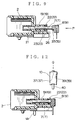
- FIG. 6 is a sectional view illustrating the first assembly step before the insertion of the sleeve
- Fig. 7 is a sectional view illustrating a provisionally inserted state in the first assembly step being halfway through the insertion of the sleeve
- Fig. 8 is a rear view of the state shown in Fig. 7
- the sleeves 7 are moved in the direction of arrow P with being held the sides thereof.
- the sleeves 7 move toward the end face of the receiving cylinder 19.
- the sleeves 7 are inserted into the receiving cylinder 19 from the end face of the receiving cylinder 19 in the direction of arrow P and then, as shown in Fig. 7, each end of the sleeves 7 comes in contact with the first projections 21.
- each sleeve 7 is halfway inserted into the receiving cylinder 19 (the provisionally inserted state).
- the assembly advances to the second step.
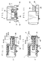
- Figure 9 is a sectional view illustrating a state, in which the optical element module is started to be pressed, in the second assembly step
- Fig. 10 is a sectional view illustrating a completely inserted state in the second assembly step after the optical element module is pressed
- Fig. 11 is a rear view of the state shown in Fig. 10.
- each of the optical element modules 8 and 9 is set on the corresponding end face of the sleeve 7, which is exposed from the receiving cylinder 19.
- the end face of the sleeve 7 is received in the second projection 35 and in this state, when each of the optical element modules 8 and 9 is pressed in the direction of arrow P, the sleeve 7 is further inserted crushing the three first projections 21, then a state (completely inserted state) shown in Fig. 10 is realized.
- each of the optical element modules 8 and 9 is inserted in and engaged with the hollow portion 23 of the receiving cylinder 19, thereby the light-emitting element and the light-receiving element are positioned so as to be aligned with the axis of the corresponding receiving cylinder 19 (the axis of the corresponding sleeve 7).
- the wall 26 prevents each of the optical element modules 8 and 9 from rotating (see Figs. 10 and 11). For example, at this time, the fixing pins 18 are fixed to the print-circuit board.
- the insertion amount of the sleeves 7 is determined by the optical element modules 8 and 9. There is no clearance between each sleeve 7 and the corresponding optical element module 8 or 9, thereby the optical loss due to the clearance is minimized. Furthermore, since the second projection 35 of each of the optical element modules 8 and 9 is inserted in and engaged with the hollow portion 23 of the receiving cylinder 19, each position of the light-emitting and light-receiving elements is aligned with the axis of the corresponding receiving cylinder 19, thereby the optical loss due to the discrepancy in the alignment between axes is reduced. (A position where the axes are aligned with each other is not limited to the position described above.)
- each of the optical element modules 8 and 9 presses the corresponding end face of each sleeve 7, the end face is free from the fat of the human hand, thereby the deterioration in the transmitting efficiency due to the assembly is prevented from occurring.
- FIG. 12 is a sectional view illustrating the third assembly step before the mounting of the shielding case
- Fig. 13 is a sectional view illustrating a state, in which the assembly is completed.
- the shielding case 10 is mounted from the direction of arrow Q. As shown in Fig. 13, the shielding case 10 engages with the engaging parts 22 to hold the optical element modules 8 and 9 therein. The shielding case 10 presses the optical element modules 8 and 9 against the end face of the respective receiving cylinders 19. Thus, each position of the optical element modules 8 and 9 is determined and fixed.
- the shielding case 10 is easily assembled.
- the hybrid connector 1 is assembled through a process including the first, second (corresponding to a second further modified assembly step described in the claims: hereinafter the same) and third assembly steps. That is, the optical connector 4 portion of the hybrid connector 1 is assembled through the first to third assembly steps described above.
- each sleeve 7 is provisionally inserted halfway through a receiving cylinder 19 of a housing 2.
- optical element modules 8 and 9 are pressed so that the sleeve 7 is further inserted into the receiving cylinder 19 to reach the completely inserted state.
- Each projection 35 of the optical element modules 8 and 9 engages with a hollow portion 23 of the receiving cylinder 19.
- the position of the optical element is aligned with the axis of the receiving cylinder 19.
- the optical element modules 8 and 9 are placed on the first wall 26 of the housing 2 or held between a pair of the walls of the housing 2 (i.e. the first wall 26 and the second wall 42).
- the assembly of the sleeves 7 and that of the optical element modules 8 and 9 are simultaneously carried out, thereby the assembly operation is simplified.
- each projection 35 of the optical element modules 8 and 9 engages with a hollow portion 23 of the receiving cylinder 19, thereby no clearance arises and each position of the optical element modules 8 and 9 is stable thereafter.
- the optical element modules 8 and 9 are placed on the first wall 26 of the housing 2 or held between a pair of the walls of the housing 2 (i.e. the first wall 26 and the second wall 42), thereby the positional shift of the optical element modules 8 and 9 due to the rotation thereof is prevented from occurring and each position of the optical element modules 8 and 9 is stable thereafter. Therefore, the workability improves and the optical loss is reduced.
- the shielding case 10 holds the optical element modules 8 and 9.
- the case 10 engages with the receiving cylinders 19, then each position of the optical element modules 8 and 9 is fixed. Since these assemblies are carried out simultaneously, the assembly operation is simplified. If a moving length of the sleeve 7 in the receiving cylinder 19 in the second assembly step is set shorter than that in the first assembly step, the labor required for press-insertion of the sleeve 7 is reduced.
- the hybrid connector 1 Since the hybrid connector 1 is constructed as described above, the position of the optical element can be aligned with the axis of the corresponding receiving cylinder 19 and the positional shift of the optical element modules 8 and 9 due to the rotation thereof is prevented from occurring, thereby each position of the optical element modules 8 and 9 is stable thereafter. Therefore, the workability improves and the optical loss is reduced.
- Figure 16 is an exploded perspective view of a hybrid connector according to the another preferred embodiment of the present invention and Fig. 17 is a sectional view of a housing.
- a male hybrid connector 51 to be mounted on a print-circuit board (not shown in the figure).
- the hybrid connector 51 includes electrical connectors 53 and optical connectors 54, which share a housing 52 with each other.
- the hybrid connector 51 is constructed so that the assembling operation thereof can be easily carried out as well as the hybrid connector 1 described above (see Fig. 1) and the optical element modules 8 and 9 described above can be stably positioned upon the assembly.
- the hybrid connector 51 is connected to a female hybrid connector similarly to the female hybrid connector 5 in Fig. 1.
- a corresponding lens sleeve 56 explained later on is optically combined. That is, both optical axes are aligned with each other.
- the electric connector 53 consists of the housing 52 and electric terminals (PCB terminals) 6 described above.
- the optical connector 54 consists of the housing 52, the sleeve holder 55, lens sleeves 56 (corresponding to the sleeves described in the claims), optical element modules 8 and 9, and a shielding case 57 (corresponding to the case described in the claims).
- the housing 52 made of an insulative synthetic resin is formed in a rectangular box shape, in which a flont face 58 is opened. That is, the housing 52 is formed in a rectangular box shape with an upper wall 59, bottom wall 60, right sidewall 61, left sidewall 62 and an inside wall 63.
- the upper wall 59 is provided with a lock portion, with which a locking arm formed on the hybrid connector 51 (see Fig. 16) engaged.
- Each of the right sidewall 61 and the left sidewall 62 is provided with a corresponding pocket 64 for receiving a fixing pin 65 made of metal therein and engaging with the same.
- Each pocket 64 is provided with a through hole, which is opened at the print-circuit board side, and a part of the fixing pin 65 is fixed to the print-circuit board through the through hole.
- the inside wall 63 of the housing 52 is provided integrally with a pair of receiving cylinders 66, each of which has a notched portion 67.
- the receiving cylinder 66 is formed in a cylindrical shape so that the inner cross section thereof is round when the sleeve holder 55 is inserted into the housing 52 (i.e., into the receiving cylinder 66 in this preferred embodiment) so as to close the notched portion 67.
- the receiving cylinder 66 has a length in accordance with the length of the lens sleeve 56.
- the receiving cylinder 66 protrudes toward an engaging space 68 in the housing 52 for engaging with the hybrid connector 51 (see Fig. 17) and is formed to also protrude toward the rear of the inside wall 63.
- each ferrule described above is inserted from the engaging space 68 side.
- each receiving cylinder 66 On an inner face of each receiving cylinder 66, there are formed a stopper 69 (one of which being shown in the figure) against the corresponding lens sleeve 56 and a fifth projection 70 for aligning the optical axes.
- the stopper 69 is formed at the engaging space 68 side so that a flange 88 (explained later on) of the lens sleeve 56 abuts against the stopper 69.
- the fifth projection 70 is formed at the rear side of the inside wall 63 so as to hold an optical waveguide 86 (explained later on) of the lens sleeve 56.
- the fifth projection 70 is formed in a triangular shape in the cross section thereof so as to put the optical waveguide 86 thereon, thereby holding the optical waveguide 86. (The top of the fifth projection 70 can be crushed to align the optical axes.)
- each receiving cylinder 66 On the outside end of each receiving cylinder 66 at the side from which the lens sleeve 56 is inserted, a corresponding engaging part 71 is integrally formed with the receiving cylinder 66. On an end face of the outside end, there is formed a hollow portion 72 depressed along the axis of the receiving cylinder 66. On the outside end of each receiving cylinder 66 at the side of the right sidewall 61 and the left sidewall 62, there is provided a step 73 (only one of which being shown in the figure). In addition, at the bottom wall 60 side thereof, a leg 74 is continuously formed.
- a shielding case 57 engages with the engaging part 71 and the thickness of the engaging part 71 is formed to give an enough stiffness threreto so that it can resist against a force acting along the axis of the receiving cylinder 66.
- the engaging part 71 may be formed with reference to the engaging part 22 (see Fig. 1) described above.
- the diameter of a hollow 72 is larger than the inner diameter of the receiving cylinder 66.
- the hollow 72 engages with a second projection 35 of the optical element module 8 and 9.
- Each step 73 engages with a corresponding stopper 94 (explained later on) of the shielding case 57.
- a leg 74 including a guide portion 75 is formed in a letter H-shape in a cross sectional view thereof.
- a horizontal wall 81 (explained later on) of the sleeve holder 55 can come into and out from the guide portion 75.
- the portion of the receiving cylinder 66 which protrudes rearward exceeding the end face of the end of the receiving cylinder 66, is provided with a first wall 76, which is similar in terms of the function to the first wall 26 (see Fig, 15) described above.
- the first wall 76 serves as a stopper to prevent the optical element modules 8 or 9 from rotating and is formed to have a flat surface.
- each second wall 77 facing the first wall 76 is provided with the engaging part 71. (The first wall 76 and second wall 77 hold the optical element modules 8 or 9 therebetween so as to prevent the optical element modules 8 or 9 from rotating.)
- the sleeve holder 55 is made of synthetic resin and formed so as to hold a pair of the lens sleeves 56 together with a pair of the receiving cylinders 66 when the sleeve holder is inserted into the housing 52. That is, the sleeve holder 55 consists of a pair of holder portions 79 for holding the lens sleeves 56 by closing the notched portion 67 of the receiving cylinder 66, the perpendicular wall 80 formed between a pair of the holder portions 79, and a horizontal wall 81 continuously formed with an end of the perpendicular wall 80.
- Each holder portion 79 is provided with a corresponding press part 82, which abuts against a corresponding flange 88 (explained later on) of the lens sleeve 56 at the front end of the holder portion 79.
- Each holder portion 79 is also provided with a corresponding sixth projection 83 (Only one of the projections 83 is shown and the projections 83 has the same function as the fifth projection 70.) for aligning the optical axes, which is matched with the projection 70 of the receiving cylinder 66 on an inner surface of the holder portion 79.
- each holder portion 79 is provided with a hollow portion 84 (see Fig. 20; only one of the hollow portions 84 being shown) continuing to the hollow portion 72 of the receiving cylinder 66 and a wall 85 (corresponding to the second wall described in the claims) having the function of the second wall 77 at the rear end of the holder portion 79.
- the perpendicular wall 80 is formed as a portion, which is guided by the slit of the receiving cylinder.
- the horizontal wall 81 is formed as a portion, which is guided by the guide portion 75.
- the lens sleeve 56 is made of transparent synthetic regin or glass.
- Each lens sleeve 56 consists of a cone-shaped optical waveguide 86 having a tapered side thereof, a convex lens 87 formed at the end face of the optical waveguide 86 at the large diameter side thereof, and the flange 88 protrudingly formed toward the outside of the convex lens 87.
- the convex lens 87 faces an end of the ferrule and the end face of the optical waveguide 86 at the small diameter side thereof faces the light-emitting element (not shown in the figure) or the light-receiving element (not shown in the figure) of the optical element module 8 or 9.
- the optical waveguide 86 On the side of the optical waveguide 86, there is formed an air layer, at the boundary of which the light transmitting through the optical waveguide 86 is totally reflected.
- the face of the flange 88 at the convex lens 87 side abuts against the stopper 69 of the receiving cylinder 66.
- the press part 82 of the sleeve holder 55 abuts against the face of the flange 88 at the optical waveguide 86 side thereof. In other wards, the lens sleeve 56 is pressed by the press part 82 and positioned by abutting against the stopper 69.
- the sleeve is not limited to the lens sleeve 56 having the convex lens 87.
- the sleeve only has to have the flange 88 and may be a sleeve having no convex lens 87 or a sleeve, in which a pair of the optical waveguides 86 is straightly formed.
- the shielding case 57 formed by pressing an electrically conductive metal sheet, has a spring property useful upon the assembly and so on.
- the shielding case 57 has two receiving parts 90 partitioned by a wall 89.
- the receiving part 90 receives the optical element module 8 or 9.
- the optical element modules 8 and 9 are press-held with the aid of said spring property.
- Each receiving part 90 consists of a U-shaped notched portion 91, a fourth projection 92 (see Fig. 23; Only one of them is shown.) that presses the optical element module 8 or 9 onto the notched portion 91 side, and a leg 93 (Only three of four legs are shown.) for fixing the case 57 on the print-circuit board.
- the shielding case 57 has a spring property so that each of the optical element modules 8 and 9 can be pressed onto the end face of the corresponding receiving cylinders 66, the case 57 can be made of an electrically conductive synthetic resin containing carbon fibers and the like.
- the electrically conductive case 57 improves the shielding property thereof for the optical element modules 8 and 9.
- Each notched portion 91 is formed in accordance with the outer diameter of the receiving cylinder 66, at the periphery of which a projecting stopper 94 protruding inwardly is formed.
- Each fourth projection 92 (see Fig. 23; Only one of the two being shown) is formed on the rear wall situated at the opposite side of the front wall, on which the corresponding notched portion 91 is formed.
- the fourth projection 92 is protrudingly formed, for example, in an ellipse shape by an embossing press.
- Each leg 93 for fixing the case 57 on the print-circuit board is continuously formed to the sidewall of the receiving parts 90 and is fixed on the print-circuit board.
- the leg 93 functions as a ground terminal.
- the optical connector 54 portion is to be assembled in sequence through a first assembly step with a sleeve holder, a second assembly step with a sleeve holder, and a third assembly step with a sleeve holder.
- the second assembly step with a sleeve holder described above corresponds to a second further modified assembly step with a sleeve holder described in claims of the present specification.
- a second assembly step with a sleeve holder described in the claims excludes the contents of the first wall 76 (also the wall 85 and the second wall 77) from the following explanation.
- a second modified assembly step with a sleeve holder described in the claims excludes the contents of the second projection 35 and the hollow portions 72 and 84 from the following explanation.
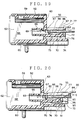
- Figure 18 is a sectional view illustrating a first assembly step with a sleeve holder before the insertion of the lens sleeve (sleeve).
- Figure 19 is a sectional view illustrating a first assembly step with a sleeve holder when the lens sleeve is set against the receiving cylinder.
- Figure 20 is a sectional view illustrating a first assembly step with a sleeve holder when the lens sleeve is on the way to be inserted into the receiving cylinder by the sleeve holder.
- Figure 21 is a sectional view illustrating a first assembly step with a sleeve holder when the lens sleeve is provisionally inserted into the receiving cylinder.
- the lens sleeves 56 are moved in the direction of arrow R with being held the sides thereof and set up at a position in the receiving cylinder 66 as shown in Fig. 19.
- the flange 88 of the lens sleeve 56 is situated between the stopper 69 and the fifth projection 70 of the receiving cylinder 66.
- the sleeve holder 55 is moved in the direction of arrow S so as to start the insertion thereof into the housing 52.
- the press part 82 of the sleeve holder 55 abuts against the flange 88 of the lens sleeve 56 and the lens sleeve 56 moves (i.e. being press-inserted) in the direction of arrow S as the sleeve holder 55 moves.
- the first assembly step with a sleeve holder is completed.
- the lens sleeve 56 is in a provisionally inserted state thereof and the notched portion 67 of the receiving cylinder 66 is closed by the sleeve holder 55. Then, the process advances to the second assembly step with a sleeve holder.
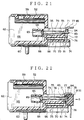
- Figure 22 is a sectional view illustrating a second assembly step with a sleeve holder when the lens sleeve is completely inserted into the receiving cylinder after the optical element module is pressed.
- the optical element modules 8 and 9 are set up at the corresponding end face side of the lens sleeve 56, which is exposed from the receiving cylinder 66 and the sleeve holder 55. Then, the optical element modules 8 and 9 are moved in the direction of the arrow S so that the optical element modules 8 and 9 are pressed onto the end of the sleeve holder 55 and/or the end face of the lens sleeve 56, thereby the lens sleeve 56 is in a completely inserted state into the receiving cylinder 66.
- the end face of the lens sleeve 56 is received in the second projection 35 of the optical element module 8 or 9.
- the second projection 35 of the optical element module 8 or 9 is inserted into and engaged with the hollow portion 72 of the receiving cylinder 66 and the hollow portion 84 of the sleeve holder 55.
- each position of the light-emitting element and the light-receiving element of the optical element modules 8 and 9 is aligned with the axis of the receiving cylinder 66 (i.e. the axis of the lens sleeve 56).
- the optical element modules 8 and 9 are held among the first wall 76, the second wall 77 and the wall 85 so as to be prevented from rotating.
- a pair of fixing pins 65 (see Fig. 16) is also mounted in the second assembly step with a sleeve holder.
- the insertion amount of the lens sleeves 56 is determined by the optical element modules 8 and 9.
- the optical loss due to the clearance between the lens sleeve 56 and the optical element modules 8 and 9 is minimized. Furthermore, since the second projection 35 of each of the optical element modules 8 and 9 is inserted in and engaged with the hollow portion 72 of the receiving cylinder 66 and the hollow portion 84 of the sleeve holder 55, each position of the light-emitting and light-receiving elements is aligned with the axis of the corresponding receiving cylinder 66, thereby the optical loss due to the discrepancy in the alignment between axes is reduced.
- each of the optical element modules 8 and 9 presses the corresponding end face of the lens sleeve 56, the end face of the lens sleeve 56 is free from the fat of the human hand, thereby the deterioration in the transmitting efficiency due to the assembly is prevented from occurring.
- Figure 23 is a sectional view illustrating a second assembly step with a sleeve holder after the shielding case is mounted.
- the shielding case 57 is mounted from the direction of arrow T. At this time, the shielding case 57 engages with the engaging parts 71 to hold the optical element modules 8 and 9 therein. The shielding case 57 presses the optical element modules 8 and 9 against the end face of the respective receiving cylinders 66. Thus, each position of the optical element modules 8 and 9 is determined and fixed.
- the shielding case 57 is easily assembled.
- the hybrid connector 51 is assembled through a process including the first assembly step with a sleeve holder, the second assembly step with a sleeve holder (corresponding to the second further modified assembly step with a sleeve holder described in the claims: hereinafter the same) and third assembly step with a sleeve holder. That is, the optical connector 54 portion of the hybrid connector 51 is assembled through the first to third assembly steps with a sleeve holder described above.
- each lens sleeve 56 is provisionally inserted halfway through a receiving cylinder 66 of a housing 52.
- optical element modules 8 and 9 are pressed so that the lens sleeve 56 is further inserted into the receiving cylinder 66 to reach the completely inserted state.
- each projection 35 of the optical element modules 8 and 9 engages with the hollow portion 72 of the housing 52 side and/or the hollow portion 84 of the sleeve holder 55 side, thereby the position of the optical element is aligned with the axis of the receiving cylinder 66.
- the optical element modules 8 and 9 are held between a pair of the walls (the first wall 76, the sencond wall 77 and the wall 85) of the housing 52 and the sleeve holder 55.
- Each projection 35 of the optical element modules 8 and 9 engages with the hollow portion 72 of the housing 52 side and/or the hollow portion 84 of the sleeve holder 55 side, thereby no clearance arises and each position of the optical element modules 8 and 9 is stable thereafter.
- the optical element modules 8 and 9 are held between a pair of the walls (the first wall 76, the sencond wall 77 and the wall 85) of the housing 52 and the sleeve holder 55, thereby the positional shift of the optical element modules 8 and 9 due to the rotation thereof is prevented from occurring and each position of the optical element modules 8 and 9 is stable thereafter. Therefore, the workability improves and the optical loss is reduced.
- the shielding case 57 holds the optical element modules 8 and 9.
- the case 57 engages with the receiving cylinders 66, then each position of the optical element modules 8 and 9 is fixed.
- the hybrid connector 51 is constructed as described above, the postion of the optical element can be aligned with the axis of the receiving cylinder 66.
- the undesired positional shift of the optical element modules 8 and 9 due to the rotation thereof is prevented from occurring. Therefore, the position of the optical element modules 8 and 9 is stabilized, the workability improves, and the optical loss is reduced.
- the process for assembling the hybrid connector 51 can also be characterized as follows:
- the process for assembling (the first to third assembly steps) according to the present invention can be applied to the assembly of a normal optical connector.
- the present invention can also be applied to a use for bidirectional communication employing single-core optical fibers.
Abstract
Description
- The present invention relates to a hybrid connector, in which electric and optical connectors are integrally formed, so that a simple connecting operation completes the connection between the electric and optical connectors, and to a process for assembling the hybrid connector.
- With regard to various vehicles including motorcars, extremely many signals from various sensors and those for controlling various electronic equipments have to be handled. When these signals are transmitted by using individual signal lines, the number of the signal lines becomes enormous, causing a wiring harness to be very heavy. In addition, in recent years, informations transmitted from various electronic equipments have been enhanced and much denser, causing a wiring harness to be furthermore heavy. Therefore, recently, a part of a wiring harness has been replaced by an optical fiber cable (optical fiber cord) and for example, a system in which an optical fiber cable connects nodes with each other has been employed.
- When a part of a wiring harness is to be replaced by an optical fiber cable, for example for a motorcar manufacturer, an operation for connecting the electric and optical connectors becomes complicated and troublesome. Consequently, recently, a hybrid connector, in which electric and optical connectors are integrally formed so that a single connecting operation completes the connection between the electric and optical connectors, has been developed for its practical use.
- However, since the hybrid connector is formed in such a way that the electric and optical connectors are integrally constituted therein, the hybrid connector is forced to have many components. Especially, the assembly of the optical connector is troublesome because it requires many man-hours. Furthermore, there has been a problem that optical element modules constituting the optical connector can not be stably positioned upon the assembly.
- If the optical element modules can not be stably positioned upon the assembly, it affects the warkability of the assembling operation and sometimes affects the optical loss characteristic after the assembly.
- It is therefore an objective of the present invention to solve the problem described above and to provide a process for assembling a hybrid connector, by which the assmbling operation can be simplified and the optical element modules can be stably positioned so that the workability of the assembling operation is improved and the optical loss is reduced, as well as to provide such a hybrid connector.
- In order to attain the above objective, a first aspect of the present invention is to provide a process for assembling a male hybrid connector having electric and optical connectors formed integrally with each other, the optical connector including: at least one optical element module having an optical element; sleeves, each of which has an optical waveguide, provided in accordance with the number of the optical element modules; a housing shared with the electric connector, the housing having receiving cylinders for holding the sleeves therein; and a case for holding the optical element modules, the process comprising the steps of:
- a first assembly step of reaching a provisionally inserted state, in which each sleeve is halfway inserted into the corresponding receiving cylinder;
- a second assembly step of reaching a completely inserted state, in which each optical element module is pressed against an end face of the corresponding sleeve exposed from the receiving cylinder so as to further insert the sleeve into the corresponding receiving cylinder, and then engaging each second projection formed on the optical element module with a corresponding hollow portion formed in the receiving cylinder so as to align a position of the optical element with an axis of the corresponding receiving cylinder; and
- a third assembly step of engaging the case with the receiving cylinder, while the case holding the optical element modules, so as to fix a position of the optical element module.
-
- According to the constitution described above, the hybrid connector is assembled through a process including the first to third assembly steps. That is, the optical connector portion of the hybrid connector is assembled in the first to third assembly steps.
- In the first assembly step, the sleeve is provisionally halfway inserted into the receiving cylinder of the housing. In the second assembly step, the optical element module is pressed so as to insert the sleeve further into the receiving cylinder, thereby the sleeve is completely (fully) inserted into the receiving cylinder. At this time, the projection of the optical element module engages with the hollow portion of the housing side, thereby the position of the optical element is aligned with the axis of the receiving cylinder.
- In the second assembly step, the assembly of the sleeve and that of the optical element modules are carried out simultaneously, thereby the assembly operation is simplified.
- In the second assembly step, each projection of the optical element modules engages with the hollow portion of the receiving cylinder, thereby no clearance arises and each position of the optical element modules is stable thereafter. Therefore, the workability improves and the optical loss is reduced.
- In the second assembly step, the optical element module is pressed against the sleeve so that the sleeve is inserted into the receiving cylinder, thereby the optical loss due to the clearance between the sleeve and the optical element module is minimized.
- In the third assembly step, the case holds the optical element modules. The case engages with the receiving cylinders, then each position of the optical element modules is fixed. Since these assemblies are carried out simultaneously, the assembly operation is simplified. Since the position of the optical element module is stable, the workability for assembling the case is improved.
- A second aspect of the present invention is to provide a process for assembling a male hybrid connector having electric and optical connectors formed integrally with each other, the optical connector including: at least one optical element module having an optical element; sleeves, each of which has an optical waveguide, provided in accordance with the number of the optical element modules; a housing shared with the electric connector, the housing having receiving cylinders for holding the sleeves therein; and a case for holding the optical element modules, the process comprising the steps of:
- a first assembly step of reaching a provisionally inserted state, in which each sleeve is halfway inserted into the corresponding receiving cylinder;
- a second modified assembly step of reaching a completely inserted state, in which each optical element module is pressed against an end face of the corresponding sleeve exposed from the receiving cylinder so as to further insert the sleeve into the corresponding receiving cylinder, and then placing the optical element module on a first wall formed in the housing or holding the optical element module between a pair of walls formed in the housing so as to prevent the optical element module from rotating; and
- a third assembly step of engaging the case with the receiving cylinder, while the case holding the optical element modules, so as to fix a position of the optical element module.
-
- According to the constitution described above, the hybrid connector is simply assembled. The position of the optical element module is stabilized so as to improve the workability and to reduce the optical loss.
- A third aspect of the present invention is to provide a process for assembling a male hybrid connector having electric and optical connectors formed integrally with each other, the optical connector including: at least one optical element module having an optical element; sleeves, each of which has an optical waveguide, provided in accordance with the number of the optical element modules; a housing shared with the electric connector, the housing having receiving cylinders for holding the sleeves therein; and a case for holding the optical element modules, the process comprising the steps of:
- a first assembly step of reaching a provisionally inserted state, in which each sleeve is halfway inserted into the corresponding receiving cylinder;
- a second further modified assembly step of reaching a completely inserted state, in which each optical element module is pressed against an end face of the corresponding sleeve exposed from the receiving cylinder so as to further insert the sleeve into the corresponding receiving cylinder, then engaging each second projection formed on the optical element module with a corresponding hollow portion formed in the receiving cylinder so as to align a position of the optical element with an axis of the corresponding receiving cylinder, and then placing the optical element module on a first wall formed in the housing or holding the optical element module between a pair of walls formed in the housing so as to prevent the optical element module from rotating; and
- a third assembly step of engaging the case with the receiving cylinder, while the case holding the optical element modules, so as to fix a position of the optical element module.
-
- According to the constitution described above, the hybrid connector is simply assembled. The position of the optical element module is stabilized so as to improve the workability and to reduce the optical loss.
- Preferably, in the first assembly step, the sleeve is inserted into the receiving cylinder until the sleeve comes into contact with first projections formed in the receiving cylinder for press-inserting the sleeve, and in the second, second modified or second further modified assembly step, the sleeve is press-inserted into the receiving cylinder crushing the first projections.
- According to the constitution described above, the sleeve is smoothly inserted in the first assembly step, thereby the assembly operation can be simplified further.
- Preferably, a moving length of the sleeve in the receiving cylinder in the second, second modified or second further modified assembly step is shorter than that in the first assembly step.
- According to the constitution described above, in the second (second modified or second further modified) assembly step, the labor required for press-insertion of the sleeve is reduced, thereby the assembly operation can be simplified further.
- A fourth aspect of the present invention is to provide a process for assembling a male hybrid connector having electric and optical connectors formed integrally with each other, the optical connector including: at least one optical element module having an optical element; sleeves, each of which has an optical waveguide, provided in accordance with the number of the optical element modules; a housing shared with the electric connector, the housing having receiving cylinders for holding the sleeves therein; a sleeve holder to be inserted in the housing for holding the sleeves together with the receiving cylinders; and a case for holding the optical element modules, the process comprising the steps of:
- a first assembly step with a sleeve holder of setting the sleeves in the receiving cylinder, fitting the sleeve holder thereto and inserting each sleeve into the corresponding receiving cylinder by the sleeve holder so that each sleeve is provisionally inserted into the corresponding receiving cylinder;
- a second assembly step with a sleeve holder of pressing each optical element module against an end face of the corresponding sleeve exposed from the receiving cylinder and/or an end of the sleeve holder so that each sleeve is completely inserted into the corresponding receiving cylinder and then engaging each second projection formed on the optical element module with corresponding hollow portions formed in the receiving cylinder and/or on the sleeve holder so as to align a position of the optical element with an axis of the corresponding receiving cylinder; and
- a third assembly step with a sleeve holder of engaging the case with the receiving cylinder, while the case holding the optical element modules, so as to fix a position of the optical element module.
-
- According to the constitution described above, the hybrid connector is simply assembled. The position of the optical element module is stabilized so as to improve the workability and to reduce the optical loss.
- The optical loss due to the clearance between the sleeve and the optical element module is minimized. The end face of the sleeve is free from the fat of the human hand, thereby the deterioration in the transmitting efficiency due to the assembly is prevented from occurring.
- A fifth aspect of the present invention is to provide a process for assembling a male hybrid connector having electric and optical connectors formed integrally with each other, the optical connector including: at least one optical element module having an optical element; sleeves, each of which has an optical waveguide, provided in accordance with the number of the optical element modules; a housing shared with the electric connector, the housing having receiving cylinders for holding the sleeves therein; a sleeve holder to be inserted in the housing for holding the sleeves together with the receiving cylinders; and a case for holding the optical element modules, the process comprising the steps of:
- a first assembly step with a sleeve holder of setting the sleeves in the receiving cylinder, fitting the sleeve holder thereto and inserting each sleeve into the corresponding receiving cylinder by the sleeve holder so that each sleeve is provisionally inserted into the corresponding receiving cylinder;
- a second modified assembly step with a sleeve holder of pressing each optical element module against an end face of the corresponding sleeve exposed from the receiving cylinder and/or an end of the sleeve holder so that each sleeve is completely inserted into the corresponding receiving cylinder and then placing the optical element module on a wall formed in the housing and/or the sleeve holder or holding the optical element module between a pair of walls formed in the housing and/or the sleeve holder so as to prevent the optical element module from rotating; and
- a third assembly step with a sleeve holder of engaging the case with the receiving cylinder, while the case holding the optical element modules, so as to fix a position of the optical element module.
-
- A sixth aspect of the present invention is to provide a process for assembling a male hybrid connector having electric and optical connectors formed integrally with each other, the optical connector including: at least one optical element module having an optical element; sleeves, each of which has an optical waveguide, provided in accordance with the number of the optical element modules; a housing shared with the electric connector, the housing having receiving cylinders for holding the sleeves therein; a sleeve holder to be inserted in the housing for holding the sleeves together with the receiving cylinders; and a case for holding the optical element modules, the process comprising the steps of:
- a first assembly step with a sleeve holder of setting the sleeves in the receiving cylinder, fitting the sleeve holder thereto and inserting each sleeve into the corresponding receiving cylinder by the sleeve holder so that each sleeve is provisionally inserted into the corresponding receiving cylinder;
- a second further modified assembly step with a sleeve holder of pressing each optical element module against an end face of the corresponding sleeve exposed from the receiving cylinder and/or an end of the sleeve holder so that each sleeve is completely inserted into the corresponding receiving cylinder, then engaging each second projection formed on the optical element module with a corresponding hollow portion formed in the housing and/or the sleeve holder so as to align a position of the optical element with an axis of the corresponding receiving cylinder, and then placing the optical element module on a wall formed in the housing and/or the sleeve holder or holding the optical element module between a pair of walls formed in the housing and/or the sleeve holder so as to prevent the optical element module from rotating; and
- a third assembly step with a sleeve holder of engaging the case with the receiving cylinder, while the case holding the optical element modules, so as to fix a position of the optical element module.
-
- In order to attain the objective, a seventh aspect of the present invention is to provide a male hybrid connector including electric and optical connectors formed integrally with each other, the optical connector comprising:
- at least one optical element module having an optical element;
- sleeves, each of which has an optical waveguide, provided in accordance with the number of the optical element modules;
- a housing shared with the electric connector, the housing having receiving cylinders for holding the sleeves therein; and
- a case for holding the optical element modules and positioning the
optical element modules with respect to the housing,
wherein a hollow portion depressed along an axis of the receiving cylinder is formed in the receiving cylinder at the side into which the sleeve is inserted and each optical element module is provided with a second projection for engaging with the hollow portion and aligning the position of the optical element with the axis. -
- According to the constitution described above, the projection of the optical element module is formed so as to engage with the hollow portion of the housing side, thereby the position of the optical element can be aligned with the axis of the receiving cylinder. The engagement stablizes the position of the optical element module, thereby the workability improves and the optical loss is reduced.
- An eighth aspect of the present invention is to provide a male hybrid connector including electric and optical connectors formed integrally with each other, the optical connector comprising:
- at least one optical element module having an optical element;
- sleeves, each of which has an optical waveguide, provided in accordance with the number of the optical element modules;
- a housing shared with the electric connector, the housing having receiving cylinders for holding the sleeves therein; and
- a case for holding the optical element modules and positioning the
optical element modules with respect to the housing,
wherein a first wall is formed in the housing at the side into which the sleeve is inserted so that the first wall places the optical element modules thereon and prevents the optical elemnet modules from rotating before the case covers the optical elemnet modules. -
- According to the constitution described above, the positional shift of the optical element modules due to the rotation thereof is prevented from occurring and each position of the optical element modules is stabilized. Therefore, the workability improves and the optical loss is reduced.
- A ninth aspect of the present invention is to provide a male hybrid connector including electric and optical connectors formed integrally with each other, the optical connector comprising:
- at least one optical element module having an optical element;
- sleeves, each of which has an optical waveguide, provided in accordance with the number of the optical element modules;
- a housing shared with the electric connector, the housing having receiving cylinders for holding the sleeves therein; and
- a case for holding the optical element modules and positioning the
optical element modules with respect to the housing,
wherein a first wall is formed in the housing at the side into which the sleeve is inserted so that the first wall places the optical element modules thereon and prevents the optical elemnet modules from rotating before the case covers the optical elemnet modules,
a hollow portion depressed along an axis of the receiving cylinder is formed in the receiving cylinder at the side into which the sleeve is inserted, and
each optical element module is provided with a second projection for engaging with the hollow portion and aligning the position of the optical element with the axis. -
- According to the constitution described above, the position of the optical element module is stabilized, thereby the workability improves and the optical loss is reduced.
- Preferably, a second wall, which faces the first wall and holds the optical element modules between the first and second walls, is formed on the receiving cylinder.
- According to the constitution described above, the optical element module is securely prevented from rotating, thereby the workability further improves and the optical loss is further reduced.
- A tenth aspect of the present invention is to provide a male hybrid connector including electric and optical connectors formed integrally with each other, the optical connector comprising:
- at least one optical element module having an optical element;
- sleeves, each of which has an optical waveguide, provided in accordance with the number of the optical element modules;
- a housing shared with the electric connector, the housing having receiving cylinders for holding the sleeves therein;
- a sleeve holder to be inserted in the housing for holding the sleeves together with the receiving cylinders; and
- a case for holding the optical element modules and positioning the
optical element modules with respect to the housing,
wherein a hollow portion depressed along an axis of the receiving cylinder is formed in the receiving cylinder at the side into which the sleeve is inserted and/or on an end of the sleeve holder, and each optical element module is provided with a second projection for engaging with the hollow portion and aligning the position of the optical element with the axis. -
- According to the constitution described above, the position of the optical element module is stabilized so as to improve the workability and to reduce the optical loss.
- An eleventh aspect of the present invention is to provide a male hybrid connector including electric and optical connectors formed integrally with each other, the optical connector comprising:
- at least one optical element module having an optical element;
- sleeves, each of which has an optical waveguide, provided in accordance with the number of the optical element modules;
- a housing shared with the electric connector, the housing having receiving cylinders for holding the sleeves therein;
- a sleeve holder to be inserted in the housing for holding the sleeves together with the receiving cylinders; and
- a case for holding the optical element modules and positioning the
optical element modules with respect to the housing,
wherein a first wall is formed in the housing at the side into which the sleeve is inserted and/or on an end of the sleeve holder so that the first wall places the optical element modules thereon and prevents the optical elemnet modules from rotating before the case covers the optical elemnet modules. -
- A twelfth aspect of the present invention is to provide a male hybrid connector including electric and optical connectors formed integrally with each other, the optical connector comprising:
- at least one optical element module having an optical element;
- sleeves, each of which has an optical waveguide, provided in accordance with the number of the optical element modules;
- a housing shared with the electric connector, the housing having receiving cylinders for holding the sleeves therein;
- a sleeve holder to be inserted in the housing for holding the sleeves together with the receiving cylinders; and
- a case for holding the optical element modules and positioning the
optical element modules with respect to the housing,
wherein a first wall is formed in the housing at the side into which the sleeve is inserted and/or on an end of the sleeve holder so that the first wall places the optical element modules thereon and prevents the optical elemnet modules from rotating before the case covers the optical elemnet modules,
a hollow portion depressed along an axis of the receiving cylinder is formed in the receiving cylinder at the side into which the sleeve is inserted, and
each optical element module is provided with a second projection for engaging with the hollow portion and aligning the position of the optical element with the axis. -
- Preferably, a second wall, which faces the first wall and holds the optical element modules between the first and second walls, is formed on the receiving cylinder and/or the sleeve holder.
-
- Figure 1 is an exploded perspective view of a hybrid connector according to a preferred embodiment of the present invention;
- Figure 2 is a front view of the hybrid connector;
- Figure 3 is a plan view of the hybrid connector;
- Figure 4 is a left side view of the hybrid connector;
- Figure 5 is a right side view of the housing;
- Figure 6 is a sectional view illustrating a first assembly step before the insertion of the sleeve;
- Figure 7 is a sectional view illustrating a provisionally inserted state in the first assembly step being halfway through the insertion of the sleeve;
- Figure 8 is a rear view of the state shown in Fig. 7;
- Figure 9 is a sectional view illustrating a state, in which the optical element module is started to be pressed, in a second assembly step;
- Figure 10 is a sectional view illustrating a completely inserted state in a second assembly step after the optical element module is pressed;
- Figure 11 is a rear view of the state shown in Fig. 10;
- Figure 12 is a sectional view illustrating a third assembly step before the mounting of the shielding case;
- Figure 13 is a sectional view illustrating a state, in which the assembly is completed;
- Figure 14 is a right side view illustrating another example of the housing;
- Figure 15 is a perspective view illustating the primary part of the view shown in Fig. 14;
- Figure 16 is an exploded perspective view of a hybrid connector according to another preferred embodiment of the present invention;
- Figure 17 is a sectional view (longitudinal sectional view taking the center of the receiving cylinder at the electric connector side as the standard) of a housing shown in Fig. 16;
- Figure 18 is a sectional view illustrating a first assembly step with a sleeve holder before the insertion of the lens sleeve (sleeve);
- Figure 19 is a sectional view illustrating a first assembly step with a sleeve holder when the lens sleeve is set in the receiving cylinder;
- Figure 20 is a sectional view illustrating a first assembly step with a sleeve holder when the lens sleeve is on the way to be inserted into the receiving cylinder by the sleeve holder;
- Figure 21 is a sectional view illustrating a first assembly step with a sleeve holder when the lens sleeve is provisionally inserted into the receiving cylinder;
- Figure 22 is a sectional view illustrating a second assembly step with a sleeve holder when the lens sleeve is completely inserted into the receiving cylinder after the optical element module is pressed; and
- Figure 23 is a sectional view illustrating a second assembly step with a sleeve holder after the shielding case (case) is mounted.
-
- In the following, the preferred embodiments of the present invention will be explained with reference to the attached drawings.
- Figure 1 is an exploded perspective view of a hybrid connector according to a preferred embodiment of the present invention. Figure 2 is a front view of the hybrid connector; Figure 3 is a plan view of the hybrid connector; Figure 4 is a left side view of the hybrid connector; and Figure 5 is a right side view of the housing.
- In the present specification, the hybrid connector is defined as a connector, in which electric and optical connectors are integrally formed.
- In Fig. 1, the reference numeral 1 denotes a male hybrid connector to be mounted on a print-circuit board, which is not shown in the figure. The hybrid connector 1 comprises an
electric connector 3 and anopetical connetor 4, both of which share ahousing 2. As explained later on, the hybrid connector according to the present invention is constructed so that the assembling operation thereof can be easily carried out and theoptical element modules - The hybrid connector 1 is connected to a female hybrid connector 5, in which two optical fiber cables (optical fiber cords; not shown in the figure), on each end of which a corresponding ferrule is mounted, are mounted in parallel in a housing of the female hybrid connector 5. Out of the two optical fiber cables, one is for transmitting while the other is for receiving. On an end face of the ferrule, there is exposed a core portion ((plastic) optical fiber consisting of a core and a clad), an optical axis of which aligns with that of a respective
optical waveguide 28 in asleeve 7 explained later on. - The
electric connector 3 consists of thehousing 2 and electric terminals (PCB terminals) 6. Theoptical connector 4 consists of thehousing 2, thesleeves 7,optical element modules case 10. Theoptical element modules optical connector 4 may be called a receiving/emission module, receiving/ transmitting module or a fiber optic transceiver (FOT). The shieldingcase 10 corresponds to the case described in the claims. - In the following, each element of the hybrid connector 1 will be explained with reference to Figs. 1 - 5, thereafter the assembly (method of the assembly) of the hybrid connector 1 will be explained in detail.
- The
housing 2 made of an insulative synthetic resin is formed in a rectangular box shape, in which aflont face 11 is opened. That is, thehousing 2 is formed in a rectangular box shape with anupper wall 12,bottom wall 13,right sidewall 14, leftsidewall 15 and aninside wall 16. Theupper wall 12 is provided with a lock portion, with which a locking arm formed on the hybrid connector 5 engaged. Each of theright sidewall 14 and theleft sidewall 15 is provided with acorresponding pocket 17 for receiving a fixingpin 18 made of metal therein and engaging with the same. Eachpocket 17 is provided with a through hole, which is opened at the print-circuit board side, and a part of the fixingpin 18 is fixed to the print-circuit board through the through hole. - The
inside wall 16 of thehousing 2 is provided integrally with a pair of receivingcylinders 19, which is formed in a cylindrical shape so that the inner cross section thereof is round. The receivingcylinder 19 has a length in accordance with the length of thesleeve 7. The receivingcylinder 19 protrudes toward an engagingspace 20 for engaging with the hybrid connector 5 in thehousing 2 and is formed to also protrude toward the rear of theinside wall 16. The ferrules are inserted from the engagingspace 20 side. - On an inner face of the receiving
cylinder 19 at the middle thereof in the length direction, there are formed, for example, three first projections 21 (see Fig. 6). The threefirst projections 21 are formed along the length direction of the receivingcylinder 19 with 120° pitch. A diameter of a circular arc drawn by the end of the threefirst projections 21 is formed a little smaller than the diameter of thesleeve 7 and thesleeve 7 inserted into the receivingcylinder 19 is press fit thereinto crushing the threefirst projections 21. The inner diameter of the receivingcylinder 19 is set up so that eachsleeve 7 can be smoothly inserted thereinto until thesleeve 7 comes into contact with the threefirst projections 21. - On the outside end of each receiving
cylinder 19 at the side from which thesleeve 7 is inserted, a corresponding engagingpart 22 protruding with having a ring-shape is integrally formed with the receivingcylinder 19. On an end face of the outside end, there is formed a hollow portion 23 (see Fig. 6 or Fig. 15) depressed along the axis of the receivingcylinder 19. On the outside end of each receivingcylinder 19 at the side of theright sidewall 14 and theleft sidewall 15, there is provided astep 24. In addition, at thebottom wall 13 side thereof, aleg 25 is continuously formed. - The protruding direction of the
engaging part 22 crosses at right angles with respect to the axis of the receivingcylinder 19 and the thickness of theengaging part 22 is formed to give an enough stiffness threreto so that it can resist against a force acting along the axis of the receivingcylinder 19. The shieldingcase 10 engages with the engagingparts 22. - The diameter of the hollow 23 is larger than the inner diameter of the receiving
cylinder 19. The hollow 23 engages with a second projection 35 (explained later on) of theoptical element module step 24 is formed along the axis of the receivingcylinder 19 and engages with a corresponding stopper 41 (explained later on) of the shieldingcase 10. - The
leg 25 is formed in a letter H-shape in a cross sectional view thereof and the portion, which protrudes rearward exceeding the end face of the end of the receivingcylinder 19, is provided with awall 26, which crosses at right angles with respect to the end face. Thewall 26 serves as a stopper to prevent theoptical element modules - Under the
bottom wall 13 of thehousing 2, there are integrally formedthird projections 27 to be inserted into the print-circuit board. - Each
electric terminal 6 is a known electrically conductive male terminal having a letter L-shape. Out of two parts of the L-shape, one part is situated in the engagingspace 20 of thehousing 2 through theinside wall 16, while the other part is to be fixed on the print-circuit board. Since theelectric terminals 6 are mounted on two steps upper and lower (two terminals on each step) with respect to thehousing 2, theelectric terminals 6 having two different kinds of length are needed. - Each
sleeve 7 consists of anoptical waveguide 28 consisting of a core and a clad and acylindrical holder 29. Preferably, the optical waveguide has an equivalent refractive index to that of the core portion of the optical fiber cable. Thesleeve 7 can be formed by using the optical fiber cable. (That is, thesleeve 7 is cut to have a predetermined length and an end surface of thesleeve 7 is, for example, polished.) - The
optical element module 8 consists of a plurality of lead frames 30, a molded part (not shown in the figure), and acase 31. A light-emitting element (not shown in the figure) is mounted on onelead frame 30 out of a plurality of the lead frames 30. The wire bonding method is applied. A plurality of the lead frames 30 are fixed on the print-circuit board by soldering. The light-emitting element is situated near to theoptical element module 9, i.e. a little away from the center of the optical element module 8 (or the center of the molded part) so as to make the hybrid connector 1 compact. (The light-emitting element may be situated at said center.) The light-emitting element corresponds to an optical element described in claims and is, for example, a light-emitting diode (LED). - The molded part is made of light-transmitting transparent resin such as epoxy resin, i.e. preferably a resin having an equal refractive index to that of the core portion of the optical fiber cable. The molded part buries the top half of a plurality of the lead frames 30 and protects the light-emitting element and so on.
- The
optical element module 9 consists of a plurality of lead frames 32, a molded part (not shown in the figure), and acase 33. A light-receiving element (not shown in the figure) is mounted on onelead frame 32 out of a plurality of the lead frames 32. The wire bonding method is applied. A plurality of the lead frames 32 are fixed on the print-circuit board by soldering. The light-receiving element is situated near to theoptical element module 8, i.e. a little away from the center of the optical element module 9 (or the center of the molded part) so as to make the hybrid connector 1 compact. (The light-receiving element may be situated at said center.) The light-receiving element corresponds to an optical element described in claims and is, for example, a photodiode (PD). - In the present preferred embodiment, since the light-emitting element and the light-receiving element are shifted so as to be adjacent to each other, the hybrid connector is formed compact. Moreover, since a part of the
optical element module 8 is arranged so as to overlap with theelectric terminals 6 leaving a distance with respect to theelectric terminals 6, the hybrid connector is formed even more compact. - Each of the
cases case housing 34 and a cylindricalsecond projection 35 protruding from thecase housing 34. - Each
case housing 34 has a shape of box having the bottom, into which the molded part is inserted by a little pressing. An opening (for inserting the molded part) of thecase housing 34 is formed flat, which is put on thewall 26 upon the assembly. A wall situated at the opposite side of said opening is also formed flat. - Each
second projection 35 is formed in accordance with the position of the light-emitting element and the light-receiving element. Since thesecond projection 35 is cylindrical, thesecond projection 35 can face the light-emitting element and the light-receiving element. Thesecond projection 35 engages with thehollow portion 23 upon the assembly. - The shielding
case 10, formed by pressing an electrically conductive metal sheet, has a spring property useful upon the assembly and so on. The shieldingcase 10 has two receivingparts 37 partitioned by awall 36, in each of which a U-shaped notchedportion 38, a fourth projection 39 (see Fig. 12) that presses theoptical element module portion 38 side, and aleg 40 for fixing thecase 10 on the print-circuit board are formed. - The receiving
part 37 receives theoptical element module optical element modules parts 37 together with the engagingparts 22 upon the assembly, theoptical element modules - When the shielding
case 10 has a spring property so that each of theoptical element modules cylinders 19, thecase 10 can be made of an electrically conductive synthetic resin containing carbon fibers and the like. The electricallyconductive case 10 improves the shielding property thereof for theoptical element modules - Each notched
portion 38 is formed in accordance with the outer diameter of the receivingcylinder 19, at the periphery of which a projectingstopper 41 protruding inwardly is formed. When thecase 10 is combined with the receivingcylinders 19, the projectingstopper 41 engages with thestep 24 of the receivingcylinders 19. That is, the projectingstopper 41 prevents thecase 10 from coming off. - Each fourth projection 39 (see Fig. 12) is formed on the rear wall situated at the opposite side of the front wall, on which the corresponding notched
portion 38 is formed. Thefourth projection 39 is protrudingly formed, for example, in an ellipse shape by an embossing press. Eachleg 40 for fixing thecase 10 on the print-circuit board is continuously formed to the sidewall of the receivingparts 37 and is fixed on the print-circuit board. Theleg 40 functions as a ground terminal. - In the following, an example of the assembly (method of the assembly) of the hybrid connector 1 will be explained in detail. The
electric terminals 6 are received in thehousing 2 in advance. In the following, the assembly (method of the assembly) of theoptical connector 4 portion will be explained. - After the
electric connector 3 portion is assembled, theoptical connector 4 portion is to be assembled in sequence through a first assembly step, a second assembly step, and a third assembly step. - The second assembly step described above corresponds to a second further modified assembly step described in claims of the present specification. A second assembly step described in the claims excludes the contents of the
wall 26 from the following explanation. A second modified assembly step described in the claims excludes the contents of thesecond projection 35 and thehollow portion 23 from the following explanation. - The first assembly step will be explained with reference to Figs. 6-8. Figure 6 is a sectional view illustrating the first assembly step before the insertion of the sleeve, Fig. 7 is a sectional view illustrating a provisionally inserted state in the first assembly step being halfway through the insertion of the sleeve, and Fig. 8 is a rear view of the state shown in Fig. 7
- In Fig. 6, the
sleeves 7 are moved in the direction of arrow P with being held the sides thereof. Thesleeves 7 move toward the end face of the receivingcylinder 19. Then, thesleeves 7 are inserted into the receivingcylinder 19 from the end face of the receivingcylinder 19 in the direction of arrow P and then, as shown in Fig. 7, each end of thesleeves 7 comes in contact with thefirst projections 21. At this time, eachsleeve 7 is halfway inserted into the receiving cylinder 19 (the provisionally inserted state). As shown in Fig. 8, when twosleeves 7 are provisionally inserted, the assembly advances to the second step. - The second assembly step will be explained with reference to Figs. 9 - 11. Figure 9 is a sectional view illustrating a state, in which the optical element module is started to be pressed, in the second assembly step, Fig. 10 is a sectional view illustrating a completely inserted state in the second assembly step after the optical element module is pressed, and Fig. 11 is a rear view of the state shown in Fig. 10.
- In Fig. 9, each of the
optical element modules sleeve 7, which is exposed from the receivingcylinder 19. The end face of thesleeve 7 is received in thesecond projection 35 and in this state, when each of theoptical element modules sleeve 7 is further inserted crushing the threefirst projections 21, then a state (completely inserted state) shown in Fig. 10 is realized. Thesecond projection 35 of each of theoptical element modules hollow portion 23 of the receivingcylinder 19, thereby the light-emitting element and the light-receiving element are positioned so as to be aligned with the axis of the corresponding receiving cylinder 19 (the axis of the corresponding sleeve 7). Thewall 26 prevents each of theoptical element modules - At this time, the insertion amount of the
sleeves 7 is determined by theoptical element modules sleeve 7 and the correspondingoptical element module second projection 35 of each of theoptical element modules hollow portion 23 of the receivingcylinder 19, each position of the light-emitting and light-receiving elements is aligned with the axis of the corresponding receivingcylinder 19, thereby the optical loss due to the discrepancy in the alignment between axes is reduced. (A position where the axes are aligned with each other is not limited to the position described above.) - In the second assembly step, since each of the
optical element modules sleeve 7, the end face is free from the fat of the human hand, thereby the deterioration in the transmitting efficiency due to the assembly is prevented from occurring. - As shown in Figs. 14 and 15, if a
second wall 42 is provided at the opposite side of thewall 26, thewalls optical element modules optical element modules case 10 is easily carried out in the following third assembly step. - After the completely inserted state is realized as described above, the assembly advances to the third step. The third assembly step will be explained with reference to Figs. 12 and 13. Figure 12 is a sectional view illustrating the third assembly step before the mounting of the shielding case and Fig. 13 is a sectional view illustrating a state, in which the assembly is completed.
- As shown in Fig. 12, the shielding
case 10 is mounted from the direction of arrow Q. As shown in Fig. 13, the shieldingcase 10 engages with the engagingparts 22 to hold theoptical element modules case 10 presses theoptical element modules respective receiving cylinders 19. Thus, each position of theoptical element modules - Since the
optical element modules case 10 is easily assembled. - As explained above, the hybrid connector 1 is assembled through a process including the first, second (corresponding to a second further modified assembly step described in the claims: hereinafter the same) and third assembly steps. That is, the
optical connector 4 portion of the hybrid connector 1 is assembled through the first to third assembly steps described above. - Summarizing the first to third assembly steps, in the first assembly step, each
sleeve 7 is provisionally inserted halfway through a receivingcylinder 19 of ahousing 2. In the second assembly step,optical element modules sleeve 7 is further inserted into the receivingcylinder 19 to reach the completely inserted state. Eachprojection 35 of theoptical element modules hollow portion 23 of the receivingcylinder 19. The position of the optical element is aligned with the axis of the receivingcylinder 19. Theoptical element modules first wall 26 of thehousing 2 or held between a pair of the walls of the housing 2 (i.e. thefirst wall 26 and the second wall 42). - In the second assembly step, the assembly of the
sleeves 7 and that of theoptical element modules - In the second assembly step, each
projection 35 of theoptical element modules hollow portion 23 of the receivingcylinder 19, thereby no clearance arises and each position of theoptical element modules optical element modules first wall 26 of thehousing 2 or held between a pair of the walls of the housing 2 (i.e. thefirst wall 26 and the second wall 42), thereby the positional shift of theoptical element modules optical element modules - In the third assembly step, the shielding
case 10 holds theoptical element modules case 10 engages with the receivingcylinders 19, then each position of theoptical element modules sleeve 7 in the receivingcylinder 19 in the second assembly step is set shorter than that in the first assembly step, the labor required for press-insertion of thesleeve 7 is reduced. - Since the hybrid connector 1 is constructed as described above, the position of the optical element can be aligned with the axis of the corresponding receiving
cylinder 19 and the positional shift of theoptical element modules optical element modules - In the following, another preferred embodiment of the present invention will be explained.
- Figure 16 is an exploded perspective view of a hybrid connector according to the another preferred embodiment of the present invention and Fig. 17 is a sectional view of a housing.
- In Fig. 16, there is shown a
male hybrid connector 51 to be mounted on a print-circuit board (not shown in the figure). Thehybrid connector 51 includeselectrical connectors 53 andoptical connectors 54, which share ahousing 52 with each other. Thehybrid connector 51 is constructed so that the assembling operation thereof can be easily carried out as well as the hybrid connector 1 described above (see Fig. 1) and theoptical element modules - The
hybrid connector 51 is connected to a female hybrid connector similarly to the female hybrid connector 5 in Fig. 1. To end face of each ferrule of thehybrid connector 51, a correspondinglens sleeve 56 explained later on is optically combined. That is, both optical axes are aligned with each other. - The
electric connector 53 consists of thehousing 52 and electric terminals (PCB terminals) 6 described above. Theoptical connector 54 consists of thehousing 52, thesleeve holder 55, lens sleeves 56 (corresponding to the sleeves described in the claims),optical element modules - In the following, each element of the
hybrid connector 51 will be explained with reference to Figs. 16 and 17, thereafter the assembly (method of the assembly) of thehybrid connector 51 will be explained in detail. - The
housing 52 made of an insulative synthetic resin is formed in a rectangular box shape, in which aflont face 58 is opened. That is, thehousing 52 is formed in a rectangular box shape with anupper wall 59,bottom wall 60,right sidewall 61, leftsidewall 62 and aninside wall 63. Theupper wall 59 is provided with a lock portion, with which a locking arm formed on the hybrid connector 51 (see Fig. 16) engaged. Each of theright sidewall 61 and theleft sidewall 62 is provided with acorresponding pocket 64 for receiving a fixingpin 65 made of metal therein and engaging with the same. Eachpocket 64 is provided with a through hole, which is opened at the print-circuit board side, and a part of the fixingpin 65 is fixed to the print-circuit board through the through hole. - The
inside wall 63 of thehousing 52 is provided integrally with a pair of receivingcylinders 66, each of which has a notchedportion 67. The receivingcylinder 66 is formed in a cylindrical shape so that the inner cross section thereof is round when thesleeve holder 55 is inserted into the housing 52 (i.e., into the receivingcylinder 66 in this preferred embodiment) so as to close the notchedportion 67. The receivingcylinder 66 has a length in accordance with the length of thelens sleeve 56. The receivingcylinder 66 protrudes toward an engagingspace 68 in thehousing 52 for engaging with the hybrid connector 51 (see Fig. 17) and is formed to also protrude toward the rear of theinside wall 63. Between the receivingcylinders 66, there is formed a slit (not shown in the figure) for guiding a perpendicular wall 80 (explained later on) of thesleeve holder 55 by notching. In the receivingcylinder 66, each ferrule described above is inserted from the engagingspace 68 side. - On an inner face of each receiving
cylinder 66, there are formed a stopper 69 (one of which being shown in the figure) against the correspondinglens sleeve 56 and afifth projection 70 for aligning the optical axes. Thestopper 69 is formed at the engagingspace 68 side so that a flange 88 (explained later on) of thelens sleeve 56 abuts against thestopper 69. Thefifth projection 70 is formed at the rear side of theinside wall 63 so as to hold an optical waveguide 86 (explained later on) of thelens sleeve 56. That is, thefifth projection 70 is formed in a triangular shape in the cross section thereof so as to put theoptical waveguide 86 thereon, thereby holding theoptical waveguide 86. (The top of thefifth projection 70 can be crushed to align the optical axes.) - On the outside end of each receiving
cylinder 66 at the side from which thelens sleeve 56 is inserted, a corresponding engagingpart 71 is integrally formed with the receivingcylinder 66. On an end face of the outside end, there is formed ahollow portion 72 depressed along the axis of the receivingcylinder 66. On the outside end of each receivingcylinder 66 at the side of theright sidewall 61 and theleft sidewall 62, there is provided a step 73 (only one of which being shown in the figure). In addition, at thebottom wall 60 side thereof, aleg 74 is continuously formed. - A shielding
case 57 engages with the engagingpart 71 and the thickness of theengaging part 71 is formed to give an enough stiffness threreto so that it can resist against a force acting along the axis of the receivingcylinder 66. The engagingpart 71 may be formed with reference to the engaging part 22 (see Fig. 1) described above. - The diameter of a hollow 72 is larger than the inner diameter of the receiving
cylinder 66. The hollow 72 engages with asecond projection 35 of theoptical element module step 73 engages with a corresponding stopper 94 (explained later on) of the shieldingcase 57. - A
leg 74 including aguide portion 75 is formed in a letter H-shape in a cross sectional view thereof. A horizontal wall 81 (explained later on) of thesleeve holder 55 can come into and out from theguide portion 75. The portion of the receivingcylinder 66, which protrudes rearward exceeding the end face of the end of the receivingcylinder 66, is provided with afirst wall 76, which is similar in terms of the function to the first wall 26 (see Fig, 15) described above. Thefirst wall 76 serves as a stopper to prevent theoptical element modules second wall 77 facing thefirst wall 76 is provided with the engagingpart 71. (Thefirst wall 76 andsecond wall 77 hold theoptical element modules optical element modules - Under the
bottom wall 60 of thehousing 52, there are integrally formed projections 78 (only one of theprojections 78 being shown) to be inserted into the print-circuit board. - The
sleeve holder 55 is made of synthetic resin and formed so as to hold a pair of thelens sleeves 56 together with a pair of the receivingcylinders 66 when the sleeve holder is inserted into thehousing 52. That is, thesleeve holder 55 consists of a pair ofholder portions 79 for holding thelens sleeves 56 by closing the notchedportion 67 of the receivingcylinder 66, theperpendicular wall 80 formed between a pair of theholder portions 79, and ahorizontal wall 81 continuously formed with an end of theperpendicular wall 80. - Each
holder portion 79 is provided with acorresponding press part 82, which abuts against a corresponding flange 88 (explained later on) of thelens sleeve 56 at the front end of theholder portion 79. Eachholder portion 79 is also provided with a corresponding sixth projection 83 (Only one of theprojections 83 is shown and theprojections 83 has the same function as thefifth projection 70.) for aligning the optical axes, which is matched with theprojection 70 of the receivingcylinder 66 on an inner surface of theholder portion 79. Furthermore, eachholder portion 79 is provided with a hollow portion 84 (see Fig. 20; only one of thehollow portions 84 being shown) continuing to thehollow portion 72 of the receivingcylinder 66 and a wall 85 (corresponding to the second wall described in the claims) having the function of thesecond wall 77 at the rear end of theholder portion 79. - The
perpendicular wall 80 is formed as a portion, which is guided by the slit of the receiving cylinder. Thehorizontal wall 81 is formed as a portion, which is guided by theguide portion 75. - The
lens sleeve 56 is made of transparent synthetic regin or glass. Eachlens sleeve 56 consists of a cone-shapedoptical waveguide 86 having a tapered side thereof, aconvex lens 87 formed at the end face of theoptical waveguide 86 at the large diameter side thereof, and theflange 88 protrudingly formed toward the outside of theconvex lens 87. As for thelens sleeve 56, theconvex lens 87 faces an end of the ferrule and the end face of theoptical waveguide 86 at the small diameter side thereof faces the light-emitting element (not shown in the figure) or the light-receiving element (not shown in the figure) of theoptical element module - On the side of the
optical waveguide 86, there is formed an air layer, at the boundary of which the light transmitting through theoptical waveguide 86 is totally reflected. The face of theflange 88 at theconvex lens 87 side abuts against thestopper 69 of the receivingcylinder 66. Thepress part 82 of thesleeve holder 55 abuts against the face of theflange 88 at theoptical waveguide 86 side thereof. In other wards, thelens sleeve 56 is pressed by thepress part 82 and positioned by abutting against thestopper 69. - The sleeve is not limited to the
lens sleeve 56 having theconvex lens 87. The sleeve only has to have theflange 88 and may be a sleeve having noconvex lens 87 or a sleeve, in which a pair of theoptical waveguides 86 is straightly formed. - The shielding
case 57, formed by pressing an electrically conductive metal sheet, has a spring property useful upon the assembly and so on. The shieldingcase 57 has two receivingparts 90 partitioned by awall 89. - The receiving
part 90 receives theoptical element module optical element modules parts 90 together with the engagingparts 71 upon the assembly, theoptical element modules part 90 consists of a U-shaped notchedportion 91, a fourth projection 92 (see Fig. 23; Only one of them is shown.) that presses theoptical element module portion 91 side, and a leg 93 (Only three of four legs are shown.) for fixing thecase 57 on the print-circuit board. - When the shielding
case 57 has a spring property so that each of theoptical element modules cylinders 66, thecase 57 can be made of an electrically conductive synthetic resin containing carbon fibers and the like. The electricallyconductive case 57 improves the shielding property thereof for theoptical element modules - Each notched
portion 91 is formed in accordance with the outer diameter of the receivingcylinder 66, at the periphery of which a projectingstopper 94 protruding inwardly is formed. When thecase 57 is combined with the receivingcylinders 66, the projectingstopper 94 engages with the lower part of thestep 73 of the receivingcylinders 66 after being bent. That is, the projectingstopper 94 prevents thecase 57 from coming off. - Each fourth projection 92 (see Fig. 23; Only one of the two being shown) is formed on the rear wall situated at the opposite side of the front wall, on which the corresponding notched
portion 91 is formed. Thefourth projection 92 is protrudingly formed, for example, in an ellipse shape by an embossing press. Eachleg 93 for fixing thecase 57 on the print-circuit board is continuously formed to the sidewall of the receivingparts 90 and is fixed on the print-circuit board. Theleg 93 functions as a ground terminal. - In the following, an example of the assembly (method of the assembly) of the
hybrid connector 51 will be explained in detail. Theelectric terminals 6 are received in thehousing 52 in advance. In the following, the assembly (method of the assembly) of theoptical connector 54 portion will be explained. As for a member consisting of a pair thereof, only one of a pair thereof is shown in the figure. - After the
electric connector 53 portion is assembled, theoptical connector 54 portion is to be assembled in sequence through a first assembly step with a sleeve holder, a second assembly step with a sleeve holder, and a third assembly step with a sleeve holder. - The second assembly step with a sleeve holder described above corresponds to a second further modified assembly step with a sleeve holder described in claims of the present specification. A second assembly step with a sleeve holder described in the claims excludes the contents of the first wall 76 (also the
wall 85 and the second wall 77) from the following explanation. A second modified assembly step with a sleeve holder described in the claims excludes the contents of thesecond projection 35 and thehollow portions - The first assembly step with a sleeve holder will be explained with reference to Figs. 18 - 21. Figure 18 is a sectional view illustrating a first assembly step with a sleeve holder before the insertion of the lens sleeve (sleeve). Figure 19 is a sectional view illustrating a first assembly step with a sleeve holder when the lens sleeve is set against the receiving cylinder. Figure 20 is a sectional view illustrating a first assembly step with a sleeve holder when the lens sleeve is on the way to be inserted into the receiving cylinder by the sleeve holder. Figure 21 is a sectional view illustrating a first assembly step with a sleeve holder when the lens sleeve is provisionally inserted into the receiving cylinder.
- In Fig. 18, the
lens sleeves 56 are moved in the direction of arrow R with being held the sides thereof and set up at a position in the receivingcylinder 66 as shown in Fig. 19. (Theflange 88 of thelens sleeve 56 is situated between thestopper 69 and thefifth projection 70 of the receivingcylinder 66.) - Then, as shown in Fig. 20, the
sleeve holder 55 is moved in the direction of arrow S so as to start the insertion thereof into thehousing 52. Thereby, thepress part 82 of thesleeve holder 55 abuts against theflange 88 of thelens sleeve 56 and thelens sleeve 56 moves (i.e. being press-inserted) in the direction of arrow S as thesleeve holder 55 moves. - Thereafter, when the
flange 88 of thelens sleeve 56 abuts against thestopper 69 of the receivingcylinder 66 so that thelens sleeve 56 and thesleeve holder 55 are prevented from moving (or when thelens sleeve 56 is inserted near to thestopper 69 by the sleeve holder 55), the first assembly step with a sleeve holder is completed. At this time, thelens sleeve 56 is in a provisionally inserted state thereof and the notchedportion 67 of the receivingcylinder 66 is closed by thesleeve holder 55. Then, the process advances to the second assembly step with a sleeve holder. - In the following, the second assembly step with a sleeve holder will be explained with reference to Fig. 22. Figure 22 is a sectional view illustrating a second assembly step with a sleeve holder when the lens sleeve is completely inserted into the receiving cylinder after the optical element module is pressed.
- As shown in Fig. 22, the
optical element modules lens sleeve 56, which is exposed from the receivingcylinder 66 and thesleeve holder 55. Then, theoptical element modules optical element modules sleeve holder 55 and/or the end face of thelens sleeve 56, thereby thelens sleeve 56 is in a completely inserted state into the receivingcylinder 66. - At this time, the end face of the
lens sleeve 56 is received in thesecond projection 35 of theoptical element module second projection 35 of theoptical element module hollow portion 72 of the receivingcylinder 66 and thehollow portion 84 of thesleeve holder 55. Thereby, each position of the light-emitting element and the light-receiving element of theoptical element modules optical element modules first wall 76, thesecond wall 77 and thewall 85 so as to be prevented from rotating. In addition, a pair of fixing pins 65 (see Fig. 16) is also mounted in the second assembly step with a sleeve holder. - The insertion amount of the
lens sleeves 56 is determined by theoptical element modules lens sleeve 56 and theoptical element modules second projection 35 of each of theoptical element modules hollow portion 72 of the receivingcylinder 66 and thehollow portion 84 of thesleeve holder 55, each position of the light-emitting and light-receiving elements is aligned with the axis of the corresponding receivingcylinder 66, thereby the optical loss due to the discrepancy in the alignment between axes is reduced. Since each of theoptical element modules lens sleeve 56, the end face of thelens sleeve 56 is free from the fat of the human hand, thereby the deterioration in the transmitting efficiency due to the assembly is prevented from occurring. - When the
lens sleeve 56 is in the completely inserted state, the process advances to the third assembly step with a sleeve holder. The third assembly step with a sleeve holder will be explained with reference to Fig. 23. Figure 23 is a sectional view illustrating a second assembly step with a sleeve holder after the shielding case is mounted. - As shown in Fig. 23, the shielding
case 57 is mounted from the direction of arrow T. At this time, the shieldingcase 57 engages with the engagingparts 71 to hold theoptical element modules case 57 presses theoptical element modules respective receiving cylinders 66. Thus, each position of theoptical element modules - Since the
optical element modules case 57 is easily assembled. - As explained above, the
hybrid connector 51 is assembled through a process including the first assembly step with a sleeve holder, the second assembly step with a sleeve holder (corresponding to the second further modified assembly step with a sleeve holder described in the claims: hereinafter the same) and third assembly step with a sleeve holder. That is, theoptical connector 54 portion of thehybrid connector 51 is assembled through the first to third assembly steps with a sleeve holder described above. - Summarizing the first to third assembly steps with a sleeve holder, in the first assembly step with a sleeve holder, each
lens sleeve 56 is provisionally inserted halfway through a receivingcylinder 66 of ahousing 52. - In the second assembly step with a sleeve holder,
optical element modules lens sleeve 56 is further inserted into the receivingcylinder 66 to reach the completely inserted state. At this time, eachprojection 35 of theoptical element modules hollow portion 72 of thehousing 52 side and/or thehollow portion 84 of thesleeve holder 55 side, thereby the position of the optical element is aligned with the axis of the receivingcylinder 66. Theoptical element modules first wall 76, thesencond wall 77 and the wall 85) of thehousing 52 and thesleeve holder 55. - Each
projection 35 of theoptical element modules hollow portion 72 of thehousing 52 side and/or thehollow portion 84 of thesleeve holder 55 side, thereby no clearance arises and each position of theoptical element modules optical element modules first wall 76, thesencond wall 77 and the wall 85) of thehousing 52 and thesleeve holder 55, thereby the positional shift of theoptical element modules optical element modules - In the third assembly step with a sleeve holder, the shielding
case 57 holds theoptical element modules case 57 engages with the receivingcylinders 66, then each position of theoptical element modules - Since the
hybrid connector 51 is constructed as described above, the postion of the optical element can be aligned with the axis of the receivingcylinder 66. The undesired positional shift of theoptical element modules optical element modules - Further, besides the features described in the fourth, fifth and sixth aspects of the present invention, the process for assembling the
hybrid connector 51 can also be characterized as follows: - a process for assembling a male hybrid connector having electric
and optical connectors formed integrally with each other, the optical
connector including: at least one optical element module having an
optical element; sleeves, each of which has an optical waveguide,
provided in accordance with the number of the optical element modules;
a housing shared with the electric connector, the housing having
receiving cylinders for holding the sleeves therein; a sleeve holder to be
inserted in the housing for holding the sleeves together with the
receiving cylinders; and a case for holding the optical element modules,
the process comprising the steps of:
- a first assembly step with a sleeve holder of setting the sleeves in the receiving cylinder, fitting the sleeve holder thereto and inserting each sleeve into the corresponding receiving cylinder by the sleeve holder so that each sleeve is provisionally inserted into the corresponding receiving cylinder;
- a second assembly step with a sleeve holder of pressing each optical element module against an end face of the corresponding sleeve exposed from the receiving cylinder and/or an end of the sleeve holder so that each sleeve is completely inserted into the corresponding receiving cylinder; and
- a third assembly step with a sleeve holder of engaging the case with the receiving cylinder, while the case holding the optical element modules, so as to fix a position of the optical element module.
-
- The aforementioned preferred embodiment is described to aid in understanding the present invention and variations may be made by one skilled in the art without departing from the spirit and scope of the present invention.
- The process for assembling (the first to third assembly steps) according to the present invention can be applied to the assembly of a normal optical connector. The present invention can also be applied to a use for bidirectional communication employing single-core optical fibers.
Claims (16)
- A process for assembling a male hybrid connector having electric and optical connectors formed integrally with each other, the optical connector including: at least one optical element module having an optical element; sleeves, each of which has an optical waveguide, provided in accordance with the number of the optical element modules; a housing shared with the electric connector, the housing having receiving cylinders for holding the sleeves therein; and a case for holding the optical element modules, the process comprising the steps of:a first assembly step of reaching a provisionally inserted state, in which each sleeve is halfway inserted into the corresponding receiving cylinder;a second assembly step of reaching a completely inserted state, in which each optical element module is pressed against an end face of the corresponding sleeve exposed from the receiving cylinder so as to further insert the sleeve into the corresponding receiving cylinder, and then engaging each second projection formed on the optical element module with a corresponding hollow portion formed in the receiving cylinder so as to align a position of the optical element with an axis of the corresponding receiving cylinder; anda third assembly step of engaging the case with the receiving cylinder, while the case holding the optical element modules, so as to fix a position of the optical element module.
- A process for assembling a male hybrid connector having electric and optical connectors formed integrally with each other, the optical connector including: at least one optical element module having an optical element; sleeves, each of which has an optical waveguide, provided in accordance with the number of the optical element modules; a housing shared with the electric connector, the housing having receiving cylinders for holding the sleeves therein; and a case for holding the optical element modules, the process comprising the steps of:a first assembly step of reaching a provisionally inserted state, in which each sleeve is halfway inserted into the corresponding receiving cylinder;a second modified assembly step of reaching a completely inserted state, in which each optical element module is pressed against an end face of the corresponding sleeve exposed from the receiving cylinder so as to further insert the sleeve into the corresponding receiving cylinder, and then placing the optical element module on a first wall formed in the housing or holding the optical element module between a pair of walls formed in the housing so as to prevent the optical element module from rotating; anda third assembly step of engaging the case with the receiving cylinder, while the case holding the optical element modules, so as to fix a position of the optical element module.
- A process for assembling a male hybrid connector having electric and optical connectors formed integrally with each other, the optical connector including: at least one optical element module having an optical element; sleeves, each of which has an optical waveguide, provided in accordance with the number of the optical element modules; a housing shared with the electric connector, the housing having receiving cylinders for holding the sleeves therein; and a case for holding the optical element modules, the process comprising the steps of:a first assembly step of reaching a provisionally inserted state, in which each sleeve is halfway inserted into the corresponding receiving cylinder;a second further modified assembly step of reaching a completely inserted state, in which each optical element module is pressed against an end face of the corresponding sleeve exposed from the receiving cylinder so as to further insert the sleeve into the corresponding receiving cylinder, then engaging each second projection formed on the optical element module with a corresponding hollow portion formed in the receiving cylinder so as to align a position of the optical element with an axis of the corresponding receiving cylinder, and then placing the optical element module on a first wall formed in the housing or holding the optical element module between a pair of walls formed in the housing so as to prevent the optical element module from rotating; anda third assembly step of engaging the case with the receiving cylinder, while the case holding the optical element modules, so as to fix a position of the optical element module.
- The process as claimed in any one of claims 1 - 3, wherein in the first assembly step the sleeve is inserted into the receiving cylinder until the sleeve comes into contact with first projections formed in the receiving cylinder for press-inserting the sleeve and in the second, second modified or second further modified assembly step the sleeve is press-inserted into the receiving cylinder crushing the first projections.
- The process according to claim 4, wherein a moving length of the sleeve in the receiving cylinder in the second, second modified or second further modified assembly step is shorter than that in the first assembly step.
- A process for assembling a male hybrid connector having electric and optical connectors formed integrally with each other, the optical connector including: at least one optical element module having an optical element; sleeves, each of which has an optical waveguide, provided in accordance with the number of the optical element modules; a housing shared with the electric connector, the housing having receiving cylinders for holding the sleeves therein; a sleeve holder to be inserted in the housing for holding the sleeves together with the receiving cylinders; and a case for holding the optical element modules, the process comprising the steps of:a first assembly step with a sleeve holder of setting the sleeves in the receiving cylinder, fitting the sleeve holder thereto and inserting each sleeve into the corresponding receiving cylinder by the sleeve holder so that each sleeve is provisionally inserted into the corresponding receiving cylinder;a second assembly step with a sleeve holder of pressing each optical element module against an end face of the corresponding sleeve exposed from the receiving cylinder and/or an end of the sleeve holder so that each sleeve is completely inserted into the corresponding receiving cylinder and then engaging each second projection formed on the optical element module with corresponding hollow portions formed in the receiving cylinder and/or on the sleeve holder so as to align a position of the optical element with an axis of the corresponding receiving cylinder; anda third assembly step with a sleeve holder of engaging the case with the receiving cylinder, while the case holding the optical element modules, so as to fix a position of the optical element module.
- A process for assembling a male hybrid connector having electric and optical connectors formed integrally with each other, the optical connector including: at least one optical element module having an optical element; sleeves, each of which has an optical waveguide, provided in accordance with the number of the optical element modules; a housing shared with the electric connector, the housing having receiving cylinders for holding the sleeves therein; a sleeve holder to be inserted in the housing for holding the sleeves together with the receiving cylinders; and a case for holding the optical element modules, the process comprising the steps of:a first assembly step with a sleeve holder of setting the sleeves in the receiving cylinder, fitting the sleeve holder thereto and inserting each sleeve into the corresponding receiving cylinder by the sleeve holder so that each sleeve is provisionally inserted into the corresponding receiving cylinder;a second modified assembly step with a sleeve holder of pressing each optical element module against an end face of the corresponding sleeve exposed from the receiving cylinder and/or an end of the sleeve holder so that each sleeve is completely inserted into the corresponding receiving cylinder and then placing the optical element module on a wall formed in the housing and/or the sleeve holder or holding the optical element module between a pair of walls formed in the housing and/or the sleeve holder so as to prevent the optical element module from rotating; anda third assembly step with a sleeve holder of engaging the case with the receiving cylinder, while the case holding the optical element modules, so as to fix a position of the optical element module.
- A process for assembling a male hybrid connector having electric and optical connectors formed integrally with each other, the optical connector including: at least one optical element module having an optical element; sleeves, each of which has an optical waveguide, provided in accordance with the number of the optical element modules; a housing shared with the electric connector, the housing having receiving cylinders for holding the sleeves therein; a sleeve holder to be inserted in the housing for holding the sleeves together with the receiving cylinders; and a case for holding the optical element modules, the process comprising the steps of:a first assembly step with a sleeve holder of setting the sleeves in the receiving cylinder, fitting the sleeve holder thereto and inserting each sleeve into the corresponding receiving cylinder by the sleeve holder so that each sleeve is provisionally inserted into the corresponding receiving cylinder;a second further modified assembly step with a sleeve holder of pressing each optical element module against an end face of the corresponding sleeve exposed from the receiving cylinder and/or an end of the sleeve holder so that each sleeve is completely inserted into the corresponding receiving cylinder, then engaging each second projection formed on the optical element module with a corresponding hollow portion formed in the housing and/or the sleeve holder so as to align a position of the optical element with an axis of the corresponding receiving cylinder, and then placing the optical element module on a wall formed in the housing and/or the sleeve holder or holding the optical element module between a pair of walls formed in the housing and/or the sleeve holder so as to prevent the optical element module from rotating; anda third assembly step with a sleeve holder of engaging the case with the receiving cylinder, while the case holding the optical element modules, so as to fix a position of the optical element module.
- A male hybrid connector including electric and optical connectors formed integrally with each other, the optical connector comprising:wherein a hollow portion depressed along an axis of the receiving cylinder is formed in the receiving cylinder at the side into which the sleeve is inserted and each optical element module is provided with a second projection for engaging with the hollow portion and aligning the position of the optical element with the axis.at least one optical element module having an optical element;sleeves, each of which has an optical waveguide, provided in accordance with the number of the optical element modules;a housing shared with the electric connector, the housing having receiving cylinders for holding the sleeves therein; anda case for holding the optical element modules and positioning the optical element modules with respect to the housing,
- A male hybrid connector including electric and optical connectors formed integrally with each other, the optical connector comprising:wherein a first wall is formed in the housing at the side into which the sleeve is inserted so that the first wall places the optical element modules thereon and prevents the optical elemnet modules from rotating before the case covers the optical elemnet modules.at least one optical element module having an optical element;sleeves, each of which has an optical waveguide, provided in accordance with the number of the optical element modules;a housing shared with the electric connector, the housing having receiving cylinders for holding the sleeves therein; anda case for holding the optical element modules and positioning the optical element modules with respect to the housing,
- A male hybrid connector including electric and optical connectors formed integrally with each other, the optical connector comprising:wherein a first wall is formed in the housing at the side into which the sleeve is inserted so that the first wall places the optical element modules thereon and prevents the optical elemnet modules from rotating before the case covers the optical elemnet modules,at least one optical element module having an optical element;sleeves, each of which has an optical waveguide, provided in accordance with the number of the optical element modules;a housing shared with the electric connector, the housing having receiving cylinders for holding the sleeves therein; anda case for holding the optical element modules and positioning the optical element modules with respect to the housing,
a hollow portion depressed along an axis of the receiving cylinder is formed in the receiving cylinder at the side into which the sleeve is inserted, and each optical element module is provided with a second projection for engaging with the hollow portion and aligning the position of the optical element with the axis. - The male hybrid connector according to claim 10 or 11, wherein a second wall, which faces the first wall and holds the optical element modules between the first and second walls, is formed on the receiving cylinder.
- A male hybrid connector including electric and optical connectors formed integrally with each other, the optical connector comprising:wherein a hollow portion depressed along an axis of the receiving cylinder is formed in the receiving cylinder at the side into which the sleeve is inserted and/or on an end of the sleeve holder, and each optical element module is provided with a second projection for engaging with the hollow portion and aligning the position of the optical element with the axis.at least one optical element module having an optical element;sleeves, each of which has an optical waveguide, provided in accordance with the number of the optical element modules;a housing shared with the electric connector, the housing having receiving cylinders for holding the sleeves therein;a sleeve holder to be inserted in the housing for holding the sleeves together with the receiving cylinders; anda case for holding the optical element modules and positioning the optical element modules with respect to the housing,
- A male hybrid connector including electric and optical connectors formed integrally with each other, the optical connector comprising:wherein a first wall is formed in the housing at the side into which the sleeve is inserted and/or on an end of the sleeve holder so that the first wall places the optical element modules thereon and prevents the optical elemnet modules from rotating before the case covers the optical elemnet modules.at least one optical element module having an optical element;sleeves, each of which has an optical waveguide, provided in accordance with the number of the optical element modules;a housing shared with the electric connector, the housing having receiving cylinders for holding the sleeves therein;a sleeve holder to be inserted in the housing for holding the sleeves together with the receiving cylinders; anda case for holding the optical element modules and positioning the optical element modules with respect to the housing,
- A male hybrid connector including electric and optical connectors formed integrally with each other, the optical connector comprising:wherein a first wall is formed in the housing at the side into which the sleeve is inserted and/or on an end of the sleeve holder so that the first wall places the optical element modules thereon and prevents the optical elemnet modules from rotating before the case covers the optical elemnet modules,at least one optical element module having an optical element;sleeves, each of which has an optical waveguide, provided in accordance with the number of the optical element modules;a housing shared with the electric connector, the housing having receiving cylinders for holding the sleeves therein;a sleeve holder to be inserted in the housing for holding the sleeves together with the receiving cylinders; anda case for holding the optical element modules and positioning the optical element modules with respect to the housing,
a hollow portion depressed along an axis of the receiving cylinder is formed in the receiving cylinder at the side into which the sleeve is inserted, and
each optical element module is provided with a second projection for engaging with the hollow portion and aligning the position of the optical element with the axis. - The male hybrid connector according to claim 14 or 15, wherein a second wall, which faces the first wall and holds the optical element modules between the first and second walls, is formed on the receiving cylinder and/or the sleeve holder.
Applications Claiming Priority (4)
| Application Number | Priority Date | Filing Date | Title |
|---|---|---|---|
| JP2000201220 | 2000-07-03 | ||
| JP2000201220 | 2000-07-03 | ||
| JP2001185972A JP3801464B2 (en) | 2000-07-03 | 2001-06-20 | Hybrid connector |
| JP2001185972 | 2001-06-20 |
Publications (3)
| Publication Number | Publication Date |
|---|---|
| EP1170610A2 true EP1170610A2 (en) | 2002-01-09 |
| EP1170610A3 EP1170610A3 (en) | 2004-03-24 |
| EP1170610B1 EP1170610B1 (en) | 2006-12-06 |
Family
ID=26595268
Family Applications (1)
| Application Number | Title | Priority Date | Filing Date |
|---|---|---|---|
| EP01116141A Expired - Lifetime EP1170610B1 (en) | 2000-07-03 | 2001-07-03 | Opto-electrical hybrid connector and process for assembling the same |
Country Status (4)
| Country | Link |
|---|---|
| US (1) | US6500026B2 (en) |
| EP (1) | EP1170610B1 (en) |
| JP (1) | JP3801464B2 (en) |
| DE (1) | DE60124988T2 (en) |
Cited By (4)
| Publication number | Priority date | Publication date | Assignee | Title |
|---|---|---|---|---|
| GB2396024A (en) * | 2002-10-30 | 2004-06-09 | Yazaki Corp | Optical connector having light emission element with an emission angle |
| WO2006032345A1 (en) * | 2004-09-21 | 2006-03-30 | Fraunhofer-Gesellschaft zur Förderung der angewandten Forschung e.V. | Multifunctional socket and multifunctional plug for fixing a flexible fiber |
| GB2503680A (en) * | 2012-07-04 | 2014-01-08 | Technetix Bv | Female F-connector with improved screening |
| CN104793299A (en) * | 2009-09-18 | 2015-07-22 | 英特尔公司 | Combined light and electric interface |
Families Citing this family (36)
| Publication number | Priority date | Publication date | Assignee | Title |
|---|---|---|---|---|
| JP3735011B2 (en) * | 2000-07-03 | 2006-01-11 | 矢崎総業株式会社 | Assembly method of hybrid connector |
| JP4543561B2 (en) * | 2001-02-19 | 2010-09-15 | 住友電気工業株式会社 | Optical module manufacturing method and optical module |
| JP3749862B2 (en) * | 2001-12-25 | 2006-03-01 | ホシデン株式会社 | Electrical / photoelectric conversion connector |
| US7399205B2 (en) | 2003-08-21 | 2008-07-15 | Hill-Rom Services, Inc. | Plug and receptacle having wired and wireless coupling |
| US6905364B2 (en) * | 2003-09-17 | 2005-06-14 | Osram Sylvania, Inc. | High frequency right angle connector |
| CN2706895Y (en) * | 2004-05-21 | 2005-06-29 | 富士康(昆山)电脑接插件有限公司 | Electric connector |
| US7884735B2 (en) | 2005-02-11 | 2011-02-08 | Hill-Rom Services, Inc. | Transferable patient care equipment support |
| WO2007088863A1 (en) * | 2006-01-31 | 2007-08-09 | The Furukawa Electric Co., Ltd. | Combined optical and electrical connector |
| JP5095156B2 (en) * | 2006-08-28 | 2012-12-12 | 矢崎総業株式会社 | Optical module |
| US8398314B2 (en) | 2007-03-30 | 2013-03-19 | Intel Corporation | Optical universal serial bus (USB) |
| JP5303916B2 (en) * | 2007-11-30 | 2013-10-02 | 富士ゼロックス株式会社 | Optical connector |
| JP4927012B2 (en) * | 2008-03-27 | 2012-05-09 | 矢崎総業株式会社 | Light guide member fixing structure for FOT |
| JP2009253166A (en) * | 2008-04-09 | 2009-10-29 | Yazaki Corp | Optical communication module |
| US20100080519A1 (en) * | 2008-09-30 | 2010-04-01 | Jamyuen Ko | Connector alignment using alignment bumps and notches |
| JP5520066B2 (en) * | 2009-03-02 | 2014-06-11 | ローム アンド ハース カンパニー | Bio-based polyol |
| JP3160707U (en) * | 2009-05-18 | 2010-07-01 | 鴻海精密工業股▲ふん▼有限公司 | Electrical connector |
| US7699663B1 (en) * | 2009-07-29 | 2010-04-20 | Hon Hai Precision Ind. Co., Ltd. | Electrical connector with improved grounding contact |
| WO2011034544A1 (en) * | 2009-09-18 | 2011-03-24 | Intel Corporation | Combined optical and eletrical interface |
| US20110194824A1 (en) * | 2010-02-08 | 2011-08-11 | Hon Hai Precision Industry Co., Ltd. | Cable assembly having floatable optical module |
| US8376630B2 (en) | 2010-04-05 | 2013-02-19 | Avago Technologies Fiber Ip (Singapore) Pte. Ltd. | Hybrid 8P8C RJ-45 modular plug configured with both optical and electrical connections for providing both optical and electrical communications capabilities, and a method |
| US8794850B2 (en) | 2010-04-05 | 2014-08-05 | Avago Technologies General Ip (Singapore) Pte. Ltd. | Adapter configured with both optical and electrical connections for providing both optical and electrical communications capabilities |
| US8467654B2 (en) | 2010-04-05 | 2013-06-18 | Avago Technologies General Ip (Singapore) Pte. Ltd. | Modular connector assembly configured with both optical and electrical connections for providing both optical and electrical communications capabilities, and a system that incorporates the assembly |
| DE102011003608A1 (en) * | 2010-08-20 | 2012-02-23 | Tridonic Gmbh & Co. Kg | Housed LED module |
| US8565562B2 (en) | 2010-09-21 | 2013-10-22 | Intel Corporation | Connector optical lens with alignment features |
| US9011022B2 (en) | 2012-05-29 | 2015-04-21 | Intel Corporation | Combined optical and electrical interface |
| TWI578047B (en) * | 2013-03-15 | 2017-04-11 | 鴻海精密工業股份有限公司 | Electrical and optical dual mode connector |
| US9909743B2 (en) * | 2013-08-14 | 2018-03-06 | Elemental LED, Inc. | Connector for light-emitting diode strip |
| JP6473578B2 (en) * | 2014-06-05 | 2019-02-20 | 矢崎総業株式会社 | Optical connector |
| JP6496611B2 (en) * | 2015-06-05 | 2019-04-03 | 三和電気工業株式会社 | Boots for optical connector ferrules |
| JP6574342B2 (en) * | 2015-06-16 | 2019-09-11 | 矢崎総業株式会社 | Optical connector |
| US10236095B1 (en) * | 2015-10-02 | 2019-03-19 | Thermtrol Corporation | Wiring harness |
| JP6649065B2 (en) | 2015-12-04 | 2020-02-19 | 三和電気工業株式会社 | Boots for optical connector ferrule |
| US10395769B2 (en) | 2015-12-16 | 2019-08-27 | Hill-Rom Services, Inc. | Patient care devices with local indication of correspondence and power line interconnectivity |
| US11181698B2 (en) * | 2016-06-01 | 2021-11-23 | Sony Semiconductor Solutions Corporation | Connector and electronic apparatus |
| US10591114B1 (en) | 2019-09-19 | 2020-03-17 | Elemental LED, Inc. | Connectors for linear lighting |
| US10826202B1 (en) | 2020-06-24 | 2020-11-03 | Elemental LED, Inc. | Connectors for linear lighting |
Citations (6)
| Publication number | Priority date | Publication date | Assignee | Title |
|---|---|---|---|---|
| JPH01169416A (en) * | 1987-12-25 | 1989-07-04 | Hitachi Ltd | Optical transmission module |
| US4969924A (en) * | 1989-05-18 | 1990-11-13 | General Motors Corporation | Electro-optical connector plug |
| US5633971A (en) * | 1993-09-30 | 1997-05-27 | Sumitomo Electric Industries, Ltd. | Sleeve for receiving and holding a ferrule |
| US5745622A (en) * | 1995-09-08 | 1998-04-28 | Siemens Aktiengesellschaft | Hybrid plug-type connector with modular electrical and light waveguide connections |
| EP0928980A1 (en) * | 1998-01-13 | 1999-07-14 | Yazaki Corporation | Cap for optical connector |
| EP1102097A2 (en) * | 1999-11-19 | 2001-05-23 | Yazaki Corporation | Hybrid connector |
Family Cites Families (3)
| Publication number | Priority date | Publication date | Assignee | Title |
|---|---|---|---|---|
| JP3111864B2 (en) | 1995-08-30 | 2000-11-27 | 住友電装株式会社 | Optical fiber connector |
| GB2354339B (en) * | 1999-09-16 | 2003-02-19 | Yazaki Corp | Optic fibre plug receptacle having moulded core and body |
| JP3646979B2 (en) * | 1999-12-08 | 2005-05-11 | 矢崎総業株式会社 | Hybrid connector |
-
2001
- 2001-06-20 JP JP2001185972A patent/JP3801464B2/en not_active Expired - Fee Related
- 2001-07-02 US US09/895,329 patent/US6500026B2/en not_active Expired - Lifetime
- 2001-07-03 DE DE60124988T patent/DE60124988T2/en not_active Expired - Lifetime
- 2001-07-03 EP EP01116141A patent/EP1170610B1/en not_active Expired - Lifetime
Patent Citations (6)
| Publication number | Priority date | Publication date | Assignee | Title |
|---|---|---|---|---|
| JPH01169416A (en) * | 1987-12-25 | 1989-07-04 | Hitachi Ltd | Optical transmission module |
| US4969924A (en) * | 1989-05-18 | 1990-11-13 | General Motors Corporation | Electro-optical connector plug |
| US5633971A (en) * | 1993-09-30 | 1997-05-27 | Sumitomo Electric Industries, Ltd. | Sleeve for receiving and holding a ferrule |
| US5745622A (en) * | 1995-09-08 | 1998-04-28 | Siemens Aktiengesellschaft | Hybrid plug-type connector with modular electrical and light waveguide connections |
| EP0928980A1 (en) * | 1998-01-13 | 1999-07-14 | Yazaki Corporation | Cap for optical connector |
| EP1102097A2 (en) * | 1999-11-19 | 2001-05-23 | Yazaki Corporation | Hybrid connector |
Non-Patent Citations (1)
| Title |
|---|
| PATENT ABSTRACTS OF JAPAN vol. 013, no. 440 (P-940), 4 October 1989 (1989-10-04) & JP 01 169416 A (HITACHI LTD), 4 July 1989 (1989-07-04) * |
Cited By (5)
| Publication number | Priority date | Publication date | Assignee | Title |
|---|---|---|---|---|
| GB2396024A (en) * | 2002-10-30 | 2004-06-09 | Yazaki Corp | Optical connector having light emission element with an emission angle |
| WO2006032345A1 (en) * | 2004-09-21 | 2006-03-30 | Fraunhofer-Gesellschaft zur Förderung der angewandten Forschung e.V. | Multifunctional socket and multifunctional plug for fixing a flexible fiber |
| CN104793299A (en) * | 2009-09-18 | 2015-07-22 | 英特尔公司 | Combined light and electric interface |
| GB2503680A (en) * | 2012-07-04 | 2014-01-08 | Technetix Bv | Female F-connector with improved screening |
| GB2503680B (en) * | 2012-07-04 | 2015-12-09 | Technetix Bv | Female F-Connector with improved screening |
Also Published As
| Publication number | Publication date |
|---|---|
| JP2002082258A (en) | 2002-03-22 |
| EP1170610A3 (en) | 2004-03-24 |
| US20020004336A1 (en) | 2002-01-10 |
| DE60124988T2 (en) | 2007-09-20 |
| US6500026B2 (en) | 2002-12-31 |
| JP3801464B2 (en) | 2006-07-26 |
| DE60124988D1 (en) | 2007-01-18 |
| EP1170610B1 (en) | 2006-12-06 |
Similar Documents
| Publication | Publication Date | Title |
|---|---|---|
| US6500026B2 (en) | Hybrid connector and process for assembling the same | |
| EP1170612B1 (en) | Hybrid optical and electrical connector | |
| US6558045B2 (en) | Hybrid connector and assembling method thereof | |
| US6357931B1 (en) | Hybrid connector | |
| US6499889B1 (en) | Method of assembling optical connector, optical connector and hybrid connector | |
| EP1217407B1 (en) | Optical/electric composite connector | |
| US6390687B1 (en) | Optical ring network, optical connector, and hybrid connector | |
| US6454464B1 (en) | Fiber optic connectors and transceiver test devices | |
| US6341899B1 (en) | Hybrid connector | |
| US20100266245A1 (en) | Fiber termination for fiber optic connection system | |
| US6217230B1 (en) | Receptacle, manufacturing method for the same, and optical connector having the receptacle | |
| JP3301791B2 (en) | Optical connector | |
| US6341898B1 (en) | Receptacle, process for producing the same and optical connector containing the same | |
| JP3778479B2 (en) | Light emitting element module, light receiving element module positioning method, optical connector, and hybrid connector | |
| US7090410B2 (en) | Optical receptacle with low transmission loss and photoelectric conversion module for the same | |
| JP3654574B2 (en) | Hybrid connector support structure | |
| WO1994000785A2 (en) | Optical waveguide terminating sleeve | |
| JP2002023026A (en) | Optical connector | |
| JP2002023025A (en) | Optical connector | |
| EP1102099A2 (en) | Hybrid connector | |
| GB2356465A (en) | Optic fibre connector with light emitter and receiver in casing | |
| JP3926722B2 (en) | Single-core bidirectional optical transceiver connector | |
| US7665907B2 (en) | Optical connector assembly | |
| JP2001083377A (en) | Receptacle, method for manufacture thereof and optical connector | |
| JP2002023027A (en) | Optical connector |
Legal Events
| Date | Code | Title | Description |
|---|---|---|---|
| PUAI | Public reference made under article 153(3) epc to a published international application that has entered the european phase |
Free format text: ORIGINAL CODE: 0009012 |
|
| AK | Designated contracting states |
Kind code of ref document: A2 Designated state(s): AT BE CH CY DE DK ES FI FR GB GR IE IT LI LU MC NL PT SE TR |
|
| AX | Request for extension of the european patent |
Free format text: AL;LT;LV;MK;RO;SI |
|
| PUAL | Search report despatched |
Free format text: ORIGINAL CODE: 0009013 |
|
| AK | Designated contracting states |
Kind code of ref document: A3 Designated state(s): AT BE CH CY DE DK ES FI FR GB GR IE IT LI LU MC NL PT SE TR |
|
| AX | Request for extension of the european patent |
Extension state: AL LT LV MK RO SI |
|
| RIC1 | Information provided on ipc code assigned before grant |
Ipc: 7G 02B 6/42 B Ipc: 7G 02B 6/38 A |
|
| 17P | Request for examination filed |
Effective date: 20040818 |
|
| AKX | Designation fees paid |
Designated state(s): DE FR GB SE |
|
| 17Q | First examination report despatched |
Effective date: 20041105 |
|
| GRAP | Despatch of communication of intention to grant a patent |
Free format text: ORIGINAL CODE: EPIDOSNIGR1 |
|
| GRAS | Grant fee paid |
Free format text: ORIGINAL CODE: EPIDOSNIGR3 |
|
| GRAA | (expected) grant |
Free format text: ORIGINAL CODE: 0009210 |
|
| AK | Designated contracting states |
Kind code of ref document: B1 Designated state(s): DE FR GB SE |
|
| REG | Reference to a national code |
Ref country code: GB Ref legal event code: FG4D |
|
| REF | Corresponds to: |
Ref document number: 60124988 Country of ref document: DE Date of ref document: 20070118 Kind code of ref document: P |
|
| PG25 | Lapsed in a contracting state [announced via postgrant information from national office to epo] |
Ref country code: SE Free format text: LAPSE BECAUSE OF FAILURE TO SUBMIT A TRANSLATION OF THE DESCRIPTION OR TO PAY THE FEE WITHIN THE PRESCRIBED TIME-LIMIT Effective date: 20070306 |
|
| RAP2 | Party data changed (patent owner data changed or rights of a patent transferred) |
Owner name: YAZAKI CORPORATION |
|
| EN | Fr: translation not filed | ||
| PLBE | No opposition filed within time limit |
Free format text: ORIGINAL CODE: 0009261 |
|
| STAA | Information on the status of an ep patent application or granted ep patent |
Free format text: STATUS: NO OPPOSITION FILED WITHIN TIME LIMIT |
|
| 26N | No opposition filed |
Effective date: 20070907 |
|
| GBPC | Gb: european patent ceased through non-payment of renewal fee |
Effective date: 20070703 |
|
| PG25 | Lapsed in a contracting state [announced via postgrant information from national office to epo] |
Ref country code: FR Free format text: LAPSE BECAUSE OF FAILURE TO SUBMIT A TRANSLATION OF THE DESCRIPTION OR TO PAY THE FEE WITHIN THE PRESCRIBED TIME-LIMIT Effective date: 20070727 |
|
| PG25 | Lapsed in a contracting state [announced via postgrant information from national office to epo] |
Ref country code: GB Free format text: LAPSE BECAUSE OF NON-PAYMENT OF DUE FEES Effective date: 20070703 |
|
| PG25 | Lapsed in a contracting state [announced via postgrant information from national office to epo] |
Ref country code: FR Free format text: LAPSE BECAUSE OF FAILURE TO SUBMIT A TRANSLATION OF THE DESCRIPTION OR TO PAY THE FEE WITHIN THE PRESCRIBED TIME-LIMIT Effective date: 20061206 |
|
| PGFP | Annual fee paid to national office [announced via postgrant information from national office to epo] |
Ref country code: DE Payment date: 20160628 Year of fee payment: 16 |
|
| REG | Reference to a national code |
Ref country code: DE Ref legal event code: R119 Ref document number: 60124988 Country of ref document: DE |
|
| PG25 | Lapsed in a contracting state [announced via postgrant information from national office to epo] |
Ref country code: DE Free format text: LAPSE BECAUSE OF NON-PAYMENT OF DUE FEES Effective date: 20180201 |