EP1172826A2 - Flat cable and its manufacturing method - Google Patents
Flat cable and its manufacturing method Download PDFInfo
- Publication number
- EP1172826A2 EP1172826A2 EP01401846A EP01401846A EP1172826A2 EP 1172826 A2 EP1172826 A2 EP 1172826A2 EP 01401846 A EP01401846 A EP 01401846A EP 01401846 A EP01401846 A EP 01401846A EP 1172826 A2 EP1172826 A2 EP 1172826A2
- Authority
- EP
- European Patent Office
- Prior art keywords
- insulator
- sheets
- horn
- insulator sheets
- anvil
- Prior art date
- Legal status (The legal status is an assumption and is not a legal conclusion. Google has not performed a legal analysis and makes no representation as to the accuracy of the status listed.)
- Granted
Links
Images


Classifications
-
- H—ELECTRICITY
- H05—ELECTRIC TECHNIQUES NOT OTHERWISE PROVIDED FOR
- H05K—PRINTED CIRCUITS; CASINGS OR CONSTRUCTIONAL DETAILS OF ELECTRIC APPARATUS; MANUFACTURE OF ASSEMBLAGES OF ELECTRICAL COMPONENTS
- H05K3/00—Apparatus or processes for manufacturing printed circuits
- H05K3/22—Secondary treatment of printed circuits
- H05K3/28—Applying non-metallic protective coatings
- H05K3/281—Applying non-metallic protective coatings by means of a preformed insulating foil
-
- H—ELECTRICITY
- H01—ELECTRIC ELEMENTS
- H01B—CABLES; CONDUCTORS; INSULATORS; SELECTION OF MATERIALS FOR THEIR CONDUCTIVE, INSULATING OR DIELECTRIC PROPERTIES
- H01B7/00—Insulated conductors or cables characterised by their form
- H01B7/08—Flat or ribbon cables
- H01B7/0838—Parallel wires, sandwiched between two insulating layers
-
- H—ELECTRICITY
- H05—ELECTRIC TECHNIQUES NOT OTHERWISE PROVIDED FOR
- H05K—PRINTED CIRCUITS; CASINGS OR CONSTRUCTIONAL DETAILS OF ELECTRIC APPARATUS; MANUFACTURE OF ASSEMBLAGES OF ELECTRICAL COMPONENTS
- H05K1/00—Printed circuits
- H05K1/02—Details
- H05K1/03—Use of materials for the substrate
- H05K1/0393—Flexible materials
-
- H—ELECTRICITY
- H05—ELECTRIC TECHNIQUES NOT OTHERWISE PROVIDED FOR
- H05K—PRINTED CIRCUITS; CASINGS OR CONSTRUCTIONAL DETAILS OF ELECTRIC APPARATUS; MANUFACTURE OF ASSEMBLAGES OF ELECTRICAL COMPONENTS
- H05K2203/00—Indexing scheme relating to apparatus or processes for manufacturing printed circuits covered by H05K3/00
- H05K2203/06—Lamination
- H05K2203/065—Binding insulating layers without adhesive, e.g. by local heating or welding, before lamination of the whole PCB
-
- H—ELECTRICITY
- H05—ELECTRIC TECHNIQUES NOT OTHERWISE PROVIDED FOR
- H05K—PRINTED CIRCUITS; CASINGS OR CONSTRUCTIONAL DETAILS OF ELECTRIC APPARATUS; MANUFACTURE OF ASSEMBLAGES OF ELECTRICAL COMPONENTS
- H05K3/00—Apparatus or processes for manufacturing printed circuits
- H05K3/38—Improvement of the adhesion between the insulating substrate and the metal
- H05K3/386—Improvement of the adhesion between the insulating substrate and the metal by the use of an organic polymeric bonding layer, e.g. adhesive
Definitions
- the invention relates to a method of manufacturing a flat electrical cable used e.g. for wiring public utility apparatuses, office automation apparatuses, electronic parts mounted in vehicles, and the like.
- the invention concerns devices or means used for the manufacture of such a flat cable.
- the invention further concerns a flat cable produced by such a manufacturing method or means.
- Figs.1A and 1B show how the prior art flat cables were manufactured in the past.
- a pair of insulator films 100 is prepared, so that each of them comprises a base film 101 and an adhesive layer 102, the adhesive layers facing each other.
- a plurality of rectangular conductors 103 are then arranged parallel to one another, and flanked by the pair of insulator sheets 100 over their length. Subsequently, the insulator sheets 100 are thermally bonded e.g. by heated rollers.
- the adhesive layers 102 of the insulator sheets 100 have to be sufficiently thick for each of the rectangular conductors 103 to be deeply embedded in the adhesive layers 102, with the insulator sheets 100 firmly adhered and bonded.
- the base film 101 and adhesive layer 102 of each insulator sheet 100 must usually have an approximate thickness of 50 ⁇ m and 60 ⁇ m respectively.
- the flat cable is manufactured by providing two insulator sheets, and interposing between them a number of mutually parallel rectangular conductor elements over the length of the sheets. According to one of the manufacturing methods, the insulator sheets flanking the conductor elements are bonded by ultrasonic welding.
- those side edges of insulator sheets which are positioned outside the parallel array of conductor elements are bonded intermittently by ultrasonic welding along the length direction of the sheets.
- electrically conductive material such as water tends to penetrate through non-bonded portions, thereby causing short circuits between the conductor elements.
- the present invention aims at solving the problem caused by such an accident-prone flat cable, and provides a method for its manufacture, according to which the insulator sheets are intimately and firmly adhered through an adhesive layer, and, moreover, in which the adhesive layer can be made as thin as possible.
- the invention also aims to provide a system for producing a flat cable, in which newly conceived ultrasonic welding means are used.
- the invention aims at manufacturing a flat cable, in which the conductor elements are efficiently prevented from short-circuiting.
- a method of manufacturing a flat cable having a length and a width comprising first and second insulator sheets, and at least one adhesive layer interposed therebetween.
- the flat cable further comprises a plurality of conductor elements arranged in parallel relation to one another over the length of the first and second insulator sheets. The method comprises the steps of:
- the adhesive-layer providing step comprises providing a first insulator sheet having a thickness of about 12 to about 300 ⁇ m and an adhesive layer having a thickness of about 1 to about 3 ⁇ m.
- the adhesive-layer providing step comprises providing an adhesive layer formed of the same type of material as that of the first insulator sheet, the adhesive layer containing no halogen-based flame-retardant.
- the adhesive-layer providing step comprises providing the first and the second insulator sheets, so that one of them is at least about 1.5 times thicker than the other.
- the invention also proposes a system for manufacturing a flat cable having a length and a width, the flat cable comprising first and second insulator sheets, and at least one adhesive layer interposed therebetween.
- the flat cable further comprises a plurality of conductor elements arranged in parallel relation to one another over the length of the first and second insulator sheets.
- the system comprises, along a production flow line from upstream to downstream:
- the above ultrasonic welding means comprises a horn for imparting ultrasonic oscillations, and an anvil located in opposition to the horn;
- Each of the circular ribs may have an alternating broad and narrow width.
- the ultrasonic welding means comprises first and second horns for imparting ultrasonic oscillations, located respectively upstream and downstream on the production flow line at a given distance, and further comprises corresponding first and second anvils located in opposition to the first and second horns;
- the ultrasonic welding means may comprise a horn for imparting ultrasonic oscillations, and an anvil located in opposition to the horn, the horn and anvil including respective planes opposing to each other;
- the ultrasonic welding means may comprise a horn for imparting ultrasonic oscillations, and an anvil located in opposition to said horn;
- each of the circular ribs may have an alternating broad and narrow width, or each of the circular ribs may be provided with recesses.
- a further object of the invention is to provide a flat cable comprising first and second insulator sheets having a length and a width, and containing a plurality of conductor elements arranged in parallel relation to one another over the length of said first and second insulator sheets.
- the flat cable further comprises an adhesive layer which bonds the first insulator sheet, the second insulator sheet and the conductor elements interposed therebetween, by means of heat pressing.
- the first and second insulator sheets are bonded at the zones extending along the length thereof and located outside the loci where the conductor elements are arranged.
- each of the zones is bonded in an intermittent way, or in a continuous way.
- the adhesive layer comprises the same type of material as that of the first insulator sheet, the adhesive layer containing no halogen-based flame-retardant.
- one of the first insulator sheet and the second insulator sheet is at least 1.5 times thicker than the other.
- Fig.2 shows a system for manufacturing a flat cable of the invention.
- the system comprises several means arranged along a production flow line P extending from an upstream side (left-hand side in Fig.2) to a downstream side (right-hand side in Fig.2).
- the production flow line P is provided, at the upstream side, with a plurality of conductor feed rollers 10, from which are released the conductor elements 5 (e.g. conductor wires).
- the conductor feed rollers 10 are followed by pitch rollers 11 which dispose the conductor elements 5 at a given pitch, and further by a pair of sheet feed rollers 12 and 13, and heat press adhering means 12a and 13a, all of which are sequentially arranged along the production flow line P from upstream towards downstream.
- Each conductor feed roller 10 stores a coiled conductor wire 5 made of copper or a copper alloy.
- the conductor elements 5 are provided in a number corresponding to the number of the conductor elements 5 to be arranged in parallel to each other and embedded in a flat cable 6. In the present example, four conductor elements 5 are formed into a flat cable 6. There are therefore provided four conductor feed rollers 10 in the production flow line P. Further, in this example, the conductor elements 5 used each have a rectangular cross-section, as shown in Fig.3.
- the conductor elements 5 drawn on the corresponding conductor feed rollers 10 are aligned parallel to one another through the pitch rollers 11, and fed into the heat-press adhering means 12a and 13a.
- First and second insulator sheets 1 and 4 have a band-like shape, and are coiled and stored around the respective sheet feed rollers 12 and 13.
- the first insulator sheet 1 is provided with an adhesive layer.
- the sheet is coiled around a first sheet feed roller 12 located below the production flow line P.
- the second insulator sheet 4 comprising no adhesive layer.
- the sheet is coiled around a second sheet feed roller 13 located above the production flow line P (shown upside down in Fig.2).
- the first insulator film 1 thus comprises a base film 2 and an adhesive layer 3.
- the base film 2 is formed of a flexible and ultrasonically fusible resin, e.g. polyethylene terephthalate (PET).
- PET polyethylene terephthalate
- One face thereof (face to be adhered to the second insulator film 4) is stuck with a thermoplastic (hot melt type) adhesive layer 3 e.g. by painting.
- an adhesive layer 3 may of course be provided on both insulator sheets 1 and 4, although their production costs become higher.
- the first insulator sheet 1 (with adhesive layer) and the second insulator sheet 4 (without adhesive layer) are then drawn out from the sheet feed rollers 12 and 13 respectively, and sent to the heat-press adhering means 12a and 13a.
- the heat-press adhering means 12a and 13a comprise a first heat adhesion roller 12a located below the production flow line P and a second heat adhesion roller 13a located above line P.
- the first and second insulator sheets 1 and 4 are superposed and introduced between the first and second heat press adhesion rollers 12a and 13a. The former 1 and 4 are thus heat adhered through the adhesive layer 3.
- the second insulator sheet 4 coiled around the sheet feed roller 13 located above the production flow line P is then superposed from above (shown upside down in Fig.3) to the conductor elements 5 aligned in parallel, whilst the first insulator sheet 1, which is wound around the sheet feed roller 12 located below the production flow line P, is superposed from below (shown upside down in Fig.3) to the same conductor elements 5.
- the insulator sheets 1 and 4 flanking the conductor elements 5 are then introduced between the first and second heat adhesion rollers 12a and 13a, and hot-pressed therebetween.
- the insulator sheets 1 and 4 wrap the aligned conductor elements 5, and are provisionally heat-adhered to each other through the heat adhesion layer 3. At the same time, the insulator sheets 1 and 4 are firmly heat-adhered to the conductor elements 5 through the heat adhesion layer 3 (provisional adhesion step).
- the provisionally heat-adhered insulator sheets 1 and 4, which hold the conductor wires 5, are then sent to an ultrasonic bonding means US.
- the ultrasonic bonding means US comprises an oscillation-imparting horn 14 located above the production flow line P, and an ultrasonic anvil 17 located below the line P.
- the oscillation-imparting horn 14 comprises an oscillation imparting portion 14a made into a straight-line plane over the width of the second insulator sheet 4, the length of the plane being greater than the width of the sheet 4 (refer to Figs. 13 and 14 infra).
- the oscillation-imparting portion 14a is provided perpendicularly to the upper face of the second insulator sheet 4, which moves along the production flow line P, such that it can rub along over the whole width of the second insulator sheet 4.
- the ultrasonic oscillations generated by a an ultrasonic oscillation-generating mechanism e.g. oscillator are imparted to the oscillation-imparting horn 14.
- the latter 14 is configured so as to oscillate over the width of the second insulator sheet 4.
- the ultrasonic anvil 17 has a substantially cylindrical shape including an outer cylindrical face and an axis 17b.
- the outer cylindrical face is provided with several arrays of protrusions 17a aligned in the circumferential direction thereof, which are to be placed into contact with the first insulator sheet 1.
- Each array of protrusions is configured so as to surround the cylindrical face at a given pitch in the circumferential direction, defining a toothed wheel shape, such that the positions of those arrays of protrusions 17a correspond to the spaces between the parallel-aligned conductor elements 5, as well as to the two side edges of the first insulator sheet 1.
- the axis 17b of the ultrasonic anvil 17 is placed perpendicularly to the production flow line P, at a position below it.
- the ultrasonic anvil 17 is held around the axis 17b in a freely rotatable way.
- the arrays of protrusions17a formed on the outer cylindrical face of the ultrasonic anvil are pressed onto the external face (bottom face) of the first insulator film 1. Accordingly, as the first insulator film 1 advances, the ultrasonic anvil rotates in synchronization with its advancement, by frictional dragging effect or by being driven by a rotation driver (not shown in figures).
- the oscillation-imparting portion 14a of the horn 14 rubs against the external face (top face) of the second insulator sheet 4 over the entire width thereof.
- the arrays of protrusions 17a of the ultrasonic anvil 17 are placed under the oscillation-imparting portion 14a, and placed into contact with the external face of the first insulator sheet 1.
- the ultrasonic oscillation energy is imparted to the insulator sheets 1 and 4, while the latter are pressed against each other.
- the insulator sheets 1 and 4 are bonded by ultrasonic welding in the zones extending circumferentially outside the parallel-aligned conductor elements 5.
- the oscillation-imparting portion 14a of the oscillation-imparting horn 14 rubs against the external face of the second insulator sheet 4, whilst the arrays of protrusions 17a of the ultrasonic anvil 17 are intermittently and sequentially placed into contact with the external face of the first insulator sheet 1.
- the insulator sheets 1 and 4 are thus bonded by ultrasonic welding through intermittent loci extending along the longitudinal direction of the insulator sheets 1 and 4 (ultrasonic welding step).
- the conductor elements 5 are arranged parallel to one another, and interposed between the insulator sheets 1 and 4. The latter are first heat pressed against each other, and then bonded by ultrasonic welding to form a flat cable 6.
- the insulator sheets 1 and 4 are bonded by ultrasonic welding in the zones outside the loci where the conductor elements 5 are arranged in parallel, so that the insulator sheets 1 and 4 can be bonded with a sufficient bonding force. Moreover, the bonding is effected by ultrasonic spot welding through loci S, so that, when the flat cable 6 is to be parted or peeled, the insulator sheets 1 and 4 can be easily separated from each other.
- both insulator sheets 1 and 4 are press-adhered under heat prior to ultrasonic welding, by heat adhesion rollers 12a and 13a, they can be bonded more snugly compared to a mere ultrasonic welding: both insulator sheets 1 and 4 are firmly and intimately adhered, avoiding the formation of air gaps. Moreover, as the insulator sheet 1 and the conductor elements 5 are adhered through the adhesive layer 3, these conductor elements 5 cannot be displaced easily from the positions where they are fixed by the insulator sheets 1 and 4.
- the ultrasonic welding produces a strong adhesive force between the insulator sheets 1 and 4.
- the adhesive layer 3 therefore only needs to be thick enough to secure the adhesion between the insulator sheets 1 and 4.
- the thickness of the adhesive layer 3 can thus be reduced to a minimum, compared to the prior art example shown in Figs.1A and 1B.
- the adhesive layer 3 may have a thickness of 1 to 3 ⁇ m.
- the adhesive layer 3 can be made thinner than in the prior art, use of inflammable adhesive agents can be reduced to a minimum, and the flat cable 6 thus manufactured procures a good flame resistance.
- the adhesive layer contains a halogen-containing flame retardant in order to procure a sufficient resistance to flame.
- the adhesive layers are scrapped, they generate halogen gas and raise environmental problems.
- the present manufacturing method already confers to the flat cable 6 a good flame resistance, and allows using an adhesive agent containing no halogen compound.
- the inventive adhesive layer 3 can be made of an adhesive agent having the same type of material as that of the base film 2. Recycling processes of flat cables 6 can thus be greatly simplified. Examples of such an insulator sheet 1 include one in which the base film 2 is made of a polyester-type resin e.g.
- the adhesive layer 3 is made of a polyester-type adhesive agent e.g. polyester elastomer.
- the base film 2 is formed of a polyolefin-type resin, e.g. polyethylene, whilst the adhesive layer 3 is formed of a polyolefin-type adhesive agent, e.g. ethylene-vinyl acetate polymer (EVA).
- EVA ethylene-vinyl acetate polymer
- a transparent insulator sheet 4B containing no adhesive layer is used as the second insulator sheet 4, the transparent insulator film 4B being formed of a transparent resin such as polyethylene terephthalate (PET), 1-(N-phenylamino)naphthalene (PA), polycarbonate (PC), etc..
- PET polyethylene terephthalate
- PA 1-(N-phenylamino)naphthalene
- PC polycarbonate
- both insulator sheets 100 contain a respective adhesive layer 102.
- the insulator sheets 100 thus constructed tend to become opaque, typically because of the non-transparency of the adhesive layers 102.
- the present invention enables to use the second insulator sheet 4 free of adhesive layer. Accordingly, this embodiment makes it much easier to create a transparent insulator sheet 4B merely by using a transparent resin and doing away with adhesive layer.
- the transparent insulator sheet 4B When the transparent insulator sheet 4B is used, the state of the inner zone comprised between the insulator sheets 1 and 4B can be observed directly from outside, through the transparent insulator sheet 4B. Undesirable inclusions, irregularities of the conductor elements and the like can thus be detected easily. Further, the front side and reverse side of the manufactured flat cable 6B can be easily recognized. As a result, for each flat cable 6B, the connecting points at both ends of each conductor element 5 can be observed very easily.
- the first insulator sheet 1, comprising an adhesive layer in the above embodiments is further coated with a thermoplastic adhesive layer over its external face (first external adhesive layer 51C), so as to form a first coated insulator sheet 1C.
- the second insulator sheet 4 which comprises no adhesive layer in the preceding embodiments, is also coated with a thermoplastic adhesive layer over its external face (second external adhesive layer), so as to form a second coated insulator sheet 4C.
- the adhesive layer 3 between the coated insulator sheets 1C and 4C is melted down and does not appear beside the conductor elements 5 (see Fig.8).
- the external adhesive layers 51C and 52C may melt down together with the adhesive layer 3.
- the adhesive agent used for the external adhesive layers 51C and 52C may be chosen among the compounds having a melting point higher than that of the adhesive agent used in the adhesive layer 3 for bonding the insulator sheets 1C and 4C.
- the thickness h1 of the insulator sheet 4D which corresponds to the insulator sheet 4 without adhesive layer in the first embodiment, may be set to be at least 1.5 times the thickness h2 of the base film of the insulator sheet 1D, which corresponds to the insulator sheet 1 with adhesive layer in the first embodiment.
- the thickness h2 may be at least 1.5 times the thickness h1.
- the end portions of the finished flat cable 6D when the end portions of the finished flat cable 6D are made into terminals to be inserted into connectors, only the thinner insulator sheet, e.g. the first insulator sheet 1D, needs to be stripped off at the end portions, while the thicker insulator sheet 4D may be left as it stands.
- the end portions of the flat cable 6D though not reinforced by a supporting plate, may be made into terminals, the latter being sufficiently resistant to bending when inserted into connectors.
- the width of the insulator sheet 4E which corresponds to the insulator film 4 in the first embodiment, is set to be greater than that of the insulator sheet 1E, which corresponds to the insulator sheet 1 in the first embodiment.
- the two side edges 4Ea of insulator sheet 4E extend outwardly, are bent upwardly (when viewed in Fig.10), and superposed over the corresponding two side edges of the insulator sheet 1E.
- the corresponding side edges are then bonded through e.g. the thermoplastic adhesive agent, thereby forming a flat cable 6E.
- both side edges of the flat cable 6E form a smooth rounded edge, which has advantages of giving a soft touch feeling and also facilitating handling. Further, the side edges of the flat cable 6E are strengthened by the side edges 4Ea of the insulator sheet 4E, so that the flat cable 6E becomes more resistant to torsional stress. Furthermore, the end portions of the flat cable 6E will not be distorted when inserted into connectors.
- insulator sheets 1F and 4F may be made slightly wider than the insulator sheets 1 and 4 of the first embodiment, and joined slightly biased to each other in their width direction.
- a side edge 1Fa of e.g. the insulator sheet 1F, which hangs over the corresponding side edge of the insulator sheet 4F, may then be bent downwardly (as viewed in Fig.11) and superposed on the latter 4F. They may be then bonded by means of a thermoplastic adhesive agent.
- a side edge 4Fa of the insulator sheet 4F may be processed likewise, and adhered to the insulator sheet 1F.
- Such a structure confers the flat cable 6F with the same effect as in the fourth variant case shown in Fig.10. Moreover, as the insulator sheets 1F and 4F may have the same width, the number of component elements can be reduced, and manufacturing costs can be lowered.
- a second aspect of the invention generally pertains to the ultrasonic welding means employed in the production flow line P mentioned for the first aspect of the invention.
- the anvil used carries a plurality of arrays of protrusions aligned on its cylindrical face.
- the anvil mentioned hereafter is designed to form a plurality of continuous circular ribs, while preserving the possibility of varying the width of the ribs along the circumferential direction.
- the anvil 15 of a first variant ultrasonic welding means also has a substantially cylindrical form, the axis 15a of which is biased downwardly from the production flow line P, and positioned perpendicularly thereto.
- the anvil 15 is freely rotatable around the cylinder axis 15a.
- the outer cylindrical face of the anvil 15 carries several circular ribs 16, each of which extends along the circumferential direction, while alternating the size of the rib width.
- each circular rib 16 is provided with an alternating wide rib portion 16a and narrow rib portion 16b, at a given pitch along the circular direction.
- the circular ribs 16 are arranged widthwise, so that they are positioned between the conductor elements on the one hand, and at the two side edges of the sheets on the other, when these sheets are passed through.
- the circular ribs 16 are placed into contact with the insulator sheet 1 located below the production flow line P.
- the anvil 15 is thus rotated through dragging, or can be rotated by a driving means (not shown in the figures) in synchronization with the supply speed of the insulator sheets 1.
- the insulator sheets 1 and 4 including the conductor elements 5 are thus sent between the horn 14 and the anvil 15, while the horn 14 is imparted with ultrasonic oscillations. Accordingly, the oscillation-imparting portion 14a of the horn 14 (shown in Figs.13 and 14) rubs against over the whole width of the insulator sheet 4 located above the production flow line P, while the circular ribs 16 of the anvil 15 are placed right beneath the oscillation-imparting portion 14a and placed into contact with the insulator sheet 1 located below the production flow line P. In this state, the circular ribs 16 are placed outside the zones where the conductor elements 5 are arranged in the flat cable. Thereafter, the insulator sheets 1 and 4 are first adhered under pressure. Ultrasonic oscillation energy is then imparted to the insulator sheets 1 and 4, and the latter are bonded through welding (Fig.17).
- the oscillation-imparting portion 14a of the horn 14 rubs along the outer face of the insulator sheet 4 located above the production flow line P.
- the circular ribs 16 of the anvil 15 are placed into contact with the outer face of the insulator sheet 1 located below the production flow line P.
- the insulator sheets 1 and 4 are thus continuously bonded by ultrasonic welding along the length direction of the sheets 1 and 4.
- a flat cable 6 thus formed by welding is sent to a guide roller 19, and wound around a coiling roll 20.
- the insulator sheets 1 and 4 of the flat cable 6 are continuously welded at both sides of each conductor element 5 along the length direction of the sheets 1 and 4.
- the ultrasonically welded zone 21 includes wide welded portions and narrow welded portions.
- the insulator sheets 1 and 4 thus bonded are firmly adhered to each other, while preserving the feature that these sheets 1 and 4 can be easily detached at their end portions. This is a noteworthy advantage compared to a structure in which the welded zone has a wide welded portion all along the sheet length.
- FIG.18 shows a second variant ultrasonic welding means, in which the circular ribs 16 of the anvil 15 are provided with the same width all along the circumferential direction of the ribs 16.
- the other constructional elements are the same as in the first variant embodiment.
- the flat cable 6 according to the second variant means comprises a welded zone 21 having the same width over the length direction of the flat cable 6.
- the first variant means even when water or other electro-conductive contaminants enter into the flat cable 6, each conductor element is efficiently prevented from short-circuiting with another conductor element 1 by intercalating continuously welded bonds.
- Fig.20 shows a third variant ultrasonic welding means, in which the circular ribs 16 of the anvil 15 have the same width along the circumferential direction of the ribs 16, as in the second variant means.
- the circular ribs 16 are provided with recesses 16c at a given pitch along the circumferential direction.
- the pitch between the recesses 16c may be chosen as a function of a balance desired to be established between the adhesion strength and the peeling facility.
- the other construction components are the same as in the first variant means.
- the flat cable 6 produced in the third variant means comprises welded zones 21 having varying welded surfaces along their length, and produces the same effect as in the first variant means.
- Fig.21 shows a fourth variant ultrasonic welding means of the invention, in which the same construction components are referred to with the same references as in the first variant means of the invention.
- the ultrasonic welding means US comprises an upstream horn 24 and a downstream horn 25 (located at a given distance downstream along the production flow line P), respectively imparting ultrasonic oscillations to the insulator sheets 1 and 4.
- the ultrasonic welding means US further comprises a corresponding upstream anvil 26 and downstream anvil 27.
- the upstream anvil 26 and the downstream anvil 27 are fixedly installed, and include respectively a plane top face which is placed into contact with the insulator sheet 1 located below the production flow line P.
- the upstream horn 24 and the downstream horn 25 comprise corresponding oscillation-imparting bodies 29 and 30 having a cylindrical form, the axes 29a and 30a of which are biased upwardly from the production flow line P and placed perpendicularly thereto.
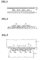
- the outer circular face of the oscillation-imparting bodies 29 and 30 are provided with circumferentially aligned protrusions 31 and 32, which extend around the oscillation-imparting body 29 or 30 at a given pitch.
- These circumferentially-aligned protrusions 31 and 32 are arranged such that, when they are placed into contact with the insulator sheet 4, they are positioned at both sides of each conductor element 5.
- the upstream horn 24 and upstream anvil 26 form, between the insulator sheets 1 and 4, the first welded portions 33 which extend along the length direction of the sheets 1 and 4 at a given pitch.
- the spaces between the first welded portions 33 are then filled with second welded portions 34 by means of the downstream horn 25 and downstream anvil 27, as shown in Fig.24.
- those zones of insulator sheets 1 and 4 which flank each conductor element 5 are sequentially welded first by the upstream horn 24 and anvil 26, then by the downstream horn 25 and anvil 27.
- the respective welded portions 33 and 34 form a continuous welded zones along the length direction of the sheets 1 and 4.
- Such a construction has the advantage of protecting the flat cable 6 from water or other contaminant penetration, and the conductor elements 5 from short-circuiting.
- the above method and means allow to form a circular rib which has alternating broad and narrow rib widths, in a very simple way.
- the obtained insulator sheets 1 and 4 procure a good adhesive force between the sheets 1 and 4, while enabling an easy peeling-off at the end portions of the sheets 4, as in the case of the first variant means.
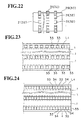
- Fig.25 shows a fifth variant embodiment of the ultrasonic welding means US, in which the same construction components as in the first variant means are referred to with the same numbers.
- the horn 36 and anvil 37 constituting an ultrasonic welding means US are respectively provided with rectangular blocks 38 and 39 on their opposing inner faces.
- the rectangular blocks 38 and 39 are placed into contact with the corresponding insulator sheets 1 and 4 at both sides of each conductor element 5.
- Each rectangular block 38 or 39 has a side line placed in parallel relation to the production flow line P, the side line having a size S.
- the space between two rectangular blocks has a corresponding side line having a size T.
- a rectangular block 38 of the horn 36 and the corresponding rectangular block 39 of the anvil 37 flank the two insulator sheets 1 and 4 and bond them by ultrasonic welding, so as to form intermittent first welded portions 33 as shown in Fig.23.
- the insulator sheets 1 and 4 are then advanced by distance T.
- the rectangular blocks 38 and 39 flank the insulator sheets 1 and 4 and bond them by ultrasonic welding, so that the troughs in the blocks formed by preceding welding are fully or partially filled with second welded portion 34.
- size S is equal to size T, the welded portions form a continuous welded line.
- the insulator sheets 1 and 4 are then moved by distance L, which corresponds to the side length of the horn 36 and anvil 37 along the production flow line P, and the same operation is repeated.
- the insulator sheets 1 and 4 are first ultrasonically welded by the rectangular blocks 38 and 39 of the corresponding horn 36 and anvil 37 at both sides of each conductor element 5 embedded in the flat cable 6.
- the insulator sheets 1 and 4 are then moved by distance T and further welded by the same method.
- the first and second welded portions 33 and 34 thus formed make a continuous welded zone.
- Such a continuous welded zone can efficiently protect the flat cable 6 from water or other conductor contaminants and the conductor elements 5 from short-circuiting, as mentioned already.
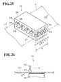
- Figs.26 to 29 show a sixth variant embodiment of the ultrasonic welding means US, in which the same construction components as in the first variant embodiment are referred to with the same reference numbers.
- the upper face of the anvil 41 in the ultrasonic welding means US forms a plane having a given side length along the production flow line P.
- the horn 42 used is the same as one shown for the fourth variant means. Namely, it comprises an oscillation-imparting body 43 having a cylindrical form. It is supported by an axis located perpendicular to the production flow line P, in a freely rotatable way. The horn 42 together with the oscillation-imparting body 43 can be freely moved back and forth along the production flow line P.
- the outer circular face of the oscillation-imparting body 43 is constructed so as to form the anvil 15 in the first variant ultrasonic welding means. Namely, it is provided with protrusions 16 aligned in the circumferential direction. These protrusions 16 are adapted to be placed into contact with the second (top-side) insulator sheet 4, at both sides of each conductor element 5.
- the horn 42 is placed over the anvil 41 at its upstream side on the production flow line P.
- the horn 42 is then moved downstream where the insulator sheets 1 and 4 are not yet welded.
- the horn 42 is moved up to the downstream end of the anvil 41, the insulator sheets 1 and 4 being ultrasonically welded along the way.
- the insulator sheets 1 and 4 are moved by a predetermined distance along the production flow line P, while the horn 42 is slightly raised. In this manner, the advancing edge of the insulator sheets 1 and 4 to be subsequently welded is positioned at the downstream end of the anvil 41.
- the horn 42 is then moved back to the upstream side of the anvil 41, while the insulator sheets 1 and 4 are ultrasonically welded by the horn 42 and anvil 41.
- the insulator sheets 1 and 4 are ultrasonically welded through a batch process, by the unit of a predetermined fraction.
- the welded portion of the flat cable 6 forms a continuous zone along the length direction of the flat cable 6.
- Such a structure has the same advantage as mentioned for the second variant means.
- the outer cylindrical face of the oscillation-imparting body 43 may be provided with the aligned protrusions 16 with the widths of the ribs varied, as in the first variant embodiment.
- the insulator sheets 1 and 4 then procures a good mechanical strength, while preserving a balanced peeling facility at the sheet end portions.
- the outer cylindrical face of the oscillation-imparting body 43 may also be configured as that of the second and third variant means of the invention.
- the horn 42 is designed as a mobile unit.
- the configuration of the horn 42 and that of the anvil 41 may be reversed in the above construction.
- the horn 42 may be configured so as to have a given length along the production flow line P
- the anvil 41 may be configured like the anvil 15 in the first, second and third variant means, which moves freely back and forth along the production flow line P.
- conductor elements 5 are embedded in a flat cable.
- the number of conductor elements is not specifically limited, and may be five or other appropriate numbers.
- a pair of insulator sheets is provisionally adhered by a hot-press procedure, and bonded then by ultrasonic welding.
- the insulator sheets can be bonded very firmly and intimately, even if the adhesive layer applied is very thin.
- the base film one constituent of the above sheet
- the adhesive layer another constituent
- the adhesive layer is so thin, its material may be the same as that for the base film, and need not comprise any halogen-containing retardant.
- the resultant flat cable is thus flame resistant, easily recyclable and generates no halogen gas upon burning.
- the thickness of one of the two insulator sheets may be at least 1.5 times that of the other sheet.
- the end portions of the manufactured flat cable may then be made into terminals which are to be inserted into connectors. To do this, only the thinner insulator sheet is stripped off, preserving the thicker insulator sheet as it is. The terminals thus prepared can be inserted easily into the connectors without being distorted.
- the ultrasonic welding means comprise a horn which imparts ultrasonic oscillations, and an anvil arranged in opposition to the horn.
- the horn has a contact plane that extends over the width of the insulator sheets and is placed into contact with one of the insulator sheets.
- the anvil has a cylindrical form that can freely rotate around an axis. This axis is arranged in a direction perpendicular to the direction of motion of the insulator sheets.
- the outer circular face of the anvil may comprise an appropriate number of arrays of continuous circular ribs or aligned protrusions arranged in the circumferential direction of the anvil, so that each circular rib or each group of aligned protrusions can be placed into contact with the insulator sheets at both sides of each conductor element.
- an upstream horn and a downstream horn may be provided at a given distance along the direction of motion of the insulator sheets, the horns imparting ultrasonic oscillations, whilst the corresponding upstream and downstream anvils are likewise provided.
- the upstream and downstream anvils comprise a contact plane with which is placed into contact one of the insulator sheets. In the this case, the anvils are installed fixedly.
- the upstream and downstream horns respectively comprise a oscillation-imparting body having a cylindrical form, the axis of which is placed perpendicularly to the moving direction of the insulator sheets.
- the oscillation-imparting bodies are held around the corresponding axes in a freely rotatable way.
- the outer circular face of the oscillation-imparting bodies may comprise an appropriate number of groups of protrusions aligned at a given interval in the circumferential direction of the cylindrical body, so that each group of aligned protrusions can be placed into contact with the insulator sheets at both sides of each conductor element.
- the upstream horn and anvil first form intermittent first welded portions, with a recess between the two welded portions.
- the downstream horn and anvil then form second welded portions filling those recesses.
- the opposing faces of the horn and anvil respectively comprise an appropriate number of groups of aligned protrusions which are arranged so as to be placed into contact with the insulator sheets at both sides of each conductor element.
- the group of aligned protrusions is formed along the direction of motion with an interval which is the same as the moving pitch of the insulator sheets.
- the groups of aligned protrusions of the horn and anvil flank the insulator sheets and form intermittent first welded portions on the latter by ultrasonic welding. The insulator sheets are then moved by the above-mentioned pitch , and the intervals between the first welded portions are bonded in the same manner.
- one of the horn and the anvil is formed into a plane having a length along the direction of motion of the insulator sheets.
- the other comprises a cylindrical body having an axis arranged perpendicularly to the direction of motion of the insulator sheets, such that the cylindrical body can rotate freely around this axis.
- the cylindrical body can further move back and forth along the direction of motion of the insulator sheets.
- the outer circular face of the cylindrical body comprises an appropriate number of continuous circular ribs which can be placed into contact with the insulator sheets at both sides of each conductor element.
- a third aspect of the invention concerns the flat cables prepared according to the methods and by the means described above.
- At least one of the insulator sheets comprises an adhesive layer at its inside face which faces the other insulator sheet (second insulator sheet).
- a plurality of conductor elements are then arranged substantially parallel to one another, and interposed between the adhesive layer and the second insulator sheet.
- the insulator sheets are subsequently pressed against each other under heat, and bonded by ultrasonic welding. By virtue of this stepwise procedure, the insulator sheets are firmly bonded, although the adhesive layer is made as thin as possible.
- the adhesive layer is made very thin, it can be made of the same type of material as the base film which contains no halogen-type retardant.
- the flat cable made thereof thus has a good flame resistance, is easily recyclable, and forms no halogen gas when burned.
- the end portions of the flat cable can be very easily made into terminals (which are to be inserted into connectors). Namely, the thinner insulator sheet is stripped off from the end portions of the flat cable, while the thicker insulator sheet is kept as it is. The terminals thus prepared can be inserted easily into the connectors, without being distorted.
- each conductor element is closed by the welded zones. Therefore, even if water or other conductor contaminants enter the flat cable, each conductor element is prevented from short-circuiting with other conductor elements.
Abstract
Description
- The invention relates to a method of manufacturing a flat electrical cable used e.g. for wiring public utility apparatuses, office automation apparatuses, electronic parts mounted in vehicles, and the like. In particular, the invention concerns devices or means used for the manufacture of such a flat cable. The invention further concerns a flat cable produced by such a manufacturing method or means.
- Figs.1A and 1B show how the prior art flat cables were manufactured in the past. According to a known method, a pair of
insulator films 100 is prepared, so that each of them comprises abase film 101 and anadhesive layer 102, the adhesive layers facing each other. A plurality ofrectangular conductors 103 are then arranged parallel to one another, and flanked by the pair ofinsulator sheets 100 over their length. Subsequently, theinsulator sheets 100 are thermally bonded e.g. by heated rollers. - In the above manufacturing method, the
adhesive layers 102 of theinsulator sheets 100 have to be sufficiently thick for each of therectangular conductors 103 to be deeply embedded in theadhesive layers 102, with theinsulator sheets 100 firmly adhered and bonded. To obtain such a result, thebase film 101 andadhesive layer 102 of eachinsulator sheet 100 must usually have an approximate thickness of 50 µm and 60 µm respectively. - In such a construction, because the
adhesive layers 102 must have substantial thickness, material costs are relatively high. In addition, as theadhesive layers 102 usually employ combustible agents, a flat cable including such a thickadhesive layer 102 raises the problem of inflammability. - Another flat cable manufacturing method is disclosed in Japanese Patent Application published under No.2000-502 833, according to which the rectangular conductors are initially arranged parallel to one another and sandwiched by two insulator sheets containing no adhesive layer, the insulator sheets being bonded to each other by ultrasonic welding.
- However, ultrasonic welding alone does not allow the insulator sheets to be sufficiently well bonded, especially in the longitudinal zones extending between the rectangular conductors contained in the flat cable. When the insulator sheets are only loosely adhered, they may form air gaps therebetween, into which water or moisture from condensation penetrate. Such a phenomenon creates a high risk of short-circuiting between the rectangular conductors.
- In parallel, research is currently underway for a flat cable which requires a smaller space and weighs less. In this case too, the flat cable is manufactured by providing two insulator sheets, and interposing between them a number of mutually parallel rectangular conductor elements over the length of the sheets. According to one of the manufacturing methods, the insulator sheets flanking the conductor elements are bonded by ultrasonic welding.
- According to one of the known ultrasonic welding methods, those side edges of insulator sheets which are positioned outside the parallel array of conductor elements are bonded intermittently by ultrasonic welding along the length direction of the sheets. However, in such a flat cable, electrically conductive material such as water tends to penetrate through non-bonded portions, thereby causing short circuits between the conductor elements.
- The present invention aims at solving the problem caused by such an accident-prone flat cable, and provides a method for its manufacture, according to which the insulator sheets are intimately and firmly adhered through an adhesive layer, and, moreover, in which the adhesive layer can be made as thin as possible.
- The invention also aims to provide a system for producing a flat cable, in which newly conceived ultrasonic welding means are used.
- Further, the invention aims at manufacturing a flat cable, in which the conductor elements are efficiently prevented from short-circuiting.
- To this end, there is provided a method of manufacturing a flat cable having a length and a width, the flat cable comprising first and second insulator sheets, and at least one adhesive layer interposed therebetween. The flat cable further comprises a plurality of conductor elements arranged in parallel relation to one another over the length of the first and second insulator sheets. The method comprises the steps of:
- providing the adhesive layer on at least the first insulator sheet so as to face the second insulator sheet;
- interposing the conductor elements between the adhesive layer and the second insulator sheets;
- provisionally adhering the first and second insulator sheets including the conductor elements through the adhesive layer by means of heat pressing force exerted from outside the first and second insulator sheets; and
- bonding, by ultrasonic welding, the first and second insulator sheets through the zones extending along the length thereof and located outside the loci where the conductor elements are arranged.
-
- Preferably, the adhesive-layer providing step comprises providing a first insulator sheet having a thickness of about 12 to about 300 µm and an adhesive layer having a thickness of about 1 to about 3 µm.
- Preferably yet, the adhesive-layer providing step comprises providing an adhesive layer formed of the same type of material as that of the first insulator sheet, the adhesive layer containing no halogen-based flame-retardant.
- Typically, the adhesive-layer providing step comprises providing the first and the second insulator sheets, so that one of them is at least about 1.5 times thicker than the other.
- The invention also proposes a system for manufacturing a flat cable having a length and a width, the flat cable comprising first and second insulator sheets, and at least one adhesive layer interposed therebetween. The flat cable further comprises a plurality of conductor elements arranged in parallel relation to one another over the length of the first and second insulator sheets. The system comprises, along a production flow line from upstream to downstream:
- means for providing the adhesive layer on at least the first insulator sheet so as to face the second insulator sheet;
- means for interposing the conductor elements between the adhesive layer and the second insulator sheets;
- means for provisionally adhering the first and second insulator sheets including the conductor elements through the adhesive layer by a heat pressing force exerted from outside the first and second insulator sheets; and
- ultrasonic welding means for bonding the first and second insulator sheets through the zones extending along the length thereof and located outside the loci where the conductor elements are arranged.
-
- Preferably, the above ultrasonic welding means comprises a horn for imparting ultrasonic oscillations, and an anvil located in opposition to the horn;
- the horn comprises an oscillation-imparting portion, with which one of the first and second insulator sheets is placed into contact;
- the anvil comprises a cylindrical form comprising an axis arranged perpendicularly to the production flow line and being freely rotatable around the axis;
- the cylindrical body comprises an outer cylindrical face including an appropriate number of arrays of protrusions, the protrusions being aligned in the circumferential direction of the outer cylindrical face and extending at a given interval therealong, such that the arrays of aligned protrusions can be placed into contact with the other of the first and second insulator sheets at both sides of each of the conductor elements. Preferably yet, the ultrasonic welding means comprises a horn for imparting ultrasonic oscillations, and an anvil located in opposition to the horn;
- the horn comprises a plane, with which one of the first and second insulator sheets is placed into contact over the width hereof;
- the anvil comprises a cylindrical form that can rotate freely around an axis, the axis being provided perpendicular to the production flow line; and
- the anvil comprises an outer circular face including an appropriate number of circular ribs continuously extending in the circumferential direction thereof, such that the circular ribs can be placed into contact with the other of the first and second insulator sheets at both sides of each of the conductor elements.
-
- Each of the circular ribs may have an alternating broad and narrow width.
- Typically, the ultrasonic welding means comprises first and second horns for imparting ultrasonic oscillations, located respectively upstream and downstream on the production flow line at a given distance, and further comprises corresponding first and second anvils located in opposition to the first and second horns;
- the first and second horns respectively include an oscillation-imparting cylindrical body, the cylindrical body comprising an axis arranged perpendicularly to the production flow line and being freely rotatable around the axis;
- each of the oscillation-imparting cylindrical bodies comprises an outer cylindrical face including an appropriate number of arrays of protrusions aligned in the circumferential direction thereof and extending at a given interval therealong, such that the arrays of protrusions can be placed into contact with one of the first and second insulator sheets at both sides of each of the conductor elements.
- the first and second anvils are fixedly positioned and respectively include a plane, with which the other of the first and second insulator sheets is placed into contact;
- whereby the first horn and anvil can form, by ultrasonic welding, a first series of bonded portions intermittent with a given interval therebetween, and the second horn and anvil then form a second series of bonded portions in the given interval.
-
- Alternatively, the ultrasonic welding means may comprise a horn for imparting ultrasonic oscillations, and an anvil located in opposition to the horn, the horn and anvil including respective planes opposing to each other;
- the opposing planes of the horn and anvil comprise respectively an appropriate number of arrays, respectively comprised of protrusions and recesses, each of the protrusions having the same gauge as each of the recesses along the length of the first and second insulator sheets, such that the arrays of the opposing face of the horn and those of the anvil can be placed into contact respectively with the first and second insulator sheets at both sides of each of the conductor elements;
- such that the first and second insulator sheets can be flanked by the arrays comprised of protrusions and recesses of the horn and of the anvil, and subjected to a first ultrasonic welding, thereby forming intermittent first bonded portions; and
- such that the first and second insulator sheets can be moved by a distance equivalent to the gauge, and the first and second insulator sheets can be further subjected to a second ultrasonic welding, thereby forming second bonded portions that link the first bonded portions.
-
- Alternatively yet, the ultrasonic welding means may comprise a horn for imparting ultrasonic oscillations, and an anvil located in opposition to said horn;
- one of the horn and the anvil has a plane with a length which extends along the length of the first and second insulator sheets, whilst the other includes a cylindrical body comprising an axis arranged perpendicularly to the production flow line and being freely rotatable around the axis, the cylindrical body being movable back and forth along the production flow line; and
- the cylindrical body comprises an outer cylindrical face including an appropriate number of circular ribs extending in the circumferential direction of the outer cylindrical face, so that the circular ribs can be placed into contact with the first and second insulator sheets at both sides of each of the conductor elements.
-
- As a variant, each of the circular ribs may have an alternating broad and narrow width, or each of the circular ribs may be provided with recesses.
- A further object of the invention is to provide a flat cable comprising first and second insulator sheets having a length and a width, and containing a plurality of conductor elements arranged in parallel relation to one another over the length of said first and second insulator sheets.
- The flat cable further comprises an adhesive layer which bonds the first insulator sheet, the second insulator sheet and the conductor elements interposed therebetween, by means of heat pressing.
- In the above flat cable, the first and second insulator sheets are bonded at the zones extending along the length thereof and located outside the loci where the conductor elements are arranged.
- As a variant, each of the zones is bonded in an intermittent way, or in a continuous way.
- Preferably, the adhesive layer comprises the same type of material as that of the first insulator sheet, the adhesive layer containing no halogen-based flame-retardant.
- Typically, one of the first insulator sheet and the second insulator sheet is at least 1.5 times thicker than the other.
- The above and the other objects, features and advantages of the present invention will be made apparent from the following description of the preferred embodiments, given as non-limiting examples, with reference to the accompanying drawings, in which:
- Figs.1A is a cross-sectional view of rectangular conductor wires interposed between two insulator films in the prior art flat cable;
- Fig.1B is a cross-sectional view of the flat cable when the insulator films are adhered;
- Fig.2 is a schematic horizontal view of a production flow line for a flat cable according to the invention;
- Fig.3 is a cross-sectional view of the rectangular conductor elements and insulator sheets at a production stage of a flat cable according to the invention;
- Fig.4 is a cross-sectional view of the rectangular conductor elements and insulator sheets at a subsequent production stage;
- Fig.5 is a cross-sectional view of the conductor elements and insulator sheets when they are bonded by ultrasonic welding;
- Fig.6 is a perspective, partially cut-away view of the resultant flat cable;
- Fig.7 is a cross-sectional view of a flat cable manufactured according to a first variant method;
- Fig.8 is a cross-sectional view of a flat cable manufactured according to a second variant method;
- Fig.9 is a perspective view of a flat cable manufactured according to a third variant method;
- Fig.10 is a cross-sectional view of a flat cable manufactured according to a fourth variant method; and
- Fig. 11 is a cross-sectional view of a flat cable manufactured according to a fifth variant method.
- Fig.12 is a side elevational view of an ultrasonic welding means according to a first variant embodiment;
- Fig.13 is an enlarged view of a horn employed in the means of Fig.12;
- Fig.14 is a left-hand side view of the horn of Fig. 13;
- Fig.15 is an enlarged elevational view of an anvil employed in the means of Fig.12;
- Fig.16 is left-hand side view of the anvil of Fig.15;
- Fig.17 is a top plan see-through view of a flat cable produced by the first variant ultrasonic welding means;
- Fig.18 is a side elevational view of the anvil contained in an ultrasonic welding means according to a second variant embodiment;
- Fig. 19 is a top plan see-through view of a flat cable produced by the second variant ultrasonic welding means;
- Fig.20 is a side elevational view of the anvil contained in an ultrasonic welding means according to a third variant embodiment;
- Fig.21 is an elevational view of an ultrasonic welding means according to a fourth variant embodiment;
- Fig.22 is a left-hand side view of an oscillation-imparting body of the ultrasonic welding unit of Fig.21;
- Fig.23 is a top plan see-through view of a flat cable partially bonded by the ultrasonic welding unit of Fig.21;
- Fig.24 is a top plan see-through view of a flat cable produced by the ultrasonic welding unit of Fig.21;
- Fig.25 is a perspective view of an ultrasonic welding means according to a fifth variant embodiment;
- Figs.26 to 29 are the views of sequential operational steps, in which a horn and an anvil are handled according to a sixth variant embodiment.
-
- Fig.2 shows a system for manufacturing a flat cable of the invention. The system comprises several means arranged along a production flow line P extending from an upstream side (left-hand side in Fig.2) to a downstream side (right-hand side in Fig.2). The production flow line P is provided, at the upstream side, with a plurality of
conductor feed rollers 10, from which are released the conductor elements 5 (e.g. conductor wires). Theconductor feed rollers 10 are followed by pitch rollers 11 which dispose theconductor elements 5 at a given pitch, and further by a pair ofsheet feed rollers press adhering means - Each
conductor feed roller 10 stores acoiled conductor wire 5 made of copper or a copper alloy. Theconductor elements 5 are provided in a number corresponding to the number of theconductor elements 5 to be arranged in parallel to each other and embedded in aflat cable 6. In the present example, fourconductor elements 5 are formed into aflat cable 6. There are therefore provided fourconductor feed rollers 10 in the production flow line P. Further, in this example, theconductor elements 5 used each have a rectangular cross-section, as shown in Fig.3. - The
conductor elements 5 drawn on the correspondingconductor feed rollers 10 are aligned parallel to one another through the pitch rollers 11, and fed into the heat-press adhering means - The
sheet feed rollers second insulator sheets 1 and 4 have a band-like shape, and are coiled and stored around the respectivesheet feed rollers - In the present embodiment, only the first insulator sheet 1 is provided with an adhesive layer. The sheet is coiled around a first
sheet feed roller 12 located below the production flow line P. Conversely, thesecond insulator sheet 4 comprising no adhesive layer. The sheet is coiled around a secondsheet feed roller 13 located above the production flow line P (shown upside down in Fig.2). The first insulator film 1 thus comprises a base film 2 and anadhesive layer 3. The base film 2 is formed of a flexible and ultrasonically fusible resin, e.g. polyethylene terephthalate (PET). One face thereof (face to be adhered to the second insulator film 4) is stuck with a thermoplastic (hot melt type)adhesive layer 3 e.g. by painting. The second insulator sheet 4 - which has no adhesive layer - just contains a base film formed of a flexible resin. Alternatively, anadhesive layer 3 may of course be provided on bothinsulator sheets 1 and 4, although their production costs become higher. The first insulator sheet 1 (with adhesive layer) and the second insulator sheet 4 (without adhesive layer) are then drawn out from thesheet feed rollers press adhering means - The heat-
press adhering means heat adhesion roller 12a located below the production flow line P and a secondheat adhesion roller 13a located above line P. The first andsecond insulator sheets 1 and 4 are superposed and introduced between the first and second heatpress adhesion rollers adhesive layer 3. - As shown in Fig.2, the
second insulator sheet 4 coiled around thesheet feed roller 13 located above the production flow line P, is then superposed from above (shown upside down in Fig.3) to theconductor elements 5 aligned in parallel, whilst the first insulator sheet 1, which is wound around thesheet feed roller 12 located below the production flow line P, is superposed from below (shown upside down in Fig.3) to thesame conductor elements 5. Theinsulator sheets 1 and 4 flanking theconductor elements 5 are then introduced between the first and secondheat adhesion rollers insulator sheets 1 and 4 wrap the alignedconductor elements 5, and are provisionally heat-adhered to each other through theheat adhesion layer 3. At the same time, theinsulator sheets 1 and 4 are firmly heat-adhered to theconductor elements 5 through the heat adhesion layer 3 (provisional adhesion step). - The provisionally heat-adhered
insulator sheets 1 and 4, which hold theconductor wires 5, are then sent to an ultrasonic bonding means US. - As shown in Figs. 2 and 5, the ultrasonic bonding means US comprises an oscillation-imparting
horn 14 located above the production flow line P, and anultrasonic anvil 17 located below the line P. - The oscillation-imparting
horn 14 comprises anoscillation imparting portion 14a made into a straight-line plane over the width of thesecond insulator sheet 4, the length of the plane being greater than the width of the sheet 4 (refer to Figs. 13 and 14 infra). The oscillation-impartingportion 14a is provided perpendicularly to the upper face of thesecond insulator sheet 4, which moves along the production flow line P, such that it can rub along over the whole width of thesecond insulator sheet 4. The ultrasonic oscillations generated by a an ultrasonic oscillation-generating mechanism e.g. oscillator, are imparted to the oscillation-impartinghorn 14. The latter 14 is configured so as to oscillate over the width of thesecond insulator sheet 4. - The
ultrasonic anvil 17 has a substantially cylindrical shape including an outer cylindrical face and anaxis 17b. The outer cylindrical face is provided with several arrays ofprotrusions 17a aligned in the circumferential direction thereof, which are to be placed into contact with the first insulator sheet 1. Each array of protrusions is configured so as to surround the cylindrical face at a given pitch in the circumferential direction, defining a toothed wheel shape, such that the positions of those arrays ofprotrusions 17a correspond to the spaces between the parallel-alignedconductor elements 5, as well as to the two side edges of the first insulator sheet 1. Theaxis 17b of theultrasonic anvil 17 is placed perpendicularly to the production flow line P, at a position below it. Theultrasonic anvil 17 is held around theaxis 17b in a freely rotatable way. When the first insulator film 1 is forwarded along the production flow line P, the arrays of protrusions17a formed on the outer cylindrical face of the ultrasonic anvil are pressed onto the external face (bottom face) of the first insulator film 1. Accordingly, as the first insulator film 1 advances, the ultrasonic anvil rotates in synchronization with its advancement, by frictional dragging effect or by being driven by a rotation driver (not shown in figures). - When the
insulator films 1 and 4 holding a plurality ofconductor elements 5 are heat pressed and introduced between the oscillation-impartinghorn 14 and theultrasonic anvil 17, the oscillation-impartingportion 14a of thehorn 14 rubs against the external face (top face) of thesecond insulator sheet 4 over the entire width thereof. At the same time, the arrays ofprotrusions 17a of theultrasonic anvil 17 are placed under the oscillation-impartingportion 14a, and placed into contact with the external face of the first insulator sheet 1. The ultrasonic oscillation energy is imparted to theinsulator sheets 1 and 4, while the latter are pressed against each other. As shown in Fig.6, theinsulator sheets 1 and 4 are bonded by ultrasonic welding in the zones extending circumferentially outside the parallel-alignedconductor elements 5. As theinsulator sheets 1 and 4 move on, the oscillation-impartingportion 14a of the oscillation-impartinghorn 14 rubs against the external face of thesecond insulator sheet 4, whilst the arrays ofprotrusions 17a of theultrasonic anvil 17 are intermittently and sequentially placed into contact with the external face of the first insulator sheet 1. Theinsulator sheets 1 and 4 are thus bonded by ultrasonic welding through intermittent loci extending along the longitudinal direction of the insulator sheets 1 and 4 (ultrasonic welding step). - Finally, the two side edges of the
insulator sheets 1 and 4 are cut off byblades 18. The resultingflat cable 6 is then wound around a coilingroll 20. - According to the above production steps, the
conductor elements 5 are arranged parallel to one another, and interposed between theinsulator sheets 1 and 4. The latter are first heat pressed against each other, and then bonded by ultrasonic welding to form aflat cable 6. - In the
flat cable 6 thus produced, theinsulator sheets 1 and 4 are bonded by ultrasonic welding in the zones outside the loci where theconductor elements 5 are arranged in parallel, so that theinsulator sheets 1 and 4 can be bonded with a sufficient bonding force. Moreover, the bonding is effected by ultrasonic spot welding through loci S, so that, when theflat cable 6 is to be parted or peeled, theinsulator sheets 1 and 4 can be easily separated from each other. - As the
insulator sheets 1 and 4 are press-adhered under heat prior to ultrasonic welding, byheat adhesion rollers insulator sheets 1 and 4 are firmly and intimately adhered, avoiding the formation of air gaps. Moreover, as the insulator sheet 1 and theconductor elements 5 are adhered through theadhesive layer 3, theseconductor elements 5 cannot be displaced easily from the positions where they are fixed by theinsulator sheets 1 and 4. - Further, the ultrasonic welding produces a strong adhesive force between the
insulator sheets 1 and 4. Theadhesive layer 3 therefore only needs to be thick enough to secure the adhesion between theinsulator sheets 1 and 4. The thickness of theadhesive layer 3 can thus be reduced to a minimum, compared to the prior art example shown in Figs.1A and 1B. - In practice, when the base film 2 of the insulator sheet 1 has a thickness of 12 to 300 µm, preferably 25 to 100 µm, the
adhesive layer 3 may have a thickness of 1 to 3 µm. - As the
adhesive layer 3 can be made thinner than in the prior art, use of inflammable adhesive agents can be reduced to a minimum, and theflat cable 6 thus manufactured procures a good flame resistance. - In the prior art example shown in Figs.1A and 1B, the adhesive layer contains a halogen-containing flame retardant in order to procure a sufficient resistance to flame. When such adhesive layers are scrapped, they generate halogen gas and raise environmental problems. By contrast, the present manufacturing method already confers to the flat cable 6 a good flame resistance, and allows using an adhesive agent containing no halogen compound. In addition, the inventive
adhesive layer 3 can be made of an adhesive agent having the same type of material as that of the base film 2. Recycling processes offlat cables 6 can thus be greatly simplified. Examples of such an insulator sheet 1 include one in which the base film 2 is made of a polyester-type resin e.g. polyethylene terephthalate (PET) and polybutylene terephthalate (PBT), whilst theadhesive layer 3 is made of a polyester-type adhesive agent e.g. polyester elastomer. In another example, the base film 2 is formed of a polyolefin-type resin, e.g. polyethylene, whilst theadhesive layer 3 is formed of a polyolefin-type adhesive agent, e.g. ethylene-vinyl acetate polymer (EVA). In above cases, the base film 2 and theadhesive layer 3 can be treated as similar material, and recycled and regenerated in a same handling way. - In variant embodiments described infra, the component elements corresponding to those already mentioned in the preceding embodiment are referred to with the same reference numbers. Only the new elements are explained specifically.
- In a first variant embodiment of a first aspect of the invention (Fig.7), a
transparent insulator sheet 4B containing no adhesive layer is used as thesecond insulator sheet 4, thetransparent insulator film 4B being formed of a transparent resin such as polyethylene terephthalate (PET), 1-(N-phenylamino)naphthalene (PA), polycarbonate (PC), etc.. - In the prior art case shown in Figs.1A and 1B, both
insulator sheets 100 contain a respectiveadhesive layer 102. Theinsulator sheets 100 thus constructed tend to become opaque, typically because of the non-transparency of the adhesive layers 102. By comparison, the present invention enables to use thesecond insulator sheet 4 free of adhesive layer. Accordingly, this embodiment makes it much easier to create atransparent insulator sheet 4B merely by using a transparent resin and doing away with adhesive layer. - When the
transparent insulator sheet 4B is used, the state of the inner zone comprised between theinsulator sheets 1 and 4B can be observed directly from outside, through thetransparent insulator sheet 4B. Undesirable inclusions, irregularities of the conductor elements and the like can thus be detected easily. Further, the front side and reverse side of the manufacturedflat cable 6B can be easily recognized. As a result, for eachflat cable 6B, the connecting points at both ends of eachconductor element 5 can be observed very easily. - In a second variant method (see Fig.8), the first insulator sheet 1, comprising an adhesive layer in the above embodiments, is further coated with a thermoplastic adhesive layer over its external face (first external
adhesive layer 51C), so as to form a first coated insulator sheet 1C. Typically, thesecond insulator sheet 4, which comprises no adhesive layer in the preceding embodiments, is also coated with a thermoplastic adhesive layer over its external face (second external adhesive layer), so as to form a secondcoated insulator sheet 4C. When the heat-press adhesion is performed, theadhesive layer 3 between thecoated insulator sheets 1C and 4C is melted down and does not appear beside the conductor elements 5 (see Fig.8). - When the
flat cable 6C thus prepared is fitted into counter-part fitting means, e.g. a connector box in an apparatus, it can easily be fitted with the fitting means through the externaladhesive layers - In the preceding embodiment, when the
coated insulator sheets 1C and 4C are thermally adhered, the externaladhesive layers adhesive layer 3. Such a situation can be avoided by finishing the outer cylindrical face of theheat rollers adhesive layers heat rollers adhesive layers adhesive layer 3 for bonding theinsulator sheets 1C and 4C. - In a third variant shown in Fig.9, the thickness h1 of the insulator sheet 4D, which corresponds to the
insulator sheet 4 without adhesive layer in the first embodiment, may be set to be at least 1.5 times the thickness h2 of the base film of theinsulator sheet 1D, which corresponds to the insulator sheet 1 with adhesive layer in the first embodiment. Alternatively, the thickness h2 may be at least 1.5 times the thickness h1. - In such a configuration, when the end portions of the finished
flat cable 6D are made into terminals to be inserted into connectors, only the thinner insulator sheet, e.g. thefirst insulator sheet 1D, needs to be stripped off at the end portions, while the thicker insulator sheet 4D may be left as it stands. In such a case, the end portions of theflat cable 6D, though not reinforced by a supporting plate, may be made into terminals, the latter being sufficiently resistant to bending when inserted into connectors. - In a fourth variant shown in Fig. 10, the width of the
insulator sheet 4E, which corresponds to theinsulator film 4 in the first embodiment, is set to be greater than that of theinsulator sheet 1E, which corresponds to the insulator sheet 1 in the first embodiment. When bothinsulator sheets insulator sheet 4E extend outwardly, are bent upwardly (when viewed in Fig.10), and superposed over the corresponding two side edges of theinsulator sheet 1E. The corresponding side edges are then bonded through e.g. the thermoplastic adhesive agent, thereby forming aflat cable 6E. - In the above case, both side edges of the
flat cable 6E form a smooth rounded edge, which has advantages of giving a soft touch feeling and also facilitating handling. Further, the side edges of theflat cable 6E are strengthened by the side edges 4Ea of theinsulator sheet 4E, so that theflat cable 6E becomes more resistant to torsional stress. Furthermore, the end portions of theflat cable 6E will not be distorted when inserted into connectors. - In a
flat cable 6F of a fifth variant (Fig.11),insulator sheets 1F and 4F may be made slightly wider than theinsulator sheets 1 and 4 of the first embodiment, and joined slightly biased to each other in their width direction. A side edge 1Fa of e.g. the insulator sheet 1F, which hangs over the corresponding side edge of theinsulator sheet 4F, may then be bent downwardly (as viewed in Fig.11) and superposed on the latter 4F. They may be then bonded by means of a thermoplastic adhesive agent. A side edge 4Fa of theinsulator sheet 4F may be processed likewise, and adhered to the insulator sheet 1F. - Such a structure confers the
flat cable 6F with the same effect as in the fourth variant case shown in Fig.10. Moreover, as theinsulator sheets 1F and 4F may have the same width, the number of component elements can be reduced, and manufacturing costs can be lowered. - A second aspect of the invention generally pertains to the ultrasonic welding means employed in the production flow line P mentioned for the first aspect of the invention.
- In the first aspect of the invention, the anvil used carries a plurality of arrays of protrusions aligned on its cylindrical face. By contrast, the anvil mentioned hereafter is designed to form a plurality of continuous circular ribs, while preserving the possibility of varying the width of the ribs along the circumferential direction.
- As shown in Figs. 12 and 15, the
anvil 15 of a first variant ultrasonic welding means also has a substantially cylindrical form, theaxis 15a of which is biased downwardly from the production flow line P, and positioned perpendicularly thereto. Theanvil 15 is freely rotatable around thecylinder axis 15a. The outer cylindrical face of theanvil 15 carries severalcircular ribs 16, each of which extends along the circumferential direction, while alternating the size of the rib width. To this end, eachcircular rib 16 is provided with an alternatingwide rib portion 16a andnarrow rib portion 16b, at a given pitch along the circular direction. Further, thecircular ribs 16 are arranged widthwise, so that they are positioned between the conductor elements on the one hand, and at the two side edges of the sheets on the other, when these sheets are passed through. - When the
insulator sheets 1 and 4 are forwarded along the production flow line P, thecircular ribs 16 are placed into contact with the insulator sheet 1 located below the production flow line P. Theanvil 15 is thus rotated through dragging, or can be rotated by a driving means (not shown in the figures) in synchronization with the supply speed of the insulator sheets 1. - The
insulator sheets 1 and 4 including theconductor elements 5 are thus sent between thehorn 14 and theanvil 15, while thehorn 14 is imparted with ultrasonic oscillations. Accordingly, the oscillation-impartingportion 14a of the horn 14 (shown in Figs.13 and 14) rubs against over the whole width of theinsulator sheet 4 located above the production flow line P, while thecircular ribs 16 of theanvil 15 are placed right beneath the oscillation-impartingportion 14a and placed into contact with the insulator sheet 1 located below the production flow line P. In this state, thecircular ribs 16 are placed outside the zones where theconductor elements 5 are arranged in the flat cable. Thereafter, theinsulator sheets 1 and 4 are first adhered under pressure. Ultrasonic oscillation energy is then imparted to theinsulator sheets 1 and 4, and the latter are bonded through welding (Fig.17). - As the
insulator sheets 1 and 4 move on, the oscillation-impartingportion 14a of thehorn 14 rubs along the outer face of theinsulator sheet 4 located above the production flow line P. Simultaneously, thecircular ribs 16 of theanvil 15 are placed into contact with the outer face of the insulator sheet 1 located below the production flow line P. Theinsulator sheets 1 and 4 are thus continuously bonded by ultrasonic welding along the length direction of thesheets 1 and 4. - A
flat cable 6 thus formed by welding is sent to aguide roller 19, and wound around a coilingroll 20. - According to the above method comprising stepwise manufacturing means, the
insulator sheets 1 and 4 of theflat cable 6 are continuously welded at both sides of eachconductor element 5 along the length direction of thesheets 1 and 4. An additional advantage of the first variant embodiment is that, even when electro-conductive contaminants e.g. water enter into theflat cable 6, each conductor element is efficiently prevented from short-circuiting with another conductor element 1 by intercalating continuous weld-bonding. - As shown in Fig.17, the ultrasonically welded
zone 21 includes wide welded portions and narrow welded portions. Theinsulator sheets 1 and 4 thus bonded are firmly adhered to each other, while preserving the feature that thesesheets 1 and 4 can be easily detached at their end portions. This is a noteworthy advantage compared to a structure in which the welded zone has a wide welded portion all along the sheet length. - By comparison, Fig.18 shows a second variant ultrasonic welding means, in which the
circular ribs 16 of theanvil 15 are provided with the same width all along the circumferential direction of theribs 16. The other constructional elements are the same as in the first variant embodiment. - As shown in Fig.19, the
flat cable 6 according to the second variant means comprises a weldedzone 21 having the same width over the length direction of theflat cable 6. As in the first variant means, even when water or other electro-conductive contaminants enter into theflat cable 6, each conductor element is efficiently prevented from short-circuiting with another conductor element 1 by intercalating continuously welded bonds. - Fig.20 shows a third variant ultrasonic welding means, in which the
circular ribs 16 of theanvil 15 have the same width along the circumferential direction of theribs 16, as in the second variant means. However, thecircular ribs 16 are provided withrecesses 16c at a given pitch along the circumferential direction. The pitch between therecesses 16c may be chosen as a function of a balance desired to be established between the adhesion strength and the peeling facility. The other construction components are the same as in the first variant means. - The
flat cable 6 produced in the third variant means comprises weldedzones 21 having varying welded surfaces along their length, and produces the same effect as in the first variant means. - Fig.21 shows a fourth variant ultrasonic welding means of the invention, in which the same construction components are referred to with the same references as in the first variant means of the invention.
- In this embodiment, the ultrasonic welding means US comprises an
upstream horn 24 and a downstream horn 25 (located at a given distance downstream along the production flow line P), respectively imparting ultrasonic oscillations to theinsulator sheets 1 and 4. The ultrasonic welding means US further comprises a correspondingupstream anvil 26 anddownstream anvil 27. - The
upstream anvil 26 and thedownstream anvil 27 are fixedly installed, and include respectively a plane top face which is placed into contact with the insulator sheet 1 located below the production flow line P. - The
upstream horn 24 and thedownstream horn 25 comprise corresponding oscillation-impartingbodies axes - As shown in Fig.22, the outer circular face of the oscillation-imparting
bodies protrusions body protrusions insulator sheet 4, they are positioned at both sides of eachconductor element 5. - As shown in Fig.23, the
upstream horn 24 andupstream anvil 26 form, between theinsulator sheets 1 and 4, the first weldedportions 33 which extend along the length direction of thesheets 1 and 4 at a given pitch. The spaces between the first weldedportions 33 are then filled with second weldedportions 34 by means of thedownstream horn 25 anddownstream anvil 27, as shown in Fig.24. - According to the above method and means, those zones of
insulator sheets 1 and 4 which flank eachconductor element 5 are sequentially welded first by theupstream horn 24 andanvil 26, then by thedownstream horn 25 andanvil 27. The respective weldedportions sheets 1 and 4. Such a construction has the advantage of protecting theflat cable 6 from water or other contaminant penetration, and theconductor elements 5 from short-circuiting. Further, the above method and means allow to form a circular rib which has alternating broad and narrow rib widths, in a very simple way. - More particularly, when the
protrusions 31 of a first oscillation-impartingbody 29 have a wider size, whilst theprotrusions 32 of a second oscillation-impartingbody 30 have a narrower size, the obtainedinsulator sheets 1 and 4 procure a good adhesive force between thesheets 1 and 4, while enabling an easy peeling-off at the end portions of thesheets 4, as in the case of the first variant means. - Fig.25 shows a fifth variant embodiment of the ultrasonic welding means US, in which the same construction components as in the first variant means are referred to with the same numbers.
- In this embodiment, the
horn 36 andanvil 37 constituting an ultrasonic welding means US are respectively provided withrectangular blocks corresponding insulator sheets 1 and 4 at both sides of eachconductor element 5. Eachrectangular block - A
rectangular block 38 of thehorn 36 and the correspondingrectangular block 39 of theanvil 37 flank the twoinsulator sheets 1 and 4 and bond them by ultrasonic welding, so as to form intermittent first weldedportions 33 as shown in Fig.23. Theinsulator sheets 1 and 4 are then advanced by distance T. Subsequently, therectangular blocks insulator sheets 1 and 4 and bond them by ultrasonic welding, so that the troughs in the blocks formed by preceding welding are fully or partially filled with second weldedportion 34. When size S is equal to size T, the welded portions form a continuous welded line. - The
insulator sheets 1 and 4 are then moved by distance L, which corresponds to the side length of thehorn 36 andanvil 37 along the production flow line P, and the same operation is repeated. - More particularly, the
insulator sheets 1 and 4 are first ultrasonically welded by therectangular blocks horn 36 andanvil 37 at both sides of eachconductor element 5 embedded in theflat cable 6. Theinsulator sheets 1 and 4 are then moved by distance T and further welded by the same method. The first and second weldedportions flat cable 6 from water or other conductor contaminants and theconductor elements 5 from short-circuiting, as mentioned already. - Figs.26 to 29 show a sixth variant embodiment of the ultrasonic welding means US, in which the same construction components as in the first variant embodiment are referred to with the same reference numbers.
- In this embodiment, the upper face of the
anvil 41 in the ultrasonic welding means US forms a plane having a given side length along the production flow line P. On the other hand, thehorn 42 used is the same as one shown for the fourth variant means. Namely, it comprises an oscillation-impartingbody 43 having a cylindrical form. It is supported by an axis located perpendicular to the production flow line P, in a freely rotatable way. Thehorn 42 together with the oscillation-impartingbody 43 can be freely moved back and forth along the production flow line P. - The outer circular face of the oscillation-imparting
body 43 is constructed so as to form theanvil 15 in the first variant ultrasonic welding means. Namely, it is provided withprotrusions 16 aligned in the circumferential direction. Theseprotrusions 16 are adapted to be placed into contact with the second (top-side)insulator sheet 4, at both sides of eachconductor element 5. - As shown in Fig.26, the
horn 42 is placed over theanvil 41 at its upstream side on the production flow line P. Thehorn 42 is then moved downstream where theinsulator sheets 1 and 4 are not yet welded. - As shown in Fig.27, the
horn 42 is moved up to the downstream end of theanvil 41, theinsulator sheets 1 and 4 being ultrasonically welded along the way. - As shown in Fig.28, the
insulator sheets 1 and 4 are moved by a predetermined distance along the production flow line P, while thehorn 42 is slightly raised. In this manner, the advancing edge of theinsulator sheets 1 and 4 to be subsequently welded is positioned at the downstream end of theanvil 41. - As illustrated in Fig.29, the
horn 42 is then moved back to the upstream side of theanvil 41, while theinsulator sheets 1 and 4 are ultrasonically welded by thehorn 42 andanvil 41. - By repeating the above procedure, the
insulator sheets 1 and 4 are ultrasonically welded through a batch process, by the unit of a predetermined fraction. - According to the present embodiment, the welded portion of the
flat cable 6 forms a continuous zone along the length direction of theflat cable 6. Such a structure has the same advantage as mentioned for the second variant means. - Moreover, the outer cylindrical face of the oscillation-imparting
body 43 may be provided with the alignedprotrusions 16 with the widths of the ribs varied, as in the first variant embodiment. Theinsulator sheets 1 and 4 then procures a good mechanical strength, while preserving a balanced peeling facility at the sheet end portions. - Alternatively, the outer cylindrical face of the oscillation-imparting
body 43 may also be configured as that of the second and third variant means of the invention. - In the above sixth ultrasonic welding means, the
horn 42 is designed as a mobile unit. However, the configuration of thehorn 42 and that of theanvil 41 may be reversed in the above construction. Namely, thehorn 42 may be configured so as to have a given length along the production flow line P, whilst theanvil 41 may be configured like theanvil 15 in the first, second and third variant means, which moves freely back and forth along the production flow line P. - In each of the above embodiments, four
conductor elements 5 are embedded in a flat cable. However, the number of conductor elements is not specifically limited, and may be five or other appropriate numbers. - As can be understood from the inventive method described above (first aspect of the invention), a pair of insulator sheets is provisionally adhered by a hot-press procedure, and bonded then by ultrasonic welding. As a result, the insulator sheets can be bonded very firmly and intimately, even if the adhesive layer applied is very thin.
- When manufacturing an insulator sheet coated with an adhesive layer by applying the above method, the base film (one constituent of the above sheet) may be 12 to 300 µm thick, whilst the adhesive layer (another constituent) may be as thin as 1 to 3 µm.
- As the adhesive layer is so thin, its material may be the same as that for the base film, and need not comprise any halogen-containing retardant. The resultant flat cable is thus flame resistant, easily recyclable and generates no halogen gas upon burning.
- Further, the thickness of one of the two insulator sheets (measured for the base film, as the case may be) may be at least 1.5 times that of the other sheet. The end portions of the manufactured flat cable may then be made into terminals which are to be inserted into connectors. To do this, only the thinner insulator sheet is stripped off, preserving the thicker insulator sheet as it is. The terminals thus prepared can be inserted easily into the connectors without being distorted.
- The ultrasonic welding means comprise a horn which imparts ultrasonic oscillations, and an anvil arranged in opposition to the horn. The horn has a contact plane that extends over the width of the insulator sheets and is placed into contact with one of the insulator sheets. The anvil has a cylindrical form that can freely rotate around an axis. This axis is arranged in a direction perpendicular to the direction of motion of the insulator sheets. The outer circular face of the anvil may comprise an appropriate number of arrays of continuous circular ribs or aligned protrusions arranged in the circumferential direction of the anvil, so that each circular rib or each group of aligned protrusions can be placed into contact with the insulator sheets at both sides of each conductor element.
- In another ultrasonic welding means, an upstream horn and a downstream horn may be provided at a given distance along the direction of motion of the insulator sheets, the horns imparting ultrasonic oscillations, whilst the corresponding upstream and downstream anvils are likewise provided. The upstream and downstream anvils comprise a contact plane with which is placed into contact one of the insulator sheets. In the this case, the anvils are installed fixedly. The upstream and downstream horns respectively comprise a oscillation-imparting body having a cylindrical form, the axis of which is placed perpendicularly to the moving direction of the insulator sheets. The oscillation-imparting bodies are held around the corresponding axes in a freely rotatable way. The outer circular face of the oscillation-imparting bodies may comprise an appropriate number of groups of protrusions aligned at a given interval in the circumferential direction of the cylindrical body, so that each group of aligned protrusions can be placed into contact with the insulator sheets at both sides of each conductor element. The upstream horn and anvil first form intermittent first welded portions, with a recess between the two welded portions. The downstream horn and anvil then form second welded portions filling those recesses.
- In another ultrasonic welding means, the opposing faces of the horn and anvil respectively comprise an appropriate number of groups of aligned protrusions which are arranged so as to be placed into contact with the insulator sheets at both sides of each conductor element. The group of aligned protrusions is formed along the direction of motion with an interval which is the same as the moving pitch of the insulator sheets. The groups of aligned protrusions of the horn and anvil flank the insulator sheets and form intermittent first welded portions on the latter by ultrasonic welding. The insulator sheets are then moved by the above-mentioned pitch , and the intervals between the first welded portions are bonded in the same manner.
- In yet another ultrasonic welding means, one of the horn and the anvil is formed into a plane having a length along the direction of motion of the insulator sheets. The other comprises a cylindrical body having an axis arranged perpendicularly to the direction of motion of the insulator sheets, such that the cylindrical body can rotate freely around this axis. The cylindrical body can further move back and forth along the direction of motion of the insulator sheets. The outer circular face of the cylindrical body comprises an appropriate number of continuous circular ribs which can be placed into contact with the insulator sheets at both sides of each conductor element.
- A third aspect of the invention concerns the flat cables prepared according to the methods and by the means described above.
- In the flat cable thus prepared, at least one of the insulator sheets (first insulator sheet) comprises an adhesive layer at its inside face which faces the other insulator sheet (second insulator sheet). A plurality of conductor elements are then arranged substantially parallel to one another, and interposed between the adhesive layer and the second insulator sheet. The insulator sheets are subsequently pressed against each other under heat, and bonded by ultrasonic welding. By virtue of this stepwise procedure, the insulator sheets are firmly bonded, although the adhesive layer is made as thin as possible.
- As the adhesive layer is made very thin, it can be made of the same type of material as the base film which contains no halogen-type retardant. The flat cable made thereof thus has a good flame resistance, is easily recyclable, and forms no halogen gas when burned.
- When one of the insulator sheets has a thickness greater than 1.5 times that of the other insulator film (measured for the base film, as the case may be), the end portions of the flat cable can be very easily made into terminals (which are to be inserted into connectors). Namely, the thinner insulator sheet is stripped off from the end portions of the flat cable, while the thicker insulator sheet is kept as it is. The terminals thus prepared can be inserted easily into the connectors, without being distorted.
- In the flat cable thus prepared, both sides of each conductor element is closed by the welded zones. Therefore, even if water or other conductor contaminants enter the flat cable, each conductor element is prevented from short-circuiting with other conductor elements.
Claims (18)
- A method of manufacturing a flat cable (6) having a length and a width, the flat cable (6) comprising first and second insulator sheets (1, 4), and at least one adhesive layer (3) interposed therebetween, the flat cable (6) further comprising a plurality of conductor elements (5) arranged in parallel relation to one another over the length of the first and second insulator sheets (1, 4), characterised in that said method comprises the steps of:providing said adhesive layer (3) on at least said first insulator sheet (1) so as to face said second insulator sheet (4);interposing said conductor elements (5) between said adhesive layer (3) and said second insulator sheets (4);provisionally adhering said first and second insulator sheets (1, 4) including said conductor elements (5) through said adhesive layer (3) by means of heat pressing force exerted from outside said first and second insulator sheets (1, 4); andbonding, by ultrasonic welding, said first and second insulator sheets (1, 4) through the zones extending along said length thereof and located outside the loci where said conductor elements (5) are arranged.
- The method according to claim 1, wherein said adhesive-layer providing step comprises providing a first insulator sheet (1) having a thickness of about 12 to about 300 µm and an adhesive layer (3) having a thickness of 1 about to about 3 µm.
- The method according to claim 1 or 2, wherein said adhesive-layer providing step comprises providing an adhesive layer (3) formed of the same type of material as that of said first insulator sheet (1), said adhesive layer containing no halogen-based flame-retardant.
- The method according to any one of claims 1 to 3, wherein said adhesive-layer providing step comprises providing said first and said second insulator sheets (1, 4), so that one of said sheets (1, 4) is at least about 1.5 times thicker than the other.
- A system for manufacturing a flat cable (6) having a length and a width, the flat cable (6) comprising first and second insulator sheets (1, 4), and at least one adhesive layer (3) interposed therebetween, the flat cable (6) further comprising a plurality of conductor elements (5) arranged in parallel relation to one another over the length of the first and second insulator sheets (1, 4), characterised in that said system comprises, along a production flow line (P) from upstream to downstream:means for providing said adhesive layer (3) on at least said first insulator sheet (1) so as to face said second insulator sheet (4);means for interposing said conductor elements (5) between said adhesive layer (3) and said second insulator sheet (4);means for provisionally adhering said first and second insulator sheets (1, 4) including said conductor elements (5) through said adhesive layer (3) by a heat pressing force exerted from outside said first and second insulator sheets (1, 4); andultrasonic welding means (US) for bonding said first and second insulator sheets (1, 4) through the zones extending along said length thereof and located outside the loci where said conductor elements (5) are arranged.
- The system according to claim 5, wherein said ultrasonic welding means (US) comprises a horn (14) for imparting ultrasonic oscillations, and an anvil (17) located in opposition to said horn (14);said horn (14) comprises an oscillation-imparting portion, with which one of said first and second insulator sheets (1, 4) is placed into contact;said anvil (17) comprises a cylindrical form comprising an axis (17b) arranged perpendicularly to said production flow line (P) and being freely rotatable around said axis (17b);said cylindrical form comprises an outer cylindrical face including an appropriate number of arrays of protrusions (17a), said protrusions (17a) being aligned in the circumferential direction of said outer cylindrical face and extending at a given interval therealong, such that said arrays of aligned protrusions (17a) can be placed into contact with the other of said first and second insulator sheets (1, 4) at both sides of each of said conductor elements (5).
- The system according to claim 5, wherein said ultrasonic welding means (US) comprises a horn (14) for imparting ultrasonic oscillations, and an anvil (15) located in opposition to said horn (14);said horn (14) comprises a plane (14a), with which one of said first and second insulator sheets (1, 4) is placed into contact over said width hereof;said anvil (15) comprises a cylindrical form that can rotate freely around an axis (15a), said axis (15a) being provided perpendicular to said production flow line (P); andsaid anvil (15) comprises an outer circular face including an appropriate number of circular ribs (16) continuously extending in the circumferential direction thereof, such that said circular ribs (16) can be placed into contact with the other of said first and second insulator sheets (1, 4) at both sides of each of said conductor elements (5).
- The system according to claim 7, wherein each of said circular ribs (16) has an alternating broad and narrow width (16a, 16b).
- The system according to claim 5, wherein said ultrasonic welding means (US) comprises first and second horns (24, 25) for imparting ultrasonic oscillations, located respectively upstream and downstream on said production flow line (P) at a given distance, and further comprises corresponding first and second anvils (26, 27) located in opposition to said first and second horns (24, 25);said first and second horns (24, 25) respectively include an oscillation-imparting cylindrical body (29, 30), said cylindrical body (29, 30) comprising an axis (29a, 30a) arranged perpendicularly to said production flow line (P) and being freely rotatable around said axis (29a, 30a);each of said oscillation-imparting cylindrical bodies (29, 30) comprises an outer cylindrical face including an appropriate number of arrays of protrusions (31, 32) aligned in the circumferential direction thereof and extending at a given interval therealong, such that said arrays of protrusions (31, 32) can be placed into contact with one of said first and second insulator sheets (1, 4) at both sides of each of said conductor elements (5).said first and second anvils (26, 27) are fixedly positioned and respectively include a plane, with which the other of said first and second insulator sheets (1, 4) is placed into contact;whereby said first horn (24) and anvil (26) are adapted to form, by ultrasonic welding, a first series of bonded portions (33) intermittent with a given interval therebetween, and said second horn (25) and anvil (27) then form a second series of bonded portions (34) in said given interval.
- The system according to claim 5, wherein said ultrasonic welding (US) means comprises a horn (36) for imparting ultrasonic oscillations, and an anvil (37) located in opposition to said horn, said horn (36) and anvil (37) including respective planes opposing to each other;said opposing planes of said horn (36) and anvil (37) comprise respectively an appropriate number of arrays, respectively comprised of protrusions (38, 39) and recesses, each of said protrusions (38, 39) has the same gauge (S) as each of said recess (T) along the length of said first and second insulator sheets (1, 4), such that said arrays of said opposing face of said horn (36) and those of said anvil (37) can be placed into contact respectively with said first and second insulator sheets (1, 4) at both sides of each of said conductor elements (5);such that said first and second insulator sheets (1, 4) can be flanked by said arrays comprised of protrusions (38, 39) and recesses of said horn (36) and of said anvil (37), and subjected to a first ultrasonic welding, thereby forming intermittent first bonded portions; andsuch that said first and second insulator sheets (1, 4) can be moved by a distance equivalent to said gauge (T), and said first and second insulator sheets (1, 4) can be further subjected to a second ultrasonic welding, thereby forming second bonded portions that link said first bonded portions.
- The system according to claim 5, wherein said ultrasonic welding means (US) comprises a horn (41) for imparting ultrasonic oscillations, and an anvil (42) located in opposition to said horn (41);one of said horn (41) and said anvil (42) has a plane with a length which extends along said length of said first and second insulator sheets (1, 4), whilst the other includes a cylindrical body (43) comprising an axis arranged perpendicularly to said production flow line (P) and being freely rotatable around said axis, said cylindrical body (43) being movable back and forth along said production flow line; andsaid cylindrical body (43) comprises an outer cylindrical face including an appropriate number of circular ribs extending in the circumferential direction of said outer cylindrical face, so that said circular ribs can be placed into contact with said first and second insulator sheets (1, 4) at both sides of each of said conductor elements (5).
- The system according to claim 11, wherein each of said circular ribs has an alternating broad and narrow width.
- The system according to claim 11, wherein each of said circular ribs is provided with recesses.
- A flat cable (6) comprising first and second insulator sheets (1, 4) having a length and a width, and containing a plurality of conductor elements (5) arranged in parallel relation to one another over the length of said first and second insulator sheets (1, 4);said flat cable (6) further comprising an adhesive layer (3) which bonds said first insulator sheet (1), said second insulator sheet (4) and said conductor elements (5) interposed therebetween, by means of heat-pressing;said first and second insulator sheets (1, 4) being bonded in the zones extending along said length thereof and located outside the loci where said conductor elements (5) are arranged.
- The flat cable (6) according to claim 14, wherein each of said zones is bonded in an intermittent way.
- The flat cable (6) according to claim 14, wherein each of said zones is bonded in a continuous way.
- The flat cable (6) according to any one of claims 14 to 16, wherein said adhesive layer (3) comprises the same type of material as that of said first insulator sheet (1), said adhesive layer (3) containing no halogen-based flame-retardant.
- The flat cable (6) according to any one of claims 14 to 17, wherein one of said first insulator sheet (1) and said second insulator sheet (4) is at least 1.5 times thicker than the other.
Applications Claiming Priority (4)
| Application Number | Priority Date | Filing Date | Title |
|---|---|---|---|
| JP2000209759 | 2000-07-11 | ||
| JP2000209759A JP3752973B2 (en) | 2000-07-11 | 2000-07-11 | Flat cable manufacturing method and flat cable |
| JP2000244711A JP3893859B2 (en) | 2000-08-11 | 2000-08-11 | Flat cable manufacturing equipment |
| JP2000244711 | 2000-08-11 |
Publications (3)
| Publication Number | Publication Date |
|---|---|
| EP1172826A2 true EP1172826A2 (en) | 2002-01-16 |
| EP1172826A3 EP1172826A3 (en) | 2003-01-29 |
| EP1172826B1 EP1172826B1 (en) | 2008-10-15 |
Family
ID=26595794
Family Applications (1)
| Application Number | Title | Priority Date | Filing Date |
|---|---|---|---|
| EP01401846A Expired - Lifetime EP1172826B1 (en) | 2000-07-11 | 2001-07-10 | Flat cable, apparatus and its manufacturing method |
Country Status (3)
| Country | Link |
|---|---|
| US (2) | US6585836B2 (en) |
| EP (1) | EP1172826B1 (en) |
| DE (1) | DE60136134D1 (en) |
Cited By (1)
| Publication number | Priority date | Publication date | Assignee | Title |
|---|---|---|---|---|
| EP2720233A3 (en) * | 2012-10-09 | 2016-09-07 | SUMIDA flexible connections GmbH | Flat conductor strip cable |
Families Citing this family (23)
| Publication number | Priority date | Publication date | Assignee | Title |
|---|---|---|---|---|
| US6841735B1 (en) * | 1996-04-03 | 2005-01-11 | Methode Electronics, Inc. | Flat cable and modular rotary anvil to make same |
| JP4013691B2 (en) * | 2002-07-31 | 2007-11-28 | 住友電装株式会社 | Flexible flat cable connection method and ultrasonic welding machine |
| US6905000B1 (en) * | 2003-01-31 | 2005-06-14 | Plantronics, Inc. | Faceplate cover |
| US7247822B2 (en) * | 2004-02-05 | 2007-07-24 | Methode Electronics, Inc. | Carbon fiber heating element assembly and methods for making |
| US7223919B2 (en) * | 2004-05-11 | 2007-05-29 | Gagne Norman P | Flat flexible cable with integrated stiffener |
| US7332677B2 (en) * | 2004-12-17 | 2008-02-19 | General Electric Company | Multiconductor cable assemblies and methods of making multiconductor cable assemblies |
| US7776441B2 (en) * | 2004-12-17 | 2010-08-17 | Sabic Innovative Plastics Ip B.V. | Flexible poly(arylene ether) composition and articles thereof |
| US7091422B1 (en) * | 2005-01-28 | 2006-08-15 | Multek Flexible Circuits, Inc. | Flexible flat cable with insulating layer having distinct adhesives on opposing faces |
| US7989701B2 (en) * | 2007-11-27 | 2011-08-02 | Sabic Innovative Plastics Ip B.V. | Multiconductor cable assembly and fabrication method therefor |
| US8221567B2 (en) * | 2009-06-08 | 2012-07-17 | Wix Filtration Corp Llc | Filter media and system and method of manufacturing the same |
| WO2012030299A1 (en) | 2010-09-03 | 2012-03-08 | Jsb Tech Private Limited | A rigid-flex circuit board and manufacturing method |
| JP5644716B2 (en) * | 2011-08-17 | 2014-12-24 | 日立金属株式会社 | Adhesive film and flat cable |
| US20130125396A1 (en) * | 2011-11-18 | 2013-05-23 | Remy Technologies, L.L.C. | Wrapped wire for electric machine |
| JP2014091382A (en) * | 2012-11-01 | 2014-05-19 | Shimano Inc | Cable for bicycle and method of manufacturing the same |
| US9852828B2 (en) | 2013-05-01 | 2017-12-26 | 3M Innovative Properties Company | Edge insulation structure for electrical cable |
| JP5737323B2 (en) * | 2013-05-01 | 2015-06-17 | 住友電気工業株式会社 | Electrical insulation cable |
| ES2891856T3 (en) | 2016-09-15 | 2022-01-31 | Joa Curt G Inc | dual gluer |
| US10561539B2 (en) | 2016-09-15 | 2020-02-18 | Curt G. Joa, Inc. | Dual bonder |
| JP6798471B2 (en) * | 2017-06-19 | 2020-12-09 | 株式会社オートネットワーク技術研究所 | How to manufacture wire harnesses and wire harnesses |
| EP3870426A4 (en) * | 2018-10-26 | 2022-08-17 | Curt G. Joa, Inc. | Dual bonder |
| US20220028585A1 (en) * | 2018-12-13 | 2022-01-27 | Autonetworks Technologies, Ltd. | Wiring member |
| US11192310B2 (en) | 2019-07-11 | 2021-12-07 | Curt G. Joa, Inc. | Method and apparatus for improved ultrasonic bonding |
| US11677171B2 (en) * | 2020-04-08 | 2023-06-13 | Te Connectivity Solutions Gmbh | System and method for sealing electrical terminals |
Citations (2)
| Publication number | Priority date | Publication date | Assignee | Title |
|---|---|---|---|---|
| GB2121594A (en) * | 1982-04-06 | 1983-12-21 | Filotex Sa | A method of and apparatus for manufacturing an element of flat electric cable |
| US6026563A (en) * | 1996-04-03 | 2000-02-22 | Methode Electronics, Inc. | Method of making flat cable |
Family Cites Families (8)
| Publication number | Priority date | Publication date | Assignee | Title |
|---|---|---|---|---|
| DE3537167C1 (en) * | 1985-10-18 | 1990-05-10 | Janisch Erich Kunststoffe | Process for electrically insulating sheathing of the connection point between electrically conductive elements, device for carrying out this process and sheathing material for use in this process |
| JPH0828139B2 (en) * | 1988-09-20 | 1996-03-21 | 株式会社フジクラ | Manufacturing method of tape electric wire |
| JP3433438B2 (en) * | 1995-05-12 | 2003-08-04 | 矢崎総業株式会社 | Flat cable manufacturing method |
| JPH09185912A (en) * | 1995-11-02 | 1997-07-15 | Mitsubishi Cable Ind Ltd | Flat cable and its manufacture |
| JPH09245541A (en) * | 1996-03-14 | 1997-09-19 | Matsushita Electric Ind Co Ltd | Manufacture of flat cable and its manufacturing device |
| JP3901280B2 (en) * | 1997-05-01 | 2007-04-04 | 矢崎総業株式会社 | Fixing method and fixing structure of flexible conductor |
| JP2000030552A (en) * | 1998-07-10 | 2000-01-28 | Sony Chem Corp | Flat cable manufacturing device |
| JP3959946B2 (en) * | 2000-10-04 | 2007-08-15 | 住友電装株式会社 | Flat cable manufacturing method and flat cable |
-
2001
- 2001-07-10 DE DE60136134T patent/DE60136134D1/en not_active Expired - Fee Related
- 2001-07-10 US US09/901,112 patent/US6585836B2/en not_active Expired - Fee Related
- 2001-07-10 EP EP01401846A patent/EP1172826B1/en not_active Expired - Lifetime
-
2003
- 2003-01-23 US US10/348,974 patent/US6737586B2/en not_active Expired - Fee Related
Patent Citations (2)
| Publication number | Priority date | Publication date | Assignee | Title |
|---|---|---|---|---|
| GB2121594A (en) * | 1982-04-06 | 1983-12-21 | Filotex Sa | A method of and apparatus for manufacturing an element of flat electric cable |
| US6026563A (en) * | 1996-04-03 | 2000-02-22 | Methode Electronics, Inc. | Method of making flat cable |
Cited By (1)
| Publication number | Priority date | Publication date | Assignee | Title |
|---|---|---|---|---|
| EP2720233A3 (en) * | 2012-10-09 | 2016-09-07 | SUMIDA flexible connections GmbH | Flat conductor strip cable |
Also Published As
| Publication number | Publication date |
|---|---|
| DE60136134D1 (en) | 2008-11-27 |
| US20030106706A1 (en) | 2003-06-12 |
| EP1172826B1 (en) | 2008-10-15 |
| US6585836B2 (en) | 2003-07-01 |
| US6737586B2 (en) | 2004-05-18 |
| EP1172826A3 (en) | 2003-01-29 |
| US20020017366A1 (en) | 2002-02-14 |
Similar Documents
| Publication | Publication Date | Title |
|---|---|---|
| EP1172826B1 (en) | Flat cable, apparatus and its manufacturing method | |
| US5792298A (en) | Method of making a laminated glass pane with embedded antenna wires | |
| US6026563A (en) | Method of making flat cable | |
| JP5450949B2 (en) | Shielded wire and method for manufacturing shielded wire | |
| US6841735B1 (en) | Flat cable and modular rotary anvil to make same | |
| CN110770854A (en) | Wire harness and method for manufacturing wire harness | |
| US6444910B1 (en) | Structure and method for connecting a flat cable to bus bars | |
| US11501898B2 (en) | Wire harness and method of manufacturing wire harness | |
| US3336557A (en) | Electrical heating mats and blanks therefor | |
| JPH05334925A (en) | Manufacturing device for harness | |
| JP3752973B2 (en) | Flat cable manufacturing method and flat cable | |
| US11183319B2 (en) | Wire harness and method of manufacturing wire harness | |
| US20210118590A1 (en) | Wire harness and method of manufacturing wire harness | |
| JP3387557B2 (en) | How to remove blanks | |
| CN214501155U (en) | Single-face flexible wire guide plate and flexible wire splicing plate | |
| JP2002109978A (en) | Flat cable and manufacturing method of the same | |
| JP2876370B2 (en) | Manufacturing method of flat wiring body | |
| EP3196010B1 (en) | Laminate and method for producing laminate | |
| JPH0668722A (en) | Manufacture of flat wiring body | |
| CN112856264A (en) | Unitized flexible lamp strip and manufacturing method thereof | |
| JP2001043747A (en) | Flat cable having terminal applied with insulating process and manufacture thereof | |
| JPH0212711A (en) | Manufacture of ribbon wire and manufacturing device therefor | |
| JP2002237219A (en) | Electric wire with welded layer and method of manufacturing electric wire with welded layer | |
| JP2000331544A (en) | Flat shield cable and its manufacture | |
| JPH0212713A (en) | Shielded ribbon wire and manufacture thereof |
Legal Events
| Date | Code | Title | Description |
|---|---|---|---|
| PUAI | Public reference made under article 153(3) epc to a published international application that has entered the european phase |
Free format text: ORIGINAL CODE: 0009012 |
|
| 17P | Request for examination filed |
Effective date: 20010714 |
|
| AK | Designated contracting states |
Kind code of ref document: A2 Designated state(s): AT BE CH CY DE DK ES FI FR GB GR IE IT LI LU MC NL PT SE TR |
|
| AX | Request for extension of the european patent |
Free format text: AL;LT;LV;MK;RO;SI |
|
| PUAL | Search report despatched |
Free format text: ORIGINAL CODE: 0009013 |
|
| AK | Designated contracting states |
Designated state(s): AT BE CH CY DE DK ES FI FR GB GR IE IT LI LU MC NL PT SE TR |
|
| AX | Request for extension of the european patent |
Extension state: AL LT LV MK RO SI |
|
| AKX | Designation fees paid |
Designated state(s): DE FR GB |
|
| 17Q | First examination report despatched |
Effective date: 20070612 |
|
| RTI1 | Title (correction) |
Free format text: FLAT CABLE, APPARATUS AND ITS MANUFACTURING METHOD |
|
| GRAP | Despatch of communication of intention to grant a patent |
Free format text: ORIGINAL CODE: EPIDOSNIGR1 |
|
| GRAS | Grant fee paid |
Free format text: ORIGINAL CODE: EPIDOSNIGR3 |
|
| GRAA | (expected) grant |
Free format text: ORIGINAL CODE: 0009210 |
|
| AK | Designated contracting states |
Kind code of ref document: B1 Designated state(s): DE FR GB |
|
| REG | Reference to a national code |
Ref country code: GB Ref legal event code: FG4D |
|
| REF | Corresponds to: |
Ref document number: 60136134 Country of ref document: DE Date of ref document: 20081127 Kind code of ref document: P |
|
| PLBE | No opposition filed within time limit |
Free format text: ORIGINAL CODE: 0009261 |
|
| STAA | Information on the status of an ep patent application or granted ep patent |
Free format text: STATUS: NO OPPOSITION FILED WITHIN TIME LIMIT |
|
| 26N | No opposition filed |
Effective date: 20090716 |
|
| PGFP | Annual fee paid to national office [announced via postgrant information from national office to epo] |
Ref country code: DE Payment date: 20090702 Year of fee payment: 9 |
|
| GBPC | Gb: european patent ceased through non-payment of renewal fee |
Effective date: 20090710 |
|
| REG | Reference to a national code |
Ref country code: FR Ref legal event code: ST Effective date: 20100331 |
|
| PG25 | Lapsed in a contracting state [announced via postgrant information from national office to epo] |
Ref country code: FR Free format text: LAPSE BECAUSE OF NON-PAYMENT OF DUE FEES Effective date: 20090731 |
|
| PG25 | Lapsed in a contracting state [announced via postgrant information from national office to epo] |
Ref country code: GB Free format text: LAPSE BECAUSE OF NON-PAYMENT OF DUE FEES Effective date: 20090710 |
|
| PG25 | Lapsed in a contracting state [announced via postgrant information from national office to epo] |
Ref country code: DE Free format text: LAPSE BECAUSE OF NON-PAYMENT OF DUE FEES Effective date: 20110201 |
|
| REG | Reference to a national code |
Ref country code: DE Ref legal event code: R119 Ref document number: 60136134 Country of ref document: DE Effective date: 20110201 |